

Siemens Simatic MP 377 Operating Instructions Manual
SIMATIC HMI HMI device MP 377 15" Touch daylight readable (WinCC flexible)
_
_____________
_
_____________
_
_____________
_
_____________
_
_____________
_
_____________
_
_____________
_
_____________
_
_____________
_
_____________
Preface
Overview
1
Safety instructions and
approvals
2
Planning application
3
Mounting and connecting the
HMI device
4
Operator controls
5
Configuring the operating
system
6
Service and maintenance
7
Technical specifications
8
Appendix
A
Abbreviations
B
SIMATIC HMI
HMI device
MP 377 15" Touch daylight
readable (WinCC flexible)
Operating Instructions (Compact)
04/2009
A5E02532357-01
The following supplement is part of this documentation:
No. Designation Drawing number Edition
1 Product Information A5E02341631-03 06/2009
This Operating Instruction applies to
the HMI device with the
Order no. 6AV6644-8AB20-0AA0
Legal information
Legal information
Warning notice system
This manual contains notices you have to observe in order to ensure your personal safety, as well as to prevent
damage to property. The notices referring to your personal safety are highlighted in the manual by a safety alert
symbol, notices referring only to property damage have no safety alert symbol. These notices shown below are
graded according to the degree of danger.
DANGER
indicates that death or severe personal injury will result if proper precautions are not taken.
WARNING
indicates that death or severe personal injury may result if proper precautions are not taken.
CAUTION
with a safety alert symbol, indicates that minor personal injury can result if proper precautions are not taken.
CAUTION
without a safety alert symbol, indicates that property damage can result if proper precautions are not taken.
NOTICE
indicates that an unintended result or situation can occur if the corresponding information is not taken into
account.
If more than one degree of danger is present, the warning notice representing the highest degree of danger will
be used. A notice warning of injury to persons with a safety alert symbol may also include a warning relating to
property damage.
Qualified Personnel
The device/system may only be set up and used in conjunction with this documentation. Commissioning and
operation of a device/system may only be performed by qualified personnel. Within the context of the safety notes
in this documentation qualified persons are defined as persons who are authorized to commission, ground and
label devices, systems and circuits in accordance with established safety practices and standards.
Proper use of Siemens products
Note the following:
WARNING
Siemens products may only be used for the applications described in the catalog and in the relevant technical
documentation. If products and components from other manufacturers are used, these must be recommended
or approved by Siemens. Proper transport, storage, installation, assembly, commissioning, operation and
maintenance are required to ensure that the products operate safely and without any problems. The permissible
ambient conditions must be adhered to. The information in the relevant documentation must be observed.
Trademarks
All names identified by ® are registered trademarks of the Siemens AG. The remaining trademarks in this
publication may be trademarks whose use by third parties for their own purposes could violate the rights of the
owner.
Disclaimer of Liability
We have reviewed the contents of this publication to ensure consistency with the hardware and software
described. Since variance cannot be precluded entirely, we cannot guarantee full consistency. However, the
information in this publication is reviewed regularly and any necessary corrections are included in subsequent
editions.
Siemens AG
Industry Sector
Postfach 48 48
90026 NÜRNBERG
GERMANY
A5E02532357-01
Ⓟ 04/2009
Copyright © Siemens AG 2009.
Technical data subject to change

MP 377 15" Touch daylight readable (WinCC flexible)
Operating Instructions (Compact), 04/2009, A5E02532357-01
3
Preface
Purpose of this manual
This manual provides information based on the requirements defined by DIN 62079
regarding mechanical engineering documentation. This information relates to the place of
use, transport, storage, mounting, use and maintenance.
This manual is intended for:
● Installation personnel
● Operators
● Maintenance personnel
Read especially the information in the section "Safety instructions".
Required knowledge
General knowledge in the field of automation engineering is required to understand this
manual.
Scope of the manual
This manual applies to the "MP 377 15" Touch daylight readable" HMI device, order number
6AV6644-8AB20-0AA0.
Note
This manual is an amendment to the operating instructions "MP 377 (WinCC flexible)" and is
valid only in connection with the operating instructions "MP 377 (WinCC flexible)". This
manual includes the differences to the operating instructions "MP 377 (WinCC flexible)".

Preface
MP 377 15" Touch daylight readable (WinCC flexible)
4 Operating Instructions (Compact), 04/2009, A5E02532357-01
Style conventions
The following text notation will facilitate reading this manual:
Notation Scope
"Add screen"
• Terminology that appears in the user interface, for example
dialog names, tabs, buttons, menu commands
• Required input, for example, limits, tag values.
• Path information
"File > Edit" Operational sequences, for example, menu commands, shortcut
menu commands.
<F1>, <Alt+P> Keyboard operation
Please observe notes labeled as follows:
Note
A note contains important information about the product and its use or a specific section of
the manual to which you should pay particular attention.
Naming conventions
The following naming conventions apply:
Term This also applies to
Control cabinet
• Mounting cabinet
• Enclosure
• Console
• Switchboard
Plant
• Machining centers
• Machines
• Systems
Illustrations in this manual
This manual contains illustrations of the described devices. The illustrations may differ from
devices actually delivered.
Trademarks
The following designations marked with the symbol ® are registered trademarks of
Siemens AG:
● HMI
®
● SIMATIC
®
● WinCC
®
Preface
MP 377 15" Touch daylight readable (WinCC flexible)
Operating Instructions (Compact), 04/2009, A5E02532357-01
5
Additional information
You can find additional information about products described in the manual under "Contact"
in the following table:
Request Contact
Contact persons and office locations "http://www.siemens.com/automation/partner"
Additional technical documentation "http://www.automation.siemens.com/simatic/portal/html_7
6/techdoku.htm"
Training Center "http://sitrain.automation.siemens.com/sitrain"
Technical Support "http://support.automation.siemens.com"
Online support request form "http://www.siemens.com/automation/support-request"
Service "http://www.siemens.com/automation/service"
Recycling and disposal
The HMI devices described in these operating instructions can be recycled due to the low
levels of pollutants. Contact a certified disposal service company for environmentally sound
recycling and disposal of your old devices.
Used batteries and rechargeable batteries
Used batteries and lithium ion batteries are hazardous waste. Always dispose of used
batteries and lithium ion batteries in accordance with the regulations in effect. Identify the
transport packaging with a "Used batteries and accumulators" label.

Preface
MP 377 15" Touch daylight readable (WinCC flexible)
6 Operating Instructions (Compact), 04/2009, A5E02532357-01

MP 377 15" Touch daylight readable (WinCC flexible)
Operating Instructions (Compact), 04/2009, A5E02532357-01
7
Table of contents
Preface ...................................................................................................................................................... 3
1
Overview.................................................................................................................................................... 9
1.1
Product overview ...........................................................................................................................9
1.2
Design..........................................................................................................................................11
1.3
Scope of delivery .........................................................................................................................13
1.4
Service pack.................................................................................................................................13
2
Safety instructions and approvals............................................................................................................ 15
2.1
Validity..........................................................................................................................................15
2.2
Safety notes .................................................................................................................................15
2.3
Standards, certificates and approvals..........................................................................................16
2.4
Notes about Usage ......................................................................................................................19
2.5
Electro-Magnetic Compatibility ....................................................................................................22
3
Planning application................................................................................................................................. 25
3.1
General information .....................................................................................................................25
3.2
Mounting positions and type of fixation........................................................................................25
3.3
Preparation for mounting .............................................................................................................26
4
Mounting and connecting the HMI device................................................................................................ 29
4.1
Mounting the HMI device .............................................................................................................29
4.2
Connecting the HMI device..........................................................................................................31
4.2.1
Overview ......................................................................................................................................31
4.2.2
Connecting the Fan......................................................................................................................33
4.2.3
Connecting the power supply.......................................................................................................33
4.2.4
Switching on and testing the HMI device.....................................................................................35
5
Operator controls..................................................................................................................................... 37
5.1
Front operator controls.................................................................................................................37
5.2
Removing the memory card cover...............................................................................................38
6
Configuring the operating system ............................................................................................................ 39
6.1
Introduction ..................................................................................................................................39
6.2
Calibrating the touch screen ........................................................................................................39
6.3
Setting the display brightness......................................................................................................42
6.4
Setting the screen saver ..............................................................................................................46
6.5
Restarting the HMI device............................................................................................................48

Table of contents
MP 377 15" Touch daylight readable (WinCC flexible)
8 Operating Instructions (Compact), 04/2009, A5E02532357-01
7 Service and maintenance ........................................................................................................................ 51
7.1 Maintenance and Care................................................................................................................ 51
7.2
Repair.......................................................................................................................................... 52
8
Technical specifications........................................................................................................................... 53
8.1
Dimension drawing...................................................................................................................... 53
8.2
Technical Specifications.............................................................................................................. 54
8.3
Ambient conditions...................................................................................................................... 56
8.4
Transport and Storage Conditions .............................................................................................. 57
A
Appendix.................................................................................................................................................. 59
A.1
ESD guideline ............................................................................................................................. 59
A.2
Configure "SetBrightness" function............................................................................................. 61
A.2.1
Overview ..................................................................................................................................... 61
A.2.2
Add-on "SetBrightness"............................................................................................................... 62
B
Abbreviations........................................................................................................................................... 65
Glossary .................................................................................................................................................. 67
Index........................................................................................................................................................ 69

MP 377 15" Touch daylight readable (WinCC flexible)
Operating Instructions (Compact), 04/2009, A5E02532357-01
9
Overview
1
1.1 Product overview
The SIMATIC HMI device "MP 377 15" Touch daylight readable" offers a special display and
touch technology. This technology offers a brighter display that lets operators monitor and
operate even under very bright light conditions. Good readability is ensured even in direct
sunlight due to the transflective properties of the display. You can dim the backlighting of the
display on the display itself as well as externally and centrally via process value (tag), for
example by means of a potentiometer via the PLC. This means you can use the panel in
control cabins for drilling rigs and in control stations onboard ships.
You can operate the HMI device outdoors if it is installed in a suitable control cabinet. The
necessary, extended ambient temperature range during operation can be created with the
help of active heating and cooling in the control cabinet. We recommend that you consult an
experienced control cabinet designer for appropriate sizing. Intelligent control of heating and
cooling is available with the retrofit panel option "TEK - Temperature Extension Kit".
Certifications are in preparation for operation in the Oil&Gas industry as well as applications
in shipbuilding. These include ATEX Zone 2/22, Class I, Div. 2 as well as country-specific
shipbuilding certificates.
The display offers a large viewing angle that makes for fatigue-free operating and
monitoring. Mounted fans make it possible that you can install the HMI device vertically as
well as inclined in a control cabinet.

Overview
1.1 Product overview
MP 377 15" Touch daylight readable (WinCC flexible)
10 Operating Instructions (Compact), 04/2009, A5E02532357-01
Advantages of the MP 377 15" Touch daylight readable
● Device front is suitable for rough environmental conditions
– Front frame made of aluminum coated with impact-resistant paint
– Decorative foil with UV protection
– Hardened glass – Mohs 7
– High resistance against commercial cleaning agents and chemicals
– Certifications for potentially explosive atmospheres (in preparation)
– Certifications for control stations onboard ships (in preparation)
● Daylight readable display with LED backlighting
– High brightness, up to 560 cd/m²
– Energy-saving LED backlighting, dimming range from 0 to 100 %
– High contrast, up to 700 : 1
– Suitable for daylight applications
The transflective technology combines the advantages of reflective and transmissive
displays. The reflective properties of the display offer good readibility even in direct
sunlight. The transmissive component ensures good readibility even in dark
environments.
– High saturation and brightness as well as a large viewing angle of up to 160 degrees
● Sturdy touch surface for rough environmental conditions
– Surface of hardened glass – Mohs 7
– Excellent optical properties
– No drift, no recalibration required
– Can be operated even with gloves
– Touch operation even with dust, humidity, rain, snow, ice
Overview
1.2 Design
MP 377 15" Touch daylight readable (WinCC flexible)
Operating Instructions (Compact), 04/2009, A5E02532357-01
11
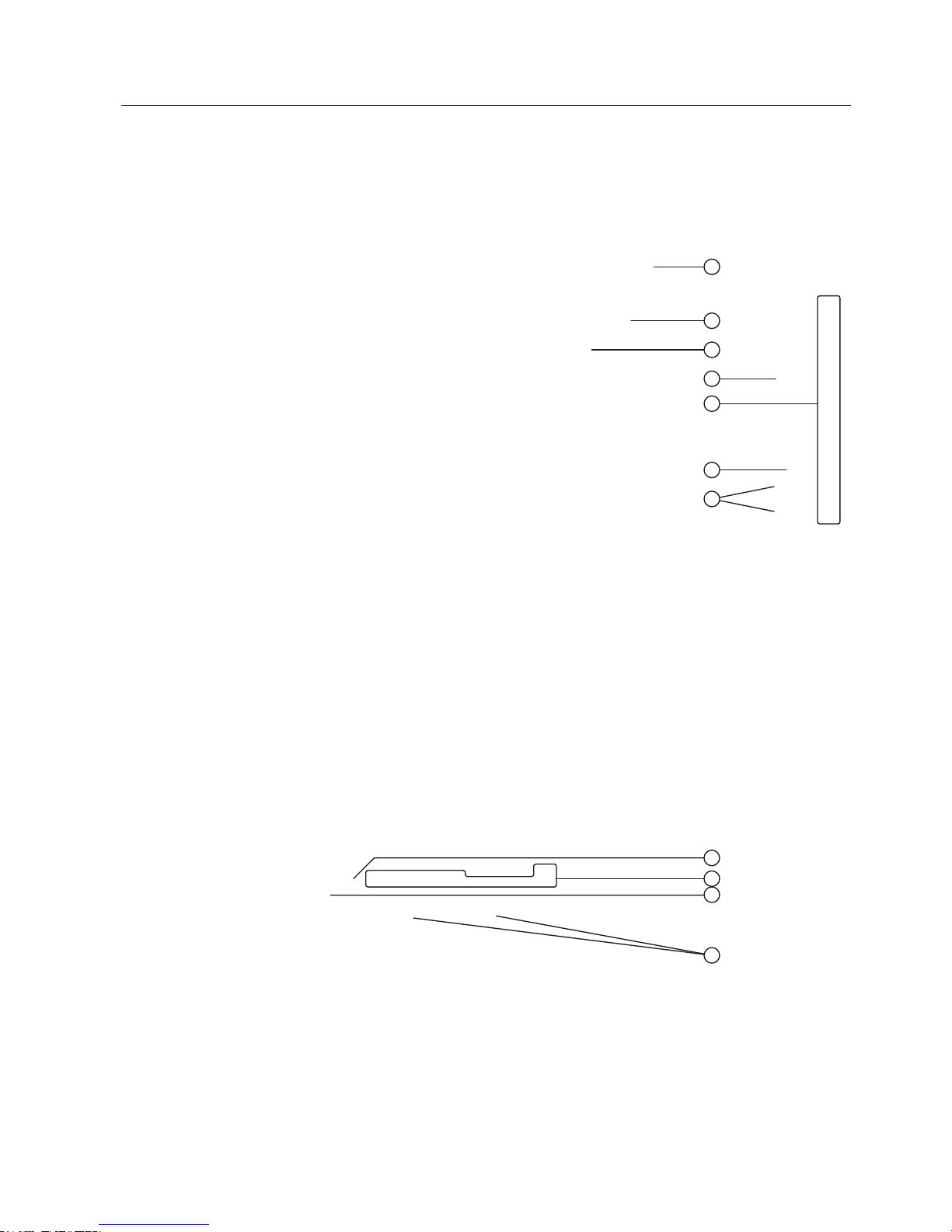
1.2 Design
Front view and side view
① Housing frame
② Front membrane
③ Display/touch screen
④ Protection for memory cards
⑤ Oblong holes for mounting clamps/air vents
⑥ Fans
⑦ Fixing element for strain relief
The term "front operating panel" as used in this manual corresponds to the front view with
operating elements.
Bottom view
① Mains terminal for power supply of HMI device
② Interfaces
③ Mains terminal for power supply of fans
④ Fans

Overview
1.2 Design
MP 377 15" Touch daylight readable (WinCC flexible)
12 Operating Instructions (Compact), 04/2009, A5E02532357-01
Rear view
① Rating plate
② Protection for memory cards
③ Mounting seal
④ DIP switch
⑤ Mains terminal for power supply of fans
⑥ Fixing elements for strain relief

Overview
1.3 Scope of delivery
MP 377 15" Touch daylight readable (WinCC flexible)
Operating Instructions (Compact), 04/2009, A5E02532357-01
13
1.3 Scope of delivery
The following components are included in the scope of delivery:
● An HMI device
● A CD with the following content:
– HMI device image for "MP 377 15" Daylight readable"
– Installation file "MP377 SetBrightness" for the add-on "SetBrightness" (.msi-Format)
– Readme file
● A pouch with the following content:
– Mounting clamps for mounting the HMI device
– One mains terminal for power supply of HMI device
– One mains terminal for power supply of fans
– One product information "Installing HMI device"
1.4 Service pack
A service pack is available for the MP 377 15" daylight readable.
The service pack includes the following components:
● A mounting seal
● A pouch with the following content:
– Mounting clamps for mounting the HMI device
– One mains terminal for power supply of HMI device
– One mains terminal for power supply of fans
– One product information "Installing HMI device"
The service pack can be ordered with the order number 6AV6675-4CA00-0AX0.

Overview
1.4 Service pack
MP 377 15" Touch daylight readable (WinCC flexible)
14 Operating Instructions (Compact), 04/2009, A5E02532357-01
MP 377 15" Touch daylight readable (WinCC flexible)
Operating Instructions (Compact), 04/2009, A5E02532357-01
15
Safety instructions and approvals
2
2.1 Validity
This manual includes important information on the operation of the MP 377 15" Touch
daylight readable in potentially explosive atmospheres of zones 2 and 22.
WARNING
Read all sections of this manual. Please observe all safety guidelines contained within the
sections. These safety instructions apply to all HMI devices that have an "Ex protection"
identifier on their type plates.
2.2 Safety notes
Working on the control cabinet
WARNING
Open Equipment
The HMI device is an open equipment. This means that the HMI device may only be
installed in a control cabinet, whereby the device can be operated from the front panel.
Access to the control cabinet in which the HMI device is installed should only be possible
by means of a key or tool and only for trained and authorized personnel.
Dangerous Voltage
Opening the control cabinet will expose high voltage parts. Contact with these parts could
be fatal.
Switch off the power supply to the cabinet before opening it.
High frequency radiation
NOTICE
Unintentional operating situations
High frequency radiation, e g. from a cellular phone, can cause unintentional operating
situations.
Safety instructions and approvals
2.3 Standards, certificates and approvals
MP 377 15" Touch daylight readable (WinCC flexible)
16 Operating Instructions (Compact), 04/2009, A5E02532357-01
Intended purpose
WARNING
Commissioning of the HMI device is forbidden until it has been absolutely ensured that the
machine in which the HMI device is to be installed complies with Directive 98/37/EC or
Directive 2006/42/EG as of 29 December 2009.
2.3 Standards, certificates and approvals
Note
The following overview shows possible approvals. The HMI device itself is certified as shown
on the label on its rear panel.
Ex approval
For the HMI device
● EN 60079-0
● EN 60079-15
● EN 61241-0
● EN 61241-1
the following approvals are in place:
II 3 G Ex nA II Tx
II 3 D Ex tD A22 IP6X T xx °C
x ... Temperature values, see design examination certificate
The design examination certificate is available at the following Internet address:
"
http://support.automation.siemens.com"
CE approval
The HMI device meets the general and safety-related requirements of the following EC
directives and conforms to the harmonized European standards (EN) for programmable logic
controllers published in the official gazettes of the European Union:
● 2004/108/EC "Electromagnetic Compatibility Directive" (EMC Directive)
● 2006/95/EC "Electrical Equipment Designed for Use within Certain Voltage Limits" (LowVoltage Directive)
● 94/9/EU "Devices and protection systems for use in potentially explosive areas"
(Guidelines for Explosion Protection)
Safety instructions and approvals
2.3 Standards, certificates and approvals
MP 377 15" Touch daylight readable (WinCC flexible)
Operating Instructions (Compact), 04/2009, A5E02532357-01
17
EC Declaration of Conformity
The EC Declarations of Conformity are available to the relevant authorities at the following
address:
Siemens AG
Industry Sector
I IA AS R&D ST
PO Box 1963
92209 Amberg
Germany
UL approval
Underwriters Laboratories Inc., to
● UL 508 (Industrial Control Equipment)
● CSA C22.2 No. 142 (Process Control Equipment)
or
Underwriters Laboratories Inc., to
● UL 508 (Industrial Control Equipment)
● CSA C22.2 No. 142 (Process Control Equipment)
● UL 1604 (Hazardous Location)
● CSA-213 (Hazardous Location)
Approved for use in
● Class I, Division 2, Group A, B, C, D Tx
● Class I, Zone 2, Group IIC Tx or
● non-hazardous locations
FM approval
Factory Mutual Research (FM) conforming to
● Approval Standard Class Number 3611, 3600, 3810
Approved for use in
● Class I, Division 2, Group A, B, C, D Tx
● Class I, Zone 2, Group IIC Tx

Safety instructions and approvals
2.3 Standards, certificates and approvals
MP 377 15" Touch daylight readable (WinCC flexible)
18 Operating Instructions (Compact), 04/2009, A5E02532357-01
Tick mark for Australia
The HMI device fulfills the requirements of standard AS/NZS 2064 (Class A).
IEC 61131
The HMI device meets the requirements and criteria conforming to IEC 61131-2,
Programmable Logic Controllers, Part 2, equipment requirements and testing.
Requesting certificates
Copies of the certificates and reports can be requested from the following address:
Siemens AG
Industry Sector
I IA AS R&D ST
PO Box 1963
92209 Amberg
Germany
Certificates are also available at the following Internet address:
"
http://support.automation.siemens.com"
Select "Product Support".
Safety instructions and approvals
2.4 Notes about Usage
MP 377 15" Touch daylight readable (WinCC flexible)
Operating Instructions (Compact), 04/2009, A5E02532357-01
19
2.4 Notes about Usage
Operation in industrial environments
The HMI device is designed for industrial use, limit class A. The following standards are met:
● Requirements for emissions EN 61000-6-4: 2007
● Requirements for interference immunity DIN EN 61000-6-2: 2005
Note
Operation in residential areas
The HMI device is not suitable for operation in residential areas: Operation of an HMI
device in residential areas can have a negative impact on radio and TV reception.
If the HMI device is used in a residential area, you must take measures to achieve Limit
Class B conforming to EN 55011 for RF interference.
Suitable measures for achieving the required RF interference level for Limit Class B include
for example:
● Installation of the HMI device in a grounded control cabinet
● Use of filters in electrical supply lines
Individual acceptance is required.
Operation in potentially explosive atmosphere, zone 2 and 22
DANGER
Degree of hazard
There is an explosion hazard when operating an HMI device that does not have explosion
protection.
Operate the HMI device in potentially explosive zones 2 and 22 only if it has been approved
and certified for such environments.
If an HMI device is operated in potentially explosive atmospheres of zone 22, pay attention
to the product information "Use in potentially explosive atmospheres of zones 2 and 22." The
product information is available at the following Internet address:
"
http://support.automation.siemens.com/WW/view/en/291285"
Safety instructions and approvals
2.4 Notes about Usage
MP 377 15" Touch daylight readable (WinCC flexible)
20 Operating Instructions (Compact), 04/2009, A5E02532357-01
WARNING
Personal injury and damage to property
Personal injury and property damage can occur in potentially explosive atmospheres if an
electric plug is disconnected from the HMI device while the system is in operation.
In potentially explosive atmospheres, always turn off power to the HMI device before
disconnecting any connectors.
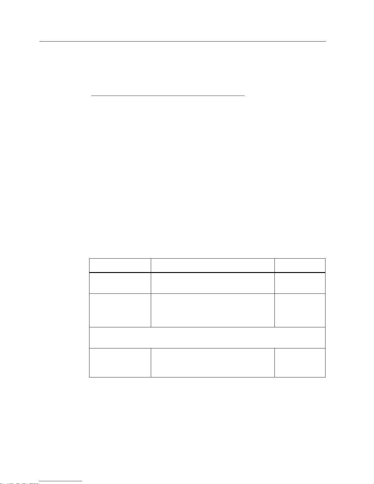
Potentially explosive atmosphere zones 2 and 22
Areas subject to explosion hazard are divided into zones. The zones are differentiated
according to the probability of the existence of an explosive atmosphere.
Zone Degree of hazard Example
2 Explosive gaseous atmosphere occurs only
seldom and for a short period
Areas around flanged pipe joints
with flat gaskets in closed rooms
22 Area in which a potentially explosive
atmosphere in the form of a cloud in the air
containing flammable dust does not usually
occur or occurs only briefly during normal
operation .
–
Safe zone No
• Outside zone 2
• Outside zone 22
• Standard applications of
distributed I/Os

Safety instructions and approvals
2.4 Notes about Usage
MP 377 15" Touch daylight readable (WinCC flexible)
Operating Instructions (Compact), 04/2009, A5E02532357-01
21
Operating conditions for Zones 2 and 22
The following operating conditions apply for Zones 2 and 22:
● The HMI device must be installed in a control cabinet. The control cabinet must meet the
following in accordance with EN 60529:
– Protection type IP54 or higher for Zone 2
– Protection type IP5x or higher for Zone 22 in case of non conductive dust
– Protection type IP6x or higher for Zone 22 in case of conductive dust
You must install the HMI device so that you provide at least protection type IP54 or IP5x
to EN 60529 on the front of the device. Consult the operating instructions of control
cabinet and HMI device for this purpose.
Make allowances for the operating and ambient conditions under which you operate the
HMI device. A manufacturer's declaration must be provided for the control cabinet in
accordance with EC Directive 94/9, stating it is fit for purpose.
● The ambient temperature range is 0 °C ≤ T ≤ 50 °C. Under these conditions, the HMI
device will satisfy temperature class Tx for category 3G and support a maximum surface
temperature of xx °C for category 3D. (x ... Temperature value, see design examination
certificate).
Refer to the operating instructions for details of limitations resulting from the ambient
temperature range.
● In situations where the temperature on the cable at the cable inlet of the control cabinet
exceeds a temperature of 70 °C, or where the temperature on the wire branching point
exceeds 80 °C under operating conditions, the temperature specifications of the cables
must match the actually measured temperatures.
● Put measures in place to ensure the rated voltage is not exceeded.
Any transient interference voltages above the rated value must not exceed 40 %.
● Protect the HMI device from mechanical loads > 7 J and the display from mechanical
loads > 4 J.
● Ensure that the atmosphere is not explosive during servicing.
Measures that impair or remove the protection type of the HMI device are not permitted
while the system is in operation.
● If the HMI device was dismantled, check the mounting seal for damage before
reassembling the HMI device. A damaged, porous or used mounting seal no longer
meets the requirements of the protection type. In this case, the mounting seal must be
replaced.
● Turn off the HMI dev
ice and the entire electrical installation in the control cabinet, if the
film on the front of the HMI device or the glass of the display on the HMI device are
damaged by a tear or hole or if the front film starts to peel off.
Exchange the HMI device. Restart the system again after the device has been
exchanged.
Safety instructions and approvals
2.5 Electro-Magnetic Compatibility
MP 377 15" Touch daylight readable (WinCC flexible)
22 Operating Instructions (Compact), 04/2009, A5E02532357-01
Approved HMI device
The HMI devices with approval for operation in potentially explosive atmospheres are listed
at the following Internet address:
"
http://support.automation.siemens.
com/WW/view/en/291285"
2.5 Electro-Magnetic Compatibility
Introduction
The HMI device fulfils, among other things, the requirements of the EMC laws pertaining to
the European domestic market.
EMC-compliant Mounting of the HMI Device
EMC-compliant mounting of the HMI device and the use of interference-proof cables will
ensure trouble-free operation. The "Directives for interference-free installation of PLCs" and
the "PROFIBUS Networks" manual also apply for the installation of the HMI device.
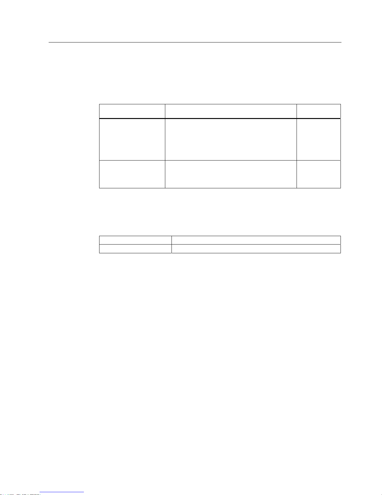
Pulse-shaped Interference
The table below shows the electromagnetic compatibility of modules in relation to pulseshaped interference. This requires the HMI device to meet the specifications and directives
for electrical installation.
Pulse-shaped
interference
Tested with Corresponds to
severity
Electrostatic discharge
in accordance with
IEC 61000-4-2
Air discharge: 8 kV
Contact discharge: 6 kV
3
Burst pulses
(high-speed transient
interference)
conforming to
IEC 61000-4-4
2 kV power supply cable
2 kV signal cable, > 30 m
1 kV signal cable, < 30 m
3
High-power surge pulses conforming to IEC 61000-4-5, external protective circuit required (refer to
the manual, Programmable Controller S7-300, Installation, chapter “Lightning and Overvoltage
Protection”).
Asymmetric coupling 2 kV power cable
DC voltage with protective elements
2 kV signal/data cable, > 30 m,
with protective elements as required
3
Safety instructions and approvals
2.5 Electro-Magnetic Compatibility
MP 377 15" Touch daylight readable (WinCC flexible)
Operating Instructions (Compact), 04/2009, A5E02532357-01
23
Sinusoidal disturbance
The table below shows the EMC properties of the modules with respect to sinusoidal
interference. This requires the HMI device to meet the specifications and directives for
electrical installation.
Sinusoidal interference Test values Corresponds to
severity
HF radiation
(electromagnetic fields)
according to IEC 610004-3
• 80% amplitude modulation at 1 kHz
with 10 V/m in the range of 80 MHz to 1 GHz
with 3 V/m in the range 1.4 GHz to 2 GHz
with 1 V/m the range 2 GHz to 2.7 GHz
• 10 V/m with 50 % pulse modulation at 900 MHz
10 V/m with 50 % pulse modulation at 1.89 GHz
3
HF interference current
on cables and cable
shielding conforming to
IEC 61000-4-6
Test voltage 10 V at 80% amplitude modulation of
1 kHz in the range from 9 kHz to 80 MHz
3
Emission of radio interference
Emission from electromagnetic fields according to EN 55011, limit value Class A, Group 1,
measured at a distance of 10 m:
30 to 230 MHz < 40 dB (μV/m) quasi-peak
230 to 1 000 MHz < 47 dB (μV/m) quasi-peak

Safety instructions and approvals
2.5 Electro-Magnetic Compatibility
MP 377 15" Touch daylight readable (WinCC flexible)
24 Operating Instructions (Compact), 04/2009, A5E02532357-01

MP 377 15" Touch daylight readable (WinCC flexible)
Operating Instructions (Compact), 04/2009, A5E02532357-01
25
Planning application
3
3.1 General information
Proper transport and storage, installation and assembly as well as careful operation and
maintenance are required to ensure trouble-free and safe operation of the HMI device.
The warranty for the HMI device will be deemed void if these stipulations are not heeded.
3.2 Mounting positions and type of fixation
Permitted mounting positions
The HMI device is designed for mounting in stationary cabinets, for example for mobile
drilling rigs and ships.
The HMI device is approved for horizontal mounting. The HMI device can be installed as
follows:
● Vertical
● Inclined at an angle between 0° and 90°
● Horizontal
Temperature Extension Kit
The "Temperature Extension Kit" lets you use the HMI device relatively independent of the
actual ambient conditions. You accomplish this feat because the "Temperature Extension
Kit" creates an environment in the cabinet that is within the limits permitted for operation of
the MP 377 15" Touch daylight readable.
If you are going to equip the HMI device with the "Temperature Extension Kit" option, you
need to select a cabinet of the appropriate size. Make allowances for the fact that the
thermal conductivity of control cabinets made of stainless steel is not as good as that of an
aluminum cabinet, for example.
You will find additional information in the "Temperature Extension Kit" operating instructions.
Planning application
3.3 Preparation for mounting
MP 377 15" Touch daylight readable (WinCC flexible)
26 Operating Instructions (Compact), 04/2009, A5E02532357-01
3.3 Preparation for mounting
Selecting the mounting location for the HMI device
Points to observe when selecting the mounting location:
● Position the HMI device so that it is not subjected to direct sunlight.
The display was designed for operation in direct sunlight.
● Position the HMI device such that it is ergonomically accessible for the user.
Choose a suitable mounting height and mounting angle.
● Make sure that you do not cover the fan and the air vents of the HMI device during
installation.
Ensuring degree of protection
The degree of protection according to the information in the chapter "Technical
Specifications (Page 54)" can only be ensured if the HMI dev
ice is installed with the supplied
mounting clamps. Additional fastening bore holes or threaded bolts are not required for the
mounting cutout.
The front material has to consist of sheet steel or material of a strength that corresponds to
at least the stability of sheet steel.
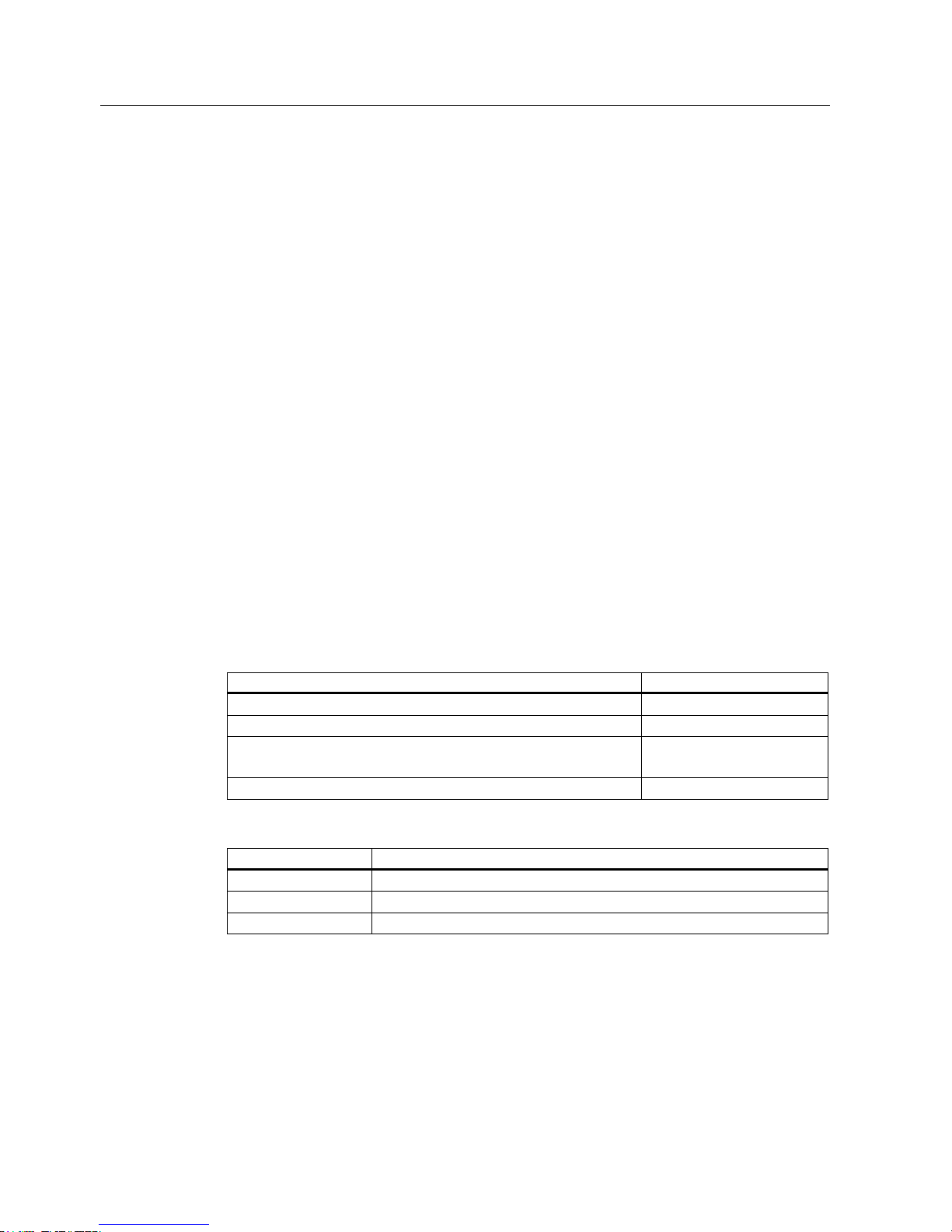
Mounting cutout
The following conditions apply to the mounting cutout:
Mounting cutout Dimensions
Material thickness with IP66 degree of protection 1.5 to 5 mm
Material thickness with enclosure type 4X/type 12 (indoor use only) 3 to 5 mm
Permitted deviation from plane
This condition must be fulfilled for the mounted HMI device.
≤ 0.5 mm
Permitted surface roughness in the area of the mounting seal ≤ 120 µm (Rz 120)
The following table shows the dimensions of the mounting cutout:
Dimensions HMI device
Width 367+1 mm
Height 289+1 mm
Depth 105.5 mm
Planning application
3.3 Preparation for mounting
MP 377 15" Touch daylight readable (WinCC flexible)
Operating Instructions (Compact), 04/2009, A5E02532357-01
27
Maintaining clearances
The HMI device must be installed with the following clearances:
Where Clearance
Observe a clearance above and below the mounting cutout for
ventilation of
50 mm
Right and left of the mounting cut-out for the mounting clamps 18 mm
At the rear in addition to the mounting depth of the HMI device at
least
≥ 10 mm
Note
Ensure that the maximum ambient temperature is not exceeded when mounting the device
in a control cabinet.
You can install the option "TEK – Temperature Extension Kit", if necessary.
 Loading...