

Siemens SIMATIC TP 270, SIMATIC OP 270, SIMATIC MP 270B Operating Instructions Manual

Preface
Overview
1
SIMATIC HMI
HMI device
TP 270, OP 270, MP 270B
(WinCC flexible)
Operating Instructions
Safety notes and general
information
Plan deployment
Installation and connection
Operating elements and
indicators
Operating system and
configuration
Prepare and backup project
Runtime functionalities of a
project
2
3
4
5
6
7
8
Order number 6AV6691-1DD01-0AB0
Operate project
Operating recipes
Maintenance/Service
Technical data
Appendix
Abbreviations
Glossary
9
10
11
12
A
B
C
Edition 03/2004
A5E00280664-01
이 기기는 업무용(A급) 전자파 적합기기로서 판매자 또는 사용자는 이 점을 주의하시기 바라며 가정 외의 지역에서 사용하는 것을 목적으로 합니다.
Safety Guidelines
This manual contains notices which you should observe to ensure your own personal safety as well as to avoid
property damage. The notices referring to your personal safety are highlighted in the manual by a safety alert
symbol, notices referring to property damage only have no safety alert symbol.
Danger
indicates an imminently hazardous situation which, if not avoided, will result in death or serious injury.
Warning
indicates a potentially hazardous situation which, if not avoided, could result in death or serious injury.
Caution
used with the safety alert symbol indicates a potentially hazardous situation which, if not avoided, may
result in minor or moderate injury.
Caution
used without safety alert symbol indicates a potentially hazardous situation which, if not avoided, may
result in property damage.
Notice
used without the safety alert symbol indicates a potential situation which, if not avoided, may result in
an undesirable result or state.
When several danger levels apply, the notices of the highest level (lower number) are always displayed. If a
notice refers to personal damages with the safety alert symbol, then another notice may be added warning of
property damage.
Qualified Personnel
The device/system may only be set up and operated in conjunction with this documentation. Only qualified
personnel should be allowed to install and work on the equipment. Qualified persons are defined as persons who
are authorized to commission, to earth, and to tag circuits, equipment and systems in accordance with
established safety practices and standards.
Intended Use
Please note the following:
Warning
This device and its components may only be used for the applications described in the catalog or
technical description, and only in connection with devices or components from other manufacturers
approved or recommended by Siemens.
This product can only function correctly and safely if it is transported, stored, set up and installed
correctly, and operated and maintained as recommended.
Trademarks
All designations marked with ® are registered trademarks of Siemens AG. Other designations in this
documentation might be trademarks which, if used by third parties for their purposes, might infringe upon the
rights of the proprietors.
Copyright Siemens AG, 2004. All rights reserved
Reproduction, transmission or use of this document or its contents is not permitted without
express written authority. Offenders will be liable for damages. All rights, including rights
created by patent grant or registration of a utility model or design, are reserved.
Siemens AG
Automation and Drives Group
P.O. Box 4848, D-90327 Nuremberg (Germany)
Siemens Aktiengesellschaft 6AV6691-1DD01-0AB0
Disclaimer of Liability
We have checked the contents of this manual for agreement with the hardware and
software described. Since deviations cannot be precluded entirely, we cannot guarantee
full agreement. However, the data in the manual are reviewed regularly, and any
necessary corrections will be included in subsequent editions. Suggestions for
improvement are welcomed.
© Siemens AG 2004
Technical data subject to change

Preface
Purpose of the manual
This manual provides the required information and documentation for machine construction
in compliance with DIN 8418. The information contained relates to the device, its installation
site, transport, storage, use and maintenance.
The manual is aimed at the following target groups:
• Users
• Commissioners
• Service technicians
• Maintenance engineers
Read carefully the Chapter "Safety and General Information".
The help integrated in WinCC flexible, namely the WinCC flexible Information System,
contains further information. The Information System provides instructions, examples and
references in electronic form.
Basic knowledge required
A general knowledge of automation technology and process communication is necessary in
order to understand the manual.
It is assumed users have good basic knowledge in the use of personal computers and MS
Windows operating systems.
Manual application
The manual applies to the SIMATIC MP 270B, OP 270 and TP 270 in connection with the
WinCC flexible 2004 software packet.
Modifications compared to previous release 12/2001
The manual describes the use of the HMI devices together with WinCC flexible 2004. For
implementation with WinCC flexible 2004, the MP 270B 6" device model is also available.
The previous version, 12/2001, can still be used on the HMI device with ProTool.
Position in the information scheme
This manual is part of the SIMATIC HMI documentation. The information below presents an
overview of the information scheme of SIMATIC HMI.
TP 270, OP 270, MP 270B (WinCC flexible)
Operating Instructions, Edition 03/2004, 6AV6691-1DD01-0AB0
i

Preface
User manual
• WinCC flexible Micro:
– Describes basic configuration principles using the WinCC flexible Micro Engineering
System
• WinCC flexible Compact/Standard/Advanced:
– Describes basic configuration principles using the WinCC flexible Compact
Engineering System/WinCC flexible Standard/WinCC flexible Advanced
• WinCC flexible Runtime:
– Describes commissioning and operating the runtime project on a PC.
• WinCC flexible Migration:
– Describes how to convert an existing ProTool project to WinCC flexible.
– Describes how to convert an existing WinCC project to WinCC flexible.
– Describes the conversion of ProTool projects together with changing the HMI device
from OP7 to OP 77B.
– Describes the conversion of ProTool projects together with changing the graphic HMI
devices to Windows CE devices.
• Communication
– Communication Part 1 describes the connection of the HMI device to SIMATIC PLCs.
– Communication Part 2 describes the connection of the HMI device to third-party PLCs.
Operating instructions
• Operating instructions for HMI devices SIMATIC OP 77B,
TP 170micro/TP 170A/TP 170B/OP 170B, SIMATIC Mobile Panel 170, SIMATIC
TP 270/OP 270/MP 270B, SIMATIC MP 370.
• Quick reference manuals for the SIMATIC OP 77B and SIMATIC Mobile Panel 170 HMI
devices.
Getting started
• WinCC flexible for beginners:
– Provides step-by-step instructions on the principles of configuring screens, alarms,
recipes and screen navigation using an project example.
• WinCC flexible for advanced users:
– Provides step-by-step instructions on the principles of configuring logs, project reports,
scripts, user administration, multilingual projects and integration in STEP 7 using an
project example.
• WinCC flexible Options:
– Provides step-by-step instructions on the principles of configuring the options
WinCC flexible Sm@rtServices, Sm@rtAccess and OPC-Server using an project
example.
TP 270, OP 270, MP 270B (WinCC flexible)
ii Operating Instructions, Edition 03/2004, 6AV6691-1DD01-0AB0

Preface
Online availability
The following links provide direct access to technical documentation on SIMATIC products
and systems in English, German, French, Italian and Spanish:
• SIMATIC Guide Technical Documentation in German:
http://www.ad.siemens.de/simatic/portal/html_00/techdoku.htm
• SIMATIC Guide for Technical Documentation in English:
http://www.ad.siemens.de/simatic/portal/html_76/techdoku.htm
Conventions
A distinction has been made in the naming of the configuration and runtime software:
• "WinCC flexible" refers to the configuration software.
• "Runtime" refers to the runtime software capable of running on the HMI devices.
Generally, the term "WinCC flexible" is used. The version identification, e.g.
"WinCC flexible 2004", is always used when it is necessary to make a version distinction.
The following text highlights are intended to simplify reading the manual:
Display method Application
"Add screens"
"File > Edit" Operation sequences, e.g. menu commands, pop-up menu commands.
<F1>, <Alt+P> Keyboard input
• Terms which appear on the user interface, e.g. dialog names, tabs,
buttons, menu commands.
• Required input, e.g. limit vales, tag values.
• Path information
Trademarks
Also observe the information identified as follows:
Note
Notes contain important information about the product or operation of the product. Notes
also refer to areas within the documentation which require special attention.
All names identified by ® are registered trademarks of the Siemens AG.
HMI®
SIMATIC®
SIMATIC HMI®
SIMATIC ProTool®
SIMATIC WinCC®
SIMATIC WinCC flexible®
SIMATIC MP 270B®
SIMATIC OP 270®
SIMATIC TP 270®
The remaining trademarks in this publication may be trademarks whose use by third parties
for their own purposes could violate the rights of the owner.
TP 270, OP 270, MP 270B (WinCC flexible)
Operating Instructions, Edition 03/2004, 6AV6691-1DD01-0AB0
iii

Preface
Representatives and agents
If you have any further queries regarding products described in the manual, please contact
the Siemens representatives or agents responsible for your area.
Contact partners can be located under:
http://www.siemens.com/automation/partner
Training center
We offer relevant courses to simplify your introduction to the world of automation systems.
Please contact your regional training center or our central training center in D 90327
Nuernberg, Germany for details.
Phone: +49 (911) 895-3200.
Internet: http://www.sitrain.com
Service & Support on the Internet
Service & Support provides comprehensive, additional information on SIMATIC products
through online services at "http://www.siemens.com/automation/service&support":
• The Newsletter, containing the latest information on your products.
• Numerous documents are available by searching through Service & Support.
• A forum, in which users and specialists can exchange experiences.
• The latest product information, FAQs and downloads.
• Contact partners for Automation & Drives are listed in the contact partner database.
• Information on on-site services, repairs, spare parts and much more under the term
"Services".
TP 270, OP 270, MP 270B (WinCC flexible)
iv Operating Instructions, Edition 03/2004, 6AV6691-1DD01-0AB0

Preface
A&D Technical Support
Available round the clock, worldwide:
Worldwide (Nuremberg)
Technical Support
(Free Contact)
Local time: Mon.-Fri. 7:00 to 17:00.
Phone: +49 (0) 180 5050-222
Fax: +49 (0) 180 5050-223
E-mail: adsupport@siemens.com
GMT: +1:00
Europe/Africa (Nuremberg)
Authorization
Local time: Mon.-Fri. 7:00 to 17:00.
Phone: +49 (911) 895-7200
Fax: +49 (911) 895-7201
E-mail:
adauthorisierung@siemens.com
GMT: +1:00
Johnson City
Worldwide (Nuremberg)
Technical Support
(fee-based, only with SIMATIC Card)
Local time: 0:00 to 24:00, 365 days a year
Phone: +49 (911) 895-7777
Fax: +49 (911) 895-7001
GMT: +1:00
United States (Johnson City)
Technical Support and Authorization
Local time: Mon.-Fri. 8:00 to 19:00.
Phone: +1 423 461-2522
Fax: +1 423 461-2289
E-mail:
simatic.hotline@sea.siemens.com
GMT: -5:00
Nuremberg
SIMATIC Hotline
Beijing
Asia/Australia (Beijing)
Technical Support and Authorization
Local time: Mon.-Fri. 08:30 to 5:30 pm.
Phone: +86 10 64 75 75 75
Fax: +86 10 64 74 74 74
E-mail:
adsupport.asia@siemens.com
GMT: +8:00
Information is available in English and German.
TP 270, OP 270, MP 270B (WinCC flexible)
Operating Instructions, Edition 03/2004, 6AV6691-1DD01-0AB0
v

Preface
TP 270, OP 270, MP 270B (WinCC flexible)
vi Operating Instructions, Edition 03/2004, 6AV6691-1DD01-0AB0

Table of contents
Preface ........................................................................................................................................................i
1 Overview................................................................................................................................................. 1-1
1.1 Introduction ................................................................................................................................ 1-1
1.2 Field of Application..................................................................................................................... 1-2
1.3 Configuring with WinCC flexible................................................................................................. 1-3
1.4 Features..................................................................................................................................... 1-4
1.5 Functional scope........................................................................................................................ 1-7
1.6 Communication with PLCs....................................................................................................... 1-11
1.7 Options..................................................................................................................................... 1-12
1.7.1 Hardware options..................................................................................................................... 1-12
1.7.1.1 Backup battery ......................................................................................................................... 1-12
1.7.1.2 PC card / CF card .................................................................................................................... 1-14
1.7.2 Software options ...................................................................................................................... 1-16
1.7.2.1 Internet Explorer ...................................................................................................................... 1-16
2 Safety notes and general information ..................................................................................................... 2-1
2.1 Safety notes ............................................................................................................................... 2-1
2.2 General information ................................................................................................................... 2-1
3 Plan deployment..................................................................................................................................... 3-1
3.1 Transport.................................................................................................................................... 3-1
3.2 Installation notes ........................................................................................................................ 3-2
3.3 Installation locations and type of protection...............................................................................3-3
3.4 Producing the installation cut-out............................................................................................... 3-4
4 Installation and connection ..................................................................................................................... 4-1
4.1 Check shipment ......................................................................................................................... 4-1
4.2 Installation of the HMI device..................................................................................................... 4-1
4.2.1 Installing the MP 270B Keys or OP 270 .................................................................................... 4-1
4.2.2 Installing the MP 270B Touch or TP 270 10"............................................................................. 4-3
4.3 Connecting the HMI device........................................................................................................ 4-5
4.3.1 Conditions .................................................................................................................................. 4-5
4.3.2 Interfaces ................................................................................................................................... 4-6
4.3.3 Connecting the potential equalization........................................................................................ 4-8
4.3.4 Connecting peripheral equipment..........................................................................................
4.3.4.1 Connect print
4.3.4.2 Connect external keyboard and mouse ................................................................................... 4-12
4.3.5 Connecting the PLC................................................................................................................. 4-13
4.3.6 Connecting the configuration computer ................................................................................... 4-15
4.3.7 Connecting an uninterruptible power supply (UPS)................................................................. 4-16
er.........................................................................................................................
.. 4-10
4-10
TP 270, OP 270, MP 270B (WinCC flexible)
Operating Instructions, Edition 03/2004, 6AV6691-1DD01-0AB0
vii

Table of contents
4.3.8 Connecting the power supply................................................................................................... 4-17
4.4 Switch on and test the HMI device........................................................................................... 4-18
5 Operating elements and indicators ......................................................................................................... 5-1
5.1 MP 270B Touch and TP 270...................................................................................................... 5-1
5.2 MP 270B Keys and OP 270 ....................................................................................................... 5-2
5.2.1 Key pads .................................................................................................................................... 5-2
5.2.2 Function keys ............................................................................................................................. 5-5
5.2.3 System keys............................................................................................................................... 5-6
5.2.4 Labeling the softkeys ................................................................................................................. 5-8
5.3 Operation with external keyboard/mouse ................................................................................ 5-12
6 Operating system and configuration ....................................................................................................... 6-1
6.1 HMI device loader ...................................................................................................................... 6-1
6.2 Windows CE Control Panel........................................................................................................ 6-2
6.2.1 Open Control Panel.................................................................................................................... 6-2
6.2.2 Communication .......................................................................................................................... 6-5
6.2.3 Date/time.................................................................................................................................... 6-5
6.2.4 InputPanel .................................................................................................................................. 6-6
6.2.5 Network ...................................................................................................................................... 6-6
6.2.6 OP .............................................................................................................................................. 6-7
6.2.7 Printer....................................................................................................................................... 6-11
6.2.8 Regional Settings..................................................................................................................... 6-13
6.2.9 Screensaver ............................................................................................................................. 6-14
6.2.10 System ..................................................................................................................................... 6-15
6.2.11 UPS.......................................................................................................................................... 6-16
6.2.12 Volume & Sounds .................................................................................................................... 6-17
6.3 Network operation .................................................................................................................... 6-18
6.3.1 Basic principles ........................................................................................................................ 6-18
6.3.2 Configuring the HMI device for network operation................................................................... 6-19
6.3.3 Test network............................................................................................................................. 6-21
6.3.4 Configuring network access..................................................................................................... 6-22
7 Prepare and backup project.................................................................................................................... 7-1
7.1 Transfer project to the HMI device............................................................................................. 7-1
7.1.1 Commissioning for the first time.........................................................................................
7.1.2 Rec
ommiss
ioning....................................................................................................................... 7-3
........ 7-1
7.2 Transfer...................................................................................................................................... 7-3
7.2.1 Start transfer manually............................................................................................................... 7-3
7.2.2 Start transfer automatically ........................................................................................................ 7-4
7.2.3 Transfer mode options ............................................................................................................... 7-5
7.2.4 Test project ................................................................................................................................ 7-8
7.2.5 Uploading project ..................................................................................................................... 7-10
7.3 System settings........................................................................................................................ 7-12
7.3.1 Set language ............................................................................................................................ 7-12
7.3.2 Set operating mode.................................................................................................................. 7-13
7.4 Other transfer functions............................................................................................................ 7-14
7.4.1 Functions.................................................................................................................................. 7-14
7.4.2 Backup and Restore................................................................................................................. 7-15
7.4.3 Update operating system ......................................................................................................... 7-18
7.4.4 Transferring authorizations ...................................................................................................... 7-21
7.4.5 Transferring options ................................................................................................................. 7-22
TP 270, OP 270, MP 270B (WinCC flexible)
viii Operating Instructions, Edition 03/2004, 6AV6691-1DD01-0AB0

Table of contents
8 Runtime functionalities of a project ......................................................................................................... 8-1
8.1 Screen objects ........................................................................................................................... 8-1
8.2 Alarms ........................................................................................................................................ 8-2
8.3 Tags ........................................................................................................................................... 8-3
8.4 Logs ........................................................................................................................................... 8-3
8.5 Reports....................................................................................................................................... 8-5
8.6 System functions and scripts ..................................................................................................... 8-6
8.7 Safety ......................................................................................................................................... 8-7
8.8 Other operating functions........................................................................................................... 8-9
9 Operate project....................................................................................................................................... 9-1
9.1 Basic principles of operation ...................................................................................................... 9-1
9.1.1 Basics for operation in runtime .................................................................................................. 9-1
9.1.2 Operating the touch panel.......................................................................................................... 9-3
9.1.2.1 Operating touch objects ............................................................................................................. 9-3
9.1.2.2 Input of values............................................................................................................................ 9-5
9.1.2.3 Input of numeric values.............................................................................................................. 9-5
9.1.2.4 Input of alphanumeric values..................................................................................................... 9-8
9.1.2.5 Calling the operator note.......................................................................................................... 9-10
9.1.3 Operating a keyboard device ................................................................................................... 9-11
9.1.3.1 Functions of the system keys................................................................................................... 9-11
9.1.3.2 Functions of the key combinations........................................................................................... 9-12
9.1.3.3 Input of values.......................................................................................................................... 9-15
9.1.3.4 Calling the operator note.......................................................................................................... 9-15
9.2 Controlling graphic objects....................................................................................................... 9-16
9.2.1 Button....................................................................................................................................... 9-16
9.2.1.1 Description ............................................................................................................................... 9-16
9.2.1.2 Touch control ........................................................................................................................... 9-17
9.2.1.3 Keyboard control...................................................................................................................... 9-17
9.2.1.4 Mouse and keyboard control.................................................................................................... 9-18
9.2.2 Switch....................................................................................................................................... 9-18
9.2.2.1 Description ............................................................................................................................... 9-18
9.2.2.2 Touch control ........................................................................................................................... 9-19
9.2.2.3 Keyboard control...................................................................................................................... 9-19
9.2.2.4 Mouse and keyboard control.............................................................................................
9.2.3 I/O field
9.2.3.1 Des
..................................................................................................................................... 9-20
cription ............................................................................................................................... 9-20
....... 9-19
9.2.3.2 Touch control ........................................................................................................................... 9-20
9.2.3.3 Keyboard control...................................................................................................................... 9-21
9.2.3.4 Mouse and keyboard control.................................................................................................... 9-21
9.2.4 Graphic I/O field ....................................................................................................................... 9-22
9.2.4.1 Description ............................................................................................................................... 9-22
9.2.4.2 Touch control ........................................................................................................................... 9-22
9.2.4.3 Keyboard control...................................................................................................................... 9-23
9.2.4.4 Mouse and keyboard control.................................................................................................... 9-23
9.2.5 Symbolic I/O field ..................................................................................................................... 9-24
9.2.5.1 Description ............................................................................................................................... 9-24
9.2.5.2 Touch control ........................................................................................................................... 9-24
9.2.5.3 Keyboard control...................................................................................................................... 9-25
9.2.5.4 Mouse and keyboard control.................................................................................................... 9-25
9.2.6 Alarm indicator ......................................................................................................................... 9-26
9.2.6.1 Description ............................................................................................................................... 9-26
TP 270, OP 270, MP 270B (WinCC flexible)
Operating Instructions, Edition 03/2004, 6AV6691-1DD01-0AB0
ix

Table of contents
9.2.6.2 Touch control ........................................................................................................................... 9-26
9.2.6.3 Mouse control........................................................................................................................... 9-27
9.2.7 Alarm view................................................................................................................................ 9-27
9.2.7.1 Description ............................................................................................................................... 9-27
9.2.7.2 Touch control ........................................................................................................................... 9-28
9.2.7.3 Keyboard control ...................................................................................................................... 9-29
9.2.7.4 Mouse and keyboard control.................................................................................................... 9-29
9.2.8 Simple alarm view .................................................................................................................... 9-30
9.2.8.1 Description ............................................................................................................................... 9-30
9.2.8.2 Touch control ........................................................................................................................... 9-31
9.2.8.3 Keyboard control ...................................................................................................................... 9-31
9.2.8.4 Mouse and keyboard control.................................................................................................... 9-31
9.2.9 Recipe view.............................................................................................................................. 9-32
9.2.9.1 Description ............................................................................................................................... 9-32
9.2.9.2 Touch control ........................................................................................................................... 9-33
9.2.9.3 Keyboard control ...................................................................................................................... 9-33
9.2.9.4 Mouse and keyboard control.................................................................................................... 9-34
9.2.10 Simple recipe view ................................................................................................................... 9-35
9.2.10.1 Description ............................................................................................................................... 9-35
9.2.10.2 Touch control ........................................................................................................................... 9-36
9.2.10.3 Keyboard control ...................................................................................................................... 9-36
9.2.10.4 Mouse and keyboard control.................................................................................................... 9-37
9.2.11 Bar............................................................................................................................................ 9-38
9.2.12 Trend view................................................................................................................................ 9-39
9.2.12.1 Description ............................................................................................................................... 9-39
9.2.12.2 Touch control ........................................................................................................................... 9-40
9.2.12.3 Keyboard control ...................................................................................................................... 9-41
9.2.12.4 Mouse and keyboard control.................................................................................................... 9-41
9.2.13 Slider control ............................................................................................................................ 9-42
9.2.13.1 Description ............................................................................................................................... 9-42
9.2.13.2 Touch control ........................................................................................................................... 9-43
9.2.13.3 Keyboard control ...................................................................................................................... 9-43
9.2.13.4 Mouse and keyboard control............................................................................................
9.2.14 Gauge.......................................................................................................................................
9.2.15 Date/time field ..........................................................................................................................
........ 9-44
9-44
9-45
9.2.15.1 Description ............................................................................................................................... 9-45
9.2.15.2 Touch control ........................................................................................................................... 9-45
9.2.15.3 Keyboard control ...................................................................................................................... 9-46
9.2.15.4 Mouse and keyboard control.................................................................................................... 9-46
9.2.16 Clock ........................................................................................................................................ 9-47
9.2.17 User view ................................................................................................................................. 9-48
9.2.17.1 Description ............................................................................................................................... 9-48
9.2.17.2 Touch control ........................................................................................................................... 9-49
9.2.17.3 Keyboard control ...................................................................................................................... 9-49
9.2.17.4 Mouse and keyboard control.................................................................................................... 9-49
9.2.18 Simple user view ...................................................................................................................... 9-50
9.2.18.1 Description ............................................................................................................................... 9-50
9.2.18.2 Touch control ........................................................................................................................... 9-50
9.2.18.3 Keyboard control ...................................................................................................................... 9-50
9.2.18.4 Mouse and keyboard control.................................................................................................... 9-51
9.2.19 Status/Force............................................................................................................................. 9-52
9.2.19.1 Description ............................................................................................................................... 9-52
9.2.19.2 Touch control ........................................................................................................................... 9-53
9.2.19.3 Keyboard control ...................................................................................................................... 9-53
9.2.19.4 Mouse and keyboard control.................................................................................................... 9-54
9.2.20 Sm@rtClient view..................................................................................................................... 9-55
9.2.20.1 Description ............................................................................................................................... 9-55
TP 270, OP 270, MP 270B (WinCC flexible)
x Operating Instructions, Edition 03/2004, 6AV6691-1DD01-0AB0

Table of contents
9.2.20.2 Touch control ........................................................................................................................... 9-57
9.2.20.3 Keyboard control...................................................................................................................... 9-57
9.2.20.4 Mouse and keyboard control.................................................................................................... 9-58
9.2.21 Symbol library .......................................................................................................................... 9-58
9.2.21.1 Description ............................................................................................................................... 9-58
9.2.21.2 Touch control ........................................................................................................................... 9-59
9.2.21.3 Mouse control........................................................................................................................... 9-59
10 Operating recipes ................................................................................................................................. 10-1
10.1 Recipes .................................................................................................................................... 10-1
10.2 Structure of recipes.................................................................................................................. 10-3
10.3 Structure of recipe data records............................................................................................... 10-4
10.4 Recipe application.................................................................................................................... 10-5
10.4.1 Transfer of recipe data records................................................................................................ 10-5
10.4.2 Configuration of recipes ........................................................................................................... 10-6
10.4.3 Scenario: Entering recipe data records in Runtime ................................................................. 10-8
10.4.4 Scenario: Manual production sequence ................................................................................ 10-10
10.4.5 Scenario: Automatic production sequence ............................................................................ 10-12
10.5 Displaying recipes.................................................................................................................. 10-13
10.5.1 Viewing and editing recipes in Runtime................................................................................. 10-13
10.5.2 Behavior of the recipe view in Runtime ................................................................................. 10-15
10.6 Recipe data record administration ......................................................................................... 10-15
10.6.1 Recipe data record administration ......................................................................................... 10-15
10.6.2 Synchronizing a recipe data record ....................................................................................... 10-17
10.6.3 Read recipe data record from PLC ........................................................................................ 10-18
10.6.4 Transfer recipe record to PLC................................................................................................ 10-18
10.6.5 Exporting and importing recipe data records ......................................................................... 10-19
10.6.6 Reactions to modifications of the recipe structure ................................................................. 10-20
10.7 Example ................................................................................................................................. 10-21
10.7.1 Example: Creating a recipe.................................................................................................... 10-21
10.7.2 Example: Configuring a recipe screen................................................................................... 10-23
11 Maintenance/Service ............................................................................................................................ 11-1
11.1 Clean screen/keyboard foil ................................................................................................
11.1.1 General information
11.1.2
Notes on the touch panel ......................................................................................................... 11-2
................................................................................................................. 11-1
...... 11-1
11.2 Replacing the optional backup battery..................................................................................... 11-3
12 Technical data ...................................................................................................................................... 12-1
12.1 Dimension drawings................................................................................................................. 12-1
12.1.1 MP 270B 10" Touch, TP 270 10" dimensions.......................................................................... 12-1
12.1.2 MP 270B 6" Touch, TP 270 6" dimensions.............................................................................. 12-2
12.1.3 Dimensions, MP 270B 10" Keys, OP 270 10" ......................................................................... 12-3
12.1.4 Dimensions, OP 270 6"............................................................................................................ 12-4
12.2 Technical data.......................................................................................................................... 12-5
12.3 EMC requirements ................................................................................................................... 12-8
12.4 Interfaces ................................................................................................................................. 12-9
TP 270, OP 270, MP 270B (WinCC flexible)
Operating Instructions, Edition 03/2004, 6AV6691-1DD01-0AB0
xi

Table of contents
A Appendix.................................................................................................................................................A-1
A.1 Certificates and Directives .........................................................................................................A-1
A.1.1 Approvals ...................................................................................................................................A-1
A.1.2 ESD guidelines...........................................................................................................................A-2
A.2 System alarms ...........................................................................................................................A-3
B Abbreviations..........................................................................................................................................B-1
B.1 Abbreviations .............................................................................................................................B-1
C Glossary .................................................................................................................................................C-1
Index
Tables
Table 1-1
Table 1-2 Communication with PLCs from other manufacturers ............................................................. 1-11
Table 12-1 9-pin Sub-D plug (pin).............................................................................................................. 12-9
Table 12-2 9-pin Sub-D socket (configuration via switch).......................................................................... 12-9
Table 12-3 9-pin Sub-D plug (pin)............................................................................................................ 12-10
Table 12-4 RJ45 plug connection............................................................................................................. 12-10
Table 12-5 USB standard plug................................................................................................................. 12-11
Communication with SIMATIC PLCs ....................................................................................... 1-11
TP 270, OP 270, MP 270B (WinCC flexible)
xii Operating Instructions, Edition 03/2004, 6AV6691-1DD01-0AB0

Overview
1.1 Introduction
HMI devices in the middle performance range
The Multi Panel MP 270B, Touch Panel TP 270 and Operator Panel OP 270 extend the
product spectrum in the middle performance range.
The HMI devices are based on the innovative standard operating system, Microsoft Windows
CE. The robustness and speed of the dedicated hardware solutions are combined with the
flexibility of the PC world.
The MP 270B represents the "Multifunctional Platform" product category and is distinguished
by its variable deployment. This product category is positioned in the product hierarchy
between the process-related, optimized application components, such as operator panels
and controllers, and industrial PCs.
The panels TP 270 and OP 270 are downgraded models and less expensive, but still provide
convincing functionality
The comprehensive product range allows users to choose the HMI device most suited to
their needs. All HMI devices include the following advantages:
1
• High degree of configuration efficiency
• Configuration simulation on the configuration computer - no PLC required
• Clear display and easy process operation using a Window-Based user interface
• Large selection of predefined screen objects for use during configuration
• Dynamic screen objects, e.g. moving objects
• Uncomplicated and quick handling of recipes and data records in recipe screens and
recipe views
• Logging of alarms, process values and login/logout procedures
• Creation of vector graphics using the WinCC flexible configuration software without an
external graphics editor,
• Transfer:
– Automatic switchover to transfer mode
– Transfer via MPI, PROFIBUS DP, USB and Ethernet
– Serial transfer
– Transfer via TeleService
• Standard connections to SIMATIC S5/DP, SIMATIC S7 and SIMATIC 505, as well as to
PLCs from other manufacturers
TP 270, OP 270, MP 270B (WinCC flexible)
Operating Instructions, Edition 03/2004, 6AV6691-1DD01-0AB0
1-1

Overview
1.2 Field of Application
Position in the SIMATIC HMI environment
The HMI devices were designed for the middle performance range. They meet the demands
placed on performance, display possibilities and price/performance ratio. In addition, they
extend the communication potential of the office world. Customer needs and requests were
taken into account in respect to extending data transfer functions, simplifying operation, and
increasing acceptance when compared with Windows CE units.
The HMI devices not only support the classic HMI applications (visualization with WinCC
flexible) but also additional applications, such as process diagnostics (ProAgent).
1.2 Field of Application
Overview
The HMI device allows graphic display of operating statuses, current process data and errors
of connected PLCs. The user can operate and observe the machine or system being
monitored easily using the HMI device.
Applicable areas of use include machine and apparatus construction sectors, printing and
packing industries, automobile and electrical industries and chemical and pharmaceutical
industries.
The high degree of protection (IP65 on the front side) and avoidance of moving storage
media, such as hard disks and floppy disks, ensure that the HMI device is suitable for use in
rough industrial environments and on site where a machine is located.
Possible installation locations for the HMI device:
• Switching cabinets/consoles
• 19" cabinets/racks (keyboard units)
Connection options for external peripherals (keyboard, mouse and printer) via a USB port,
for example, and the possible use of CF and PC cards support multifunctionality. Due to the
fact that the HMI device is equipped with high performance basic hardware and has a
minimum installation depth means that it fulfills all the requirements for operation in the
vicinity of the machine.
The HMI device can be used to:
• Operate and monitor the process using the menu system. Setpoint values or control
element settings can be modified by entering values or activating configured softkeys
• Display processes, machines and systems on full-graphic, dynamic screens
• Display and process alarms and tags through output fields, bar graphs or trend curves
• Use input to intervene directly in the running process
TP 270, OP 270, MP 270B (WinCC flexible)
1-2 Operating Instructions, Edition 03/2004, 6AV6691-1DD01-0AB0
Overview
1.3 Configuring with WinCC flexible
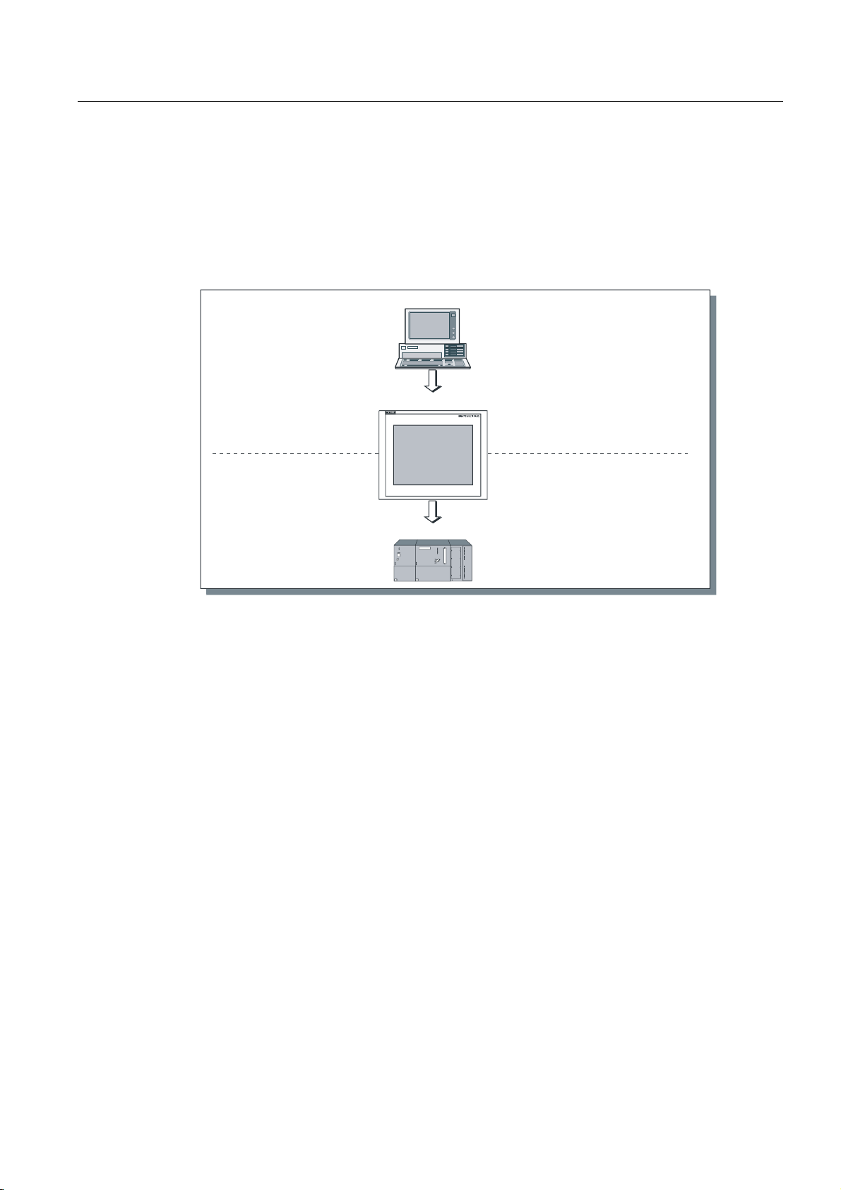
1.3 Configuring with WinCC flexible
Introduction
In order to operate a machine or system using an HMI device, the user interface must be
configured for the HMI device. This procedure is referred to as the "configuration phase".
PC/PU
Create project data
Configuration phase
Save project data
Test the configuration
Simulate configuration
Principle
Operating unit
PLC
Process running phase
Figure 1-1 Configuration and process running phases
Download project data
Connected to PLC
1. Configuring the functionality of the user interface. This includes the following:
– Graphics
– Text
– Customized functions
– Operating and indicator objects
Use a configuration computer (PC or PU) with the WinCC flexible configuration software.
2. Connect the configuration computer to the HMI device.
The following connection options are available:
– Serial
– MPI/PROFIBUS DP
– USB or Ethernet interface
– Standard modem path
3. Transfer the configuration to the HMI device.
4. Connect the HMI device to the PLC.
TP 270, OP 270, MP 270B (WinCC flexible)
Operating Instructions, Edition 03/2004, 6AV6691-1DD01-0AB0
1-3
Overview
1.4 Features
Result
The HMI device communicates with the PLC and responds to the program progress in the
PLC ("process running phase") according to the information configured.
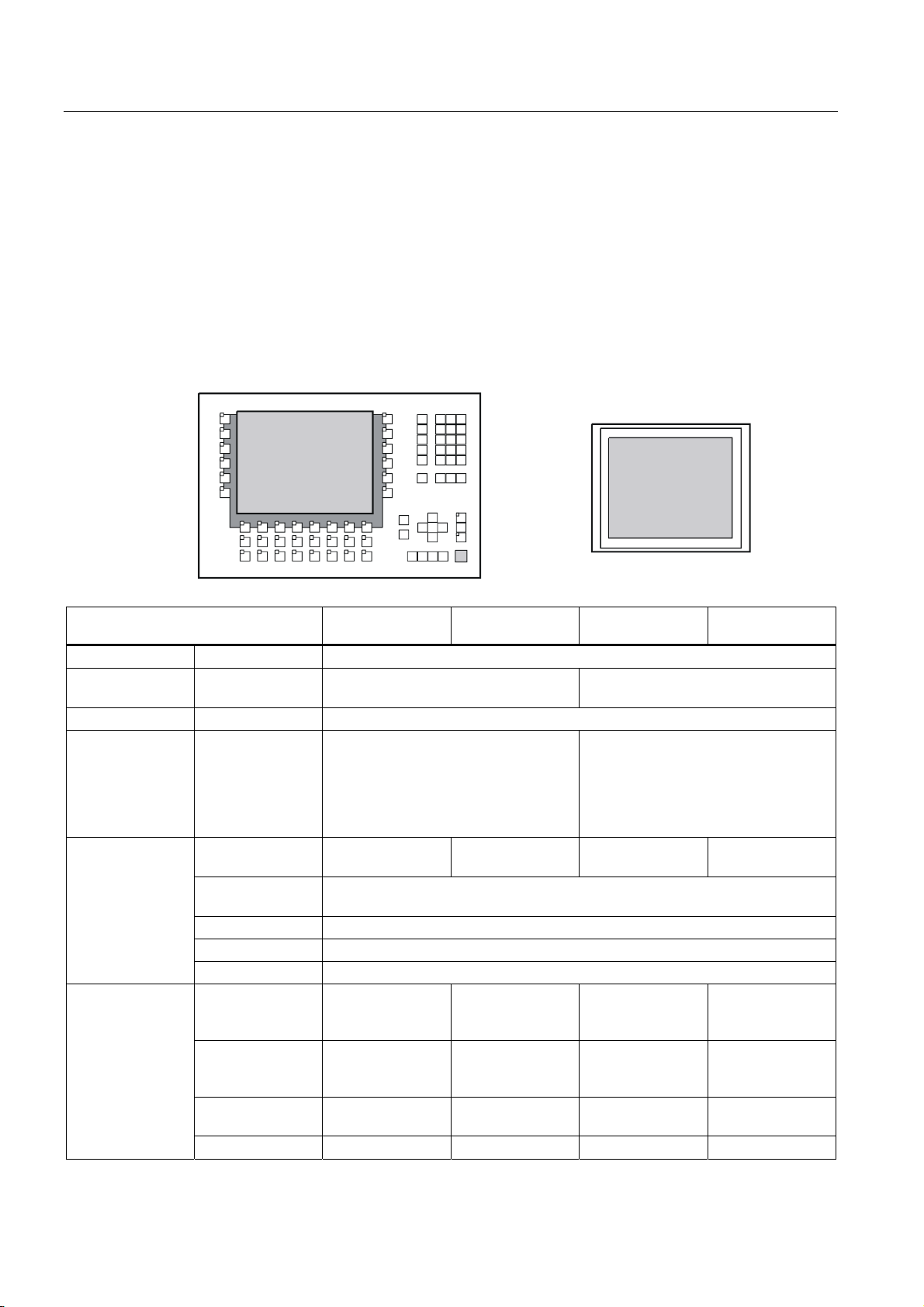
1.4 Features
Overview of MP 270B 10", OP 270 10" and TP 270 10"
Features MP 270B 10" Keys MP 270B 10"
Touch
Processor Type RISC CPU
Memory for
configuration
Software Operating system Microsoft Windows CE
Interfaces Interfaces for
Color display
Membrane
keyboard
Capacity (max.) 4 MB 2 MB
• 2 x RS 232, 1 x RS 422, 1 x RS 485
connecting PLC,
PC/PU, printer,
network, external
mouse and
keyboard
Type TFT LCD TFT LCD with
Active screen
diagonals
Resolution (pixels) 640 x 480
Possible colors 256
Back-lighting CCFL tubes
System keys with
dedicated
functions
Softkeys with
configurable
functions
Those for local
assignment
Softkey labeling With labeling strips - With labeling strips -
• 1 x PC card slot
• 1 x CF card slot
• 1 x USB
• 1 x Ethernet (RJ45)
touch panel
38 (3 with LEDs) - 38 (3 with LEDs) -
36 (28 with LEDs) - 36 (28 with LEDs) -
20 (12 with LEDs) - 20 (12 with LEDs) -
OP 270 10" TP 270 10"
• 2 x RS 232, 1 x RS 422, 1 x RS 485
• 1 x CF card slot
• 1 x USB
STN LCD STN LCD with
10,4 "
touch panel
TP 270, OP 270, MP 270B (WinCC flexible)
1-4 Operating Instructions, Edition 03/2004, 6AV6691-1DD01-0AB0
Overview
1.4 Features
Features MP 270B 10" Keys MP 270B 10"
Touch
Acoustic
acknowledgement
Special features
In the case of
touch control
DP direct keys
(touch buttons as
I/O periphery)
DP direct keys
(keys as I/O
periphery)
External memory
extension for
recipes, logs and
alarms etc.
Slot for PC card x x - -
Slot for CF card x x x x
- x - x
- x - x
x - x -
x x x x
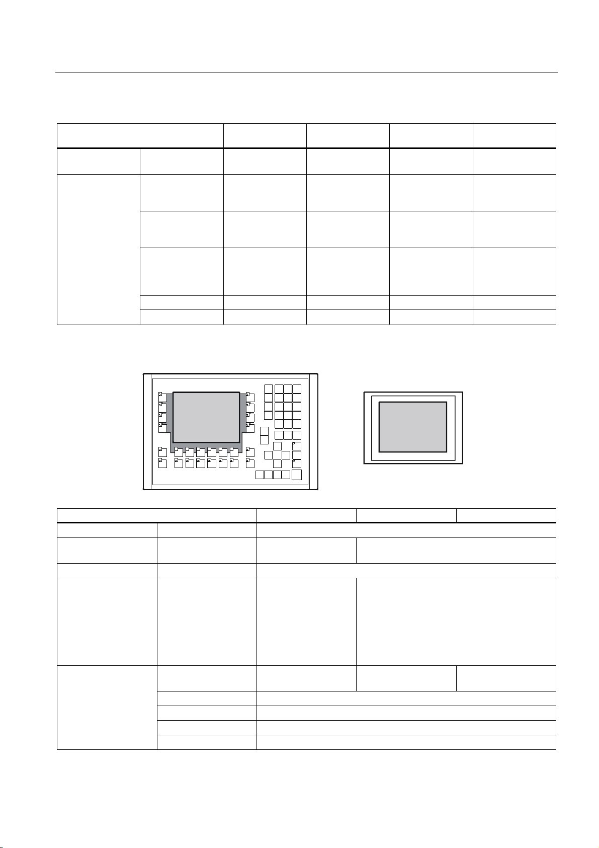
Overview of MP 270B 6" Touch, OP 270 6" and TP 270 6"
OP 270 10" TP 270 10"
Features MP 270B 6" Touch OP 270 6" TP 270 6"
Processor Type RISC CPU
Memory for
configuration
Software Operating system Microsoft Windows CE
Interfaces Interfaces for
Color display
TP 270, OP 270, MP 270B (WinCC flexible)
Operating Instructions, Edition 03/2004, 6AV6691-1DD01-0AB0
Capacity (max.) 4 MB 2 MB
• 2 x RS 232, 1 x RS
connecting PLC,
PC/PU, printer,
network, external
mouse and keyboard
Type TFT LCD with touch
Active screen diagonal 5,7 "
Resolution (pixels) 320 x 240
Possible colors 256
Back-lighting CCFL tubes
422, 1 x RS 485
• 1 x PC card slot
• 1 x CF card slot
• 1 x USB
• 1 x Ethernet
(RJ45)
panel
• 2 x RS 232, 1 x RS 422, 1 x RS 485
• 1 x CF card slot
• 1 x USB
CSTN LCD CSTN LCD with touch
panel
1-5

Overview
1.4 Features
Features MP 270B 6" Touch OP 270 6" TP 270 6"
Membrane keyboard
Acoustic
acknowledgement
Special features
System keys with
dedicated functions
Softkeys with
configurable functions
Those for local
assignment
Softkey labeling - System-specific with
In the case of touch
control
DP direct keys (touch
buttons as I/O
periphery)
DP direct keys (keys
as I/O periphery)
External memory
extension for recipes,
logs and alarms etc.
Slot for PC card x -
Slot for CF card x x
- 36 (3 with LEDs) -
- 24 (18 with LEDs) -
- 14 (8 with LEDs) -
-
labeling strips
x - x
x - x
- x -
x x
Further information
The creation of projects for HMI devices and functions for the configuration software is
described in detail in the "WinCC flexible" user manual and in the WinCC online help.
Information on connecting the HMI device to the PLC is provided in the "WinCC flexible
Communication" user manual.
The "Readme.chm" file on the WinCC flexible CD contains the most current information
which could not be included in the manuals and online help due to time constraints.
TP 270, OP 270, MP 270B (WinCC flexible)
1-6 Operating Instructions, Edition 03/2004, 6AV6691-1DD01-0AB0
Overview
1.5 Functional scope
1.5 Functional scope
General information
The following table summarizes the range of functions provided by the HMI device. The
numeric values are maximum values which the HMI device is capable of managing. These
values are not cumulative. It is not possible to simultaneously configure 4000 alarms and
300 screens each with 400 tags per screen.
The defined values are also limited by the size of the configuration memory.
Function MP 270B Keys MP 270B
Touch
Alarms
ALARM_S Display S7 alarms x
Alarm logging Output to printer x
Volatile alarm buffer
Number 4000
Discrete alarms Yes
Analog alarms Yes
Indicators Alarm line/Alarm window/alarm view
Process values in alarm
text
Length of the alarm text 80 characters (dependent on font)
Color-coding of different
alarm states
Warning alarms x
Error alarms
Type of display
Acknowledge individual
alarms
Acknowledge several
error alarms
simultaneously (group
acknowledgement)
Alarm buffer capacity 512 alarm events, circular buffer
View alarms x
Delete x
Print x
Time of occurrence Date/time Alarm acquisition
Alarm events Arrived, departed, acknowledged
First/last, selectable
16 acknowledgment groups
OP 270 TP 270
8
x
x
x
TP 270, OP 270, MP 270B (WinCC flexible)
Operating Instructions, Edition 03/2004, 6AV6691-1DD01-0AB0
1-7
Overview
1.5 Functional scope
Function MP 270B Keys MP 270B
Touch
Screens
Tags Number 2048
Limit value monitoring Input/output x
Conversion functions Input/output x
Number 500
Text objects 10000 text elements
Fields per screen 200
Tags per screen 200
Operating elements
Operator prompting
Help text
Animation
Unhide/hide objects
Softkey icons
Tab order
LEDs in softkeys
Fixed window x
• Button
• Switch
• I/O field
• Graphic I/O field
• Symbolic I/O field
• Alarm indicator
• Alarm view
• Alarm window
• Recipe view
• Bar
• Trend view
• Slider control
• Gauge
• Date / time field
• Clock
• User view
• Status force
• Sm@rtClient view
• Symbol library
x
x
x
x
x
x
x
x
x
-
-
-
OP 270 TP 270
x
x
x
x
x
x
1)
x
x
x
-
-
-
TP 270, OP 270, MP 270B (WinCC flexible)
1-8 Operating Instructions, Edition 03/2004, 6AV6691-1DD01-0AB0

Overview
1.5 Functional scope
Help text
Logging
Lists
Print functions
Safety
Recipes
force)
Function MP 270B Keys MP 270B
Touch
Lines/characters 7/35 (dependent on font)
For alarms x
For screens x
For screen objects
I/O field
Symbolic I/O field
Graphic I/O field
Button
Switch
Hidden button
x
x
x
x
x
x
x
x
x
-
-
-
Alarms x
Tags x
Log type Circular/sequential log
Number of logs 20
Number of tags for
logging
Number of sequential
logs
Entries per log 500000, limited by storage medium
Memory location
• PC card
• CF card
• Ethernet
Number 500
Graphics lists 400
Text lists 500
Hardcopy of the screen
content, also in color
Direct alarm logging x
Freely configurable logs x
Number of user groups 50
No. of users 50
No. of authorizations 32
Number 300
Data records per recipe 500, limited by storage medium
Elements per recipe 1000
Recipe memory 64 KB (integr. Flash, expandable)
Number of languages 5 Online languages
Project languages (with
system alarms)
Chinese (simplified), Chinese (traditional), Czechoslovakian,
Danish, Dutch, English, Finnish, French, German, Greek,
Hungarian, Italian, Japanese, Korean, Norwegian, Polish,
Portuguese, Russian, Spanish, Swedish, Turkish
SIMATIC S5 x PU functions (status
SIMATIC S7 x
OP 270 TP 270
x
x
x
x
x
x
20
400
• CF card
• Ethernet (optional)
x
2)
x
x
x
-
-
-
2)
TP 270, OP 270, MP 270B (WinCC flexible)
Operating Instructions, Edition 03/2004, 6AV6691-1DD01-0AB0
1-9

Overview
1.5 Functional scope
Function MP 270B Keys MP 270B
Touch
Scheduler Trigger functions
cyclically or once
User-specific expansions
of functionality
Number of scripts 50
Connections 3) Number 6
OP 270 TP 270
x
x VBScript
1) Maximum total number for PowerTags and internal tags
2) Storage media refers to PC cards, CF cards and network drives
3) With SIMATIC S7
TP 270, OP 270, MP 270B (WinCC flexible)
1-10 Operating Instructions, Edition 03/2004, 6AV6691-1DD01-0AB0

Overview
1.6 Communication with PLCs
1.6 Communication with PLCs
The following tables list the PLCs which can be connected to the HMI device.
Table 1-1 Communication with SIMATIC PLCs
PLC MP 270B Keys MP 270B Touch OP 270 TP 270
SIMATIC S5 AS511 1)
SIMATIC S5 DP
SIMATIC S7–200 x
SIMATIC S7–300/400 x
SIMATIC 500/505 serial
SIMATIC 500/505 DP
SIMATIC HMI HTTP Protocol x
OPC 2) x -
SIMATIC WinAC x
SIMOTION x
x
x
x
x
1) Only via converter cable
2) Data exchange only via XML (connection to OPC-XML server)
Table 1-2 Communication with PLCs from other manufacturers
PLC MP 270B Keys MP 270B Touch OP 270 10"/OP 270
6"
Allen Bradley DF1
Allen Bradley DH485
LG GLOFA-GM x
Modicon MODBUS x
Mitsubishi FX
Mitsubishi Protocol 4
GE Fanuc SNP x
Omron Hostlink/Multilink x
x
x
x
x
TP 270 10"/TP 270
6"
TP 270, OP 270, MP 270B (WinCC flexible)
Operating Instructions, Edition 03/2004, 6AV6691-1DD01-0AB0
1-11
Overview
1.7 Options
1.7 Options
1.7.1 Hardware options
1.7.1.1 Backup battery
Function of the backup battery
The battery ensures that in the event of a power failure, the HMI device's internal hardware
clock continues to run. If no battery is available, the clock continues for approx. three days
as long as the HMI device was in operation for 6 to 8 hours, without interruption, beforehand.
The battery is not supplied with the HMI device.
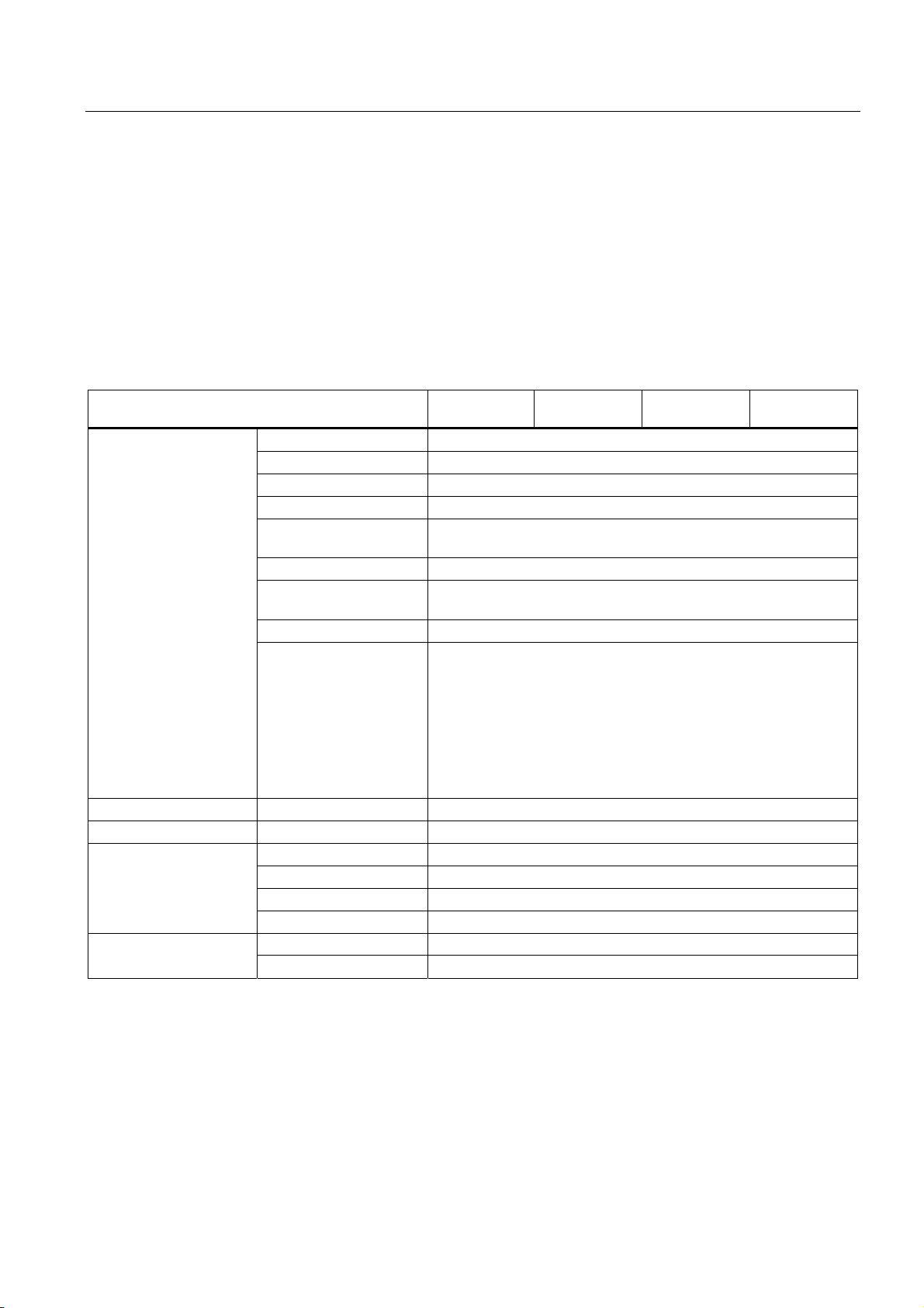
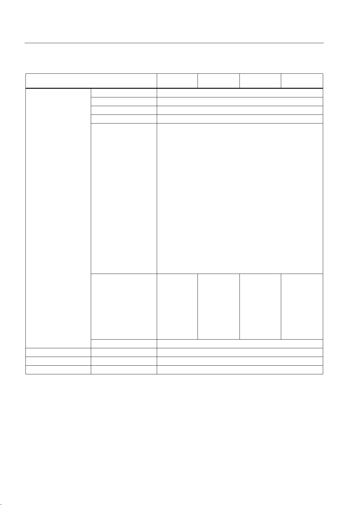
Installation in the MP 270B 10", TP 270 10" or OP 270 10"
1. Secure the battery with two cable ties to the back of the HMI device. The position is
indicated by an arrow in the following figures.
Figure 1-2 MP 270B 10" Keys / OP 270 10"
Figure 1-3 MP 270B 10" Touch / TP 270 10"
2. Insert the battery lead connector into the two-pin socket. The plug is coded to prevent
reversed poling.
TP 270, OP 270, MP 270B (WinCC flexible)
1-12 Operating Instructions, Edition 03/2004, 6AV6691-1DD01-0AB0
Overview
1.7 Options
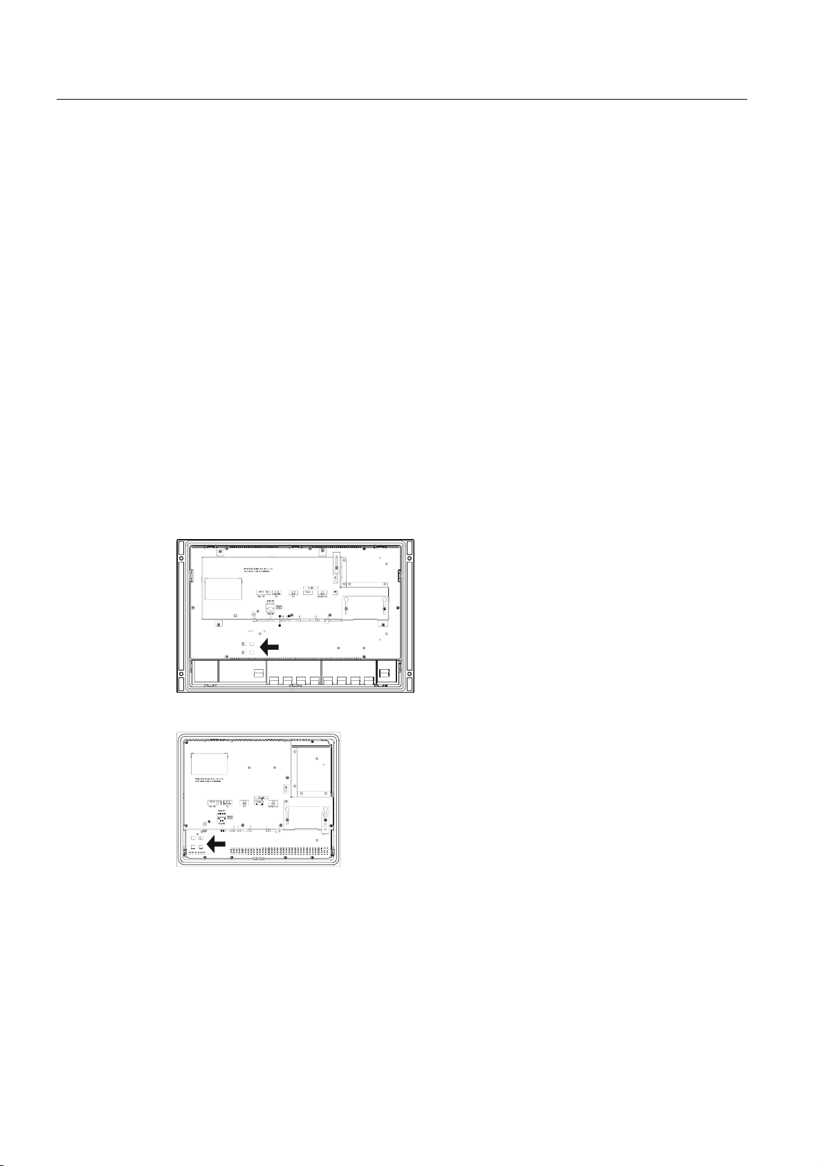
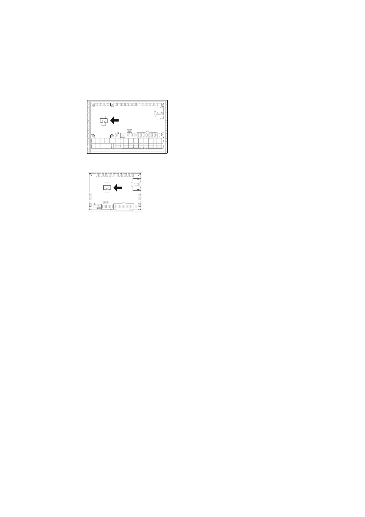
Assembly on MP 270B 6" Touch, TP 270 6" and OP 270 6"
1. Secure the battery to the back of the HMI device with one cable tie. The position is
indicated by an arrow in the following figures.
Figure 1-4 OP 270 6"
Figure 1-5 MP 270B 6" Touch / TP 270 6"
See also
2. Insert the battery lead connector into the two-pin socket. The plug is coded to prevent
reversed poling.
Replacing the optional backup battery (Page 11-3)
Interfaces (Page 4-6)
TP 270, OP 270, MP 270B (WinCC flexible)
Operating Instructions, Edition 03/2004, 6AV6691-1DD01-0AB0
1-13
Overview
1.7 Options
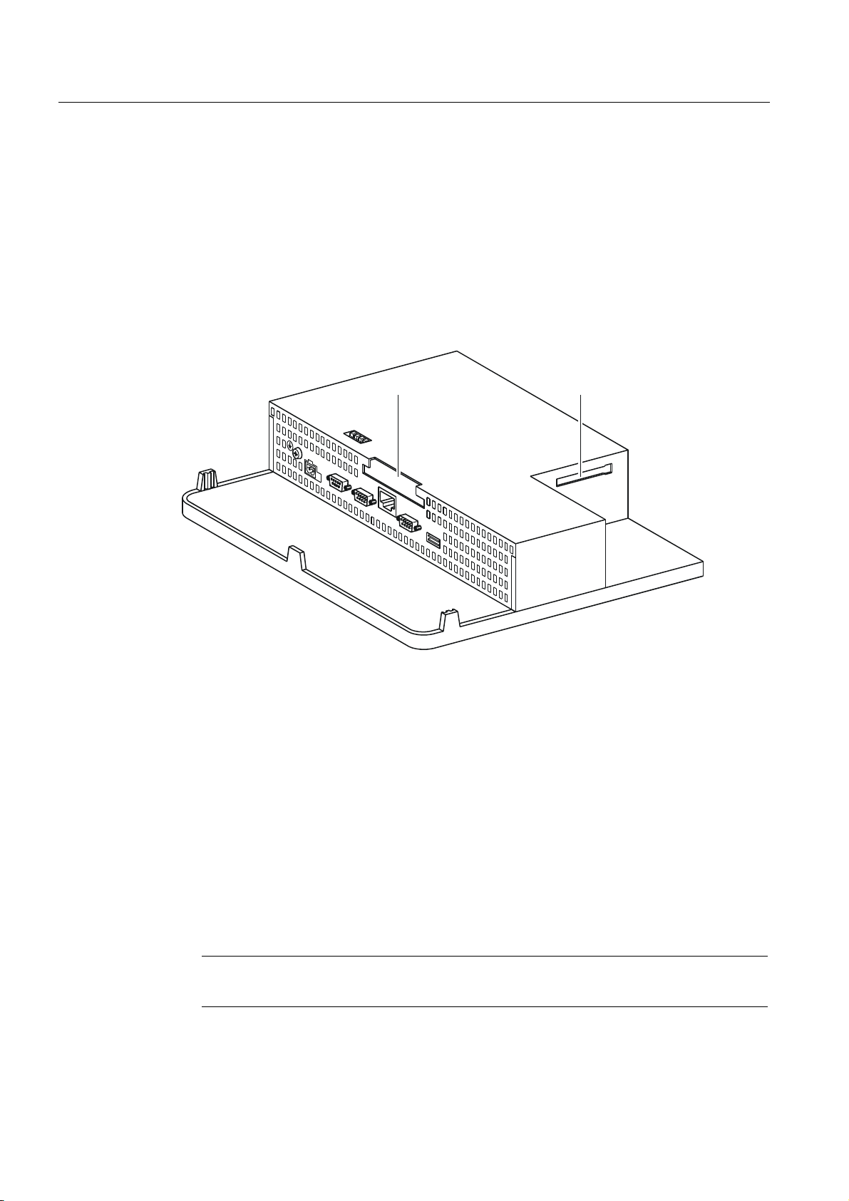
1.7.1.2 PC card / CF card
Purpose
Changeable PC cards and CF cards can be inserted in the two slots, Slot A and Slot B on
the back of the MP 270B. They are not supplied.
The TP 270 and OP 270 have only one slot for CF cards (Slot B).
Changeable memory cards can be used, for example, to store important process data or
execute a backup/restore of the internal flash memory.
Slot A Slot B
Cards supported
Figure 1-6 Position of the slots (example of MP 270B 10" Keys)
The HMI device supports standard cards which operate with a programming voltage of 5 V:
• Slot A (PC card) (type I and II) (for MP 270B only):
– ATA Flash card
– SRAM card
– NE2000-compatible Ethernet card
• Slot B (CF card) (type I):
– ATA Flash card
– NE2000-compatible Ethernet card
Caution
The current limitation is 300 mA per slot.
TP 270, OP 270, MP 270B (WinCC flexible)
1-14 Operating Instructions, Edition 03/2004, 6AV6691-1DD01-0AB0

Overview
1.7 Options
Remove memory card
Caution
Ensure that the HMI device does not access the memory card during the removal process.
Otherwise, the contents of the memory card will be fully destroyed.
1. Terminate access made by the HMI device to the memory card.
If the configuration engineer has defined an operating element linked to the
"CloseAllLogs" system function, press the element. Otherwise, press the operating
element linked to the "StopRuntime" system function in the configuration. This ends
runtime.
2. Wait unit the HMI device displays the loader.
Changeover to the loader may take several minutes depending on the size and number
of logs stored.
3. Remove the memory card.
Switch off the HMI device with memory card inserted
Caution
Always terminate the runtime software before switching off the voltage supply in order to
prevent loss of data.
1. Terminate runtime.
Press the operating element linked to the "StopRuntime" system function in the
configuration.
2. Wait unit the HMI device displays the loader.
Changeover to the loader may take several minutes depending on the size and number
of logs stored.
3. Switch off the power supply.
If the power supply is interrupted during normal operation, the HMI device checks the
memory card after power is restored and repairs any defect sectors.
See also
HMI device loader (Page 6-1)
TP 270, OP 270, MP 270B (WinCC flexible)
Operating Instructions, Edition 03/2004, 6AV6691-1DD01-0AB0
1-15

Overview
1.7 Options
1.7.2 Software options
1.7.2.1 Internet Explorer
Overview
The Internet Explorer supplied with the HMI device has been specially adapted to the
Windows CE operating system and has a restricted functional scope (Pocket Internet
Explorer). Only simple HTML pages, about 100 kb, can be displayed.
Prior to installation, use the system settings to set 1.5 Mb memory for the DRAM file system.
Caution
If too much memory is provided for the DRAM file system, runtime has too little working
memory available. Therefore, in the case of incorrect settings, there is no guarantee that the
runtime can run properly.
Caution
The operation of runtime together with the Internet Explorer can only be guaranteed when
the run-capable configuration (*.fwx) generated is a maximum of 2 Mb.
The installation of Internet Explorer is performed using the ProSave service tool or WinCC
flexible configuration software.
Files created in Internet Explorer, e.g. Favorites, are stored in the DRAM file system. The
DRAM file system is deleted when the unit is switched off. However, using the system
settings (OP Properties > Persistent Storage > Save Files), it is possible to backup the data
currently available in the DRAM file system to the Flash memory. When the device is started
up, the backup data is automatically restored.
If you remove the Internet Explorer, the files created from Internet Explorer must also be
deleted. To do this, delete the files in the DRAM file system using the standard Explorer.
Then backup the DRAM file system ("OP Properties > Persistent Storage > Save Files").
Reset the size of the DRAM file system to the preset value of 2 Mb.
Note
The initial configuration can be restored simply by updating the operating system.
See also
System (Page 6-15)
Update operating system (Page 7-18)
Transferring options (Page 7-22)
TP 270, OP 270, MP 270B (WinCC flexible)
1-16 Operating Instructions, Edition 03/2004, 6AV6691-1DD01-0AB0
 Loading...