

Siemens SIMATIC Mobile Client900RFN Operating Instructions Manual

Mobile Client900RXA
___________________
___________________
___________________
___________________
___________________
___________________
___________________
___________________
___________________
___________________
___________________
___________________
___________________
SIMATIC HMI
Customized automation
Mobile Client900RXA
Operating Instructions
07/2015
A5E36360099
Preface
Overview
1
Safety guidelines
2
Installing and connecting the
device
3
Parameter assignment of a
Mobile Client
4
Configuring the Mobile Client
and Connection box
5
Commissioning a project
6
Operating the project
7
Operating the mobile client
8
Device maintenance and
repair
9
Technical specifications
10
Technical support
A
Abbreviations
B
-AA
Siemens AG
Division Digital Factory
Postfach 48 48
90026 NÜRNBERG
GERMANY
A5E36360099-AA
Ⓟ
Copyright © Siemens AG 2015.
All rights reserved
Legal information
Warning notice system
DANGER
indicates that death or severe personal injury will result if proper precautions are not taken.
WARNING
indicates that death or severe personal injury may result if proper precautions are not taken.
CAUTION
indicates that minor personal injury can result if proper precautions are not taken.
NOTICE
indicates that property damage can result if proper precautions are not taken.
Qualified Personnel
personnel qualified
Proper use of Siemens products
WARNING
Siemens products may only be used for the applications described in the catalog and in the relevant technical
maintenance are required to ensure that the products operate safely and without any problems. The permissible
ambient conditions must be complied with. The information in the relevant documentation must be observed.
Trademarks
Disclaimer of Liability
This manual contains notices you have to observe in order to ensure your personal safety, as well as to prevent
damage to property. The notices referring to your personal safety are highlighted in the manual by a safety alert
symbol, notices referring only to property damage have no safety alert symbol. These notices shown below are
graded according to the degree of danger.
If more than one degree of danger is present, the warning notice representing the highest degree of danger will
be used. A notice warning of injury to persons with a safety alert symbol may also include a warning relating to
property damage.
The product/system described in this documentation may be operated only by
task in accordance with the relevant documentation, in particular its warning notices and safety instructions.
Qualified personnel are those who, based on their training and experience, are capable of identifying risks and
avoiding potential hazards when working with these products/systems.
Note the following:
documentation. If products and components from other manufacturers are used, these must be recommended
or approved by Siemens. Proper transport, storage, installation, assembly, commissioning, operation and
All names identified by ® are registered trademarks of Siemens AG. The remaining trademarks in this publication
may be trademarks whose use by third parties for their own purposes could violate the rights of the owner.
We have reviewed the contents of this publication to ensure consistency with the hardware and software
described. Since variance cannot be precluded entirely, we cannot guarantee full consistency. However, the
information in this publication is reviewed regularly and any necessary corrections are included in subsequent
editions.
for the specific
07/2015 Subject to change

Preface
Purpose of the operating instructions
Knowledge required
Scope of application of the document
Note
Observe the following points:
•
•
•
These operating instructions provide information based on the requirements defined by
DIN EN 62079 for mechanical engineering documentation. This information relates to the
place of use, transport, storage, mounting, use and maintenance.
These operating instructions are intended for the following user groups:
● Operators
Operators operate and monitor the system during the process control phase.
● Commissioning engineers
The commissioning engineer integrates the HMI device into the system and ensures the
operating capability of the HMI device for the process control phase.
● Service technicians
Service technicians rectify faults that occur during the process control phase.
● Maintenance technicians
Maintenance technicians carry out regular maintenance work during the process control
phase.
General knowledge of automation technology and process communication is needed to
understand the operating instructions.
This source document was written in German, the basis for the translations, and applies to
the following HMI devices:
● SIMATIC Mobile Client900RXA, article number 6AV6645-7CG00-2AA0
This document belongs to the device and will also be required for repeat commissioning.
Keep all supplied and supplementary documentation for the entire service life of the
device.
Make sure that the persons who require these documents have access to them.
Pass on all of these documents to the subsequent owner of the device.
Mobile Client900RXA
Operating Instructions, 07/2015, A5E36360099-AA
3
Preface
Figures
Style conventions
Representation type
Scope
<F1>, <Alt + P>
Keyboard actions
Note
Notes containing important information about the product and its use or a specific section of
the documentation to which you should pay particular attention.
Naming conventions
Item name
Term used in the document
Mobile Client all versions
Device, HMI device, Mobile Client, Mobile Panel
temperature range)
Mobile Client without Arctic extension
Non-arctic HMI device
This document contains figures of the described devices and the described software. The
figures can deviate from the particularities of the delivered device and the supplied software.
The following text notation will facilitate reading this manual:
"Add figure"
"File > Edit" Operating sequences, for example, menu commands, shortcut
Please observe notes labeled as follows:
The following terms are used in this document:
Mobile Client with Arctic extension (extended
• Terminology that appears in the user interface, for example
dialog names and buttons.
• Required inputs, for example, an IP address.
• Path information
menu commands.
Arctic HMI device
Mobile Client900RXA
4 Operating Instructions, 07/2015, A5E36360099-AA

Table of contents
Preface ................................................................................................................................................... 3
1 Overview................................................................................................................................................. 9
2 Safety guidelines ................................................................................................................................... 25
3 Installing and connecting the device ...................................................................................................... 31
1.1 Product description ................................................................................................................... 9
1.2 Design of the device ............................................................................................................... 10
1.3 Scope of delivery .................................................................................................................... 12
1.4 Accessories ............................................................................................................................. 12
1.4.1 Connecting cable .................................................................................................................... 12
1.4.2 Connection box ....................................................................................................................... 13
1.4.3 Wall-mounting bracket ............................................................................................................ 14
1.4.4 Wall-mounting bracket with cable holder ................................................................................ 15
1.4.5 Magnetic wall bracket ............................................................................................................. 16
1.4.6 Protective cover ...................................................................................................................... 18
1.4.7 Protective foil .......................................................................................................................... 18
1.4.8 Rubber strips ........................................................................................................................... 19
1.4.9 Touch pen ............................................................................................................................... 19
1.4.10 Storage media ......................................................................................................................... 20
1.5 The HMI device in the operating process ............................................................................... 20
1.6 Scope of functions with WinCC .............................................................................................. 21
1.7 Software add-ons .................................................................................................................... 23
1.8 Communication with controllers .............................................................................................. 24
2.1 General safety instructions ..................................................................................................... 25
2.2 Notes about usage .................................................................................................................. 28
2.3 Power supply .......................................................................................................................... 30
3.1 Preparing for installation ......................................................................................................... 31
3.1.1 Checking delivery .................................................................................................................... 31
3.1.2 Device identification data ........................................................................................................ 31
3.1.3 Mounting positions and type of fixation ................................................................................... 31
3.1.4 Preparing mounting of the connection box ............................................................................. 32
3.1.5 Preparing to mount the wall-mounting bracket ....................................................................... 32
3.2 Connection box and wall bracket ............................................................................................ 33
3.2.1 Mounting the connection box .................................................................................................. 33
3.2.2 Mounting the wall-mounting bracket ....................................................................................... 33
3.2.3 Mounting and using the magnetic wall-mounting bracket....................................................... 35
3.2.3.1 Mounting the magnetic wall bracket ....................................................................................... 35
3.2.3.2 Using the magnetic wall bracket ............................................................................................. 36
Mobile Client900RXA
Operating Instructions, 07/2015, A5E36360099-AA
5

Table of contents
4 Parameter assignment of a Mobile Client .............................................................................................. 45
3.3 Connecting the device ........................................................................................................... 37
3.3.1 Connecting the connection box .............................................................................................. 37
3.3.1.1 Connection sequence ............................................................................................................ 37
3.3.1.2 Connecting cables and replacing fuses ................................................................................. 38
3.3.1.3 Connecting the power supply ................................................................................................. 39
3.3.2 Connecting the mobile client .................................................................................................. 41
3.3.3 Connecting the USB mouse or USB keyboard for service purposes .................................... 42
3.4 Switching on and testing the HMI device ............................................................................... 43
4.1 Desktop and Start Center ...................................................................................................... 45
4.2 Operating the desktop, Start Center and Control Panel ........................................................ 46
4.3 Installed programs ................................................................................................................. 46
4.4 Security mode ........................................................................................................................ 47
4.4.1 Overview ................................................................................................................................ 47
4.4.2 Activating and deactivating temporary security mode ........................................................... 48
4.4.3 Using the HMI device in password-protected security mode ................................................. 49
4.5 Control Panel ......................................................................................................................... 50
4.5.1 Overview ................................................................................................................................ 50
4.5.2 Functions in the Control Panel ............................................................................................... 50
4.5.3 Operating the Control Panel .................................................................................................. 51
4.5.4 Display types for the screen keyboard ................................................................................... 52
4.5.5 Configuring operation ............................................................................................................. 54
4.5.5.1 Changing the screen settings ................................................................................................ 54
4.5.5.2 Configuring the screen keyboard ........................................................................................... 56
4.5.5.3 Setting the character repeat rate of the screen keyboard ..................................................... 57
4.5.5.4 Setting the double-click .......................................................................................................... 58
4.5.5.5 Calibrating the touch screen .................................................................................................. 59
4.5.5.6 Restarting the Mobile Panel ................................................................................................... 60
4.6 General settings ..................................................................................................................... 62
4.6.1 Regional and language settings............................................................................................. 62
4.6.2 Setting the date and time ....................................................................................................... 63
4.6.3 Changing password protection .............................................................................................. 64
4.6.4 Setting the screen saver ........................................................................................................ 66
4.6.5 Configuring transfer ............................................................................................................... 67
4.6.6 Setting the memory ................................................................................................................ 69
4.6.6.1 Displaying memory distribution .............................................................................................. 69
4.6.6.2 Setting the project storage location and start delay ............................................................... 70
4.6.7 Backing up registry information and temporary data ............................................................. 71
4.6.8 Changing the printer properties ............................................................................................. 72
4.6.9 Displaying general system properties .................................................................................... 73
4.6.10 Displaying information about the Mobile Panel ...................................................................... 74
4.7 Changing Internet settings ..................................................................................................... 75
4.7.1 Changing general Internet settings ........................................................................................ 75
4.7.2 Setting the proxy server ......................................................................................................... 76
4.7.3 Changing the privacy settings ................................................................................................ 77
4.7.4 Importing, displaying and deleting certificates ....................................................................... 78
4.8 Enabling NTP ......................................................................................................................... 80
Mobile Client900RXA
6 Operating Instructions, 07/2015, A5E36360099-AA

Table of contents
5 Configuring the Mobile Client and Connection box .............................................................................. 101
6 Commissioning a project ..................................................................................................................... 103
7 Operating the project ........................................................................................................................... 115
4.9 Configuring network operation ................................................................................................ 81
4.9.1 Overview ................................................................................................................................. 81
4.9.2 Entering the Mobile Panel computer name............................................................................. 83
4.9.3 Specifying the IP address and name server ........................................................................... 84
4.9.4 Specifying the logon data ....................................................................................................... 85
4.9.5 Configuring e-mail ................................................................................................................... 86
4.9.6 Configuring Telnet for remote control ..................................................................................... 88
4.10 Functions for service and commissioning ............................................................................... 88
4.10.1 Saving to external storage medium – backup ......................................................................... 88
4.10.2 Restoring from external storage medium – Restore ............................................................... 91
4.10.3 Restoring from external storage medium – Restore ............................................................... 93
4.10.4 Update operating system ........................................................................................................ 95
4.10.5 Setting a communication connection to the PLC .................................................................... 97
4.10.5.1 Overview ................................................................................................................................. 97
4.10.5.2 Changing the network configuration ....................................................................................... 97
5.1 Required configuration software ........................................................................................... 101
5.2 Configuring the device .......................................................................................................... 101
5.3 Configuring the Connection Box ........................................................................................... 101
6.1 Overview ............................................................................................................................... 103
6.2 Operating modes .................................................................................................................. 103
6.3 Using existing projects .......................................................................................................... 104
6.4 Data transmission options .................................................................................................... 105
6.5 Transfer ................................................................................................................................. 105
6.5.1 Setting the transfer mode ..................................................................................................... 105
6.5.2 Starting the transfer .............................................................................................................. 107
6.5.3 Testing a project ................................................................................................................... 108
6.6 Backup and restore ............................................................................................................... 109
6.6.1 Overview ............................................................................................................................... 109
6.6.2 Backing up and restoring data of the HMI device ................................................................. 110
6.7 Updating the operating system ............................................................................................. 111
6.7.1 Updating the operating system ............................................................................................. 111
6.7.2 Updating the operating system of the HMI device ................................................................ 111
6.8 Managing add-ons and license keys .................................................................................... 113
6.8.1 Transferring license keys ...................................................................................................... 113
7.1 Overview ............................................................................................................................... 115
7.2 Setting the project language ................................................................................................. 116
7.3 Entering and modifying the value, date and time ................................................................. 117
7.4 Operating the Sm@rtClient view .......................................................................................... 119
7.5 Displaying infotext ................................................................................................................. 121
7.6 Closing the project ................................................................................................................ 122
Mobile Client900RXA
Operating Instructions, 07/2015, A5E36360099-AA
7

Table of contents
8 Operating the mobile client ................................................................................................................... 123
9 Device maintenance and repair ............................................................................................................ 131
10 Technical specifications ....................................................................................................................... 135
A Technical support................................................................................................................................. 151
B Abbreviations ....................................................................................................................................... 153
Glossary .............................................................................................................................................. 155
Index ................................................................................................................................................... 157
8.1 Holding and setting down the mobile client ......................................................................... 123
8.2 Special operating modes ..................................................................................................... 124
8.3 Using the override function .................................................................................................. 125
8.4 LED display .......................................................................................................................... 126
8.5 Switching the device on and off ........................................................................................... 129
8.6 Possible errors when powering on ....................................................................................... 130
9.1 Cleaning the device ............................................................................................................. 131
9.2 Spare parts and repairs ....................................................................................................... 132
9.3 Recycling and disposal ........................................................................................................ 132
9.4 Maintenance application ...................................................................................................... 132
10.1 Certificates and approvals ................................................................................................... 135
10.2 Directives and declarations .................................................................................................. 136
10.2.1 Electromagnetic compatibility .............................................................................................. 136
10.2.2 ESD guideline ...................................................................................................................... 138
10.3 Dimension drawings ............................................................................................................. 140
10.3.1 Mobile client ......................................................................................................................... 140
10.3.2 Connection box .................................................................................................................... 141
10.3.3 Wall-mounting bracket ......................................................................................................... 142
10.3.4 Magnetic wall bracket .......................................................................................................... 143
10.4 Specifications ....................................................................................................................... 144
10.4.1 Technical specifications Mobile Client ................................................................................. 144
10.4.2 Technical specifications Connection Box ............................................................................ 145
10.4.3 Technical specifications of the wall-mounting brackets ....................................................... 146
10.4.4 Ambient conditions for transport and storage ...................................................................... 146
10.4.5 Ambient conditions during operation ................................................................................... 147
10.5 Contact assignment of the USB port.................................................................................... 149
A.1 Service and support ............................................................................................................. 151
A.2 Problem solving.................................................................................................................... 152
Mobile Client900RXA
8 Operating Instructions, 07/2015, A5E36360099-AA

1
1.1
Product description
The SIMATIC Mobile Client900RFN is a portable HMI device with a rugged and ergonomic
design. A high-performance processor and Ethernet capability mean the device is excellently
suited to a wide range of uses. The device is lightweight and robust, has an easy-to-read
display and can be operated by both left-handed and right-handed users.
The device also has the following additional features:
● Ethernet, integrated with connecting cable
● 9" TFT screen with color depth of 24 bits
● USB port for service purposes
● Heating system
The device heats up, if necessary, and keeps the internal temperature within the optimum
temperature range for as long as the heat output permits.
The SIMATIC Mobile Client connection box, connection box for short, is designed to be
mounted to the wall of the control cabinet. It provides the power supply and control system
connections in the control cabinet. The device is connected to the connection box with a
connecting cable.
The device is used as a mobile handheld terminal. The connecting cable can be easily
connected and disconnected at both the connection box and the handheld terminal. The
device enables you to use text- or graphic-based projects even more efficiently for simple
and medium-complexity operator control and monitoring tasks on machines and systems.
Mobile Client900RXA
Operating Instructions, 07/2015, A5E36360099-AA
9
Overview
Area of application
Note
Please observe the relevant requirements and safety meas
of use.
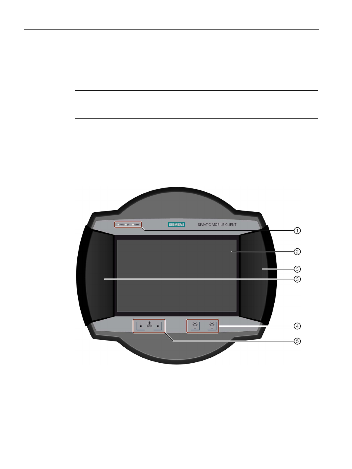
1.2
Design of the device
Front view
①
LED display
②
Display with touch screen
③
Handle
④
Button for brightness control
⑤
On/off button, two present
1.2 Design of the device
The device is intended for uses ranging from operation and monitoring, parameter
assignment, and commissioning to troubleshooting for industrial systems, in particular wind
turbines.
ures for the application and place
Mobile Client900RXA
10 Operating Instructions, 07/2015, A5E36360099-AA
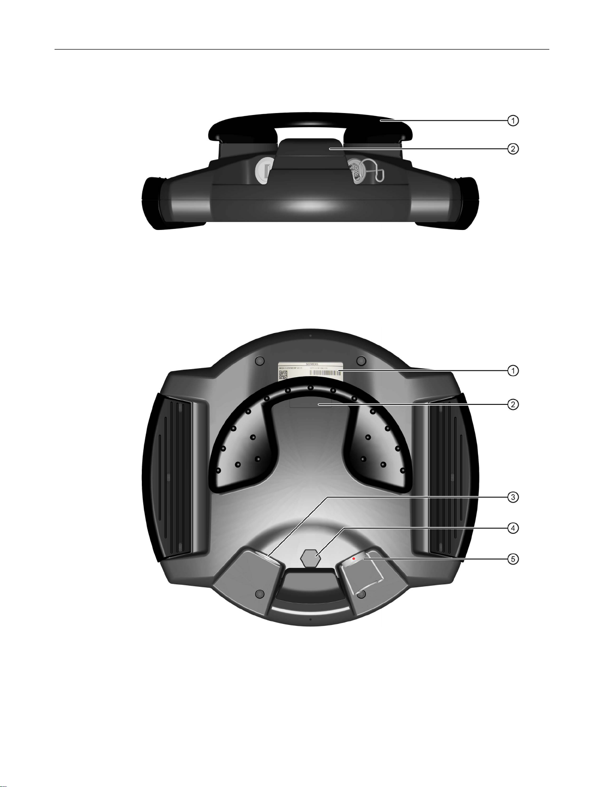
Overview
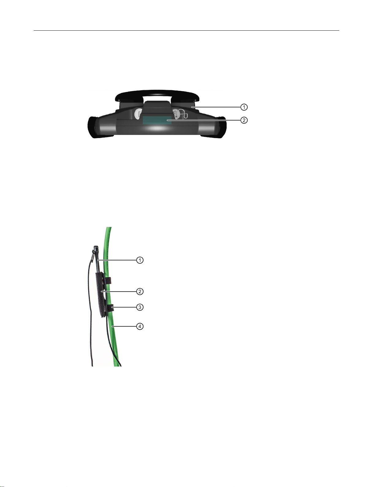
Bottom view
①
Handle
②
Stand
Rear view
①
Rating plate
②
Space for customized rating plate
③
USB port for service purposes
④
Pressure compensation valve
⑤
Port for connecting cable, with locking clip
1.2 Design of the device
The supporting surfaces of the handle and stand are made of anti-slip material.
Mobile Client900RXA
Operating Instructions, 07/2015, A5E36360099-AA
11

Overview
Note
The device ensures a degree of protection of IP65 even without the connecting cable
plugged in.
1.3
Scope of delivery
1.4
Accessories
1.4.1
Connecting cable
①
Circular connector, female connector for connection to the device
②
Circular connector, male connector for connection to the connection box
1.3 Scope of delivery
● 1 × HMI device
● 1 × packaging
Packaging is used for shipping and protection of the device. You can reuse the packaging
if you are returning the device.
Accessories are not included with the device. You can order accessories by entering the
corresponding article number at the following link:
Industry Mall (https://mall.industry.siemens.com
The connecting cable connects the device with the connection box:
)
Mobile Client900RXA
12 Operating Instructions, 07/2015, A5E36360099-AA

Overview
Length
Article number
Functional status
5 m
6AV6645-7CY03-1WP0
FS 02
15 m
6AV6645-7CY05-1WP0
FS 02
1.4.2
Connection box
①
Screws for fixing the connection box
②
Socket for the connecting cable
③
Locking bracket for the circular connector
④
Connecting cable
⑤
Attach
Article number:
Note
IP65 can only be guaranteed for the
1.4 Accessories
The connecting cable is available in the following lengths:
10 m 6AV6645-7CY04-1WP0 FS 02
The connecting cable is an industrial cable and is therefore resistant to many solvents and
lubricants. The flexural strength of the connecting cable is geared to the actual usage
conditions.
The connection box supplies power to the device and connects it to the Ethernet network.
A mechanical foolproofing device means that only the correct connecting cable circular
connector can be plugged into the connection box.
Mobile Client900RXA
Operating Instructions, 07/2015, A5E36360099-AA
ment for cable ties for strain relief
6AV6645-7CX06-1WP0
connection box when the connecting cable is attached.
13

Overview
1.4.3
Wall-mounting bracket
①
②
1.4 Accessories
The scope of delivery of the connection box includes:
● 1 × connection box
● 1 x accessory pack with the following contents:
– 4 M5 × 8 screws
– 1 mains terminal for the power supply
● 1 × Product Information
The wall bracket ensures secure fastening of the Mobile Panel during stationary operation.
Hook for the grip on the HMI device
Screw flange
The wall bracket is not included with the HMI device. The wall bracket is available with order
number 6AV6574-1AF04-4AA0.
Mobile Client900RXA
14 Operating Instructions, 07/2015, A5E36360099-AA
Overview
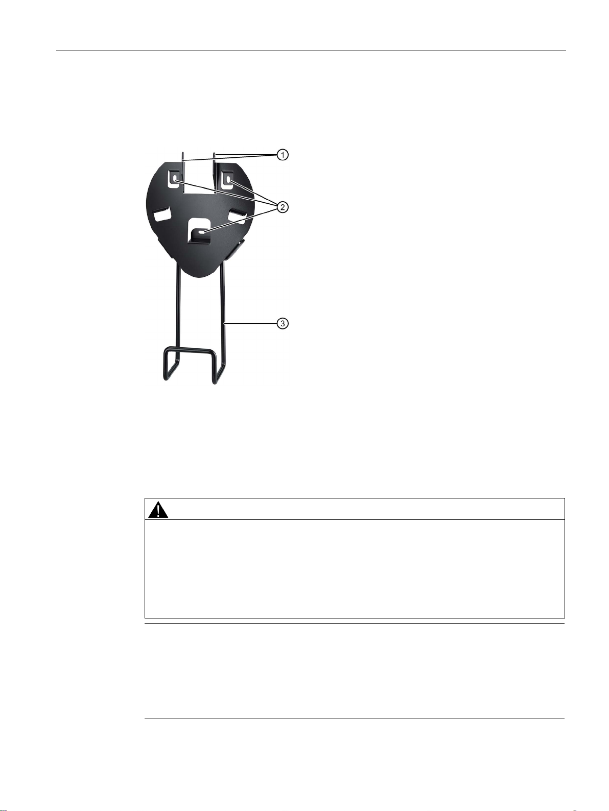
1.4.4
Wall-mounting bracket with cable holder
①
Hooks
You attach the handle of the Mobile Client to the hooks.
②
Mounting holes
③
Holder for the connecting cable
Article number:
CAUTION
Risk of injury when device drops
Note
The wall bracket is designed for fixed used and is always to be screwed to the wall.
•
•
•
1.4 Accessories
The wall bracket is used as a secure holder for the device during stationary operation and to
store the device when it is not in use.
6AV6645-7CX04-1WP0
The device can fall out of the wall bracket even when handled carefully.
• Never stand below the fitted wall bracket.
• The wall bracket is permitted for indoor use only.
• Do not mount the wall bracket on doors or covers.
• Do not fit the wall bracket anywhere where the device may fall out of the bracket.
The wall bracket should not be used to store tools or for other purposes.
Ensure that the wall bracket is used correctly. If the wall bracket is not in use, it should be
stored in a suitable location.
Make sure that no one can trip over the cable and cause the device to fall.
Mobile Client900RXA
Operating Instructions, 07/2015, A5E36360099-AA
15
Overview
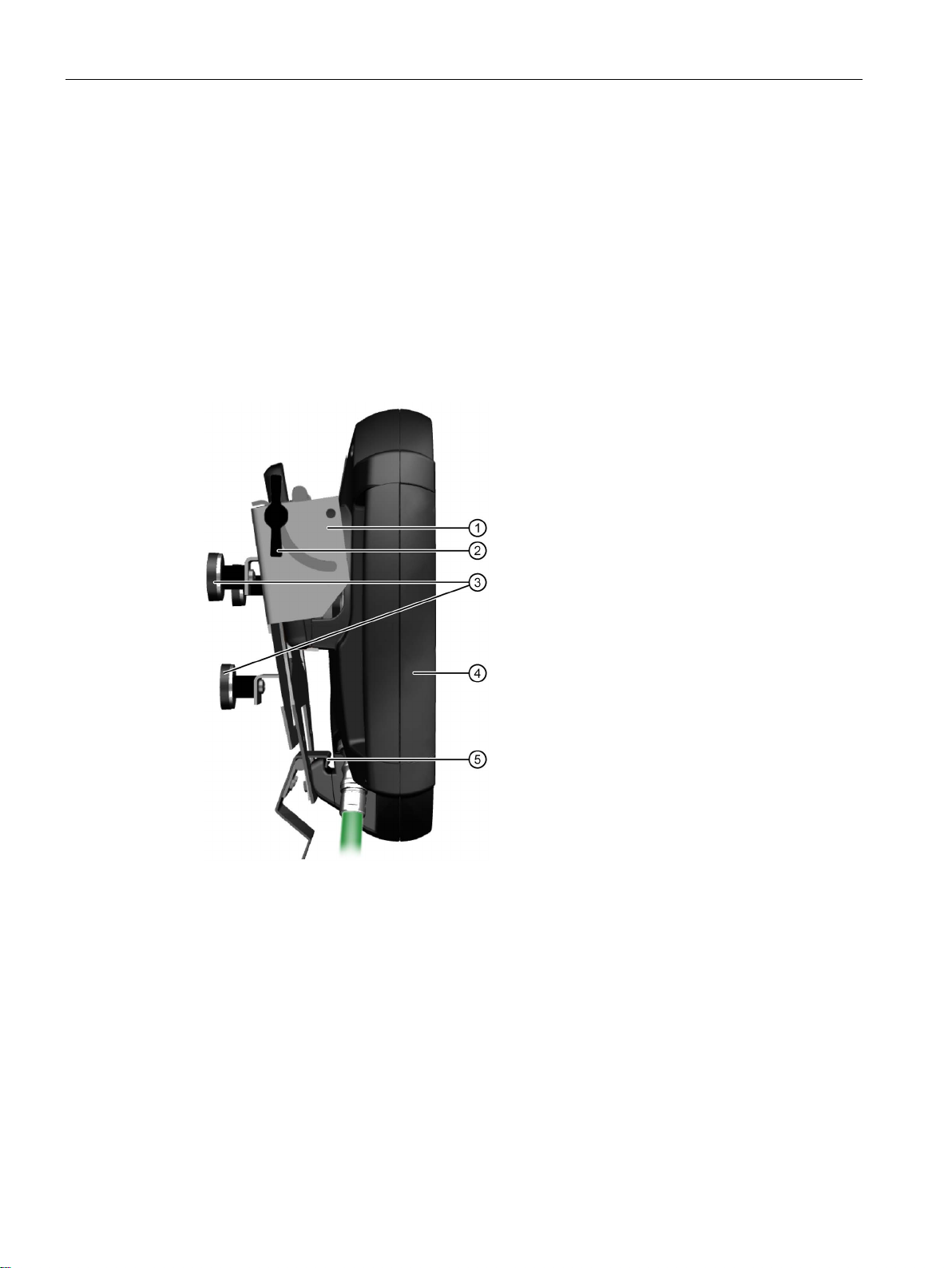
1.4.5
Magnetic wall bracket
①
Joint to set the inclination of the device
②
Wing screw to secure the inclination of the device
③
Magnets
④
Mobile Client
⑤
Locking hook
Article number:
1.4 Accessories
The magnetic wall bracket provides a safe hold for the SIMATIC Mobile Client when used in
stationary mode.
The magnetic wall bracket is equipped with magnets for permanent or temporary mounting
on ferromagnetic surfaces. The following applies to the magnetic holding power:
● Under normal circumstances, the wall bracket can be removed from the surface without
tools.
● When the wall bracket is used as intended, there is no danger of it falling unintentionally
with the HMI device.
The magnetic wall bracket features a retaining mechanism for the HMI device.
Mobile Client900RXA
16 Operating Instructions, 07/2015, A5E36360099-AA
6AV6645-7CX05-1WP0
Overview
Safety information on the magnetic wall bracket
CAUTION
Risk of injury when device drops
Risk of injury or damage from magnetic fields
Note
•
•
•
Adjustable inclination
CAUTION
Tighten the wing screws sufficiently
1.4 Accessories
The magnetic wall bracket should be regarded as a suspended load and can fall. However,
under normal circumstances and if handled properly, the magnetic wall bracket is designed
in such a way that there is no risk of the wall bracket and device unintentionally falling and
the wall bracket can be taken down without tools.
In the case of improper locking, the device could fall out of the wall bracket.
• Never stand below the fitted wall bracket.
• Do not mount the wall bracket overhead or in places where the wall bracket or the
device held in it could fall.
• The wall bracket is permitted for indoor use only.
• Do not mount the wall bracket on doors or covers.
• The magnetic holding power is affected by the material, thickness and structure of the
mounting surface. Ensure that the holding power at the mounting location is sufficient. If
necessary, choose a different mounting location.
Strong magnetic fields attract magnetic parts and damage or destroy electromagnetic
elements and devices. This also applies to pacemakers.
• Do not bring any iron parts (tools, nails, knives) into the vicinity of the magnets.
• Keep electronic devices and magnetic data carriers away from the magnets.
• Do not process the magnets mechanically, for example, by sawing or drilling.
• Keep the magnets away from open heat and flames.
The wall bracket should not be used to store tools etc.
Ensure that the wall bracket is used correctly. If the wall bracket is not in use, it should be
stored in a suitable location.
Make sure that no one can trip over the cable and cause the device to fall.
The inclination can be adjusted in the range from almost parallel to almost perpendicular to
the mounting surface. To adjust the inclination, loosen the wing screws located on both sides
of the wall bracket. With very large inclinations, the device cannot be removed from the wall
bracket. In this case, reduce the inclination in order to remove the device safely from the wall
bracket.
Loosen the wing screws only when you wish to adjust the inclination. Afterwards, tighten
the two wing screws. Check that the wing screws and the device are tightly in place.
Mobile Client900RXA
Operating Instructions, 07/2015, A5E36360099-AA
17
Overview
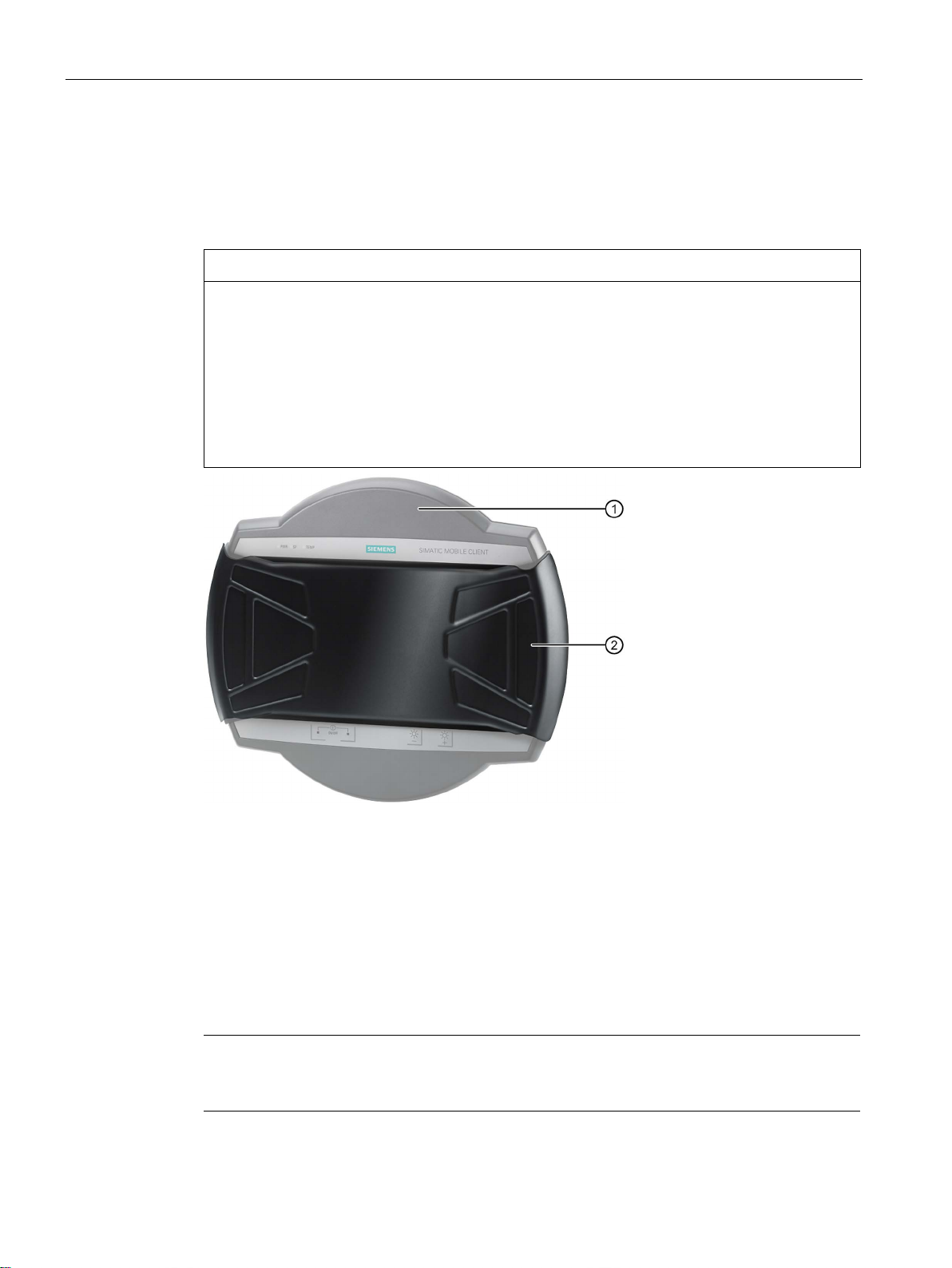
1.4.6
Protective cover
NOTICE
Overheating
Damage to the touch screen
①
Device
②
Protective cover
Article number:
1.4.7
Protective foil
Article number:
Note
Particles of dirt can scratch the touch screen when you attach the protective sheet. Clean the
touch screen before attaching the protective sheet.
1.4 Accessories
The protective cover provides mechanical protection of the display and is attached to both
handles. It protects the device from being damaged when transported, for example, in a tool
bag together with other tools.
If you use the protective cover when the HMI device is on, the device may overheat.
Make sure the HMI device is off before you fit the protective cover.
Particles of dirt can scratch the touch screen when you attach the protective cover.
Clean the touch screen before attaching the protective cover or use a protective sheet
according to chapter "Protective foil (Page 18)".
Mobile Client900RXA
18 Operating Instructions, 07/2015, A5E36360099-AA
The protective sheet prevents the touch screen getting scratched or dirty.
The set contains 10 protective sheets.
6AV6645-7CX02-1WP0
6AV6645-7CX07-1WP0
Overview
1.4.8
Rubber strips
①
Device
②
3 rubber strips
Article number:
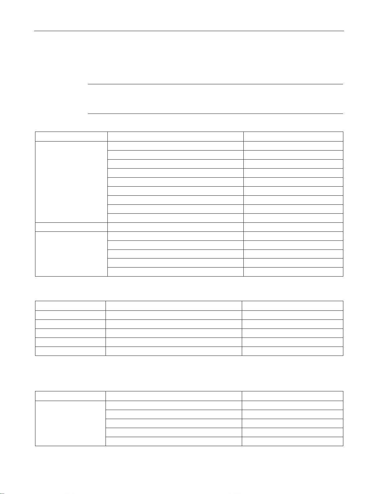
1.4.9
Touch pen
①
Touch pen
②
Holder
③
Velcro strap
④
Connecting cable
Article number:
1.4 Accessories
The rubber strips prevent the device from slipping. You can also use rubber strips to angle
the device, for example.
The touch pen makes it easier to operate the touch screen. The touch pen is to be attached
to the connecting cable.
6AV6645-7CX01-1WP0
Mobile Client900RXA
Operating Instructions, 07/2015, A5E36360099-AA
6FC5348-0AA08-4AA0
19

Overview
1.4.10
Storage media
Name
Article number
USB flash drive 8 GB
6ES7648-0DC50-0AA0
1.5
The HMI device in the operating process
1.5 The HMI device in the operating process
The HMI device is part of the operating process. Operation is based on two-way
communication between the HMI device and the PLC. The following figure shows an
exemplary system design.
The HMI device is used for monitoring or controlling the operating process. The controller in
turn supplies the results of the operating process, which are displayed on the Mobile Client.
Mobile Client900RXA
20 Operating Instructions, 07/2015, A5E36360099-AA
Overview
1.6
Scope of functions with WinCC
Note
The specified values are maximum values of the individual objects. Simultaneous use of
multiple objects with their maximum value can lead to problems in the active project.
Alarms
Object
Specification
Configuration
Number of discrete alarms
4000
Number of analog alarms
200
Alarm length
80 characters
Number of tags / process values in an alarm
Max. 8
Number of alarm classes
32
Display
Alarm window, alarm view
Acknowledge error alarm individually
Yes
Edit alarm
Yes
Alarm indicator
Yes
ALARM_S
Display S7 alarms
Yes
Alarm buffer capacity
1024
View alarm
Yes
Print alarms line by line
Yes
Tags, values and lists
Object
Specification
Configuration
Limit value monitoring
Input/output
Yes
Linear scaling
Input/output
Yes
Text lists
Number
500 1
Graphics lists
Number
500 1
1
The maximum total of text and graphics lists is 500.
Screens
Object
Specification
Configuration
Number
500
Objects per screen
400
Tags per screen
400
Complex objects per screen (for example, bars)
20
Template
Yes
1.6 Scope of functions with WinCC
The tables below show the objects that can be integrated in a project.
Alarms
Alarm buffer, retentive
Simultaneously queued alarm events 500
Delete alarm buffer Yes
Tags Number 2048
Screens
Mobile Client900RXA
Operating Instructions, 07/2015, A5E36360099-AA
21
Overview
Recipes
Object
Specification
Configuration
Number
300
Entries per data record
1000
Recipe memory
256 KB
1
The number of recipe data records may be restricted by the capacity of the storage medium.
Logs
Note
The HMI devices are suitable for the logging of relatively small volumes of data.
Manage the data in several adjacent logs in a segmented circular log. The use of a large
circular log has a negative effect on performance.
Object
Specification
Configuration
Number of logs
50
Number of partial logs in a segmented circular log
400
Entries per log 1
20000
Filing format
CSV with ANSI character set, RDB, TXT
1
The number of entries in the log may be restricted by the capacity of the storage medium.
Safety
Object
Specification
Configuration
Number of users
50
Number of authorizations/user permissions
32
Infotexts
Object
Specification
Configuration
Length (no. of characters)
320 (depending on font)
For alarms
Yes
For screens
Yes
invisible button)
1.6 Scope of functions with WinCC
Recipes
Data records per recipe 500
Logs
Storage location 1
• USB storage medium
• Network drive
Storage location
• USB storage medium
• Network drive
User view Number of user groups 50
Infotexts
For screen objects (e.g. I/O field, switch, button,
Mobile Client900RXA
22 Operating Instructions, 07/2015, A5E36360099-AA
Yes
Overview
Additional functions
Object
Specification
Configuration
Brightness setting
Yes
User-specific extension of the functionality
Yes
Graphic objects
Vector and pixel graphics
Yes
Trends
Number
300
Task planner
Number of tasks
48
Text objects
Number
40000
PROFIBUS DP direct keys
No
PROFINET IO direct keys
No
1
For HMI devices with touch screen only
1.7
Software add-ons
Add-on
Description
you to set up communication between different HMI systems.
for recording operations in an audit trail and electronic signature.
connected via the USB port.
Microsoft PDF Viewer 3
Microsoft PDF Viewer enables you to display PDF documents.
all HMI device print options.
1
2
3
Pre-installed; no license key is required for use
1.7 Software add-ons
Screen settings Touch screen calibration 1
Language change Number of languages per project 32
VBScript
Number of scripts 100
Direct keys
Yes
The following software add-ons are available for the HMI devices:
WinCC /Sm@rtServer 1 The WinCC /Sm@rtServer add-on enables you to access a remote
HMI device from the HMI device or PC via Ethernet. It also enables
WinCC /Audit 1 The WinCC /Audit add-on extends the HMI device to include functions
Uninterruptable
Powersupply (UPS)
with USB support 2
Microsoft Excel Viewer 3 Microsoft Excel Viewer enables you to display Excel documents.
Microsoft Word Viewer 3 Microsoft Word Viewer enables you to display Word documents.
Printer driver The printer driver option enables PostScript, HTML and PDF output for
Transferred with the project; a license key is required for use
Must be transferred as an option; no license key is required for use
When interfacing an uninterruptible power supply, the HMI device is
shut down in a controlled manner after a buffer time in the event of a
power failure. The HMI devices support SITOP DC UPS modules
Mobile Client900RXA
Operating Instructions, 07/2015, A5E36360099-AA
23
Overview
See also
1.8
Communication with controllers
Number of connections
Number of connections
Number of connection boxes
With bus connection
8
PLC that can be connected
PLC
HMI devices
SIMATIC S7-1500
Yes
SIMATIC S7-300
Yes
1.8 Communication with controllers
Printers approved for SIMATIC Panels and Multi Panels
)
)
(http://support.automation.siemens.com/WW/view/en/11376409
Printing with SIMATIC Comfort HMI devices
(http://support.automation.siemens.com/WW/view/en/58205602
The table below shows the number of connection boxes that can be connected.
With "SIMATIC HMI HTTP protocol" 8
The table below shows the number of PLCs that can be connected to the connection boxes.
Controllers that are not compatible with PROFINET services are marked with a footnote.
SIMATIC S7-400 Yes
SIMATIC HTTP protocol Yes
Mobile Client900RXA
24 Operating Instructions, 07/2015, A5E36360099-AA
2
2.1
General safety instructions
Safety regulations
WARNING
Hazards
WARNING
Voltage dips and memory changes
WARNING
Safety-related features after impact
Strictly observe all instructions in these operating instructions at all times. Otherwise,
hazardous situations can arise or the safety mechanisms in the HMI device can be
rendered ineffective.
Observe the safety and accident prevention instructions applicable to your application in
addition to the safety instructions given in this manual.
The configuration engineer for a machine or system PLC must take precautions so that an
interrupted program can be restarted normally after voltage dips or power failures.
Dangerous operating conditions must not occur, even temporarily.
If faults in the system can cause bodily injury or significant property damage, additional
measures must be taken outside of the system. These measures must also ensure safe
operating conditions in the system in the event of a fault.
The system's configuration engineer must take precautions to ensure that memory changes
that could lead to a dangerous situation can only be undertaken by authorized persons.
After a hard impact to the HMI device, check the safety-relevant features for functional
capability, for example in the event that the HMI device is dropped.
If the system is operated with the HMI device:
Ensure that current operation is only possible by means of the HMI device and not from any
other point on the system.
Mobile Client900RXA
Operating Instructions, 07/2015, A5E36360099-AA
25
Safety guidelines
Safety when working in and on electrical systems
Note
The safety regulations must be
carried out on electrical systems. The safety regulations must be applied in reverse order on
completion of all tasks on the electrical system.
Proper use
WARNING
Commissioning
High frequency radiation
Note
High
operating situations.
2.1 General safety instructions
Only authorized persons are allowed to work in or on electrical equipment. The following
safety regulations for prevention of electrical shock are valid:
1. Isolation of the system from power
2. Securing the system against restart
3. Verification of isolation from power at all poles
4. Grounding and shorting the system
5. Covering or fencing off adjacent live parts
applied in the aforementioned order before any work is
Identify the electrical system in accordance with valid safety regulations when working on
this system.
Observe the valid safety regulations of the respective country.
Commissioning of the HMI device is forbidden until it has been absolutely ensured that the
machine in which the HMI device is to be installed complies with Directive 98/37/EC or
Directive 2006/42/EC as ofDecember 29, 2009.
-frequency radiation from cellular phones, for example, can lead to undesirable
Mobile Client900RXA
26 Operating Instructions, 07/2015, A5E36360099-AA

Safety guidelines
Industrial Security
Disclaimer for third-party software updates
Notes on protecting administrator accounts
2.1 General safety instructions
Siemens offers products and solutions with Industrial Security functions that support the safe
operation of equipment, solutions, machines, devices and/or networks. They are important
components in a comprehensive Industrial Security concept. As a result the products and
solutions from Siemens are constantly evolving. Siemens recommends obtaining regular
information regarding product updates.
For safe operation of Siemens products and solutions appropriate protective measures (e.g.,
cell protection concept) must be taken and each component must be integrated in a
comprehensive Industrial Security concept, which corresponds with the current state of
technology. The products of other manufacturers need to be taken into consideration if they
are also used. You can find addition information on Industrial Security under
(http://www.siemens.com/industrialsecurity
Sign up for our product-specific newsletter to receive the latest information on product
updates. For more information, see under (http://www.siemens.de/automation/csi_en_WW
).
).
This product includes third-party software. Siemens AG only provides a warranty for
updates/patches of the third-party software, if these have been distributed as part of a
Siemens software update service contract or officially released by Siemens AG. Otherwise,
updates/patches are undertaken at your own risk. You can find more information about our
Software Update Service offer on the Internet at Software Update Service
http://www.automation.siemens.com/mcms/automation-software/en/software-update-
(
service).
A user with administrator privileges has extensive access and manipulation options in the
system.
Therefore, ensure there are adequate safeguards for protecting the administrator accounts
to prevent unauthorized changes. To do this, use secure passwords and a standard user
account for normal operation. Other measures, such as the use of security policies, should
be applied as needed.
Mobile Client900RXA
Operating Instructions, 07/2015, A5E36360099-AA
27

Safety guidelines
2.2
Notes about usage
Intended use of the Mobile Client
NOTICE
Wall bracket
Note
The device is not compatible with other system components, in particular not with those of
the SIMATIC Mobile Panel product family. You may only use the original
components defined here.
Industrial applications
2.2 Notes about usage
The SIMATIC Mobile Client is intended for uses ranging from operator control and
monitoring, parameter assignment, and commissioning to troubleshooting for industrial
systems, in particular wind turbines.
The system consists of the following components:
● Device
● Connecting cable
● Connection box
Ambient conditions for intended use:
● Industrial environment according to EN 61131-2:2007
● Indoor use protected from weather
● Ambient temperature range 0 ... 45 °C
The connection box is designed as bushing for installation in a control cabinet wall. The
device connecting cable can be easily unplugged and plugged back for moving the device
from one operating location to another.
Objects placed on the wall-mounting bracket may fall off and cause injury.
Do not use the wall-mounting bracket to hold other objects, for example tools.
The HMI device is designed for industrial applications. It conforms to the following standards:
● Emission requirements, EN 61000-6-4:2007
● Immunity requirements, DIN EN 61000-6-2:2005
system
Mobile Client900RXA
28 Operating Instructions, 07/2015, A5E36360099-AA
Safety guidelines
Use in residential areas
Note
The HMI device is not suitable for operation in residential areas. Operation of an HMI device
in resident
Mechanical and climatic conditions of use
NOTICE
Climatic factors at the place of use
WARNING
The product must not be used for the following applications
2.2 Notes about usage
ial areas can have a negative impact on radio and TV reception.
If you are to use the HMI device in a residential area, you must ensure Limit Class B
conforming to EN 55011 for radio frequency interference.
One suitable measure for achieving the required RF interference level for limit class B is:
● To use filters in electrical supply lines
Individual acceptance is also required.
Check the mechanical and climatic environmental conditions according to the following
chapters:
● Ambient conditions for transport and storage (Page 146)
● Ambient conditions during operation (Page 147)
Fluctuations in temperature cause condensation inside the device. The device is exposed
to heat and to the cold even when not in operation.
• Do not expose the device to extreme temperature fluctuations.
The device has a pressure compensation valve to provide additional protection in the event
of temperature fluctuations. The pressure compensation valve contains a membrane which
helps to reduce the level of moisture in the device.
Please note the following:
• The valve must always be freely ventilated and must be protected from dirt.
• The device is always supplied with power so that the waste heat from the electronics
• The following is valid for the arctic HMI device with reference to the heating system: The
system keeps the interior temperature slightly higher than the exterior temperature. This
reduces the likelihood of malfunctions caused by condensation and creates a sufficient
vapor pressure for ventilation.
heating system will not function without the power supply. The heating system stabilizes
the temperature inside the device and can significantly reduce the likelihood of
malfunctions caused by condensation.
• Applications in potentially explosive atmospheres / fire risk areas
• Use in mining
Explosion-proof products must be used for such applications.
Mobile Client900RXA
Operating Instructions, 07/2015, A5E36360099-AA
29
Safety guidelines
Instructions
Use with additional measures
2.3
Power supply
Safety specifications
WARNING
Electric shock hazard
2.3 Power supply
● Make sure that no-one can trip on the cable and injure themselves or cause the device to
fall out.
● Make sure that there are no objects crushing and potentially damaging the cable.
● Avoid laying the cable over sharp edges as this can chafe the cable sheath.
● Never place the device on unsteady surfaces. It could fall down and be damaged.
● Never expose the device to direct sunlight or heat sources.
● Make sure that the device is sufficiently ventilated. Do not cover it. Never operate the
device with the protective cover on.
● Avoid subjecting the device to mechanical shocks, excessive amounts of dust, moisture,
and strong magnetic fields.
Examples of applications where the use of the HMI device requires additional measures:
● In locations with a high degree of ionizing radiation
● In locations with difficult operating conditions - for example due to:
● In systems that require special monitoring, for example:
The HMI device corresponds to protection class III according to EN 61131-2 or EN 50178.
The 24 VDC supply must be isolated from touch-hazardous voltages, for example by
means of a safety isolation transformer or similar equipment.
• Observe the power supply limit values specified in the Technical Specifications.
• Fuse all equipment in the control cabinet in accordance with local safety regulations.
– Corrosive vapors, gases, oils or chemicals
– Electrical or magnetic fields of high intensity
– Elevators
– Systems in especially hazardous rooms
Mobile Client900RXA
30 Operating Instructions, 07/2015, A5E36360099-AA
 Loading...