

Siemens SIMATIC LOGO! CMR2020, SIMATIC LOGO! CMR2040 Operating Instructions Manual

LOGO! CMR2020 / LOGO! CMR2040
___________________
___________________
___________________
___________________
___________________
___________________
___________________
___________________
___________________
___________________
___________________
___________________
___________________
SIMATIC NET
LOGO! - Industrial Ethernet
LOGO! CMR2020 / LOGO! CMR2040
Operating Instructions
09/2014
C79000
Preface
Properties and functions
1
Connectors and LED display
2
Requirements for use
3
Installation, connecting up,
commissioning
4
Application examples
5
Configuration
6
Operation
7
Dimension drawings
8
Accessories
9
Technical specifications
10
Approvals
11
Documentation references
A
-G8976-C356-01
Siemens AG
Industry Sector
Postfach 48 48
90026 NÜRNBERG
GERMANY
C79000-G8976-C356-01
Ⓟ
Copyright © Siemens AG 2014.
All rights reserved
Legal information
Warning notice system
DANGER
indicates that death or severe personal injury will result if proper precautions are not taken.
WARNING
indicates that death or severe personal injury may result if proper precautions are not taken.
CAUTION
indicates that minor personal injury can result if proper precautions are not taken.
NOTICE
indicates that property damage can result if proper precautions are not taken.
Qualified Personnel
personnel qualified
Proper use of Siemens products
WARNING
Siemens products may only be used for the applications described in the catalog and in the relevant technical
maintenance are required to ensure that the products operate safely and without any problems. The permissible
ambient conditions must be complied with. The information in the relevant documentation must be observed.
Trademarks
Disclaimer of Liability
This manual contains notices you have to observe in order to ensure your personal safety, as well as to prevent
damage to property. The notices referring to your personal safety are highlighted in the manual by a safety alert
symbol, notices referring only to property damage have no safety alert symbol. These notices shown below are
graded according to the degree of danger.
If more than one degree of danger is present, the warning notice representing the highest degree of danger will
be used. A notice warning of injury to persons with a safety alert symbol may also include a warning relating to
property damage.
The product/system described in this documentation may be operated only by
task in accordance with the relevant documentation, in particular its warning notices and safety instructions.
Qualified personnel are those who, based on their training and experience, are capable of identifying risks and
avoiding potential hazards when working with these products/systems.
Note the following:
documentation. If products and components from other manufacturers are used, these must be recommended
or approved by Siemens. Proper transport, storage, installation, assembly, commissioning, operation and
All names identified by ® are registered trademarks of Siemens AG. The remaining trademarks in this publication
may be trademarks whose use by third parties for their own purposes could violate the rights of the owner.
We have reviewed the contents of this publication to ensure consistency with the hardware and software
described. Since variance cannot be precluded entirely, we cannot guarantee full consistency. However, the
information in this publication is reviewed regularly and any necessary corrections are included in subsequent
editions.
for the specific
10/2014 Subject to change
Preface
Validity of this manual
This document contains information on the following LOGO! products:
● LOGO! CMR2020
Hardware version ≥ 1
Firmware version ≥ V1.0
Article number: 6GK7 142-7BX00-0AX0
● LOGO! CMR2040 (available as of 12/2014)
Hardware version ≥ 1
Firmware version ≥ V1.0
Article number: 6GK7 142-7EX00-0AX0
LOGO! CMR2020 / LOGO! CMR2040
Operating Instructions, 09/2014, C79000-G8976-C356-01
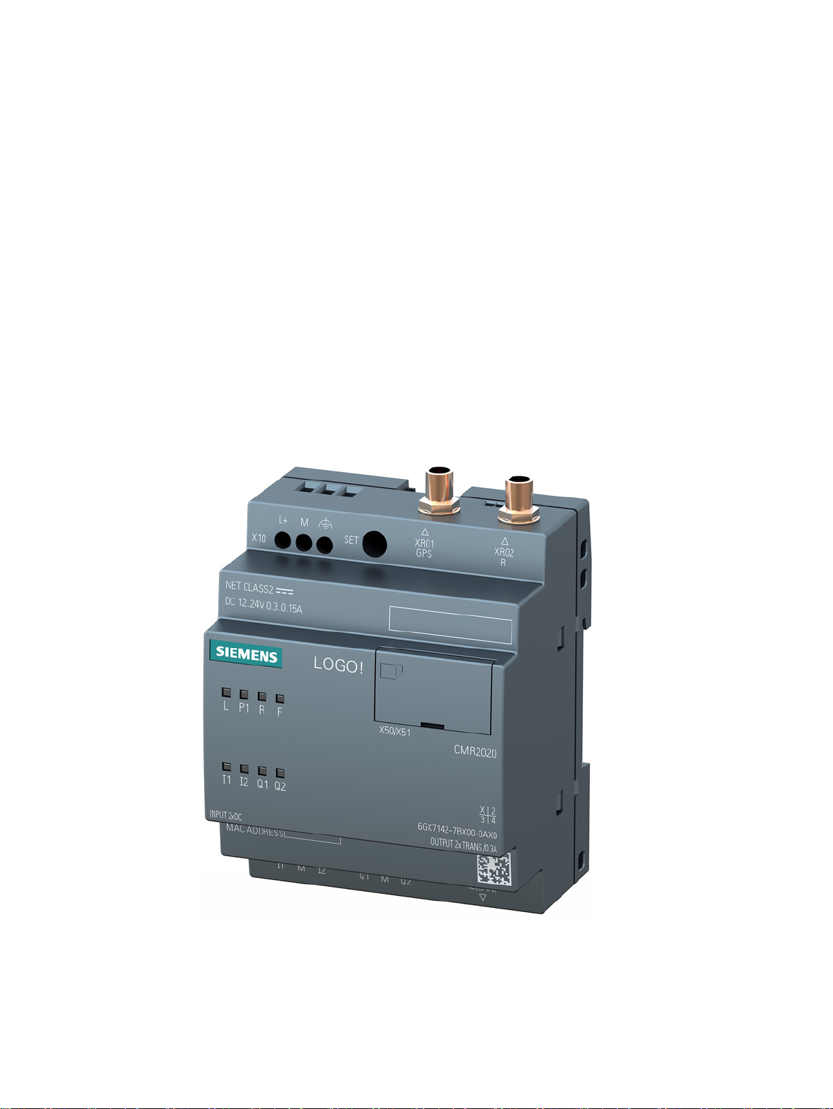
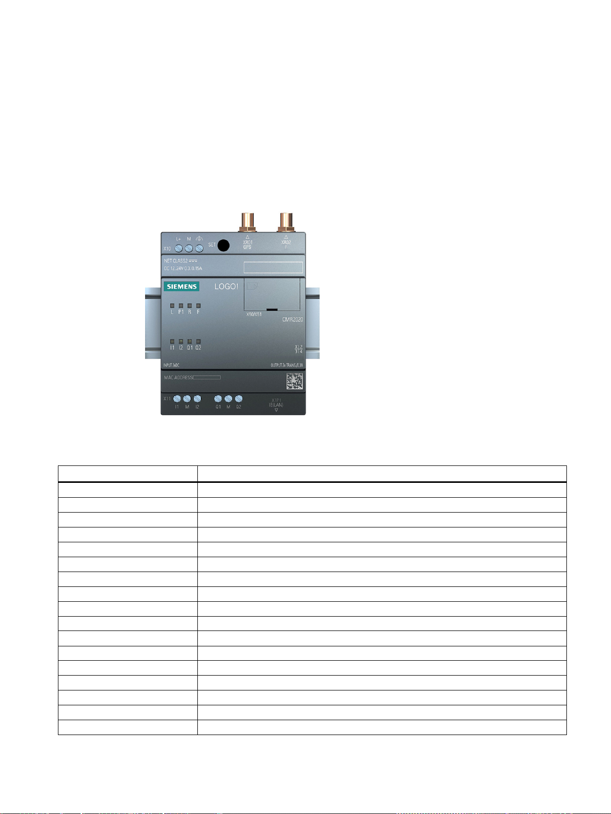
Figure 1 LOGO! CMR2020
LOGO! CMR2020 and LOGO! CMR2040 differ from each other only in the supported mobile
wireless standards GSM/GPRS (2G) and LTE (4G).
The range of functions of both wireless modules is identical.
3

Preface
Product names and abbreviations
Purpose of the manual
Current manual release on the Internet
● CMR or device
In this document, the term "CMR" or "device" is also used instead of the full product name
"LOGO! CMR2020 or LOGO! CMR2040. CMR is the abbreviation for Communication
Module Radio.
● BM or LOGO! BM
Basic module: LOGO! 8
● WBM
Web Based Management; Web user interface with which the CMR is configured.
● SD card/micro SD card
In this document, the term "CD card" is used instead of micro SD card.
This manual supports you during the configuration, installation, commissioning and operation
of the two LOGO! wireless modules LOGO! CMR2020 and LOGO! CMR2040:
LOGO! CMR2020
1. GSM/GPRS
2. GPS
LOGO! CMR2040
Europe/Australia:
1. 4G: LTE 800 (B20) / 1800 (B3) / 2600 (B7)
If the establishment of a mobile data connection to the LTE mobile wireless network fails,
there is a fallback to the next lower mobile wireless standards 2. and 3.
2. 3G: HSPA+ / UMTS 900 (B8) / 2100 (B1) / 1800 (B3)
3. 2G: QB GSM/GPRS/EDGE
4. GPS
A detailed example (Page 114) supports you during commissioning.
You will also find the current version of this manual on the Internet pages of Siemens
Industry Online Support under the following entry ID:
91689511 (http://support.automation.siemens.com/WW/view/en/91689511)
> Entry list > Entry type "Manuals"
LOGO! CMR2020 / LOGO! CMR2040
4 Operating Instructions, 09/2014, C79000-G8976-C356-01
Preface
Sources of information and other documentation
Purpose of the device
WARNING
Impairment of medical devices and data media
License conditions
Note
Open source software
Read
Security information
You will find an overview of further reading and references in the Documentation references
in this manual.
Connection of a LOGO! BM to an LTE, UMTS or GSM/GPRS mobile wireless network and a
GPS system.
The device contains a wireless transmitter that could, under certain circumstances, impair
the functionality of electronic medical devices such as hearing aids or pacemakers. Do not
use the device in places where the operation of wireless devices is prohibited. You can
obtain advice from your physician or the manufacturer of such devices.
To prevent data media from being demagnetized, do not keep disks, credit cards or other
magnetic data media near the device.
The license conditions for open source software are stored on the device and can be read
out using the WBM:
In the header of each page there is an icon with which you can download the OSS license
texts.
Siemens provides products and solutions with industrial security functions that support the
secure operation of plants, solutions, machines, equipment and/or networks. They are
important components in a holistic industrial security concept. With this in mind, Siemens’
products and solutions undergo continuous development. Siemens recommends strongly
that you regularly check for product updates.
For the secure operation of Siemens products and solutions, it is necessary to take suitable
preventive action (e.g. cell protection concept) and integrate each component into a holistic,
state-of-the-art industrial security concept. Third-party products that may be in use should
also be considered. For more information about industrial security, visit
http://www.siemens.com/industrialsecurity.
the license conditions for open source software carefully before using the product.
LOGO! CMR2020 / LOGO! CMR2040
Operating Instructions, 09/2014, C79000-G8976-C356-01
newsletter. For more information, visit http://support.automation.siemens.com.
To stay informed about product updates as they occur, sign up for a product-specific
5

Preface
Trademarks
SIMATIC NET glossary
Service & Support
The following and possibly other names not identified by the registered trademark sign ® are
registered trademarks of Siemens AG:
SIMATIC NET
Explanations of many of the specialist terms used in this documentation can be found in the
SIMATIC NET glossary.
You will find the SIMATIC NET glossary here:
● SIMATIC NET Manual Collection or product DVD
The DVD ships with certain SIMATIC NET products.
● On the Internet under the following entry ID:
50305045 (http://support.automation.siemens.com/WW/view/en/50305045)
In addition to the product documentation, the comprehensive online information platform of
Siemens Automation Customer Support supports at any time and at any location in the
world. You will find the Service & Support pages on the Internet at the following address:
(www.siemens.com/automation/service&support)
Apart from news, you will also find the following information there:
● Product information, Product Support, Applications & Tools
● Technical Forum
● Technical Support - Ask the Siemens experts
● Our service offer:
– Technical Consulting, Engineering support
– Field Service
– Spare parts and repairs
– Maintenance, optimization, modernization and more
You will find contact data on the Internet at the following address:
(www.automation.siemens.com/partner)
LOGO! CMR2020 / LOGO! CMR2040
6 Operating Instructions, 09/2014, C79000-G8976-C356-01

Preface
SITRAIN - Siemens training for automation and industrial solutions
With over 300 different courses, SITRAIN covers the entire Siemens product and system
spectrum in the field of automation and drive technology. Apart from the classic range of
courses, we also offer training tailored for individual needs and a combination of different
teaching media and sequences, for example self-learning programs on CD-ROM or on the
Internet.
You will find detailed information on the training curriculum and how to contact our customer
consultants at the following Internet address:
(www.siemens.com/sitrain)
LOGO! CMR2020 / LOGO! CMR2040
Operating Instructions, 09/2014, C79000-G8976-C356-01
7

Preface
LOGO! CMR2020 / LOGO! CMR2040
8 Operating Instructions, 09/2014, C79000-G8976-C356-01

Table of contents
Preface ................................................................................................................................................... 3
1 Properties and functions........................................................................................................................ 13
2 Connectors and LED display ................................................................................................................. 17
3 Requirements for use ............................................................................................................................ 23
4 Installation, connecting up, commissioning ............................................................................................ 25
5 Application examples ............................................................................................................................ 37
6 Configuration ........................................................................................................................................ 47
1.1 Connection using mobile wireless, Internet and GPS ............................................................ 13
1.2 Configuration and functions .................................................................................................... 14
2.1 Appearance of the device ....................................................................................................... 17
2.2 Interfaces ................................................................................................................................ 18
2.3 LEDs to display operation ....................................................................................................... 19
4.1 Power supply .......................................................................................................................... 26
4.2 X1P1 (LAN) interface .............................................................................................................. 28
4.3 SMA antenna sockets ............................................................................................................. 29
4.4 Frequency bands and signal strength ..................................................................................... 29
4.5 Mounting ................................................................................................................................. 30
4.6 Steps in commissioning .......................................................................................................... 32
4.7 Insert the SIM card and enter the PIN .................................................................................... 33
4.8 Inserting the micro SD card .................................................................................................... 35
4.9 Connecting up the inputs and outputs .................................................................................... 36
5.1 Mobile wireless communication without LOGO! BM ............................................................... 38
5.2 Mobile wireless communication with LOGO! BM .................................................................... 39
5.3 Position detection (GPS) ........................................................................................................ 41
5.4 Time-of-day synchronization ................................................................................................... 43
6.1 Permitted characters and character lengths ........................................................................... 47
6.2 Establishing a connection to the CMR .................................................................................... 49
6.2.1 Establishing the configuration connection .............................................................................. 49
6.2.2 Basics of configuration ............................................................................................................ 51
6.2.3 Language selection ................................................................................................................. 53
6.3 Start page ............................................................................................................................... 54
6.4 System .................................................................................................................................... 55
LOGO! CMR2020 / LOGO! CMR2040
Operating Instructions, 09/2014, C79000-G8976-C356-01
9

Table of contents
7 Operation .............................................................................................................................................. 85
6.4.1 Calling the Web page ............................................................................................................. 55
6.4.2 General .................................................................................................................................. 56
6.4.3 Hardware information ............................................................................................................. 57
6.4.4 System time ........................................................................................................................... 58
6.5 Diagnostics ............................................................................................................................. 62
6.5.1 Calling the Web page ............................................................................................................. 62
6.5.2 Diagnostics buffer .................................................................................................................. 62
6.5.3 SMS notifications ................................................................................................................... 64
6.6 Maintenance ........................................................................................................................... 65
6.6.1 Calling the Web page ............................................................................................................. 65
6.6.2 Configuration .......................................................................................................................... 65
6.6.3 Firmware ................................................................................................................................ 67
6.6.4 System ................................................................................................................................... 69
6.6.4.1 Shut down to safe status ........................................................................................................ 69
6.6.4.2 Run restart ............................................................................................................................. 69
6.6.4.3 Reset to factory settings ........................................................................................................ 70
6.6.5 Online Support ....................................................................................................................... 72
6.7 LAN ........................................................................................................................................ 74
6.7.1 Calling the Web page ............................................................................................................. 74
6.7.2 Configuration .......................................................................................................................... 75
6.8 WAN ....................................................................................................................................... 76
6.8.1 Calling the Web page ............................................................................................................. 76
6.8.2 Overview ................................................................................................................................ 76
6.8.3 Mobile wireless settings ......................................................................................................... 77
6.8.3.1 Activate mobile wireless interface .......................................................................................... 78
6.8.3.2 PIN of the SIM card ................................................................................................................ 79
6.8.3.3 Allow roaming ......................................................................................................................... 80
6.8.3.4 Phone number of the SMS service center ............................................................................. 80
6.8.3.5 Activating a data connection via the mobile wireless network ............................................... 80
6.8.3.6 APN / User name / Password ................................................................................................ 81
6.8.4 Wireless cell ........................................................................................................................... 82
6.8.5 SMS ....................................................................................................................................... 83
7.1 Users / groups ........................................................................................................................ 88
7.1.1 Calling the Web page ............................................................................................................. 89
7.1.2 Users ...................................................................................................................................... 89
7.1.3 Recipient groups .................................................................................................................... 92
7.2 Monitoring .............................................................................................................................. 94
7.2.1 Calling the Web page ............................................................................................................. 94
7.2.2 Which task needs to be completed? - Which steps are necessary for this? ......................... 95
7.2.3 Principle of monitoring and message configuration ............................................................... 96
7.2.4 Overview ................................................................................................................................ 98
7.2.5 LOGO! BM ........................................................................................................................... 100
7.2.6 Message texts ...................................................................................................................... 101
7.2.7 Signal definitions .................................................................................................................. 103
7.2.8 Events .................................................................................................................................. 105
7.2.9 Actions ................................................................................................................................. 107
7.2.9.1 Forwarding GPS position data to LOGO! BM ...................................................................... 109
7.2.10 Assignments ......................................................................................................................... 111
LOGO! CMR2020 / LOGO! CMR2040
10 Operating Instructions, 09/2014, C79000-G8976-C356-01

Table of contents
8 Dimension drawings ............................................................................................................................ 135
9 Accessories ........................................................................................................................................ 137
10 Technical specifications ...................................................................................................................... 143
11 Approvals ............................................................................................................................................ 147
A Documentation references .................................................................................................................. 151
Index................................................................................................................................................... 153
7.2.11 Example of a monitoring configuration ................................................................................. 114
7.3 SMS message structures and examples .............................................................................. 119
7.3.1 Response of the CMR when receiving an SMS message/replying to SMS message ......... 119
7.3.2 SMS error messages ............................................................................................................ 121
7.3.3 Syntax of all SMS commands ............................................................................................... 122
7.3.4 SMS commands .................................................................................................................... 122
7.3.5 Reply SMS message to the "MONITOR?" command ........................................................... 127
7.3.6 Diagnostics SMS message ................................................................................................... 131
7.4 Disruptions and their possible causes .................................................................................. 132
9.1 Antenna and cabling technology for LOGO! CMR ................................................................ 137
11.1 National approvals GSM, UMTS and LTE ............................................................................ 147
LOGO! CMR2020 / LOGO! CMR2040
Operating Instructions, 09/2014, C79000-G8976-C356-01
11

Table of contents
LOGO! CMR2020 / LOGO! CMR2040
12 Operating Instructions, 09/2014, C79000-G8976-C356-01
1
1.1
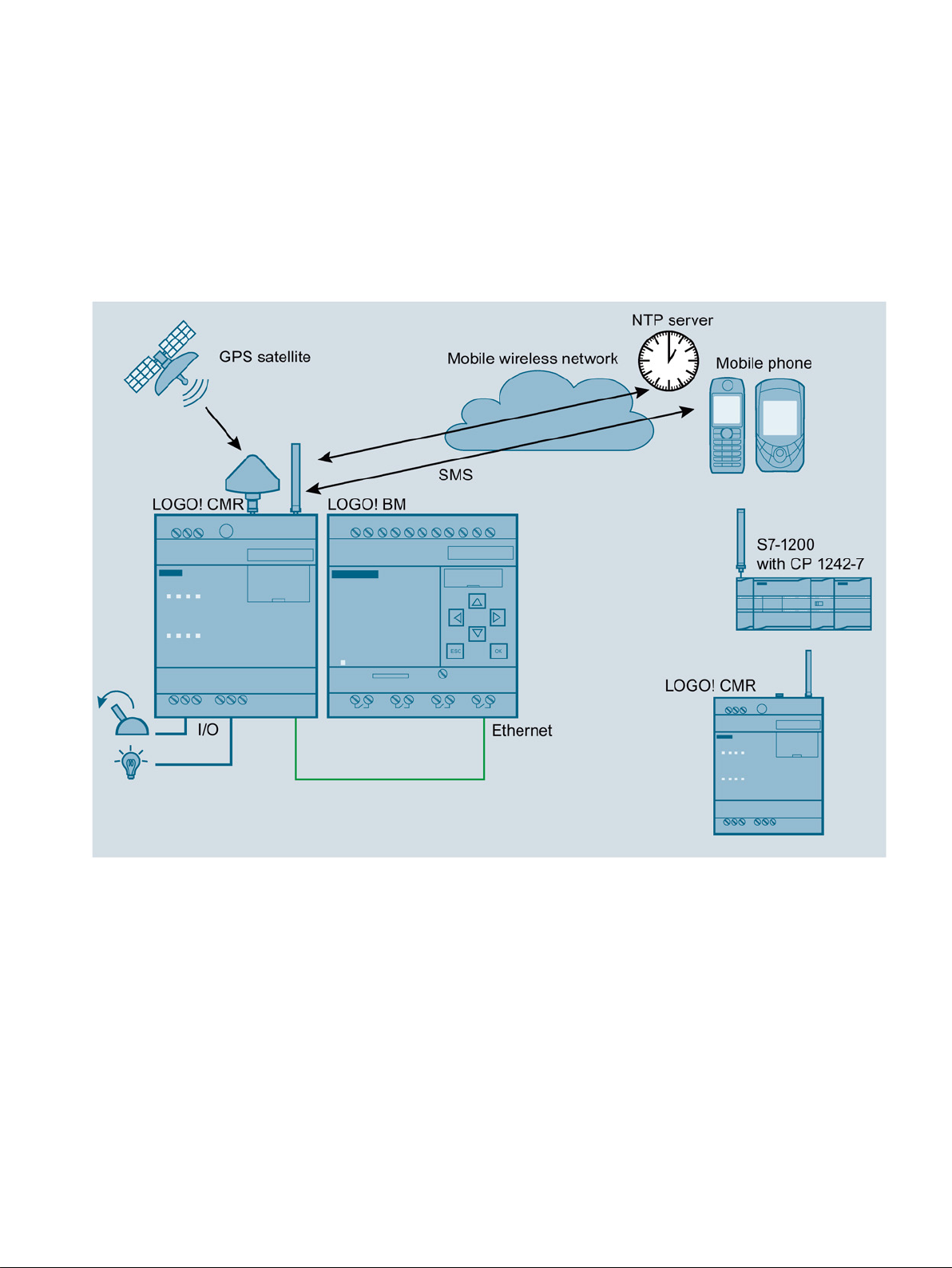
Connection using mobile wireless, Internet and GPS
Wireless connection via the mobile wireless network
With the CMR, you establish a mobile data connection to a mobile wireless network: LTE,
UMTS or GSM/GPRS mobile wireless network. You are also in a position to connect the
CMR to a GPS system.
With the CMR, you can do the following:
● Read the information of a BM using SMS: Process image, inputs/outputs, memory bits
and much more
● Notify event-based using SMS.
The CMR is connected locally to a BM via Ethernet and establishes the connection to a
mobile wireless network.
LOGO! CMR2020 / LOGO! CMR2040
Operating Instructions, 09/2014, C79000-G8976-C356-01
13

Properties and functions
Requirements for operation
1.2
Configuration and functions
Configuring the CMR
1.2 Configuration and functions
You can also operate the CMR in stand-alone mode: in other words without a connected BM.
To connect the I/O you use the two inputs and outputs of the CMR.
Mobile wireless network within reach
● To be able to send and receive SMS messages, there must be a reachable mobile
wireless network.
Sending SMS messages
● You require a SIM card from a mobile wireless provider. The SIM card must be activated
for sending SMS messages. This SIM card must have a telephone number.
Time-of-day synchronization with NTP
● You require a SIM card with mobile data options: This SIM card does not need to have a
telephone number.
● You require a mobile wireless network within reach that supports the exchange of mobile
data.
You configure the CMR locally using a Web user interface (WBM) that can be displayed with
a Web browser:
1. Connect a PC to the "X1P1 IE (LAN)" connector of the CMR. To do this, use an Ethernet
2. Start the Web user interface as described in the section Configuration (Page 47).
patch cable.
LOGO! CMR2020 / LOGO! CMR2040
14 Operating Instructions, 09/2014, C79000-G8976-C356-01

Properties and functions
Functions
1.2 Configuration and functions
The CMR supports the following basic functions:
1. Web user interface (WBM) for the configuration; protected with login and password query.
2. Cyclic reading of the process image from the BM.
3. From incoming events, events coming from the process or internal, suitable output
reactions configured using WBM are generated: For example sending an alarm SMS
message.
4. Event configurations and reactions, for example trigger an alarm SMS message if a value
changes in the process image.
The process image consists of the following elements that you can use for an event or
alarm configuration:
– Digital and analog inputs
– Digital and analog outputs
– Digital and analog bit memory
– Shift register
– Operator keys
– Function keys
5. Access to variable memory (VM)
Via the variables memory, you have access to the current values of function blocks, for
example counter function blocks.
6. Time-of-day synchronization
– NTP
– GPS
– Mobile wireless network (depending on the mobile wireless provider)
7. Forwarding the time of day to the BM
8. GPS position
– Querying position by SMS
– Forwarding position to the BM
9. The two inputs/outputs of the CMR can be configured using the WBM and read or set
using SMS messages.
10.Access protection when receiving SMS messages: Only SMS messages from configured
telephone numbers are permitted.
LOGO! CMR2020 / LOGO! CMR2040
Operating Instructions, 09/2014, C79000-G8976-C356-01
15

Properties and functions
Diagnostics via the local area network
1.2 Configuration and functions
Using WBM you can view a diagnostics buffer for diagnostics purposes. Is also possible to
download and save the diagnostics buffer on an SD card or PC.
The following are logged, for example:
● Operating messages such as startup, change to the configuration.
● Establishment/interruption of the connection to the BM.
● Establishment/interruption of the connection to the mobile wireless network.
● Establishment/interruption of the mobile data connection.
● Warnings when reading in the configuration from an SD card or from the PC.
● Time-of-day synchronization
LOGO! CMR2020 / LOGO! CMR2040
16 Operating Instructions, 09/2014, C79000-G8976-C356-01
2
2.1
Appearance of the device
Operator control/connector and display elements of the CMR
Element
Function
X10 (L+, M)
Power supply connector
SET
Service button SET, refer to the section "Functions of the SET button"
XR01
GPS antenna connector
XR02
Mobile wireless antenna connector
LED "L"
Power supply indicator
LED "P1"
LAN interface indicator
LED "R"
Mobile wireless signal strength indicator
LED "F"
Error/fault indicator
X50/X51
Slot for SIM and micro SD card
LED I1
Input 1 indicator
LED Q1
Output 1 indicator
LED Q2
Output 2 indicator
I1
Input 1 connector
M
Ground
I2
Input 2 connector
Q1
Output 1 connector
LED I2 Input 2 indicator
LOGO! CMR2020 / LOGO! CMR2040
Operating Instructions, 09/2014, C79000-G8976-C356-01
17
Connectors and LED display
Element
Function
M
Ground
Q2
Output 2 connector
X1P1
LAN connector
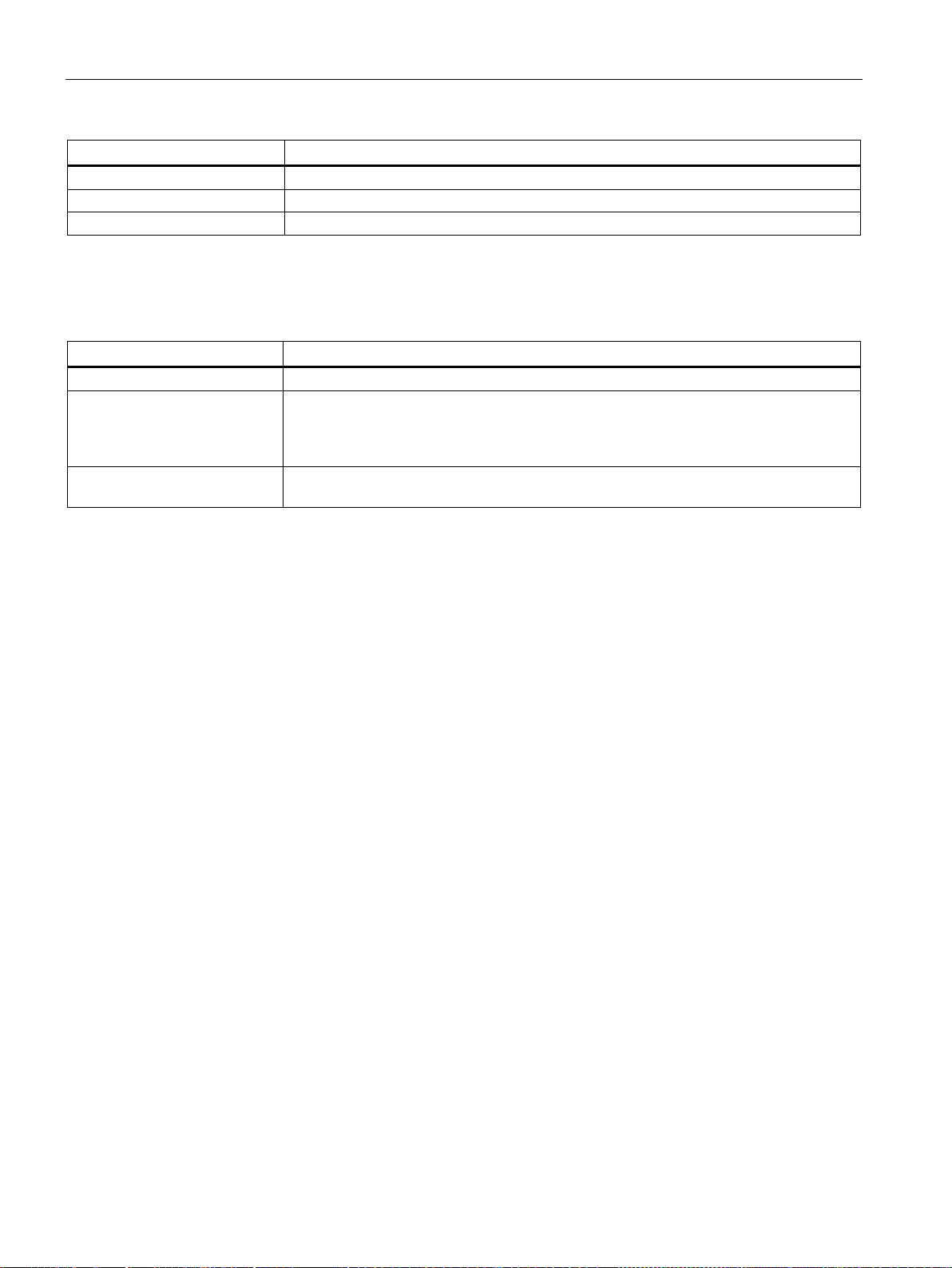
Functions of the SET button
Operator input
Function
Keep pressed for 5 s
Restart
10 seconds
2.2
Interfaces
Connection to a the local area network
Connection to the mobile wireless network and GPS
2.2 Interfaces
The SET button has different functions depending on how long you press it.
Keep pressed for 5 to 10 seconds
Keep pressed for longer than
Shutting down the device to a safe status:
• No LEDs are lit.
• The device can be disconnected from the power supply.
Reset to factory settings
Port X1P1 of the CMR is intended for LAN connection to the local network/PC and to
connect to the BM. The IP address of port X1P1 can be configured.
For the wireless connection, the CMR has two SMA sockets:
● SMA socket for the mobile wireless network
● SMA socket for GPS reception
LOGO! CMR2020 / LOGO! CMR2040
18 Operating Instructions, 09/2014, C79000-G8976-C356-01

Connectors and LED display
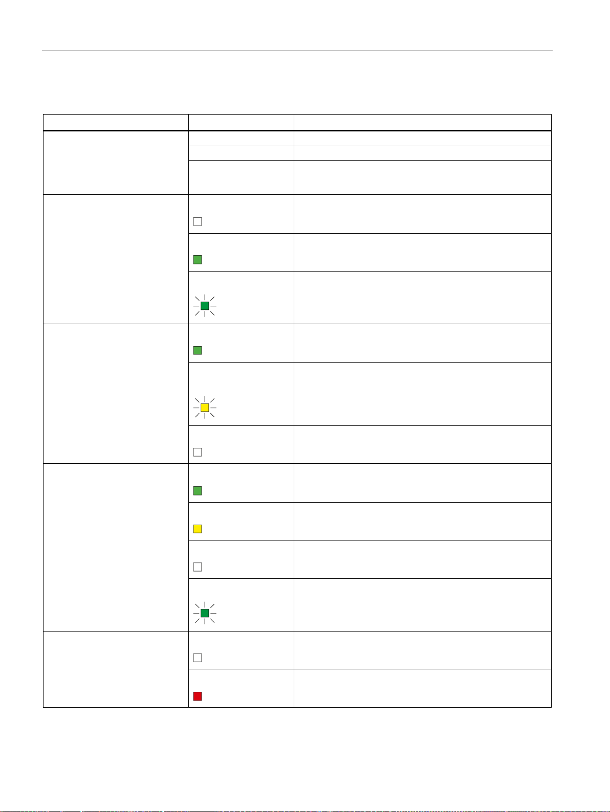
2.3
LEDs to display operation
2.3 LEDs to display operation
The LEDs on the CMR provide information about the operating status of the device and the
two inputs/outputs.
LOGO! CMR2020 / LOGO! CMR2040
Operating Instructions, 09/2014, C79000-G8976-C356-01
19
Connectors and LED display
Meaning of the LEDs
LED
Status
Meaning
Flashing
Fatal error
Lit
Firmware being updated
2.3 LEDs to display operation
All LEDs
L
Power supply
P1
LAN
Not lit
Off
On
Flashing
Lit green
Part flashes yellow and
part lit green
Off
• No voltage present or applied
• Device shut down
No external power supply connected
Power supply connected
Initialization or reconfiguration active
Link
Data
No link or no cable connected
R
Signal strength (mobile wireless)
F
Error
LOGO! CMR2020 / LOGO! CMR2040
Lit green
Lit yellow
Off
Flashing
OFF
ON
Very good
Medium
No signal
Data
No error
Error (see also "Error LED lights up red" (Page 132))
20 Operating Instructions, 09/2014, C79000-G8976-C356-01
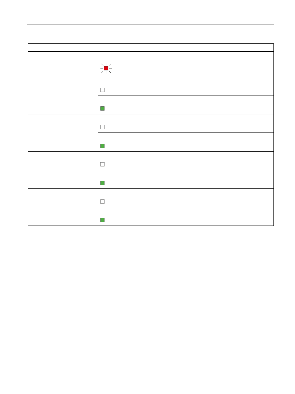
Connectors and LED display
LED
Status
Meaning
2.3 LEDs to display operation
I1
Input 1
I2
Input 2
Q1
Output 1
Q2
Output 2
Flashing
Off
Lit green
Off
Lit green
Off
Lit green
Off
Duplicate IP address detected. Ethernet interface unreachable.
U < 5 V
U > 8.5 V
U < 5 V
U > 8.5 V
No voltage at output
Supply voltage at output
No voltage at output
Lit green
Supply voltage at output
LOGO! CMR2020 / LOGO! CMR2040
Operating Instructions, 09/2014, C79000-G8976-C356-01
21

Connectors and LED display
2.3 LEDs to display operation
LOGO! CMR2020 / LOGO! CMR2040
22 Operating Instructions, 09/2014, C79000-G8976-C356-01

3
Antennas
Power supply
To operate the CMR, you require an antenna that is tuned to the frequency bands of the
mobile wireless provider you have selected.
● For GSM/GPRS transmission (LOGO! CMR2020):
– 850 MHz, 900 MHz, 1800 MHz or 1900 MHz; quad-band
● For LTE transmission (LOGO! CMR2040 only):
– 4G: 800 MHz (B20), 1800 MHz (B3), 2600 MHz (B7)
– Fallback* to 3G (UMTS, HSUPA and HSDPA): 900 MHz (B8), 2100 MHz (B1)
– Fallback* to 2G (GSM/GPRS): 850 MHz, 900 MHz, 1800 MHz or 1900 MHz
* Fallback to the next lower standard (LTE > UMTS > GSM/GPRS and EDGE)
If you want to use GPS, you require an additional GPS antenna:
● Only use antennas from the accessories program for the CMR. For more information,
refer to the section Antenna and cabling technology for LOGO! CMR (Page 137).
You require a power supply with a voltage between 12 VDC and 24 VDC that provides
adequate voltage or current. For more information, refer to the section Technical
specifications (Page 143).
LOGO! CMR2020 / LOGO! CMR2040
Operating Instructions, 09/2014, C79000-G8976-C356-01
23

Requirements for use
SIM card
You require a SIM card of your mobile wireless provider with the corresponding PIN
(Personal Identification Number).
Exception: SIM cards that are only used for the data service can be used without a PIN.
Only necessary if NTP is used:
● Activation for packet-oriented data services
The SIM card must be activated for the packet-oriented data services in the mobile
wireless network by your mobile wireless provider:
– LOGO! CMR2020: GPRS
– LOGO! CMR2040: LTE
As the preferred connection, LOGO! CMR2040 first attempts to establish a connection
to the LTE mobile wireless network.
If the connection to the LTE mobile wireless network fails, the CMR attempts to
establish a connection to the UMTS mobile wireless network.
If the connection to the UMTS mobile wireless network fails, the CMR attempts to
establish a connection to the GSM/GPRS mobile wireless network.
– The following access data for the mobile wireless network must be present: Access
Point Name (APN), user name and password.
For more information, refer to the section Mobile wireless settings (Page 77).
LOGO! CMR2020 / LOGO! CMR2040
24 Operating Instructions, 09/2014, C79000-G8976-C356-01
4
Safety notices on the use of the device
WARNING
Safety extra low voltage
There is an additional requirement if devices are operated with a redundant power supply:
External power supply
NOTICE
Power supply
The following safety notices must be adhered to when setting up and operating the device
and during all associated work such as installation, connecting up or replacing devices.
The equipment is designed for operation with Safety Extra-Low Voltage (SELV) by a
Limited Power Source (LPS). (This does not apply to 100 V...240 V devices.)
This means that only SELV / LPS complying with IEC 60950-1 / EN 60950-1 / VDE 0805-1
must be connected to the power supply terminals. The power supply unit for the equipment
power supply must comply with NEC Class 2, as described by the National Electrical Code
(r) (ANSI / NFPA 70).
If the equipment is connected to a redundant power supply (two separate power supplies),
both must meet these requirements.
● Use only an external power supply that complies with EN 60950.
● The output voltage of the external power supply must not exceed 30 VDC.
● The output of the external power supply must be short-circuit proof.
The power supply unit to supply the CMR must comply with the requirements for a limited
power source according to IEC/EN 60950-1, section 2.5.
The external power supply for the CMR must meet the requirements for NEC class 2
circuits as specified in the National Electrical Code ® (ANSI/NFPA 70).
Note the information in this section and in the installation and operating instructions from the
manufacturer of the power supply.
LOGO! CMR2020 / LOGO! CMR2040
Operating Instructions, 09/2014, C79000-G8976-C356-01
25
Installation, connecting up, commissioning
Overvoltage protection
NOTICE
Protection of the external power supply
4.1
Power supply
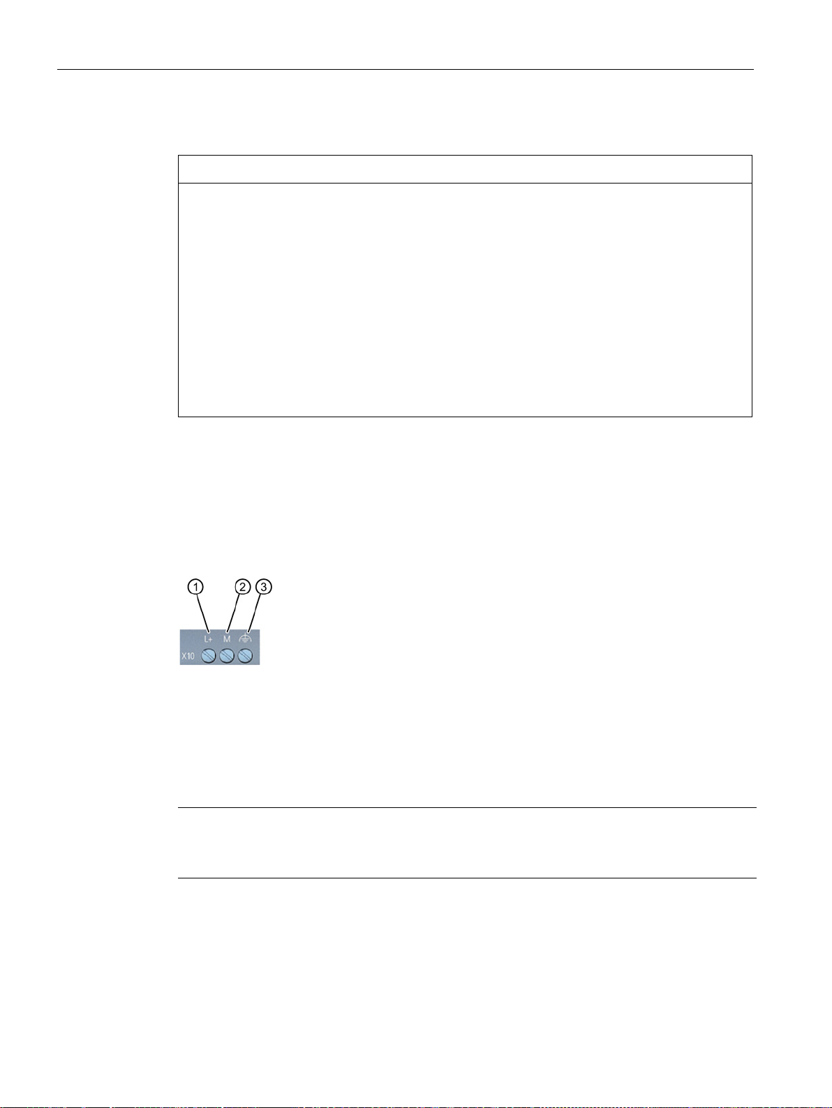
Screw terminals for the power supply
①
L+ = live wire, positive pole of the DC voltage 12/24 VDC
②
M = negative pole/ground of the DC voltage 12/24 VDC
③
Note
Power supply unit of the CMR is not electrically isolated
No electrical isolation means that the input and output circuits are not galvanically is
4.1 Power supply
If power is supplied to the module or station over longer power cables or networks, the
coupling in of strong electromagnetic pulses onto the power supply cables is possible. This
can be caused, for example by lightning strikes or switching of higher loads.
The connector of the external power supply is not protected from strong electromagnetic
pulses. To protect it, an external overvoltage protection module is necessary. The
requirements of EN 61000-4-5, surge immunity tests on power supply lines, are met only
when a suitable protective element is used. A suitable device is, for example, the Dehn
Blitzductor BVT AVD 24, article number 918 422 or a comparable protective element.
Manufacturer:
DEHN+SOEHNE GmbH+Co.KG Hans Dehn Str.1 Postfach 1640 D-92306 Neumarkt,
Germany
Functional ground
• Serves to improve electromagnetic compatibility and to specify a common reference poten-
tial for all signals.
• Is achieved efficiently by a connection to the DIN rail.
olated.
LOGO! CMR2020 / LOGO! CMR2040
26 Operating Instructions, 09/2014, C79000-G8976-C356-01

Installation, connecting up, commissioning
Wire:
0,5 ... 3 mm² (20 to 18 AWG)
Stranded wire:
0,5 ... 2.5 mm²
Tightening torque for screw terminals:
0,6 ... 0.8 Nm
Turning off the CMR
NOTICE
Avoidance of sudden disconnection of the power supply
4.1 Power supply
The CMR operates with a DC voltage of 12 to 24 VDC, nominally 24 VDC. The nominal
current consumption is a maximum of 250 mA at 12 V.
● Connect a suitable power supply to the screw terminals.
● Use copper wires only.
Avoid abrupt, uncontrolled disconnection of the CMR from the power supply: There is a risk
of damaging the CMR!
1. Hold down the SET button for 5 to 10 seconds.
2. Disconnect the CMR from the power supply.
The CMR can no longer be woken out of the shutdown status. Power cycling necessary.
The CMR shuts down to the safe status: All LED indicators are off.
LOGO! CMR2020 / LOGO! CMR2040
Operating Instructions, 09/2014, C79000-G8976-C356-01
27
Installation, connecting up, commissioning
4.2
X1P1 (LAN) interface
Connecting the X1P1 (LAN) interface
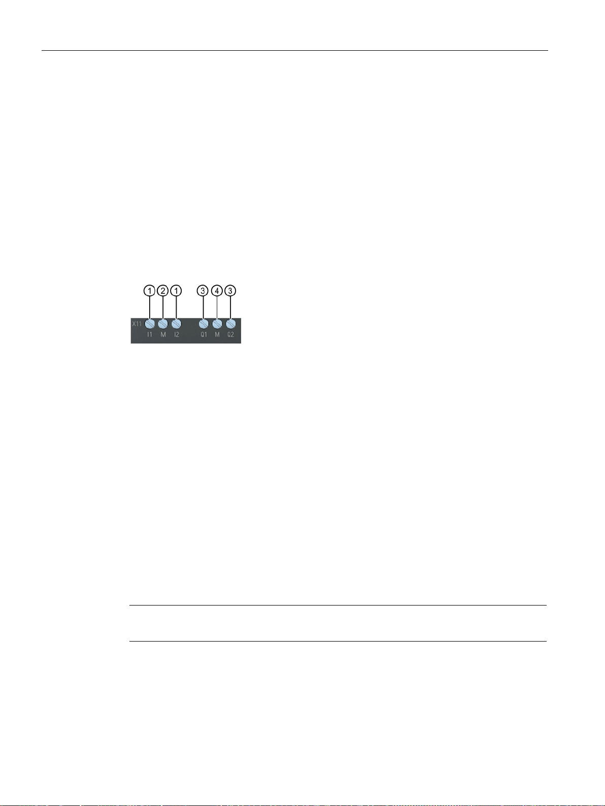
Inputs and outputs
①
Inputs I1 and I2
②
Reference potential inputs
③
Outputs Q1 and Q2
④
Reference potential outputs
Inputs I1 and I2
Outputs Q1 and Q2
Note
Remember the electrica
4.2 X1P1 (LAN) interface
The interface supports autonegotiation and autocrossing. For the connection, use a patch
cable with an RJ-45 plug. You will find the properties of the X1P1 interface in the technical
specifications.
● Connect your local area network, the PC or the BM to X1P1 (LAN) of the CMR.
The CMR has two inputs and two outputs. The connecting terminals are on the underside of
the device.
The connecting terminals of the inputs are labeled I1 and I2. The reference potential for both
inputs is "M".
Using the Web user interface, you can assign any function to each input, for example
triggering an alarm SMS message (Page 94).
The status of an input can also be read using SMS.
The connecting terminals of the outputs are labeled Q1 and Q2. The reference potential for
both outputs is "M".
You can assign any function (Page 94) to each output using the Web user interface. The
outputs can be set and reset using SMS messages.
l load capacity of the output.
LOGO! CMR2020 / LOGO! CMR2040
28 Operating Instructions, 09/2014, C79000-G8976-C356-01
You will find the electrical values for the inputs and outputs in the section Technical
specifications (Page 143).
Installation, connecting up, commissioning
4.3
SMA antenna sockets
WARNING
Risk of lightning strikes when installed outdoors
NOTICE
Damage to devices due to incorrect accessories
4.4
Frequency bands and signal strength
Frequency bands in Europe and other regions
Signal strength
4.3 SMA antenna sockets
If you install an antenna outside, you need to ground the antenna to protect it from lightning
strikes. This work must only be carried out by qualified personnel.
Select the antenna suitable for your frequency band from the accessories. Other antennas
could interfere with product characteristics or lead to defects.
The CMR has two antenna sockets of the type SMA for connecting the antennas. The
antennas must have an impedance of approx. 50 Ω.
Follow the operating instructions of the antennas used. See also section Antenna and
cabling technology for LOGO! CMR (Page 137).
Depending on the frequency bands your mobile wireless provider uses:
● Select the antenna suitable for your frequency band from the accessories (Page 137).
During installation make sure that there is a good signal strength:
● If the "R" LED is lit green or flashes green, the signal strength is very good.
● Lit yellow or flashing yellow signals medium quality.
● If the "R" LED is not lit, this indicates an inadequate signal strength, refer also to the
section LEDs to display operation (Page 19).
Large metallic objects in the vicinity of the antennas, for example reinforced concrete, impair
the signal strength.
LOGO! CMR2020 / LOGO! CMR2040
Operating Instructions, 09/2014, C79000-G8976-C356-01
29
Installation, connecting up, commissioning
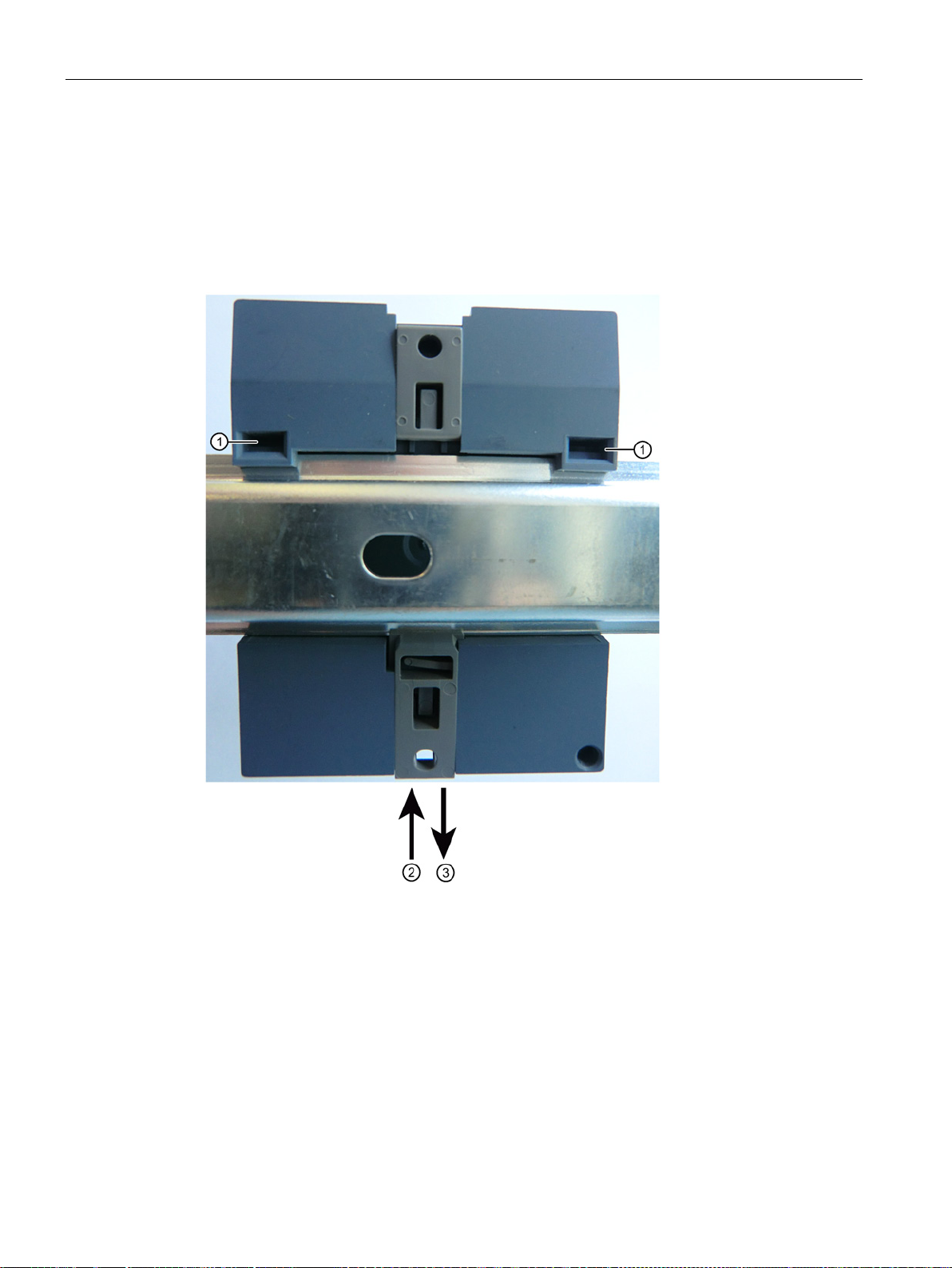
4.5
Mounting
Installing on a DIN rail / removing from a DIN rail
4.5 Mounting
The CMR is suitable for rail mounting on a 35 mm DIN EN 50 022 rail. On the rear of the
device there is a locking mechanism with a spring catch.
Figure 4-1 Installing on a DIN rail / removing from a DIN rail
LOGO! CMR2020 / LOGO! CMR2040
30 Operating Instructions, 09/2014, C79000-G8976-C356-01
 Loading...