

Siemens SIMATIC IPC677D, SIMATIC IPC427D, SIMATIC IPC827D, SIMATIC IPC847D, SIMATIC IPC477D Operating Manual
...
BIOS Description
___________________
___________________
___________________
___________________
___________________
___________________
SIMATIC
Industrial PC
BIOS Description
Operating Manual
05/2016
A5E33664825
-AB
Preface
Overview
1
Opening the BIOS selection
menu
2
BIOS Setup (SCU)
3
AMT Setup (MEBx)
4
BIOS update
5
Siemens AG
Division Digital Factory
Postfach 48 48
90026 NÜRNBERG
GERMANY
A5E33664825-AB
Ⓟ
05/2016 Subject to change
Copyright © Siemens AG 2016.
All rights reserved
Legal information
Warning notice system
This manual contains notices you have to observe in order to ensure your personal safety, as well as to prevent
damage to property. The notices referring to your personal safety are highlighted in the manual by a safety alert
symbol, notices referring only to property damage have no safety alert symbol. These notices shown below are
graded according to the degree of danger.
DANGER
indicates that death or severe personal injury will result if proper precautions are not taken.
WARNING
indicates that death or severe personal injury may result if proper precautions are not taken.
CAUTION
indicates that minor personal injury can result if proper precautions are not taken.
NOTICE
indicates that property damage can result if proper precautions are not taken.
If more than one degree of danger is present, the warning notice representing the highest degree of danger will
be used. A notice warning of injury to persons with a safety alert symbol may also include a warning relating to
property damage.
Qualified Personnel
The product/system described in this documentation may be operated only by
personnel qualified
for the specific
task in accordance with the relevant documentation, in particular its warning notices and safety instructions.
Qualified personnel are those who, based on their training and experience, are capable of identifying risks and
avoiding potential hazards when working with these products/systems.
Proper use of Siemens products
Note the following:
WARNING
Siemens products may only be used for the applications described in the catalog and in the relevant technical
documentation. If products and components from other manufacturers are used, these must be recommended
or approved by Siemens. Proper transport, storage, installation, assembly, commissioning, operation and
maintenance are required to ensure that the products operate safely and without any problems. The permissible
ambient conditions must be complied with. The information in the relevant documentation must be observed.
Trademarks
All names identified by ® are registered trademarks of Siemens AG. The remaining trademarks in this publication
may be trademarks whose use by third parties for their own purposes could violate the rights of the owner.
Disclaimer of Liability
We have reviewed the contents of this publication to ensure consistency with the hardware and software
described. Since variance cannot be precluded entirely, we cannot guarantee full consistency. However, the
information in this publication is reviewed regularly and any necessary corrections are included in subsequent
editions.

BIOS Description
Operating Manual, 05/2016, A5E33664825-AB
3
Preface
This Operating Manual contains all the information you need to use the BIOS in your
SIMATIC IPC and SIMATIC Field programming device.
It is intended both for programming and testing personnel who commission the device and
connect it with an automation system, as well as for service and maintenance personnel who
install add-ons or carry out fault/error analyses.
Basic knowledge required
A solid background in personal computers and Microsoft operating systems is required to
understand this manual. General knowledge in the field automation control engineering is
recommended.
Conventions
The following abbreviations of product labels are used in this Operating Manual:
Generic term
Product label
IPC6x7
SIMATIC IPC627D, IPC677D, IPC647D
IPC8x7
SIMATIC IPC827D, IPC847D
IPC4x7 SIMATIC IPC427D, IPC477D
IPC2x7
SIMATIC IPC227D, IPC277D, IPC227E, IPC277E
Field programming device
Field PG M4, Field PG M5
Rack PC
SIMATIC IPC647D, IPC847D
Box PC
SIMATIC IPC627D, IPC827D, IPC427D, IPC227D, IPC277E
Panel PC
SIMATIC IPC677D, IPC477D, IPC277D, IPC277E
In this Operating Manual the abbreviation "PC" or the term "device" are used instead of the
product label.

Preface
BIOS Description
4 Operating Manual, 05/2016, A5E33664825-AB
Scope and history
The following editions of the Operating Manual have been released:
Version
Comments
02/2014 First edition created with the following BIOS versions:
• Rack PC: V19.01.01
• Box PC: V19.02.01 and V19.02.02
• Panel PC: V19.02.01 and V19.02.02
05/2016 Second edition, created with the following BIOS versions:
• Rack PC: V19.01.06
• Panel PC: V19.02.05
• Box PC: V19.02.05
• Field PG M5: V22.01.01
Note
Information on the BIOS version
The "Main" menu contains information on the BIOS version of your device.
See also
BIOS Setup settings (Page 40)

BIOS Description
Operating Manual, 05/2016, A5E33664825-AB
5
Table of contents
Preface ................................................................................................................................................... 3
1 Overview................................................................................................................................................. 7
2 Opening the BIOS selection menu .......................................................................................................... 9
3 BIOS Setup (SCU) ................................................................................................................................ 11
3.1 Starting BIOS Setup ................................................................................................................ 11
3.2 Structure of the BIOS Setup menu ......................................................................................... 11
3.3 Main menu .............................................................................................................................. 13
3.4 Advanced menu ...................................................................................................................... 14
3.5 Security menu ......................................................................................................................... 29
3.6 Power menu ............................................................................................................................ 31
3.7 Boot Menu ............................................................................................................................... 35
3.8 Exit menu ................................................................................................................................ 39
3.9 BIOS Setup settings ................................................................................................................ 40
4 AMT Setup (MEBx) ............................................................................................................................... 49
4.1 Login and Configuration .......................................................................................................... 49
5 BIOS update ......................................................................................................................................... 51
Index..................................................................................................................................................... 53

Table of contents
BIOS Description
6 Operating Manual, 05/2016, A5E33664825-AB

BIOS Description
Operating Manual, 05/2016, A5E33664825-AB
7
1
Parameterize your device in the BIOS Setup.
BIOS Setup program
The BIOS Setup program, or BIOS Setup for short, is located, together with the setup
parameters, in a FLASH block on the motherboard.
Change the setup parameters of the device in the BIOS Setup, e.g. system time or boot
sequence.
Changing the device configuration
Your device configuration is preset for operating with the included software. You should only
change the default setup parameters if technical modifications to your device require
different parameters.
NOTICE
Malfunctions can occur with running software CPU
If a BIOS update of the PC is performed while SIMATIC software controller, a SIMATIC
WinAC for example, is running, the software CPU can malfunction, resulting in
communication interruptions or failures, for example. Other actions that put a heavy load on
the PC hardware, for example, running hardware tests such as benchmarks, can result in
malfunctions of the software CPU.
Do not run a BIOS update or other actions that would put a heavy load on the hardware
during operation of a software CPU.
Switch the software CPU to "STOP" before you run a BIOS update or perform other critical
actions.
Note
Documentation
BIOS Setup is described for
all devices and device configurations. Some BIOS submenus or
Setup parameters may not be included, depending on your order. The interface of your BIOS
Setup can deviate from the figures in this document.
You can find a detailed description of the BIOS on t
he Support website under
Entry ID 92189178 (
http://support.automation.siemens.com/WW/view/en/92189178).

Overview
BIOS Description
8 Operating Manual, 05/2016, A5E33664825-AB

BIOS Description
Operating Manual, 05/2016, A5E33664825-AB
9
2
Procedure
1. Switch on the device or restart the device.
2. Immediately after switching on the device, press the "Esc" button and keep it pressed.
Note
The following message appears briefly after the device is switched on:
Press ESC for boot options
The BIOS selection setup appears:
The number of buttons in the BIOS selection setup depends on your device version.
The following buttons are available:
Buttons
Function
Continue
Exit selection menu, continue start sequence
Boot Manager Specify the boot media from which to start, for example:
• Hard disk drive
• CD-ROM drive
• USB device
Device Management Start device manager for UEFI boot media

Opening the BIOS selection menu
BIOS Description
10 Operating Manual, 05/2016, A5E33664825-AB
Buttons
Function
Boot From File Boot Maintenance Manager:
• Boot Options: Set boot order
• Driver Options: Configure drivers
• Console Options: Configure connected input device
• Boot from File: Start from an ".EFI" file
• Reset System: Restoring factory settings
Secure Boot Option 1 Configuration settings to start the device in Secure Boot mode. The only
software modules loaded are those that are known to be safe for the BIOS
or the operating system.
SCU
Setup Configuration Utility: The BIOS Setup
BIOS Update
Update BIOS from USB memory stick
MEBx 2 Intel Management Engine BIOS Extension from Active Management
Technology Support (AMT)
1
Available as of Windows 8, if supported by device
2
Only if the hardware supports AMT

BIOS Description
Operating Manual, 05/2016, A5E33664825-AB
11
3
3.1
Starting BIOS Setup
1. Open the BIOS selection setup.
2. Click the "SCU" button.
3.2
Structure of the BIOS Setup menu
The individual setup parameters are distributed between different menus and submenus. Not
all menus are included in each supplied device configuration. The following table shows the
menus.
Menu
Meaning
Main Display system information, for example, BIOS version, processor and memory
Advanced
Configure hardware using different submenus
Security
Security functions, e.g., setting a password
Power
Specify power management of CPU and the device
Boot
Determine boot options, e.g., boot order
Exit
Save and exit (see Exit menu)
The menus always have the same structure. The figure below shows an example for the
"Main" menu. Device-specific information is shown blurred.

BIOS Setup (SCU)
3.2 Structure of the BIOS Setup menu
BIOS Description
12 Operating Manual, 05/2016, A5E33664825-AB
①
Header
The current version of the selected BIOS Setup is
displayed in the header.
②
Menu bar
Switch between the various menus "Main",
"Advanced", etc. in the menu bar at the top.
③
Settings, submenus and
device
-specific information
Information about your device is displayed in the center
left
-hand area; here you can edit settings which are partly
in submenus.
④
Help area
Short help texts on the currently selected setup
parameters are displayed in the center right-hand area.
⑤
Key assignment
The key assignment for navigation in the BIOS Setup is
found in the footer.
BIOS Setup (SCU)
3.3 Main menu
BIOS Description
Operating Manual, 05/2016, A5E33664825-AB
13
3.3
Main menu
The "Main" menu shows the most important parameters that identify your device. You can
set the date and time The following figure shows an example for the "Main" menu.
Parameter
Meaning
System Time
Current time of the device. Format: "Hour/Minute/Second".
System Date
Current date of the device. "Month/Day/Year".
You can use the <Enter> key to move within a format, for example, from hour to minute. You
can use the [+] and [-] keys to set the desired values for the date and time.
BIOS Setup (SCU)
3.4 Advanced menu
BIOS Description
14 Operating Manual, 05/2016, A5E33664825-AB
3.4
Advanced menu
In the "Advanced" menu, you can configure advanced system functions that are located in
submenus. The following figure shows examples for the "Advanced" menu.
Overview of submenus
The following table shows all submenus of the "Advanced" menu and in which devices they
are available.
Name
Meaning
IPC6x7
IPC8x7
IPC4x7
IPC2x7
Field
programming
device
Boot Configuration Basic display and input options during
startup
x x x x
Peripheral Configuration Configuration of components on the
motherboard
x x x x
SATA Configuration
Configuration of SATA / IDE interfaces
x x x x Fan Control Configuration
Configuration of the fan
x
Video Configuration
Configuration of the graphics interface
x x x
USB Configuration
Configuration of the USB ports
x x x
x
Chipset Configuration Advanced chipset configuration x x Miscellaneous
Configuration
Active Management
Technology Support
Configuration of the AMT functionality x x x
PCI Express (Slot)
Configuration
Configuration of the PCI Express
expansion slots
x x
BIOS Setup (SCU)
3.4 Advanced menu
BIOS Description
Operating Manual, 05/2016, A5E33664825-AB
15
HPET: With some devices you find the Setup parameter "HPET" here, which is however
described in the Section "Advanced menu", submenu "Chipset Configuration",
"HPET Support".
"Boot Configuration" submenu
Parameter
Meaning
Numlock Switches the numeric keypad to the right of the keyboard
on (On) or off (Off = navigation) after the device has started.
POST Errors
Specification of the boot reaction if errors occur during the self-test.
Never halt on errors
Continue the booting process when errors occur.
Halt on all errors Cancel the booting process when any errors occur.
All without keyboard Cancel the booting process if errors occur, except for
keyboard errors.
All without kb/smart Cancel the booting process if errors occur, except for
keyboard errors and for S.M.A.R.T errors
(Self-Monitoring, Analysis and Reporting Technology),
which can occur with SSD, HDD, CFAST storage media.
BIOS Setup (SCU)
3.4 Advanced menu
BIOS Description
16 Operating Manual, 05/2016, A5E33664825-AB
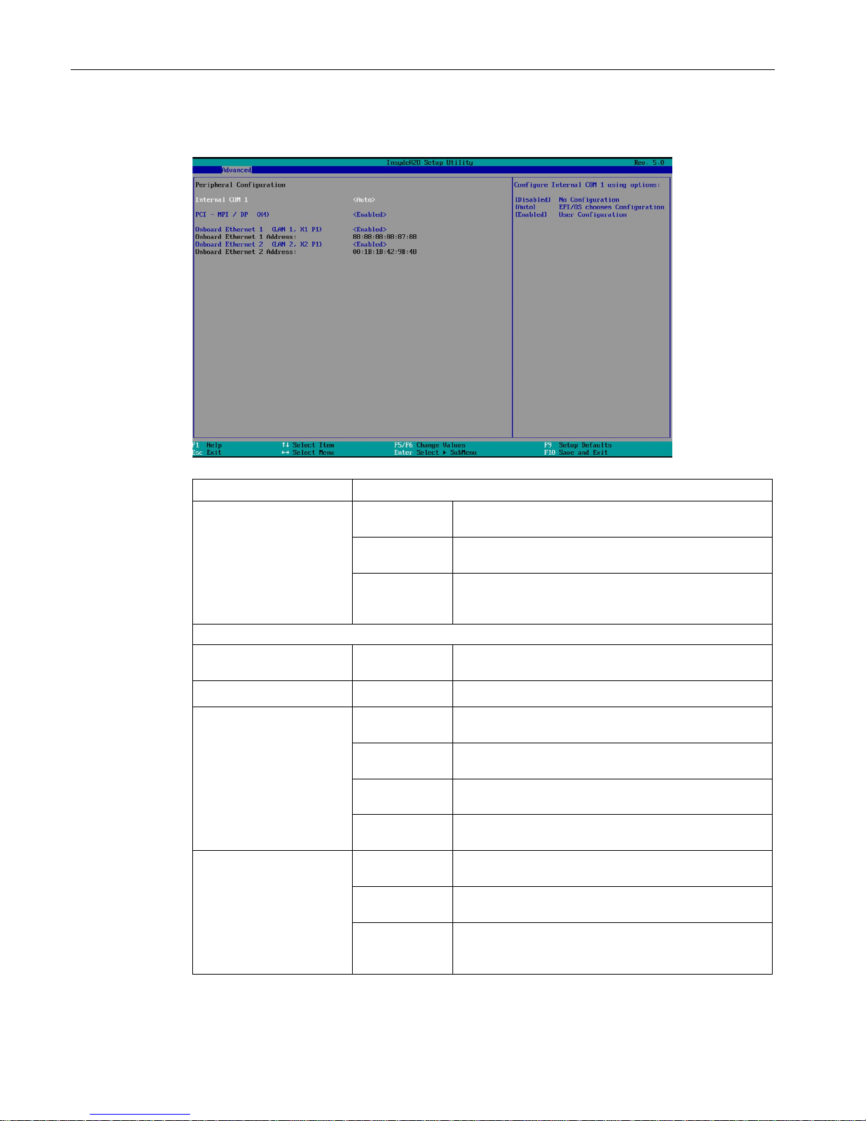
"Peripheral Configuration" submenu
Parameter
Meaning
Internal COM 1 Enabled Enables the serial port. You can then set the I/O base
address and the interrupt.
Disabled Disables the serial port. This releases the resources it
used.
Auto Automatically configures the serial port. BIOS switches
on the serial interface port.
Re-configuration allocates
the resources in the operating system.
The following Setup parameters are visible if ""Internal COM 1"" is enabled.
• Base I/O Address 6
2E8, 2F8,
3E8, 3F8
The I/O base address is pre-assigned and also
recommended.
• Interrupt 6
IRQ3, IRQ4 The interrupt is pre-assigned and also recommended.
• Transceiver Mode
1 6
Transceiver
Loopback
Mode for testing the hardware.
RS232 Non-isolated connection for short distances in
interference-free environment.
RS485
Half Duplex
Isolated connection for environment with EMC load.
RS485/422
Full Duplex
Isolated connection for environment with EMC load,
transmitting and receiving at the same time.
Internal COM 2 2 Enabled Enables the serial port. You can then set the I/O base
address and the interrupt.
Disabled Disables the serial port. This releases the resources it
used.
Auto 1 Automatically configures the serial port. BIOS switches
on the serial interface port.
Re-configuration allocates
the resources in the operating system.

BIOS Setup (SCU)
3.4 Advanced menu
BIOS Description
Operating Manual, 05/2016, A5E33664825-AB
17
Parameter
Meaning
The following Setup parameters are visible if "Internal COM 2" is enabled.
• Base I/O Address
2E8, 2F8, 3E8, 3F8 The I/O base address is pre-assigned and also
recommended.
• Interrupt
IRQ3, IRQ4
The interrupt is pre-assigned and also
recommended.
• Transceiver Mode 1
Transceiver
Loopback
Mode for testing the hardware.
RS232 Non-isolated connection for short distances in
interference-free environment.
RS485
Half Duplex
Isolated connection for environment with EMC
load.
RS485/422
Full Duplex
Isolated connection for environment with EMC
load, transmitting and receiving at the same time.
Internal LPT 4 Enabled Enables the parallel port. You can then set the I/O
base address, interrupt, mode and DMA channel.
Disabled Disables the parallel port. This releases the
resources it used.
Auto Automatically configures the parallel port. BIOS
switches on the parallel interface. Re-configuration
allocates the resources in the operating system.
Re-configuration also sets the mode.
The following Setup parameters are visible if "Internal LPT" is enabled.
• Base I/O Address
278, 378
The I/O base address is pre-assigned and also
recommended.
• Interrupt
IRQ7
The interrupt is pre-assigned and also
recommended.
• Mode
Sets the data transfer mode.
Output Only
Data output only.
EPP
Enhanced Parallel Port: Fast transfer mode of up to
2 Mbps for devices that are not printers, sending
and receiving of data.
The peripheral device must
support EPP.
ECP
Enhanced Capability Port: Fast transfer mode of up
to 2.4 Mbps for printers and scanners, sending and
receiving of data. The peripheral device must sup-
port ECP. The DMA channel is set with Plug&Play.
Bi-directional Data transfer in both directions for PS/2 compatible
devices.
• DMA Channel
DMA 1, DMA 2,
DMA 3
Sets the DMA channel of the parallel port.
 Loading...