

Page 1

SIMATIC IPC677E
SIMATIC
Industrial PC
SIMATIC IPC677E
Operating Instructions
04/2019
A5E45
Preface
Product description
1
Safety instructions
2
Mounting and connecting the
device
3
Commissioning the device
4
Operating the device
5
Expanding the device and
assigning device parameters
6
Maintaining and servicing
your device
7
Technical specifications
8
Dimension drawings
9
Standards and approvals
10
Hardware descriptions
A
Technical support
B
Markings and symbols
C
List of abbreviations
D
117996-AA
Page 2

Siemens AG
Division Digital Factory
Postfach 48 48
90026 NÜRNBERG
GERMANY
A5E45117996-AA
Ⓟ
Copyright © Siemens AG 2019.
All rights reserved
DANGER
indicates that death or severe personal injury will result if proper precautions are not taken.
WARNING
indicates that death or severe personal injury may result if proper precautions are not taken.
CAUTION
indicates that minor personal injury can result if proper precautions are not taken.
NOTICE
indicates that property damage can result if proper precautions are not taken.
WARNING
Siemens products may only be used for the applications described in the catalog and in the relevant technical
ambient conditions must be complied with. The information in the relevant documentation must be observed.
Legal information
Warning notice system
This manual contains notices you have to observe in order to ensure your personal safety, as well as to prevent
damage to property. The notices referring to your personal safety are highlighted in the manual by a safety alert
symbol, notices referring only to property damage have no safety alert symbol. These notices shown below are
graded according to the degree of danger.
If more than one degree of danger is present, the warning notice representing the highest degree of danger will
be used. A notice warning of injury to persons with a safety alert symbol may also include a warning relating to
property damage.
Qualified Personnel
The product/system described in this documentation may be operated only by personnel qualified for the specific
task in accordance with the relevant documentation, in particular its warning notices and safety instructions.
Qualified personnel are those who, based on their training and experience, are capable of identifying risks and
avoiding potential hazards when working with these products/systems.
Proper use of Siemens products
Note the following:
documentation. If products and components from other manufacturers are used, these must be recommended
or approved by Siemens. Proper transport, storage, installation, assembly, commissioning, operation and
maintenance are required to ensure that the products operate safely and without any problems. The permissible
Trademarks
All names identified by ® are registered trademarks of Siemens AG. The remaining trademarks in this publication
may be trademarks whose use by third parties for their own purposes could violate the rights of the owner.
Disclaimer of Liability
We have reviewed the contents of this publication to ensure consistency with the hardware and software
described. Since variance cannot be precluded entirely, we cannot guarantee full consistency. However, the
information in this publication is reviewed regularly and any necessary corrections are included in subsequent
editions.
04/2019 Subject to change
Page 3

Preface
Edition
Comment
04/2019
First edition
Purpose of the operating instructions
These operating instructions contain all the information you need for the installation,
electrical connection, commissioning and expansion of the SIMATIC IPC677E and to
maintain and repair the device. They are intended for the following qualified specialist
personnel:
● Installation personnel
● Commissioning engineers
● IT administrators
● Service and maintenance personnel
Basic knowledge required
A solid background in electrical installation, personal computers, Microsoft operating
systems and network technology is required to understand this manual. General knowledge
in the field automation control engineering is recommended.
Scope of the operating instructions
These operating instructions are valid for all order versions of the SIMATIC IPC677E.
History
The following editions of these operating instructions have already been published:
SIMATIC IPC677E
Operating Instructions, 04/2019, A5E45117996-AA
3
Page 4

Preface
Security information
Siemens provides products and solutions with industrial security functions that support the
secure operation of plants, systems, machines and networks.
In order to protect plants, systems, machines and networks against cyber threats, it is
necessary to implement – and continuously maintain – a holistic, state-of-the-art industrial
security concept. Siemens' products and solutions constitute one element of such a concept.
Customers are responsible for preventing unauthorized access to their plants, systems,
machines and networks. Such systems, machines and components should only be
connected to an enterprise network or the internet if and to the extent such a connection is
necessary and only when appropriate security measures (e.g. firewalls and/or network
segmentation) are in place.
For additional information on industrial security measures that may be implemented, please
visit (http://www.siemens.de/industrialsecurity).
Siemens' products and solutions undergo continuous development to make them more
secure. Siemens strongly recommends that product updates are applied as soon as they are
available and that the latest product versions are used. Use of product versions that are no
longer supported, and failure to apply the latest updates may increase customers' exposure
to cyber threats.
To stay informed about product updates, subscribe to the Siemens Industrial Security RSS
Feed under (http://www.siemens.de/industrialsecurity).
Disclaimer for third-party software updates
This product includes third-party software. Siemens AG only provides a warranty for
updates/patches of the third-party software, if these have been distributed as part of a
Siemens software update service contract or officially released by Siemens AG. Otherwise,
updates/patches are undertaken at your own risk. You can find more information about our
Software Update Service offer on the Internet at Software Update Service
(http://www.automation.siemens.com/mcms/automation-software/en/software-update-
service).
SIMATIC IPC677E
4 Operating Instructions, 04/2019, A5E45117996-AA
Page 5

Table of contents
Preface ...................................................................................................................................................... 3
1 Product description .................................................................................................................................. 11
1.1 Important instructions and manuals for operating the device ................................................. 11
1.2 Product highlights ................................................................................................................... 13
1.3 Applications ............................................................................................................................. 15
1.4 External design of the device .................................................................................................. 16
1.4.1 Side view, right ........................................................................................................................ 16
1.4.2 Side view, left .......................................................................................................................... 17
1.4.3 Status displays ........................................................................................................................ 19
1.5 Internal design of the device ................................................................................................... 21
1.6 Accessories and spare parts .................................................................................................. 22
1.6.1 Accessories: Hardware ........................................................................................................... 22
1.6.2 Accessories: Software ............................................................................................................ 23
2 Safety instructions ................................................................................................................................... 25
2.1 General safety instructions ..................................................................................................... 25
2.2 Note on transport and storage ................................................................................................ 27
2.3 Notes on mounting .................................................................................................................. 28
2.4 Notes on ambient and environmental conditions .................................................................... 28
2.5 Information on I/O devices ...................................................................................................... 30
2.6 Notes on device and system extensions ................................................................................ 31
3 Mounting and connecting the device........................................................................................................ 33
3.1 Preparing for mounting ........................................................................................................... 33
3.1.1 Scope of delivery .................................................................................................................... 33
3.1.2 Checking the delivery package ............................................................................................... 35
3.1.3 Identification data of the device .............................................................................................. 36
3.1.4 Mounting positions .................................................................................................................. 37
3.1.5 Preparing the mounting cutout ................................................................................................ 39
3.2 Mounting the device ................................................................................................................ 41
3.2.1 Installation guidelines ............................................................................................................. 41
3.2.2 Mounting the device with mounting clips ................................................................................ 42
3.3 Connecting the device ............................................................................................................ 46
3.3.1 Country-specific information on supply voltage ...................................................................... 46
3.3.2 Connection of equipotential-bonding cable ............................................................................ 47
3.3.3 Connecting the power supply ................................................................................................. 48
3.3.3.1 Connecting 100-240 VAC power supply ................................................................................. 48
3.3.3.2 Connecting the 24 VDC power supply .................................................................................... 50
SIMATIC IPC677E
Operating Instructions, 04/2019, A5E45117996-AA
5
Page 6

Table of contents
3.3.4 Connecting I/O devices .......................................................................................................... 52
3.3.5 Connecting the device to networks ........................................................................................ 53
3.3.6 Connecting Ethernet/USB strain relief ................................................................................... 54
4 Commissioning the device ....................................................................................................................... 55
4.1 Switching on the device ......................................................................................................... 55
4.2 Configuring automatic switch-on of device ............................................................................ 55
4.3 Switching off the device ......................................................................................................... 56
5 Operating the device ................................................................................................................................ 59
5.1 Multi-monitoring ...................................................................................................................... 59
5.2 Drive configurations ............................................................................................................... 59
5.2.1 RAID1 system ........................................................................................................................ 59
5.3 Operating RAID systems ....................................................................................................... 60
5.3.1 Display of a defective drive of a RAID system ....................................................................... 60
5.3.2 RAID1 system: Installation options for drives ........................................................................ 60
5.3.3 Configure the onboard RAID system ..................................................................................... 60
5.3.4 Monitoring the onboard RAID system with "Intel® Rapid Storage Technology" ................... 62
5.3.5 Integrating a new drive into the onboard RAID system ......................................................... 63
5.3.6 Data synchronization in the RAID system ............................................................................. 64
5.4 Monitoring of the device ......................................................................................................... 65
5.4.1 Monitoring functions ............................................................................................................... 65
5.4.2 SIMATIC IPC DiagBase ......................................................................................................... 66
5.4.3 SIMATIC IPC DiagMonitor ..................................................................................................... 66
5.5 Remote maintenance of the device ....................................................................................... 67
5.5.1 Remote maintenance functions ............................................................................................. 67
5.5.2 SIMATIC IPC Remote Manager ............................................................................................. 68
5.6 Trusted Platform Module (TPM) ............................................................................................. 69
5.7 Buffer memory NVRAM (optional) ......................................................................................... 69
6 Expanding the device and assigning device parameters ......................................................................... 71
6.1 Opening the Device ............................................................................................................... 71
6.2 Expansion cards .................................................................................................................... 73
6.2.1 Usable expansion cards ......................................................................................................... 73
6.2.2 Installing/removing expansion cards ...................................................................................... 73
6.3 Memory modules.................................................................................................................... 76
6.3.1 Usable memory modules ....................................................................................................... 76
6.3.2 Installing and removing memory module ............................................................................... 77
6.4 Drives ..................................................................................................................................... 79
6.4.1 Changing the drive in the removable tray .............................................................................. 79
6.4.2 Changing internal SSD .......................................................................................................... 81
6.4.3 Changing internal hard disk drive .......................................................................................... 84
6.4.4 Replacing a drive in the RAID system ................................................................................... 86
6.4.5 Replacing M.2 NVMe SSD ..................................................................................................... 87
SIMATIC IPC677E
6 Operating Instructions, 04/2019, A5E45117996-AA
Page 7

Table of contents
7 Maintaining and servicing your device ..................................................................................................... 89
7.1 Repair information ................................................................................................................... 89
7.2 Maintenance intervals ............................................................................................................. 90
7.3 Cleaning the Device Front ...................................................................................................... 91
7.4 Removing and installing hardware .......................................................................................... 92
7.4.1 Replacing device fans ............................................................................................................. 92
7.4.2 Replace power supply fan ...................................................................................................... 95
7.4.3 Changing the backup battery .................................................................................................. 98
7.4.4 Replace power supply .......................................................................................................... 100
7.4.5 Replacing the bus board ....................................................................................................... 102
7.4.6 Replacing the processor ....................................................................................................... 106
7.5 Installing operating system, software and drivers ................................................................. 109
7.5.1 Installing the operating system ............................................................................................. 109
7.5.2 Installing software and drivers .............................................................................................. 109
7.6 Configuring firmware/BIOS ................................................................................................... 110
7.7 Backing up data and changing partitions .............................................................................. 110
7.8 Recycling and disposal ......................................................................................................... 110
8 Technical specifications ......................................................................................................................... 111
8.1 Applicability of technical specifications ................................................................................. 111
8.2 General technical specifications ........................................................................................... 111
8.3 Current/power consumption and power supply .................................................................... 113
8.3.1 Current/power consumption of the system components ...................................................... 113
8.3.2 Technical specifications AC power supply (AC) ................................................................... 114
8.3.3 Technical specifications of direct voltage power supply (DC) .............................................. 114
8.4 Electromagnetic compatibility ............................................................................................... 115
8.5 Ambient conditions ................................................................................................................ 115
8.6 Technical specifications of the drives ................................................................................... 116
8.7 Technical specifications of the motherboard ........................................................................ 116
8.8 Technical specifications of graphics/display ......................................................................... 117
8.9 Technical specifications of the interfaces ............................................................................. 117
8.10 Technical specifications of the operating systems ............................................................... 119
9 Dimension drawings .............................................................................................................................. 121
9.1 Dimension drawing of 19" device with capacitive multi-touch screen .................................. 121
9.2 Dimension drawing of 22" device with capacitive multi-touch screen .................................. 122
9.3 Dimension drawing of 24" device with capacitive multi-touch screen .................................. 123
9.4 Dimension drawing of the expansion cards .......................................................................... 124
SIMATIC IPC677E
Operating Instructions, 04/2019, A5E45117996-AA
7
Page 8

Table of contents
10 Standards and approvals ....................................................................................................................... 125
10.1 CE marking .......................................................................................................................... 125
10.2 DIN ISO 9001 certificate and software license agreements ................................................ 126
10.3 UL approval .......................................................................................................................... 126
10.4 FCC (USA) ........................................................................................................................... 127
10.5 Canada ................................................................................................................................. 127
10.6 Australia / New Zealand ....................................................................................................... 128
10.7 Eurasion Customs Union EAC ............................................................................................. 128
10.8 Korea .................................................................................................................................... 128
A Hardware descriptions ........................................................................................................................... 129
A.1 Motherboard ......................................................................................................................... 129
A.1.1 Layout of the motherboard ................................................................................................... 129
A.1.2 Position of the interfaces on the motherboard ..................................................................... 130
A.2 Internal Interfaces ................................................................................................................ 131
A.2.1 Assignment of the internal interfaces ................................................................................... 131
A.2.2 Device fan supply (X512) ..................................................................................................... 131
A.2.3 Supply for the power supply fan (X515) ............................................................................... 132
A.2.4 Supply for the serial ATA drives (X516 - X521) ................................................................... 132
A.3 Bus board ............................................................................................................................. 133
A.3.1 Design and principle of operation of the bus board ............................................................. 133
A.3.2 Pin assignment 12 V power supply connection for expansion cards ................................... 134
A.4 External interfaces ............................................................................................................... 135
A.5 System resources ................................................................................................................ 136
A.5.1 Currently allocated system resources .................................................................................. 136
A.5.2 I/O address allocation .......................................................................................................... 136
A.5.3 Interrupt Assignments .......................................................................................................... 138
A.5.4 Exclusive PCI hardware interrupt ......................................................................................... 141
A.5.5 Memory address assignments ............................................................................................. 142
B Technical support .................................................................................................................................. 143
B.1 Service and support ............................................................................................................. 143
B.2 Troubleshooting ................................................................................................................... 144
B.2.1 Problems with device functions ............................................................................................ 144
B.2.2 Problems when booting the device ...................................................................................... 145
B.2.3 Problems with RAID systems ............................................................................................... 146
B.2.4 Problems when using expansion cards ............................................................................... 146
SIMATIC IPC677E
8 Operating Instructions, 04/2019, A5E45117996-AA
Page 9

Table of contents
C Markings and symbols ........................................................................................................................... 147
C.1 Overview ............................................................................................................................... 147
C.2 Safety .................................................................................................................................... 147
C.3 Operator controls .................................................................................................................. 147
C.4 Certificates, approvals and markings .................................................................................... 148
C.5 Interfaces .............................................................................................................................. 149
D List of abbreviations ............................................................................................................................... 151
D.1 Abbreviations ........................................................................................................................ 151
Index ...................................................................................................................................................... 155
SIMATIC IPC677E
Operating Instructions, 04/2019, A5E45117996-AA
9
Page 10

Table of contents
SIMATIC IPC677E
10 Operating Instructions, 04/2019, A5E45117996-AA
Page 11

1
Documentation
Contents
Source
com/cs/ww/en/view/109760621)
1.1 Important instructions and manuals for operating the device
Operating Instructions
Quick Install Guide Information on:
Current product information
Firmware/BIOS description
Windows® operating
system
• Product description
• Technical specifications
• Installation of the device
• Operation of the device
• Installing and removing hard-
ware
• Dimension drawings
• Operating Instructions of the
device
• Installation of the device
• Connecting the device to the
power supply
• Connecting I/O devices
• Switching the device on
• Current notes on the device
• Changes compared with these
Operating Instructions
Information on:
• Important firmware settings
• Firmware settings in the delivery
state
• Boot modes
Information on:
• Commissioning the operating
system
• Restoring the operating system
• Configuration of the operating
system
• Supplied data storage medium
• Online at:
SIMATIC IPC Documentation
(https://support.industry.siemens.
com/cs/ww/en/view/109760621)
• Supplied in printed form with the
device
• Supplied data storage medium
• Online at:
SIMATIC IPC Documentation
(https://support.industry.siemens.
• Supplied data storage medium
• Online at:
Firmware/BIOS description
(https://support.industry.siemens.
com/cs/ww/en/view/109760621)
• Supplied data storage medium
• Online at:
Microsoft® Windows® 10
(https://support.industry.siemens.
com/cs/ww/en/view/109749498)
SIMATIC IPC677E
Operating Instructions, 04/2019, A5E45117996-AA
11
Page 12

Product description
Documentation
Contents
Source
com/cs/ww/en/view/39129913)
com/cs/de/en/view/21766418)
/Default.aspx)
com/cs/ww/en/view/109751260)
1.1 Important instructions and manuals for operating the device
SIMATIC IPC DiagBase
SIMATIC IPC DiagMonitor
SIMATIC IPC Remote
Manager
SIMATIC IPC Image &
Partition Creator
Information on:
• Temperature monitoring
• Fan monitoring
• Monitoring drives
• Watchdog
• Operating hours counter
• Battery monitoring
Monitoring functions such as with
SIMATIC IPC DiagBase with additional extended functions.
Information on:
• Remote maintenance of
SIMATIC Industrial PCs (IPCs)
via a management PC.
• Using Intel ®Active Management
Technology (Intel® AMT).
Information on:
• Backup and recovery of files,
directories, drive partitions.
• Supplied data storage medium
• Online at:
SIMATIC IPC DiagBase
(https://support.industry.siemens.
com/cs/ww/en/view/109749690)
• Online at:
SIMATIC IPC DiagMonitor
(https://support.industry.siemens.
• Online at:
SIMATIC IPC Remote Manager
(http://support.automation
.siemens.com/WW/view
/en/48707158)
• Online at:
SIMATIC IPC Image Partition
Creator
(https://support.industry.siemens.
SIMATIC NET Industrial communication
SIMATIC Industrial PC
Panel Drivers and
Tools
Information on:
• Setting the brightness
• Configuration of the screen sav-
er
• Touch settings for resistive touch
and multi-touch
• Online at:
SIMATIC NET
(http://w3.siemens.com/mcms
/automation/en/industrialcommunications/Pages
• Online at:
SIMATIC Industrial PC Panel
Drivers and Tools V1.3 PDT
IPC/IFP with capacitive multitouch screen
(https://support.industry.siemens.
SIMATIC IPC677E
12 Operating Instructions, 04/2019, A5E45117996-AA
Page 13

Product description
Note
Depending on the
manual may differ from the features of your device.
1.2 Product highlights
1.2 Product highlights
The SIMATIC IPC677E is a powerful industrial PC. It is perfectly suited for PC applications
with high-level industry functionality.
Device view
configuration ordered the features and illustrations described in this
Maximum industrial compatibility for 24-hour continuous use in industrial environments
● Maximum processor power (in full configuration) without loss of power (throttling) at up to
+45 °C ambient temperature
● Full metal enclosure with high electromagnetic compatibility (EMC) for use in industry
● Independent industrial product design for high shock and vibration resistance
● CE marking for the industrial field
SIMATIC IPC677E
Operating Instructions, 04/2019, A5E45117996-AA
13
Page 14

Product description
1.2 Product highlights
High productivity through fast data processing
● 8th generation Intel® processors: Celeron, Core i3 and i7
● Graphics controller (630/P630) integrated in processor up to 4K Ultra HD resolution, three
independent graphic interfaces
● Maximum performance, e.g. through Intel C246 chip set, DDR4 memory (up to 64 GB)
with support of dual channel technology
● High data transfer rates, e.g. with PCI Express Gen 3 technology, USB 3.1 Gen 2
SuperSpeed (SuperSpeed+) (10 Gbps), M.2 NVMe
● Low noise level due to variable-speed fans
High system availability thanks to minimization of standstill times
● Hot swap (swapping of drive during operation) in removable drive bays in RAID systems
● Efficient event diagnostics through the SIMATIC IPC DiagBase or DiagMonitor monitoring
software (optional) and signaling software OPC/SNMP/LAN
● Remote control and remote maintenance of the device through iAMT (Intel® Active
Management Technology)
● SSD as 2.5" SATA or M.2 NVMe
● Preventative data backup with the SIMATIC IPC Image & Partition Creator
High investment protection
● Platform with embedded Intel components for long-term stability
● Availability: 3 to 6 years
● Assured spare parts availability: 5 years after end of production
● Certified for worldwide marketing (cULus)
● Support of legacy interfaces (COM)
● Compatible installation across device generations
● Worldwide service and support
Device variants
Devices with capacitive multi-touch screen display:
● 19" display, resolution: 1920 x 1080 pixels
● 22" display, resolution: 1920 x 1080 pixels
● 24" display, resolution: 1920 x 1080 pixels
SIMATIC IPC677E
14 Operating Instructions, 04/2019, A5E45117996-AA
Page 15

Product description
1.3 Applications
User-friendly application scenarios for commissioning, use and service
● High flexibility and expandability thanks to integrated interfaces and up to 2 slots (PCI and
PCI Express)
● Pre-installed and activated operating system
● Fast restoration of delivery state of the operating system (with supplied data storage
medium)
● Gbit LAN with teaming capability (3 x LAN 10/100/1000 Mbps connections)
● Service-friendly equipment design (modifications, service)
● Can be used flexibly in a wide variety of positions
1.3 Applications
The device offers industrial PC systems for high-performance and space-saving applications
in particular for manufacturers in the field of machine, plant and control cabinet engineering:
● Operating, process and visualization applications
● Industrial image processing
● Quality assurance and monitoring tasks
● Measurement, control and rule-based tasks
● Data acquisition and management
The SIMATIC IPC has the CE mark for use in industrial environments.
SIMATIC IPC677E
Operating Instructions, 04/2019, A5E45117996-AA
15
Page 16
Product description
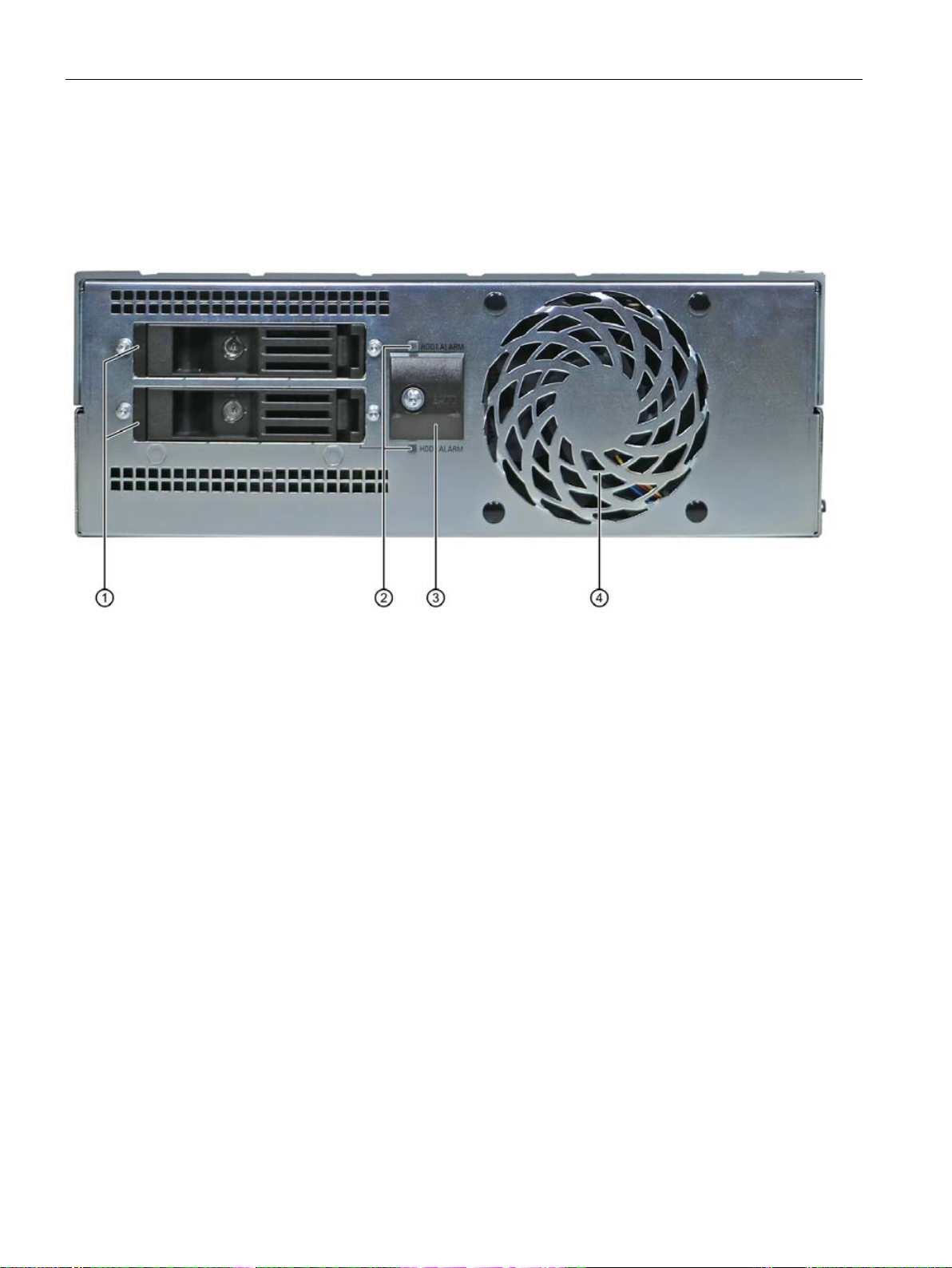
①
Removable drives
Slots for removable drives
②
RAID status indicators
HDD alarm
③
Battery compartment
CMOS backup battery
④
Front fan
1.4 External design of the device
1.4 External design of the device
1.4.1 Side view, right
SIMATIC IPC677E
16 Operating Instructions, 04/2019, A5E45117996-AA
Page 17
Product description
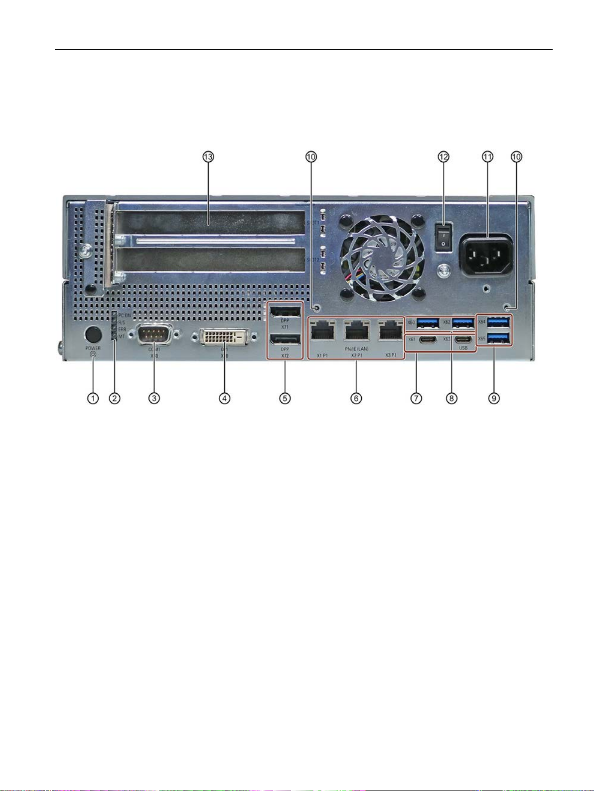
①
device is switched on with the on/off switch. You then do not need to press the on/off button.
②
4 status LEDs
Status display of the status indicators (Page 19)
③
COM1 X30
Serial interface
④
DVI/VGA X70
DVI-D connection for CRT or LCD monitor with DVI port
⑤
X71/X72
⑥
1.4 External design of the device
1.4.2 Side view, left
Connection side
On/off button The on/off button has three functions:
• Switch on the PC: Briefly press once
• Shut down operating system and switch off PC: Briefly press once
• Switch off PC without shutting down the operating system (hardware reset): Press for more
than 4 seconds.
Note: The BIOS setup entry "After Power Failure" has been set to "Power On". This means the
DisplayPort
3 × Ethernet
X1P1/X2P1/X3P1
DisplayPort connection for digital monitor
• X1P1, left: RJ45 Ethernet port 1 (exclusive PCI interrupt) with 10/100/1000 Mbps, iAMT ca-
pable
• X2P1, center: RJ45 Ethernet port 2 (shared PCI interrupt) with 10/100/1000 Mbps
• X3P1, right: RJ45 Ethernet port 3 (shared PCI interrupt) with 10/100/1000 Mbps
SIMATIC IPC677E
Operating Instructions, 04/2019, A5E45117996-AA
17
Page 18

Product description
⑦
2 × USB X61/X63
USB 3.1 GEN 2 Type C high current, backward compatible with USB 3.0/2.0/1.1
⑧
2 × USB X60/X62
USB 3.1 GEN 2 Type A high current, backward compatible with USB 3.0/2.0/1.1
⑨
2 × USB X64/X65
USB 3.1 GEN 2 Type A high current, backward compatible with USB 3.0/2.0/1.1
⑩
strain relief
⑪
V AC
⑫
symbol is pressed inward on the device. Position "OFF" is the delivery state.
⑬
al)
1.4 External design of the device
Fixing screws for
100 V AC to 240
On/off switch You switch on the device with the on/off switch. This requires that the BIOS setup entry "After
PCI/PCIe expan-
sion cards,
USB on expan-
sion card (option-
Power supply connection
Power Failure" is set to "Power On".
The on/off switch does not isolate the device from the power supply. Position "ON", when the "-)"
2 slots for expansion cards (Slot1/X101, Slot2/X102)
SIMATIC IPC677E
18 Operating Instructions, 04/2019, A5E45117996-AA
Page 19
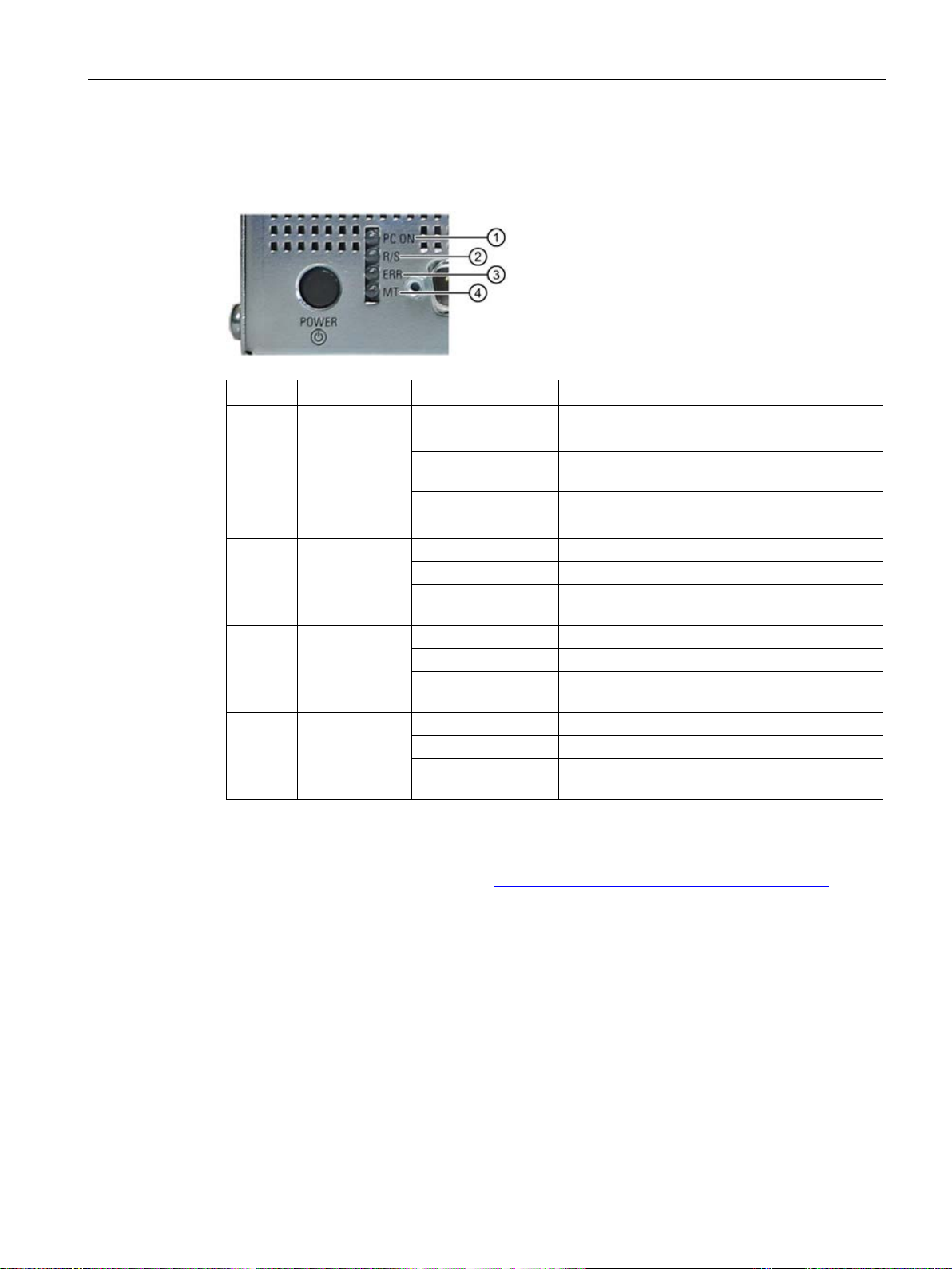
Product description
Position
Status indicator
Color
Description
①
Off - Green
BIOS ready to boot
green/yellow (1 Hz)
Yellow
Idle state
Flashing red (1 Hz)
Watchdog status display: active
Off - Green
Can be controlled by user program
(e.g. SoftPLC)
Off - Red
-
program (e.g. SoftPLC)
④
Off - Yellow
-
(e.g. SoftPLC)
1.4 External design of the device
1.4.3 Status displays
The status display consists of four multi-colored LEDs.
②
③
PC ON/WD
RUN/STOP
or L1
ERROR
or L2
MAINT
or L3
Flashing
Yellow Can be controlled by controller program
Flashing red Can be controlled by user program or controller
Red Can be controlled by controller program
BIOS in POST, power switch on
For additional information on controlling the LEDs or the NVRAM with a Windows operating
system, please refer to "Buffer memory NVRAM (optional) (Page 69)". Example programs for
controlling the LEDs under Windows operating systems are available on the Internet at the
following address: Technical support (https://support.industry.siemens.com/cs/ww/en/)
SIMATIC IPC677E
Operating Instructions, 04/2019, A5E45117996-AA
19
Page 20
Product description
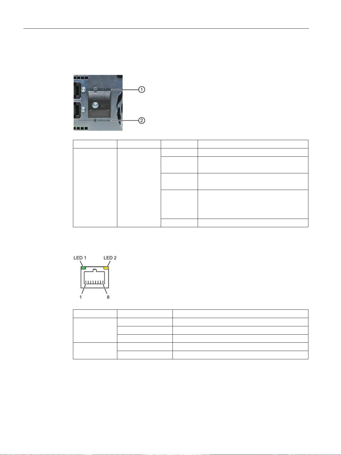
Display
Meaning
Color
Description
Both off
RAID is OK
up red
up red
RAID system in the RAID software".
Both flash
RAID is synchronized
Status indicator
Status
Meaning of the status
Off
10 Mbps
Lit green
100 Mbps
Lit orange
1000 Mbps
Lit
Connection exists
1.4 External design of the device
RAID status indicators in removable drive bay
Status indicator position, see also Side view, right (Page 16).
LED "HDDx
ALARM"
Ethernet status indicators
HDD alarm in
connection with
RAID and monitoring software
LED ① lights
LED ② lights
Both light up
red
HDD1 is not OK
HDD2 is not OK
RAID is not OK
For information on locating the hard disk, see
section "Displaying a defective hard disk of a
LED 1
LED 2
SIMATIC IPC677E
20 Operating Instructions, 04/2019, A5E45117996-AA
Flashes Activity
Page 21
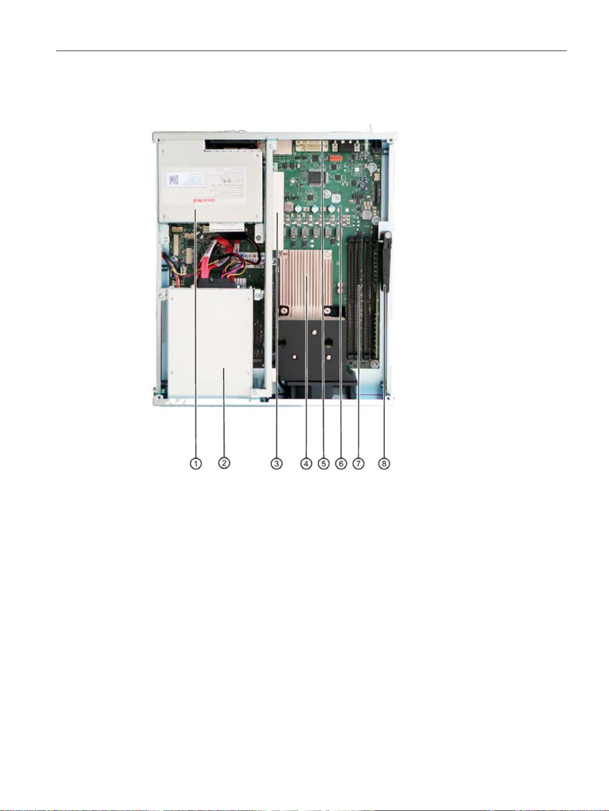
Product description
①
100 V AC to 240 V AC power supply
②
Slots for removable drives
③
Expansion card slots
④
Heat sink of the processor
⑤
Expansion card slots
⑥
Motherboard
⑦
Slots for memory modules
⑧
Retainer for expansion cards
1.5 Internal design of the device
1.5 Internal design of the device
SIMATIC IPC677E
Operating Instructions, 04/2019, A5E45117996-AA
21
Page 22

Product description
1.6 Accessories and spare parts
1.6 Accessories and spare parts
1.6.1 Accessories: Hardware
Accessories from Siemens are available for your device that are not included in the scope of
delivery.
Obtaining accessories and original spare parts via the SIEMENS Industry Mall
1. On the Internet, go to Industry Mall (https://mall.industry.siemens.com).
2. Log in with your customer data.
3. Select your user language.
4. Go to your device in the product catalog (tree structure on left):
"Automation technology > PC-based Automation > Industrial PC > Box PC> ..."
5. In the tree structure on the left, click on: SIMATIC IPC677E.
6. Select the "Accessories" tab in the display area.
SIEMENS spare parts services
Information on ordering, the provision and delivery of spare parts can be found under
"Industry Online Support: Spare parts services
(http://support.automation.siemens.com/WW/view/en/16611927)".
SIMATIC IPC677E
22 Operating Instructions, 04/2019, A5E45117996-AA
Page 23

Product description
Software
Description
(https://mall.industry.siemens.com).
Processors of the type i7 offer iAMT functionality.
1.6 Accessories and spare parts
1.6.2 Accessories: Software
The following software products, among others, can be additionally ordered for your device:
SIMATIC IPC Image & Partition Creator
SIMATIC IPC DiagMonitor The SIMATIC IPC DiagMonitor software offers additional
SIMATIC IPC Remote Manager The SIMATIC IPC Remote Manager enables the use of Intel®
This tool provides convenient and efficient functions for backing up and restoring the full content of memory cards, hard
disks and individual partitions (images).
The SIMATIC IPC Image & Partition Creator can be ordered
using the Siemens online ordering system
alarm and linking options in addition to the local monitoring
functions of the SIMATIC IPC DiagBase software and includes:
• The software for the stations to be monitored.
• A library for creating user-specific applications.
Active Management Technology (Intel® AMT).
Remote access to SIMATIC IPCs enables, for example, sys-
tem or program errors to be corrected as well as firmware/BIOS and program updates to be performed from a
control room (without deployment in the field).
Access is possible even if the operating system no longer
starts.
Further information on the software products and references to the online catalog and
ordering system (Industry Mall) can be found on the SIMATIC IPC software
(http://www.automation.siemens.com/mcms/pc-based-automation/en/industrial-
pc/expansion_components_accessories) homepage.
See also
Industry Mall (https://mall.industry.siemens.com)
SIMATIC IPC677E
Operating Instructions, 04/2019, A5E45117996-AA
23
Page 24

Product description
1.6 Accessories and spare parts
SIMATIC IPC677E
24 Operating Instructions, 04/2019, A5E45117996-AA
Page 25
2
WARNING
The installer of the system is responsible for the safety of a system in which the device is
integrated.
WARNING
Risk of electric shock
DANGER
Risk of lightning strikes
2.1 General safety instructions
There is a risk of malfunction which could result in death or serious injury.
• Ensure that only suitably qualified personnel perform the work.
Risk due to electric shock
Risk of lightning strikes
The on/off button and on/off switch do not fully disconnect the device from the supply
voltage.
There is also a risk of fire if the device or connecting lines are damaged.
• Always fully disconnect the device from the supply voltage before performing work on
the device or when the device will not be used over an extended period of time.
• For control cabinet mounting: Use a central, easily accessible AC circuit breaker close
to the device, if possible.
• When you install the device, make sure that the power supply connector is easily
accessible.
A lightning flash may enter the mains cables and data transmission cables and jump to a
person.
Death, serious injury and burns may result.
• Disconnect the device from the power supply in good time when a thunderstorm is
approaching.
• Do not touch power cables and data transmission cables during a thunderstorm.
• Keep sufficient distance from electric cables, distributors, systems, etc.
SIMATIC IPC677E
Operating Instructions, 04/2019, A5E45117996-AA
25
Page 26

Safety instructions
NOTICE
Possible functional restrictions in case of non-validated plant operation
Note
Burn-in effect and backlighting
The brightness of the backlighting deteriorates over the course of the screen's life cycle. A
permanent picture with bright screen objects leads to a burn
•
Note
Defective pixels in the display
The manufacturing process of modern displays does not currently guarantee that all pixels of
the display are perfect. It is therefore inevitable that the display will contain a
of defective pixels. This does not limit the function in any way provided the defective pixels
are not all in one location.
Note
Use in an industrial environment without additional protective measures
This device was designed for use in a normal industrial environment according to
IEC
NOTICE
Electrostatic sensitive devices (ESD)
2.1 General safety instructions
Avoiding functional restrictions
The device is tested and certified on the basis of the technical standards. In rare cases,
functional restrictions can occur during plant operation.
Validate the correct functioning of the plant to avoid functional restrictions.
TFT displays
-in effect.
Use a screen saver to extend the life of the screen and the backlighting and to prevent
the burn-in effect.
Use in industrial environments
60721-3-3.
ESD directive
Electrostatic sensitive devices can be labeled with an appropriate symbol.
small number
The device contains electronic components which may be destroyed by electrostatic
charge. This can result in malfunctions and damage to the machine or plant.
Take corresponding precautionary measures before you open the device.
SIMATIC IPC677E
26 Operating Instructions, 04/2019, A5E45117996-AA
Page 27

Safety instructions
NOTICE
Damage to the device during transport and storage
WARNING
Electric shock and fire hazard due to damaged device
NOTICE
Damage from condensation
2.2 Note on transport and storage
2.2 Note on transport and storage
Damage caused by transportation and storage
If a device is transported or stored without packaging, shocks, vibrations, pressure and
moisture may impact the unprotected unit. Damaged packaging indicates that ambient
conditions have already had a massive impact on the device and it may be damaged.
This may cause the device, machine or plant to malfunction.
• Keep the original packaging.
• Pack the device in the original packaging for transportation and storage.
Damage from condensation
A damaged device can be under hazardous voltage and trigger a fire in the machine or
plant. A damaged device has unpredictable properties and states.
Death or serious injury could occur.
• Avoid installing and commissioning a damaged device.
• Label the damaged device and keep it locked away. Send off the device for immediate
repair.
If the device is subjected to low temperatures or extreme fluctuations in temperature during
transportation, moisture could occur on or inside the HMI device (condensation).
Moisture can cause a short-circuit in electrical circuits and damage the device.
• Store the device in a dry place.
• Bring the device to room temperature before starting it up.
• Do not expose the device to direct heat radiation from a heating device.
• If condensation develops, wait approximately 12 hours or until the device is completely
dry before switching it on.
SIMATIC IPC677E
Operating Instructions, 04/2019, A5E45117996-AA
27
Page 28

Safety instructions
DANGER
Electrocution risk when control cabinet is open
NOTICE
Voided approvals
NOTICE
Ambient conditions and chemical resistance
2.3 Notes on mounting
2.3 Notes on mounting
Device in the control cabinet
When you open the control cabinet, there may be a dangerous voltage at certain areas or
components.
Touching these areas or components can cause death or serious bodily injury.
• Always disconnect the cabinet from the mains before opening it.
• Ensure that the power to the control cabinet cannot be turned on accidentally.
2.4 Notes on ambient and environmental conditions
Certifications and approvals
If the following conditions for system installation are not observed, approvals in accordance
with UL 61010-2-201 and EN 61010-2-201 are rendered void and there is a risk of
overheating and personal injury.
• You should observe the following information on ambient and environmental conditions.
Ambient and environmental conditions
Unsuitable environmental conditions can cause faults or damage the device.
Failure to comply nullifies the warranty in accordance with IEC/EN/UL 61010-2-201.
• Operate the device only in closed rooms.
• Only operate the device in the ambient conditions specified in the technical
specifications.
• Observe the permitted mounting positions of the device.
• Do not obstruct the venting slots of the device.
• Please note that when the device is operated in severe environments which are subject
to caustic vapors or gases, the provision of clean air is ensured.
• Clean the enclosure surface with a damp cloth and make sure that no water enters the
device.
SIMATIC IPC677E
28 Operating Instructions, 04/2019, A5E45117996-AA
Page 29

Safety instructions
CAUTION
Immunity to RF interference
2.4 Notes on ambient and environmental conditions
When you plan your project, you should make allowances for:
● Take note of the climatic and mechanical ambient conditions (Page 115).
● You must observe the Mounting positions (Page 37) when mounting the device.
● For installation in a cabinet, observe the SIMATIC setup guidelines as well as the relevant
DIN/VDE requirements or the applicable country-specific regulations.
● When the device is used in the programmable controller area in accordance with
IEC/EN/UL61010-2-201, note that the device is classified as "Open Equipment". An
IEC/EN/UL61010-2-201 compliant enclosure is therefore a mandatory requirement for
approval or operation according to IEC/EN/UL61010-2-201.
● The device must be installed in such a way that it is part of a restricted access location
(e.g. a locked control cabinet, control panel or server room).
● Always maintain a minimum clearance of 100 mm to the area of the ventilation slots and
do not cover the ventilation slots of the enclosure.
High frequency radiation
The device has an increased immunity to RF radiation according to the specifications on
electromagnetic compatibility in the technical specifications.
High frequency radiation, e g. from a cellular phone, can result in malfunctioning of the
device.
Persons are injured and the plant is damaged.
• Avoid high-frequency radiation.
• Remove radiation sources from the environment of the device.
• Switch off radiating devices.
• Reduce the radio output of radiating devices.
• Read the information on electromagnetic compatibility.
• Read the information in the technical specifications.
SIMATIC IPC677E
Operating Instructions, 04/2019, A5E45117996-AA
29
Page 30

Safety instructions
CAUTION
Fault caused by I/O devices
NOTICE
Damage through regenerative feedback
Note
Checking the regenerative feedback
When
•
•
•
2.5 Information on I/O devices
2.5 Information on I/O devices
The connection of I/O devices can cause faults in the device.
The result may be personal injury and damage to the machine or plant.
• Only connect I/O devices which are approved for industrial applications in accordance
with EN 61000-6-2 and IEC 61000-6-2.
• I/O devices that are not hotplug-capable may only be connected after the device has
been disconnected from the power supply.
Regenerative feedback of voltage to ground by a connected or installed component can
damage the device.
Connected or built-in I/Os, for example, a USB drive, are not permitted to supply any
voltage to the device.
Regenerative feedback is generally not permitted.
measuring the counter emf, remember the following:
The computer in question must be turned off and the power supply connector must be
plugged in.
During the measurement, all cables from the plant to the computer should be connected.
All other components in the plant must be active.
SIMATIC IPC677E
30 Operating Instructions, 04/2019, A5E45117996-AA
Page 31

Safety instructions
CAUTION
Fire hazard due to overheating of the device
NOTICE
Damage caused by device and system extensions
NOTICE
"Open Equipment" IEC/EN/UL61010
2.6 Notes on device and system extensions
2.6 Notes on device and system extensions
Device and system extensions
Expansion cards generate additional heat. The device can overheat or cause a fire.
• Observe the safety and installation instructions for the expansion cards.
• Observe the max. permissible power consumption values.
Device and system expansions may contain faults and affect the entire device, machine or
plant. They may also violate safety rules and regulations regarding radio interference
suppression.
If you install or replace device or system expansions and damage your device, the warranty
is voided.
• Always disconnect the power plug before you open the device.
• Only install device or system expansions designed for this device.
• Observe the information on "Electromagnetic compatibility" provided in the technical
Contact your technical support team or the point of sale to find out which device and system
expansions are suitable for installation.
The device is designed for use as a programmable controller, OpenType according to
IEC/EN/UL 61010-2-201. The installation of the device in a fire protection housing in
accordance with IEC/EN/UL 61010-2-201 is therefore a mandatory requirement for
approval or operation.
Limitation of liability
● Observe the installation instructions for expansion components in the associated
specifications.
documentation.
● UL approval of the device only applies when the UL-approved components are used
according to their "Conditions of Acceptability".
● We are not liable for functional limitations caused by the use of third-party devices or
components.
SIMATIC IPC677E
Operating Instructions, 04/2019, A5E45117996-AA
31
Page 32

Safety instructions
2.6 Notes on device and system extensions
SIMATIC IPC677E
32 Operating Instructions, 04/2019, A5E45117996-AA
Page 33

3
3.1 Preparing for mounting
3.1.1 Scope of delivery
Device and hardware for the device
● Panel PC SIMATIC IPC677E
● Mounting clips
● Strain relief
● Power plug latch
● USB stick
Optional:
● DiagMonitor
● Image & Partition Creator
● Power supply cable
Supplied data medium
On the supplied data medium (read-only), you can find:
● Software and tools to restore your ordered Microsoft® Windows® operating system.
● Device drivers for installation in operating systems
● SIMATIC IPC677E Quick Install Guide
● SIMATIC IPC677E Operating Instructions
● Product information
● Firmware/BIOS description
● Operating instructions for your ordered Microsoft® Windows® operating system on this
device
SIMATIC IPC677E
Operating Instructions, 04/2019, A5E45117996-AA
33
Page 34

Mounting and connecting the device
3.1 Preparing for mounting
Operating system
Depending on the ordered device configuration, the device comes with an installed operating
system.
● Microsoft® Windows® 10
(https://support.industry.siemens.com/cs/ww/de/view/109749498/en?dl=en)
● Without operating system
Installed software
● Monitoring software SIMATIC IPC DiagBase (only with installed Microsoft® Windows®
operating system)
● SIMATIC Panel Driver and Tools (only with installed Microsoft® Windows® operating
system)
You will find the latest information on additional software for your device under: Accessories
and spare parts (Page 22)
Printed documents
● SIMATIC IPC677E Quick Install Guide
● Product Information "Important notes on your device"
● SIMATIC IPC/PG Quality Control Report
SIMATIC IPC677E
34 Operating Instructions, 04/2019, A5E45117996-AA
Page 35

Mounting and connecting the device
WARNING
Electric shock and fire hazard due to damaged device
3.1 Preparing for mounting
3.1.2 Checking the delivery package
Damaged devices due to improper storage or transport may lead to personal injury and/or
substantial damage to equipment.
• You must observe the warnings in "Note on transport and storage (Page 27)".
Procedure
1. Check the packaging and package contents for visible transport damage.
If any transport damage is present at the time of delivery, lodge a complaint at the
shipping company in charge. Have the shipper confirm the transport damage
immediately.
2. Unpack the device at its installation location.
3. Keep the original packaging in case you have to transport the unit again.
4. Check the Scope of delivery (Page 33) and any accessories you may have ordered for
completeness and damage. Please inform the delivery service immediately if the package
contents are incomplete or damaged or do not correspond with your order. Fax the
enclosed form "SIMATIC IPC/PG Quality Control Report".
5. Please keep the enclosed documentation in a safe place. It belongs to the device. You
need the documentation when you commission the device for the first time.
6. Write down the Identification data of the device (Page 36) identification data of the device.
SIMATIC IPC677E
Operating Instructions, 04/2019, A5E45117996-AA
35
Page 36

Mounting and connecting the device
3.1 Preparing for mounting
3.1.3 Identification data of the device
The device can be clearly identified with the help of this identification data in case of repairs
or loss.
The following illustrations are examples. The data of your device may differ from the data in
these examples.
Nameplate
The following image shows the nameplate on the SIMATIC IPC677E as an example.
COA label
Microsoft Windows "Product Key" is the "Certificate of Authenticity" (COA):
The COA label is only available for devices delivered with Microsoft® Windows® operating
system installed and is located on the rear of the device.
Example of COA label for the Microsoft® Windows® 10 operating system:
The Microsoft® Windows® 10 COA label has an additional security feature which conceals
part of the product key.
● The scratch-off panel consists of a small transparent label with a silver-colored scratch
coating, which was applied to conceal part of the 25-character product key. This scratchoff panel is designed to protect the product key from being obtained and used by
unauthorized third parties.
● You usually do not need this product key for commissioning because a valid product key
has already been integrated into the pre-installed operating system.
See also
Important instructions and manuals for operating the device (Page 11)
SIMATIC IPC677E
36 Operating Instructions, 04/2019, A5E45117996-AA
Page 37

Mounting and connecting the device
NOTICE
"Open Equipment" IEC/EN/UL61010
Note
Operation in closed rooms
The device is approved for
(Page
Note
Mounting precautions
•
3.1 Preparing for mounting
3.1.4 Mounting positions
The device is designed for use as a programmable controller, OpenType according to
IEC/EN/UL 61010-2-201. The installation of the device in a fire protection housing in
accordance with IEC/EN/UL 61010-2-201 is therefore a mandatory requirement for
approval or operation.
The following mounting positions are permitted for the device.
For information on the maximum permissible ambient temperatures during operation, refer to
section "Ambient conditions (Page 115)".
Mounting positions according to UL61010
operation in closed rooms only. Note the Ambient conditions
115).
Mounting in horizontal format
The total power for USB and PCI/PCIe expansions cannot exceed 30 W.
SIMATIC IPC677E
Operating Instructions, 04/2019, A5E45117996-AA
37
Page 38

Mounting and connecting the device
Note
Operation in closed rooms
The device is approved for operation in closed rooms only. Note the
(Page
Note
Mounting precautions
•
3.1 Preparing for mounting
Additional mounting positions according to UL61010/CSA 22.2 No. 142
Ambient conditions
115).
Mounting in vertical format
The total power for USB and PCI/PCIe expansions cannot exceed 30 W.
SIMATIC IPC677E
38 Operating Instructions, 04/2019, A5E45117996-AA
Page 39

Mounting and connecting the device
Note
Stability of the mounting cutout
The material in the area of the mounting cutout must provide sufficient strength to guarantee
the enduring and safe mounting of the HMI device.
The force of the clamps or operation of the device may not lead to deformation of the
material in order to achieve the degrees of protection described below.
Note
Read the information in the section "
3.1 Preparing for mounting
3.1.5 Preparing the mounting cutout
Installation guidelines (Page 41)".
Requirements for complying with degree of protection
The degree of protection of the HMI device can only be guaranteed if the following
requirements are met:
● Material thickness at the mounting cutout for IP65 degree of protection, or for
enclosure type 4X/type 12 (indoor use only): 2 mm to 6 mm
● Permissible deviation from plane at the mounting cutout: ≤ 0.5 mm
This condition must be fulfilled for the mounted HMI device.
● Permissible surface roughness in the area of the mounting seal: ≤ 120 µm (R
Dimensions of the mounting cutout
120)
z
SIMATIC IPC677E
Operating Instructions, 04/2019, A5E45117996-AA
39
Page 40

Mounting and connecting the device
Mounting cutout
Multi-touch device 2
19"
22"
24"
Width w 1
448+1 mm
513+1 mm
569+1 mm
Height h 1
278+1 mm
315+1 mm
347+1 mm
1
2
Device with capacitive multi-touch screen
3.1 Preparing for mounting
Width and height must be interchanged for mounting in vertical format.
Installation depth
Information on the overall depth is available in the section "Dimension drawings
(Page 121)".
SIMATIC IPC677E
40 Operating Instructions, 04/2019, A5E45117996-AA
Page 41

Mounting and connecting the device
WARNING
Dangerous voltage and fire hazard
NOTICE
Insufficient load carrying capacity
NOTICE
Incorrect fixing elements
Note
•
•
•
•
•
•
•
3.2 Mounting the device
3.2 Mounting the device
3.2.1 Installation guidelines
Procedure during installation and mounting
Improper actions during installation and assembly may lead to personal injury and/or
substantial damage to equipment.
You should observe the installation and assembly notes under:
• Notes on mounting (Page 28)
• Notes on ambient and environmental conditions (Page 28)
If the wall it is mounted on does not have a sufficient load-bearing capacity, the device may
fall and be damaged.
• Ensure that the mounting surface on the wall can bear four times the total weight of the
The device may not be securely fitted if you use fixing elements other than those specified
below for mounting. The device can fall and may be damaged.
• Use only the specified fixing elements.
device, including fixing elements.
See the notes under Preparing the mounting cutout (Page 39).
For installation in control cabinets, note the SIMATIC setup guidelines as well as the
relevant DIN/VDE requirements or the country-specific regulations.
Ensure that the device is classified as "Open Equipment" when using it in the area of
Industrial Control Equipment (UL 61010). A UL 61010 compliant enclosure is therefore a
mandatory requirement for approval or operation according to UL 61010.
Provide adequate volume in the control cabinet for air circulation and heat transport.
Keep at least 5 cm distance between the device and control cabinet.
The ventilation slots of the device may not be covered or obstructed.
Ensure there is enough clearance in the control cabinet to allow the backplane cover to
be removed.
Equip the control cabinet with struts for stabilizing the mounting cut-out. Install struts
where necessary.
SIMATIC IPC677E
Operating Instructions, 04/2019, A5E45117996-AA
41
Page 42

Mounting and connecting the device
Note
If the mounting seal is damaged or protrudes from the device, the guaranteed degree of
protection is not ensured.
It is prohibited from mounting the device if the mount
3.2 Mounting the device
See also
Ambient conditions (Page 115)
Mounting positions (Page 37)
3.2.2 Mounting the device with mounting clips
Positions of the mounting clips
To achieve the degree of protection for the device, the positions for the mounting clips
shown below must be adhered to.
Requirement
● All packaging components and protective films have been removed from the device.
● To install the device, you need the mounting clips from the accessory kit.
Procedure
● The mounting seal on the front of the device is not managed.
ing seal is damaged.
SIMATIC IPC677E
42 Operating Instructions, 04/2019, A5E45117996-AA
Page 43

Mounting and connecting the device
3.2 Mounting the device
1. Working from the front, insert the device into the mounting cut-out.
2. Make sure that all four spring fasteners latch fully into place on the upper and lower side
of the device. If necessary, press the device again carefully into the mounting slot at the
place that is not fully latched into position.
3. Insert a mounting clip into the cutout provided on the device.
Note the correct position of the mounting clips.
4. To secure the mounting clip, tighten the grub screw with the slot screwdriver, torque 0.5
Nm.
SIMATIC IPC677E
Operating Instructions, 04/2019, A5E45117996-AA
43
Page 44

Mounting and connecting the device
Device
Position
3.2 Mounting the device
5. Repeat steps 3 and 4 until all mounting clips are securely fastened.
6. Check the fit of the mounting seal.
Position of the mounting clips for multi-touch devices
Fasten the mounting clips to the positions as illustrated.
24" display
22" display
SIMATIC IPC677E
44 Operating Instructions, 04/2019, A5E45117996-AA
Page 45

Mounting and connecting the device
Device
Position
3.2 Mounting the device
19" display
SIMATIC IPC677E
Operating Instructions, 04/2019, A5E45117996-AA
45
Page 46

Mounting and connecting the device
3.3 Connecting the device
3.3 Connecting the device
3.3.1 Country-specific information on supply voltage
USA and Canada
Supply voltage 120 V / 230 V / 240 V AC
Ensure that the power cords used are rated for the maximum current input and ambient
temperature of the device and meet the requirements of the following standards:
● ANSI/UL 817
● CSA C22.2 No. 21
Ensure that the device connectors, connection sockets and connection materials are rated
for the maximum current input and ambient temperature of the device and meet the
requirements of the following standards:
● ANSI/UL 498 and CSA C22.2 No. 42
● CSA C22.2 No. 182.1
● CSA C22.2 No. 182.2
● CSA C22.2 No. 182.3
For countries other than the USA and Canada
Supply voltage 230 V AC
This device is supplied with a safety-tested power cord and may only be connected to a
grounded SCHUKO socket outlet.
If you do not use the power supply cord, use a flexible cable that is rated for the maximum
current consumption and highest ambient temperature of the device and complies with the
safety regulations of the country in which the device is installed.
The power supply cord and the plug connector must bear the prescribed markings.
SIMATIC IPC677E
46 Operating Instructions, 04/2019, A5E45117996-AA
Page 47

Mounting and connecting the device
3.3 Connecting the device
3.3.2 Connection of equipotential-bonding cable
A low-resistance ground connection ensures that interference signals generated by external
power supply cables, signal cables or cables to the I/O modules are safely discharged to
ground.
The connection for functional earthing on a device has a large surface, makes contact over a
large area and is marked with the following symbol:
Requirements
For the equipotential bonding connection, you require:
● A T20 screwdriver
● An equipotential bonding cable with a minimum cross-section of 2.5 mm
Procedure
2
1. Connect the marked equipotential bonding connection (M4 thread) of the device with the
equipotential bonding cable.
Make sure the equipotential bonding cable has contact with the enclosure over a large
area.
2. Connect the equipotential bonding cable with the central grounding point of the control
cabinet.
Make sure the equipotential bonding cable has contact with the central grounding point
over a large area.
SIMATIC IPC677E
Operating Instructions, 04/2019, A5E45117996-AA
47
Page 48

Mounting and connecting the device
WARNING
Injury to persons or damage to property when operated on an incorrect power supply
system
WARNING
Safety regulations- connecting cable
WARNING
Risk of electric shock
Note
The varying voltage power supply module is designed for operation on 120/230/240 V AC
networks. The setting of the voltage range takes place automatically.
3.3 Connecting the device
3.3.3 Connecting the power supply
3.3.3.1 Connecting 100-240 VAC power supply
If you connect the device to an unsuitable power supply, the device receives voltages and
currents that are too high or too low.
Injuries to persons, malfunctions or a damage to the device can result.
• The permissible rated voltage of the device must match the local supply voltage.
• Operate the device only in grounded power supply networks (TN networks in
accordance with VDE 0100, Part 100 or IEC 60364-1).
• Operation in non-grounded or impedance-grounded networks is not permitted.
Use only AC or DC connecting cables which comply with the local safety regulations.
Otherwise, there is a risk of fire and electric shock. This can result in personal injury or
property damage.
• Ensure that the AC or DC connecting cables comply with the safety regulations of the
country in which the device is installed and bear the marks required in each case.
• Connect the protective conductor in accordance with the operating instructions.
The on/off button and on/off switch do not fully disconnect the device from the mains.
There is also a risk of fire if the device or connecting lines are damaged.
• Always fully disconnect the device from the line voltage before performing work on the
device or when the device will not be used over an extended period of time.
• For control cabinet mounting: Use a central AC circuit breaker as near as possible to the
device and connect the device to a protective conductor.
• When you install the device, make sure that the power supply connector is easily
accessible.
SIMATIC IPC677E
48 Operating Instructions, 04/2019, A5E45117996-AA
Page 49

Mounting and connecting the device
3.3 Connecting the device
Requirement
● You have observed the information under "Country-specific information on supply voltage
(Page 46)".
● Screwdriver T10
Procedure
1. Make sure that the ON/OFF switch is in position "I" (Off) to avoid unintentional startup of
the device when you plug in the power cord.
2. Connect the appliance connector to the device.
3. Connect the power cable with the safety power outlet.
4. If necessary, install the enclosed cable grip.
SIMATIC IPC677E
Operating Instructions, 04/2019, A5E45117996-AA
49
Page 50

Mounting and connecting the device
WARNING
Safety regulations- connecting cable
WARNING
Risk of electric shock
Note
Safety extra-low voltage (SELV)
•
•
•
3.3 Connecting the device
3.3.3.2 Connecting the 24 VDC power supply
Use only AC or DC connecting cables which comply with the local safety regulations.
Otherwise, there is a risk of fire and electric shock. This can result in personal injury or
property damage.
• Ensure that the AC or DC connecting cables comply with the safety regulations of the
country in which the device is installed and bear the marks required in each case.
• Connect the protective conductor in accordance with the operating instructions.
The on/off button and on/off switch do not fully disconnect the device from the mains.
There is also a risk of fire if the device or connecting lines are damaged.
• Always fully disconnect the device from the line voltage before performing work on the
device or when the device will not be used over an extended period of time.
• For control cabinet mounting: Use an easily accessible central disconnect switch as
near as possible to the device and connect the device to a protective conductor.
• When you install the device, make sure that the power supply connector is easily
accessible.
The device must only be connected to a 24 V DC power supply which meets the
requirements of safe extra-low voltage (SELV) according to IEC/EN/DIN EN 60950-1.
A protective conductor must also be used.
The conductors must withstand the short-circuit current of the 24 V DC power source, so
that a short-circuit will not damage the cable.
Only connect cables with a minimum cross-section of 1.3 mm2 (AWG16) and a maximum
cross-section of 3.3 mm
2
(AWG12).
SIMATIC IPC677E
50 Operating Instructions, 04/2019, A5E45117996-AA
Page 51

Mounting and connecting the device
Note
Reverse-polarity protection
The 24
24
After the power supply has been connected correctly, the device will again be ready to
operate.
3.3 Connecting the device
Requirement
● You have observed the information under "Country-specific information on supply voltage
(Page 46)".
● The 24 V DC power source must be adapted to the input data of the device
(see Technical specifications (Page 111)).
Procedure
1. Make sure that the ON/OFF switch is in the position "I" (OFF) to prevent unintentional
startup of the device when it is connected to the 24 V DC power supply.
2. Switch off the external 24 V DC power supply.
3. Connect the 24 V DC plug connector to the device.
Observe the correct polarity of the contacts:
① Protective conductor
② Ground
③ 24 V DC
4. If necessary, install the enclosed cable grip.
5. Secure the 24 V DC cable to the cable grip using a cable tie.
V DC power supply is protected against polarity reversal. When you confuse the
V DC connecting cables and ground, the device is not damaged but does not switch on.
SIMATIC IPC677E
Operating Instructions, 04/2019, A5E45117996-AA
51
Page 52

Mounting and connecting the device
CAUTION
Fault caused by I/O devices
Note
Use the original connections of the I/O to be
Motherboard
DPP1
DPP2
DVI-D
Variant 1
DP X -
-
DVI
X 1) - -
VGA
X 2) - -
DP - X
-
DVI - X 1)
-
VGA - X 2)
-
3.3 Connecting the device
3.3.4 Connecting I/O devices
The improper connection of I/O devices can cause faults in the device.
The result may be personal injury and damage to the machine or plant.
• You should observe the warnings relating to the connection of I/O devices in
"Information on I/O devices (Page 30)".
Procedure
connected without adapters or extensions.
1. Connect the I/O devices to the respective interfaces.
Information on the position of the interfaces is available in "Side view, left (Page 17)".
2. Secure the cables with the strain relief.
See: Connecting Ethernet/USB strain relief (Page 54)
Connecting several monitors (multi-monitoring)
You will find up to three ports on the rear of the device for connecting monitors. These ports
are connected to the motherboard.
Parameter assignment is performed by means of the Control Panel in Windows®.
The IPC is factory set for multi-monitoring. If needed, you can configure the multi-monitoring
function and the output of the boot screen in the firmware settings, see "Multi-monitoring
(Page 59) ".
The following table shows the various connection options for the monitors on the device
interfaces.
Monitor 1
Monitor 2
SIMATIC IPC677E
52 Operating Instructions, 04/2019, A5E45117996-AA
Page 53

Mounting and connecting the device
Motherboard
DPP1
DPP2
DVI-D
Variant 2
DP X -
-
VGA
X 2) - -
DP - -
-
DVI - -
X
VGA - -
-
1)
2) - via DP-VGA adapter
3.3 Connecting the device
Monitor 1
DVI X 1) - -
Monitor 2
- via DP to DVI-D adapter
3.3.5 Connecting the device to networks
The following options are available for the integration in existing or planned system
environments or networks:
Ethernet
The integrated Ethernet port (10/100/1000 Mbps) can also be used for communication and
data exchange with automation devices such as SIMATIC S7.
This functionality requires the "SOFTNET S7" software package.
PROFINET
PROFINET can be operated via
● Standard Ethernet interfaces (RT)
Additional information
Additional information is available in the catalog and the online ordering system Technical
support (https://support.industry.siemens.com/cs/ww/en/).
See also
SIMATIC NET (http://w3.siemens.com/mcms/automation/en/industrielle-
kommunikation/Seiten/Default.aspx)
SIMATIC IPC677E
Operating Instructions, 04/2019, A5E45117996-AA
53
Page 54

Mounting and connecting the device
3.3 Connecting the device
3.3.6 Connecting Ethernet/USB strain relief
The Ethernet/USB strain relief supplied in the product package is used to prevent accidental
removal of the Ethernet cable and Industrial Ethernet FastConnect connector from the
device. You need two cable ties to use the strain relief. In addition to the Ethernet cables,
you can also use this strain relief to protect the four USB cables from inadvertent removal.
To secure the Ethernet strain relief, you will need a T10 screwdriver.
Procedure
1. Secure the Ethernet/USB strain relief with two oval-head screws M3 ① to the device
housing.
2. Connect the network and USB cables with the device and secure the connectors to the
strain relief with cable ties
3. Secure the connectors of the COM and DVI connection by screwing the connectors.
②.
SIMATIC IPC677E
54 Operating Instructions, 04/2019, A5E45117996-AA
Page 55

4
4.1 Switching on the device
Requirements for commissioning
● The following hardware is connected:
– One USB keyboard
– One USB mouse
● The protective conductor is connected.
● The connection cables are plugged in correctly.
● An operating system is installed. Information on commissioning Microsoft® operating
systems can be found in the documentation on the supplied data storage medium.
● The device is connected to the power supply, see "Connecting the power supply
(Page 48)".
Switching on the device
1. Switch on the on/off switch on the left side of the device (position | ).
2. Press the on/off button on the left side of the device.
Information on the position of the switch and button can be found at "Side view, left
(Page 17)".
Commissioning the installed Windows® operating system
You can find information on first startup of the device and commissioning the installed
Windows® operating system in the documentation on the supplied data storage medium,
see "Important instructions and manuals for operating the device (Page 11)".
4.2 Configuring automatic switch-on of device
In the firmware settings you can specify that the device automatically starts up again after a
separation from the mains voltage of at least 20 ms as soon as the mains voltage is
available again.
Configure this function with the firmware setting (Setup Utility > Advanced > PCH-IO
Configuration):
● State After G3
The exact minimum supply voltage downtime that is required is dependent on the device
equipment and the application.
You can find information on the configuration of this function in the detailed firmware/BIOS
description under "Important instructions and manuals for operating the device (Page 11)".
SIMATIC IPC677E
Operating Instructions, 04/2019, A5E45117996-AA
55
Page 56

Commissioning the device
WARNING
Risk of electric shock
4.3 Switching off the device
4.3 Switching off the device
Shutting down the operating system
For active operating system:
● Shut down the operating system properly.
For inactive operating system
● Briefly press the on/off button (unless otherwise configured in the power options).
Information on the position of the button is available under: "Side view, left (Page 17)".
Result
The operating system is shut down. The "POWER" status indicator is lit yellow. The device is
switched off but not fully disconnected from the line voltage.
Fully disconnecting the device from the line voltage
The on/off button and on/off switch do not fully disconnect the device from the mains.
There is also a risk of fire if the device or connecting lines are damaged.
• Always fully disconnect the device from the line voltage before performing work on the
device or when the device will not be used over an extended period of time.
• For control cabinet installation: Use a central, easily accessible AC circuit breaker close
to the device, if possible.
• When you install the device, make sure that the power supply connector is easily
accessible.
Shut down the operating system and unplug the power plug from the rear of the device, see
"Side view, left (Page 17)".
The device is switched off and fully disconnected from the line voltage. No trickle current is
flowing.
SIMATIC IPC677E
56 Operating Instructions, 04/2019, A5E45117996-AA
Page 57

Commissioning the device
NOTICE
Data loss
4.3 Switching off the device
Hardware reset
With the hardware reset, you can restart the device if it does no longer respond to keyboard
or mouse input.
Any running operating system will not shut down safely.
If a hardware reset is performed, the device undergoes a hard reboot.
• Data in the main memory is deleted.
• Data on the hard disk drive may be lost.
• The device may be damaged.
Perform a hardware reset only in the case of an emergency.
Procedure
See also
1. Press the on/off button for more than 4 seconds. The unit switches off.
Information on the position of the buttons is available under: "Side view, left (Page 17)".
General safety instructions (Page 25)
SIMATIC IPC677E
Operating Instructions, 04/2019, A5E45117996-AA
57
Page 58

Commissioning the device
4.3 Switching off the device
SIMATIC IPC677E
58 Operating Instructions, 04/2019, A5E45117996-AA
Page 59

5
Note
Information on graphics cards which support multi
local contact person, see "
5.1 Multi-monitoring
You can operate several monitors on one device at the same time. Read the information in
the corresponding section under "Connecting I/O devices (Page 52)".
Procedure
1. Install a suitable graphics card.
-monitoring can be obtained from your
Service and support (Page 143)".
2. Configure the function "Multi-monitoring" in the firmware settings of the device. You can
find information on this in the detailed firmware/BIOS description, see "Important
instructions and manuals for operating the device (Page 11)".
5.2 Drive configurations
5.2.1 RAID1 system
The RAID1 system works on the principle of "data mirroring on two drives".
In the event of a defective drive the RAID1 system can continue to work on the remaining
drive and thus achieves a high level of availability.
RAID1 system with associated software
If you have ordered a RAID1 system with pre-installed operating system, the RAID1 system
is monitored with the installed diagnostics software SIMATIC IPC DiagBase or DiagMonitor.
The following software is available to monitor the RAID1 system:
● Onboard RAID system: Intel® Rapid Storage Technology
SIMATIC IPC677E
Operating Instructions, 04/2019, A5E45117996-AA
59
Page 60

Operating the device
Action
Button
5.3 Operating RAID systems
5.3 Operating RAID systems
5.3.1 Display of a defective drive of a RAID system
A defective drive is displayed in conjunction with RAID at the following locations:
● SIMATIC IPC DiagBase or SIMATIC IPC DiagMonitor monitoring software
● For onboard RAID system:
"Intel® Rapid Storage Technology", see "Monitoring the onboard RAID system with
"Intel® Rapid Storage Technology" (Page 62)".
5.3.2 RAID1 system: Installation options for drives
The two hard disks required for a RAID1 system can be installed in SIMATIC IPC677E in the
following locations:
● For onboard RAID system:
– "Drives (Page 79)"
5.3.3 Configure the onboard RAID system
If you have ordered a device with an onboard RAID system, the RAID system is already
configured on delivery.
If you subsequently set up an onboard RAID system, you will still have to configure it.
Requirements
● The drives required for the onboard RAID system are built into the device, see:
– RAID1 system: Installation options for drives (Page 60)
Navigation in the firmware of the onboard RAID system
• Select entry (then confirm selection) • Arrow buttons on the keyboard
• Confirm selection • <Return> button
• Back to the previous screen • <Esc> button
SIMATIC IPC677E
60 Operating Instructions, 04/2019, A5E45117996-AA
Page 61

Operating the device
Note
Confirm "Exit Discarding Changes" message with "YES"
If when exiting the firmware/BIOS menu with the <Esc>
"Exit Discarding Changes" is displayed, confirm this message with "Yes".
The prenumbered settings are saved nonetheless and you can leave the firmware/BIOS
menu.
5.3 Operating RAID systems
Set up the onboard RAID system (Create Volume)
1. Switch on the device or restart it.
2. Immediately after turning on the device, as soon as the message "
options
" appears, press and hold the <Esc> button.
Press ESC for boot
3. From the firmware selection menu, using the arrow keys, select the entry "Device
Management" and confirm your selection.
4. From the "Devices List", select the entry "Intel <R> Rapid Storage Technology".
5. Select under "Create RAID Volume".
6. On the next screen, assign a name for the RAID system.
7. Select "RAID Level" and select the entry "RAID1" in the following selection window. A list
of the available drives is displayed.
8. Under "Select Disc" select the drives
① that you want to integrate into your RAID system
and confirm your selection.
– The mounted drive is provided with a check mark in the list
②.
– You will find the assignment of the drive to the installation location in the drive cage
after the drive name, see
③.
9. Select "Create Volume".
The following screen shows the details on the RAID system just set up (RAID Volume).
The onboard RAID system is set up.
10. Press the <Esc> multiple times in succession until you reach the "Main Page" of the
firmware/BIOS menu.
11. In the Main Page of the firmware/BIOS menu, select "Continue".
Your device continues the boot operation and switches on.
button, the warning message
SIMATIC IPC677E
Operating Instructions, 04/2019, A5E45117996-AA
61
Page 62

Operating the device
5.3 Operating RAID systems
5.3.4 Monitoring the onboard RAID system with "Intel® Rapid Storage Technology"
Open software for monitoring the "Intel® Rapid Storage Technology" onboard RAID system
1. Select "Start > Programs > Start > Intel".
Display status of the onboard RAID system (faulty drive)
1. Select the "Status" tab.
In the "Storage System View" area on the right side of the window, you will find
information on:
– a defective drive
– a functioning drive
Example display status of a RAID1 system:
Displaying details on the onboard RAID system
1. Select the "Manage" tab.
Details on your onboard RAID system are displayed in the "Advanced" area.
Creating a report on the onboard RAID system
1. Select the "Help" tab.
2. Select "System Report" > "Save".
SIMATIC IPC677E
62 Operating Instructions, 04/2019, A5E45117996-AA
Page 63

Operating the device
NOTICE
Risk of data loss
5.3 Operating RAID systems
5.3.5 Integrating a new drive into the onboard RAID system
The RAID system is configured in the delivery state so that a new drive must be integrated
manually when a defective drive was replaced.
You can also configure the RAID system in such a way that the new drive is automatically
mounted when the defective drive is replaced.
Configuring "Automatic mounting of a new drive " (before replacing a defective drive)
If a new drive is automatically integrated, the new drive is not checked for partition
information or existing data.
All partitions and data of the new drive are deleted without warning.
• Only use a brand new drive or a drive that has been set up as a replacement drive.
• You can find notes on setting replacement drives in the controller documentation.
1. Select "Start" > "Intel" > "Intel Rapid Storage Technology".
2. Select the "Preferences" menu.
3. In the area "Automatic Rebuild", enable the option "Auto-rebuild on hot plug".
Configuring "Manual mounting of a new drive " (before replacing a defective drive)
The RAID system is configured in the delivery state so that a new drive must be integrated
manually when a defective drive was replaced.
You can configure the manual integration of the drive or check the settings yourself.
1. Select "Start" > "Intel" > "Intel Rapid Storage Technology".
2. Select the "Preferences" menu.
3. In the area "Automatic Rebuild", enable the option "Auto-rebuild on hot plug".
Manually integrating a replaced drive (after a fault)
You can manually install a replaced drive in the onboard RAID system as follows:
● In the running system (without restarting the device).
● After switching off the unit
SIMATIC IPC677E
Operating Instructions, 04/2019, A5E45117996-AA
63
Page 64

Operating the device
NOTICE
Danger of incorrect operations on machine and plant: delayed system reaction during data
synchronization
5.3 Operating RAID systems
Integrating a replaced drive in the running system (without restarting the device)
1. Select "Start" > "Intel" > "Intel Rapid Storage Technology".
2. Select the "Status" menu.
The new drive is displayed on the right-hand side of the program window in the "Storage
System View" area.
If the new drive is not shown, click the "Run Hardware Scan now" icon
3. Click on the RAID volume in the "Storage System View" area on the right-hand side of the
program window.
4. Click on the link "Rebuild to another Disk" in the "Manage" menu.
5. In the following dialog, select the newly installed drive and click on "Rebuild".
The RAID system data synchronization (Page 64) is started.
5.3.6 Data synchronization in the RAID system
Data is synchronized if a drive fails.
The system can respond with a delay depending on the size of the drive and system load.
In extreme cases, the execution of keyboard, mouse or touch screen commands may be
briefly delayed.
.
The result may be faulty operations of the machine or plant.
• Do not operate safety-critical functions during synchronization of a drive. Stable system
statuses are only achieved after successful completion of synchronization.
Duration of data synchronization
The synchronization process may take quite some time, e.g. several hours, with extremely
high drive load even days.
Guide value for the duration of data synchronization:
● < 3h at 90% HDD system load
In addition, system performance may be limited in the case of a manually started
maintenance operation until completion of the maintenance phase.
SIMATIC IPC677E
64 Operating Instructions, 04/2019, A5E45117996-AA
Page 65

Operating the device
Monitoring
Description
Status indicator and actions
5.4 Monitoring of the device
5.4 Monitoring of the device
5.4.1 Monitoring functions
You can monitor the following device functions with the software products SIMATIC
DiagBase or SIMATIC DiagMonitor:
Temperature monitoring
Fan monitoring
Watchdog
Voltage monitoring
Drive monitoring
• Monitoring for temperature high and low limits as well
as cable breaks of the temperature sensors
• Temperature sensors record the temperature at
critical device points, e.g. at the processor.
• The temperature thresholds are defined for the indi-
vidual temperature sensors.
• With SIMATIC IPC DiagBase or SIMATIC IPC Diag-
Monitor, actions are triggered when the temperature
thresholds are exceeded.
• Monitoring for underspeed and fan failure as well as
cable breaks of the speedometer cable
• Monitoring of the system status and message to
determine if a station is still operational
• If the watchdog is not addressed within a configured
monitoring time, a watchdog alarm is output.
• A change to the monitoring time is effective immedi-
ately.
• Monitoring the charge status of the backup battery
(CMOS)
• When the first warning threshold is reached, the
backup battery will run for at least one more month.
• Determination of the status of the drives (HDD and
SSD) with SMART functionality, also in RAID systems (RAID status)
• Speed control of the device fans,
the power supply fan and the fan of
the optional graphics card
• Temperature alarm is generated.
• Fan alarm is output.
Depending on the setting, the following
actions are triggered:
• Reset on: Hardware reset is per-
formed
• Reset off: No action is performed
• The device is restarted
• The device is shut down
• An alarm is generated in the event
of a critical or faulty state.
• SMART status of the hard disks
• For example, the following states
are displayed in a RAID group:
"Normal", "OK", "Degraded", error
"Rebuild", rebuilding
Software for device monitoring
SIMATIC IPC677E
Operating Instructions, 04/2019, A5E45117996-AA
You can find information on the monitoring software and its documentation under:
● SIMATIC IPC DiagBase (Page 66) for monitoring and alarming locally on the device
● SIMATIC IPC DiagMonitor (Page 66) for monitoring and alarming via network
65
Page 66

Operating the device
Note
SIMATIC IPC DiagMonitor version 5.1.0 and higher
SIMATIC IPC DiagMonitor only supports the device hardware as of version 5.1.0. Older
versions do not support the device hardware.
5.4 Monitoring of the device
5.4.2 SIMATIC IPC DiagBase
In delivery state the monitoring software SIMATIC IPC DiagBase is installed on your device.
Information on the software and documentation of SIMATIC IPC DiagBase can be found
under:
● SIMATIC IPC DiagBase
(https://support.industry.siemens.com/cs/ww/en/view/109749690)
● Important instructions and manuals for operating the device (Page 11)
5.4.3 SIMATIC IPC DiagMonitor
The SIMATIC IPC DiagMonitor monitoring software can be ordered optionally.
If a device is ordered with SIMATIC IPC DiagMonitor, the software is included with the
device in the delivery state.
Information on the software and documentation of SIMATIC IPC DiagMonitor can be found
under:
● SIMATIC IPC DiagMonitor
(https://support.industry.siemens.com/cs/ww/en/view/39129913)
● Important instructions and manuals for operating the device (Page 11)
SIMATIC IPC677E
66 Operating Instructions, 04/2019, A5E45117996-AA
Page 67

Operating the device
Function
Description
Remote operation
With KVM-Redirection, you can operate SIMATIC IPCs remotely,
firmware/BIOS settings remotely.
Remote Power Management
SIMATIC IPCs can be turned on and off and restarted from another
PC.
IDE redirection
An ISO file on the Help Desk PC can be integrated and used on the
structured in the ISO 9660 format.
made available by another PC.
5.5 Remote maintenance of the device
5.5 Remote maintenance of the device
5.5.1 Remote maintenance functions
Remote maintenance of the devices is performed using Intel® Active Management
Technology (iAMT), which is integrated in the hardware and firmware of the computer, and
the SIMATIC IPC Remote Manager software.
By using remote access to SIMATIC IPCs, system or program errors can be corrected from
a control room (without on-site presence), for example, and program updates and
firmware/BIOS settings can be performed. Access is possible even if the operating system
no longer starts.
Some examples of iAMT's remote maintenance functions are listed below:
Requirement
Configuring iAMT
(Keyboard-Video-MouseRedirection)
Remotes Booting A SIMATIC IPC can be booted remotely from a bootable ISO file
even if they have no operating system or the operating system is
corrupt.
A KVM remote session is always possible with the KVM server integrated in the firmware. This allows you to restart the IPC and change
SIMATIC IPC as a DVD drive.
An ISO file contains a memory image of the content of a CD or DVD
The following requirements must be fulfilled in order to use the remote maintenance
functions:
● A device with a processor using iAMT technology
● A configured management engine (ME)
● The computer must be connected to the power grid and the network.
You configure iAMT with Intel® Management Engine BIOS Extension (MEBx) in the
firmware.
You can find information on this in the detailed firmware/BIOS description, see "Important
instructions and manuals for operating the device (Page 11)".
Software for remote maintenance of the device
You can find information about the software for remote maintenance of the device and its
documentation under:
● SIMATIC IPC Remote Manager (Page 68)
SIMATIC IPC677E
Operating Instructions, 04/2019, A5E45117996-AA
67
Page 68

Operating the device
5.5 Remote maintenance of the device
5.5.2 SIMATIC IPC Remote Manager
The SIMATIC IPC Remote Manager software for remote maintenance of your device can be
ordered as an option.
You can find information on the software and documentation of SIMATIC IPC Remote
Manager under:
● SIMATIC IPC Remote Manager
(http://support.automation.siemens.com/WW/view/en/48707158)
● Important instructions and manuals for operating the device (Page 11)
See also
SIMATIC IPC software (http://www.automation.siemens.com/mcms/pc-based-
automation/en/industrie-pc/erweiterungskomponenten)
SIMATIC IPC677E
68 Operating Instructions, 04/2019, A5E45117996-AA
Page 69

Operating the device
NOTICE
Import restrictions
5.6 Trusted Platform Module (TPM)
5.6 Trusted Platform Module (TPM)
Depending on the ordered configuration of your device, a Trusted Platform Module according
to Standard TPM V2.0 may be available. The Trusted Platform Module is a chip that
enhances your device with security functions. It provides improved protection from
manipulation of the PC, for example.
TPM technology is subject to legal restrictions in some regions and may not be used there.
• Note the respective import provisions for the TPM module.
Activating the Trusted Platform Module
You can find information on activating the Trusted Platform Module in the corresponding
firmware/BIOS description, see "Important instructions and manuals for operating the device
(Page 11)".
5.7 Buffer memory NVRAM (optional)
For applications to store data following a power failure, motherboards feature batterybuffered NVRAM. If the supply voltage fails for more than 20 ms for the AC power supply or
more than 5 ms for the DC power supply, then you will be informed about this situation by
the NAU signal.
At least 10 ms is available to copy the data to the buffered RAM. During this time, 128 Kb
can be saved with a full load and even more with a smaller configuration, in other words, a
lesser load. A memory window with a maximum size of of 512 KB can be displayed by
means of a PCI address register. The base address is initialized by the BIOS.
A corresponding function is implemented there for using the NVRAM under SoftPLC.
See also
Status displays (Page 19)
SIMATIC IPC677E
Operating Instructions, 04/2019, A5E45117996-AA
69
Page 70

Operating the device
5.7 Buffer memory NVRAM (optional)
SIMATIC IPC677E
70 Operating Instructions, 04/2019, A5E45117996-AA
Page 71

parameters
6
WARNING
Risk due to unauthorized opening and improper repairs or expansions
WARNING
Malfunctions and electric shock
NOTICE
Electrostatic-sensitive components
6.1 Opening the Device
Improper procedure when carrying out expansions may result in substantial damage to
equipment or endanger the user.
If you install or exchange system expansions and damage your device, the warranty
becomes void.
• For this reason, please observe the information in "Notes on device and system
extensions (Page 31)".
Improper intervention in the device endangers operational reliability and may damage the
device.
The results can be personal injuries and damage to the plant.
Take the following precautions:
• Always disconnect the power plug before you open the device.
• Close the device after every intervention.
The device contains electronic components which may be destroyed by electrostatic
charge.
Take suitable precautionary measures when you open the device.
SIMATIC IPC677E
Operating Instructions, 04/2019, A5E45117996-AA
71
Page 72

Expanding the device and assigning device parameters
1.
2.
6.1 Opening the Device
Requirement
● All connecting cables are unplugged
● Screwdriver T10
Limitation of liability
All technical data and approvals apply only to expansion units which are released by
SIEMENS.
Siemens disclaims any liability for impairment of functions caused by the use of third-party
devices or components.
Observe the installation instructions for the components. UL approval of the device only
applies when the UL-approved components are used according to their "Conditions of
Acceptability".
Procedure
Remove the four marked
screws in the cover.
Remove the cover by lifting it
up.
SIMATIC IPC677E
72 Operating Instructions, 04/2019, A5E45117996-AA
Page 73

Expanding the device and assigning device parameters
Note
Requirement for expansion cards
You can find the permitted dimensions for expansion cards under "Dimension drawing of the
expansion cards
malfunctions and installation difficulties cannot be ruled out.
6.2 Expansion cards
6.2 Expansion cards
6.2.1 Usable expansion cards
Expansion cards compliant with the following standards are supported:
● PCI; Rev 2.3 Expansion cards with 3.3 V and 5 V supply voltage can be used.
● PCIe; Gen. 1, Gen. 2, Gen. 3
Conditions of use of expansion cards
● The expansion cards must not exceed the specified dimensions. If the height is
exceeded, you may experience contact problems, malfunctions and difficulties with the
assembly.
You can find the permitted dimensions for expansion cards under "Dimension drawing of
the expansion cards (Page 124)".
See also
Design and principle of operation of the bus board (Page 133)
6.2.2 Installing/removing expansion cards
(Page 124)". If the permissible height is exceeded, contact problems,
Requirement
● The device is open, see important information regarding this under Opening the Device
(Page 71).
SIMATIC IPC677E
Operating Instructions, 04/2019, A5E45117996-AA
73
Page 74

Expanding the device and assigning device parameters
NOTICE
Damage to the expansion card.
6.2 Expansion cards
Procedure - Installation
The expansion card can break if excessive force is used.
• Do not apply any pressure.
• Do not apply excessive force on the slider when you push it onto the expansion card.
1. Remove the marked screw ① and swivel the cover to the side as shown. Then remove
the marked screws and the panels.
2. Insert the expansion card into the relevant slot.
SIMATIC IPC677E
74 Operating Instructions, 04/2019, A5E45117996-AA
Page 75

Expanding the device and assigning device parameters
6.2 Expansion cards
3. Secure the expansion card with the card retainer.
4. Fasten the slot cover of the expansion card (see step 1.)
Notes on the allocation of resources
The slots for the expansion cards come with exclusive interrupts. The assignment of the PCI
IRQ line to the PCI slot is explained in the chapter "Bus board (Page 133)".
Procedure - Removal
Proceed in reverse order of installation.
SIMATIC IPC677E
Operating Instructions, 04/2019, A5E45117996-AA
75
Page 76

Expanding the device and assigning device parameters
Combination option
Channel A
Channel B (external)
Maximum expansion
Slot X19
DIMM1-1
Slot X190
DIMM1-2
Slot X20
DIMM2-1
Slot X200
DIMM2-2
16 GB
16 GB
16 GB
Combination 3
Combinations of three memory modules are not permitted
16 GB
16 GB
16 GB
16 GB
6.3 Memory modules
6.3 Memory modules
6.3.1 Usable memory modules
Combination options for memory modules
You can equip each device with 1, 2 or 4 memory modules of the same capacity.
Combinations of three memory modules or the mixing of memory capacities is not permitted.
This allows you to expand IPC memory capacity to up to 64 GB, of which you can use
approx. 3.2 GB for operating systems and applications with 32-bit operating systems.
Depending on the number of memory modules used, these are inserted in defined slots on
the motherboard.
The slots are labeled on the motherboard.
Combination 1 - - 4 GB / 8 GB /
Combination 2 4 GB / 8 GB /
Combination 4 4 GB / 8 GB /
4 GB / 8 GB /
- 4 GB / 8 GB /
4 GB / 8 GB /
Usable memory modules
● DIMM DDR4 memory modules
● Memory transaction rate 2666 MT/sec "unbuffered"
● "without ECC"
Conditions of use of memory modules
● Memory is operated in dual-channel mode if two modules are installed.
● Only modules of the same module organization 2Rx8 or 1Rx8 may be used per channel.
● If expansion cards with their own memory, such as graphics cards, with 256 MB or more
are used, the memory that can be used for the operating system or applications may be
less than 64 GB.
● In case of operating errors, it may be sufficient to remove one or two memory modules or
to use a memory module with lower capacity so that the physical memory expansion on
the motherboard and the reserved memory of the expansion card do not overlap.
- 16 GB
- 32 GB
4 GB / 8 GB /
64 GB
See also
SIMATIC IPC677E
76 Operating Instructions, 04/2019, A5E45117996-AA
Opening the Device (Page 71)
Page 77

Expanding the device and assigning device parameters
NOTICE
Electrostatic discharge
Note
When equipping the memory modules, make sure that the memory modules are equipped in
the following order:
•
•
•
•
6.3 Memory modules
6.3.2 Installing and removing memory module
Requirement
● The device is disconnected from the mains and all connecting cables have been
removed.
● You have noted the information on combination options and the conditions of use of
memory modules under "Usable memory modules (Page 76)".
● The device is open, see "Opening the Device (Page 71)".
The electronic components on the assembled PCBs are highly sensitive to electrostatic
discharge and can be destroyed by it.
Take appropriate precautionary measures.
• See the notes under "General safety instructions (Page 25)".
1 memory module: Slot at the very end (2-1)
2 memory modules: Slot at the very end (2-1) and the third from the end (1-1)
3 memory modules: not allowed
4 memory modules: all slots (2-1, 2-2, 1-1, 1-2)
SIMATIC IPC677E
Operating Instructions, 04/2019, A5E45117996-AA
77
Page 78

Expanding the device and assigning device parameters
Note
Also observe the order for equipping the memory
the memory modules.
6.3 Memory modules
Installing a memory module
1. Note where the cutout ① (reverse polarity protection) is located on the pin side of the
RAM module before inserting it.
2. Open the two locking mechanisms on the left
② and right ③ of the slot.
3. Insert the module downwards, applying slight pressure and press it until the locking snaps
into place.
4. Close the device.
Removing a memory module
1. Loosen the locking mechanisms on the left ② and right ③ of the slot.
2. Remove the memory module from the slot.
3. Close the device.
Display of the current memory configuration
The new memory configuration is detected automatically. When switching on the device and
starting the BIOS Setup using <F2>, the current memory size is displayed under
"Total Memory".
modules described above when removing
SIMATIC IPC677E
78 Operating Instructions, 04/2019, A5E45117996-AA
Page 79

Expanding the device and assigning device parameters
NOTICE
Risk of damaging the drive and data loss
6.4 Drives
6.4 Drives
6.4.1 Changing the drive in the removable tray
Drives in the removable drive bays can only be replaced during operation in connection
with RAID1 (hot swap).
When you remove the drive while data is being written to it, you may damage the drive and
destroy data.
• Only remove the removable tray from the device when the drive is inactive.
• Observe the ESD guidelines.
Requirement
Procedure
● An original spare part, that is a drive approved for this device, see notes in "Accessories:
Hardware (Page 22)".
● If there is no RAID system: The device is fully disconnected from the line voltage, see
"Switching off the device (Page 56)".
● The device you wish to replace is inactive.
1. Open the lock of the removable tray with the appropriate key.
2. Fold out the removable tray bracket somewhat to the front and pull out the removable tray
by the tray bracket in the direction of the arrow.
SIMATIC IPC677E
Operating Instructions, 04/2019, A5E45117996-AA
79
Page 80

Expanding the device and assigning device parameters
Note
The removable tray must always be locked to ensure reliable operation of the devices
with removable trays.
6.4 Drives
3. Loosen the highlighted screws on the bottom of the removable tray and remove the drive.
4. Carefully insert the new drive into the removable tray.
Take care not to touch the contacts of the drive when you do this.
5. Fasten the new drive with the screws to the base of the removable tray.
Only use the original screws.
6. Fold the tray bracket out of the removable tray as far as it will go and slide the removable
tray fully into the drive cage.
Ensure that the removable tray fits tightly in the drive cage.
7. Close the tray bracket.
8. Lock the removable tray with the key.
SIMATIC IPC677E
80 Operating Instructions, 04/2019, A5E45117996-AA
Page 81

Expanding the device and assigning device parameters
6.4 Drives
6.4.2 Changing internal SSD
Requirement
● The device is disconnected from the mains and all connecting cables have been
removed.
● The device is open, see important information regarding this under "Opening the Device
(Page 71)".
● An original spare part, that is an SSD of the same type, see information under
"Accessories: Hardware (Page 22)".
Procedure - Removal
1. Remove the marked screws.
2. Remove the marked screws and place the SSD on its side.
SIMATIC IPC677E
Operating Instructions, 04/2019, A5E45117996-AA
81
Page 82

Expanding the device and assigning device parameters
6.4 Drives
3. Remove the marked connectors.
4. Remove the marked screws.
5. Remove the carrier with the connectors, remove the marked screws and take out the
SSD.
SIMATIC IPC677E
82 Operating Instructions, 04/2019, A5E45117996-AA
Page 83

Expanding the device and assigning device parameters
6.4 Drives
Procedure - Installation
Proceed in reverse order.
When connecting multiple drives, observe the assignments of the port connections (see PCB
labeling).
SIMATIC IPC677E
Operating Instructions, 04/2019, A5E45117996-AA
83
Page 84

Expanding the device and assigning device parameters
6.4 Drives
6.4.3 Changing internal hard disk drive
Requirement
● The device is disconnected from the mains and all connecting cables have been
removed.
● The device is open, see important information regarding this under Opening the Device
(Page 71).
● An original spare part, that is a hard disk drive of the same type, see information under
Accessories: Hardware (Page 22).
Procedure - Removal
1. Remove the marked screws and place the hard disk drive on its side.
2. Remove the marked screws and the drive carrier.
SIMATIC IPC677E
84 Operating Instructions, 04/2019, A5E45117996-AA
Page 85

Expanding the device and assigning device parameters
6.4 Drives
3. Remove the marked connectors and remove the hard disk.
Procedure - Installation
Proceed in reverse order.
SIMATIC IPC677E
Operating Instructions, 04/2019, A5E45117996-AA
85
Page 86

Expanding the device and assigning device parameters
Note
If you have configured a
installed drive, you need to turn off the device before you replace a drive.
•
•
Note
The replacement of a RAID drive with removable drive bay
shutting down the device.
The new drive can be integrated into the RAID system at operating system level with the
RAID software. Synchronization may take several hours, depending on system load.
Note
Replacing the drive in the RAID system when switched off
The RAID system does not automatically boot up when restarted if a defective drive was
replaced while the RAID system is switched off.
Therefore, place the
setup menu "Boot > EFI".
Otherwise, the system is booted from the drive you have just installed and the message
"Operating system not found" is displayed.
6.4 Drives
6.4.4 Replacing a drive in the RAID system
A drive can only be replaced during operation in the removable drive bay in connection with
a configured RAID1 system. This functionality is referred to as "Hot Swap".
non-RAID system with several drives, or in the case of an internally
Observe the ESD guidelines.
Always replace the drive with a new drive of the same type and capacity.
Mounting locations for drives in the RAID1 system
Drives for a RAID1 system are installed in the removable tray or inside the device.
can be performed without
Replacing a defective drive in the RAID system
1. Determine which drive was reported by the RAID software as defective.
2. Replace the appropriate drive (see: "Drives (Page 79)").
3. Replace the defective drive with a new one of the same type and capacity.
Information about the recovery of the RAID system is available in section "Integrating a new
drive into the onboard RAID system (Page 63)".
RAID system in the first place of the bootable sources in the BIOS
SIMATIC IPC677E
86 Operating Instructions, 04/2019, A5E45117996-AA
Page 87

Expanding the device and assigning device parameters
Note
An M.2 NVMe SSD cannot be operating in a RAID
Note
Observe the ESD guidelines.
6.4 Drives
6.4.5 Replacing M.2 NVMe SSD
-System.
Requirements
● M.2 NVMe SSDs with an length of up to 110 mm
● Phillips screwdriver P1
● The drive bay module and the power supply are removed, see Replacing the bus board
(Page 102)
Procedure
1. Place the bus board on a suitable surface so that it lies flat and plane.
2. Remove the marked screw.
3. Lift the M.2 NVMe SSD slightly as shown and pull it out of the direct connector socket.
4. Lay the thermal pad on the bus board in such a manner that it is covered completely by
the M.2 NVMe SSD after the SSD's installation.
SIMATIC IPC677E
Operating Instructions, 04/2019, A5E45117996-AA
87
Page 88

Expanding the device and assigning device parameters
6.4 Drives
5. Insert the M.2 NVMe SSD slightly inclined from above into the provided direct connector
socket.
6. Carefully push the M.2 NVMe SSD down and secure it with the screw.
7. Install the bus board and then the drive bay module and the power supply again.
SIMATIC IPC677E
88 Operating Instructions, 04/2019, A5E45117996-AA
Page 89

7
WARNING
Risk due to unauthorized opening and improper repairs or expansions
Note
These safety steps must always be taken in the above order before any work on electrical
systems. Once work on an electrical system is finished, cancel the safety steps
the last and finishing with the first.
Note
In accordance with the applicable safety regulations, clearly indicate on an electrical system
that work on it is underway.
Observe the safety regulations applicable in the country of operation.
7.1 Repair information
Improper procedure when carrying out expansions may result in substantial damage to
equipment or endanger the user.
If you install or exchange system expansions and damage your device, the warranty
becomes void.
• The device may only be repaired by qualified personnel.
Safety when working in and on electrical systems
Work in or on electrical systems may only be carried out by authorized persons. The
following safety regulations apply in Germany for the prevention of electric shock and
electrocution:
1. Switch off the system
2. Secure the system to prevent it switching back on
3. Check the system to ensure it is de-energized
4. Ground and short the system
5. Cover or shield adjacent live parts
These safety rules are based on the DIN VDE 0105 standard.
starting with
See also
Spare parts and repairs (http://support.automation.siemens.com/WW/view/en/16611927)
SIMATIC IPC677E
Operating Instructions, 04/2019, A5E45117996-AA
Spare parts service (https://support.industry.siemens.com/cs/ww/en/sc/2110)
89
Page 90

Maintaining and servicing your device
Component
Replacement interval:
Hard disk drive
3 years
Fan
3 years
CMOS backup battery
5 years
1
ic interval cannot be given.
Note
All drives are monitored with the SIMATIC DiagBase or SIMATIC DiagMonitor software tools
on the basis of their Smart status.
As soon a
generated in SIMATIC DiagBase or SIMATIC DiagMonitor or also during a system start of
the device. You should then back up your data and replace the drive.
7.2 Maintenance intervals
7.2 Maintenance intervals
To maintain high system availability, we recommend the preventative replacement of those
PC components that are subject to wear. The table below indicates the intervals for this
replacement.
SSD Depends on the type of use 1
The interval for replacement of the flash drives (SSD) depends greatly on the type of use. A specif-
s the Smart status of the data storage medium goes to "Not OK", a message is
SIMATIC IPC677E
90 Operating Instructions, 04/2019, A5E45117996-AA
Page 91

Maintaining and servicing your device
CAUTION
Unwanted reactions when cleaning the device
NOTICE
Damage to the HMI device caused by impermissible cleaning agents
7.3 Cleaning the Device Front
7.3 Cleaning the Device Front
The device is designed for low-maintenance operation. You should still clean the device front
regularly, however.
You risk unintentional actuation of control elements if you clean the device while it is
switched on.
You may possibly trigger unwanted actions of the device or controller that are liable to
cause personal injury or damage to the machinery.
• Always switch off the device before you clean it.
Cleaning Agents
Impermissible and unsuitable cleaning agents may cause damage to the HMI device.
Use dish soap or foaming screen cleaner only as cleaning agents.
• See the notes under "Notes on ambient and environmental conditions (Page 28)".
Cleaning the Device Front
1. Switch off the device.
2. Dampen the cleaning cloth.
3. Spray the cleaning agent on the cloth and not directly on the device.
4. Clean the device with the cleaning cloth.
SIMATIC IPC677E
Operating Instructions, 04/2019, A5E45117996-AA
91
Page 92

Maintaining and servicing your device
7.4 Removing and installing hardware
7.4 Removing and installing hardware
7.4.1 Replacing device fans
Requirement
● The device is disconnected from the mains and all connecting cables have been
removed.
● The device is open, see important information regarding this under Opening the Device
(Page 71).
● An original spare part, that is a fan of the same type, see information under Accessories:
Hardware (Page 22).
Procedure - Removal
1. Remove the two screws ① and remove the air guide pulling it up vertically.
2. Loosen the plastic rivets.
SIMATIC IPC677E
92 Operating Instructions, 04/2019, A5E45117996-AA
Page 93

Maintaining and servicing your device
7.4 Removing and installing hardware
3. Remove the four plastic rivets ② on the enclosure.
4. Take the fan out of the enclosure.
SIMATIC IPC677E
Operating Instructions, 04/2019, A5E45117996-AA
93
Page 94

Maintaining and servicing your device
Note
•
•
•
•
7.4 Removing and installing hardware
5. Pull out the fan plug.
Procedure - Installation
Proceed in reverse order of removal.
Install only a fan of the same type.
Note the correct mounting position of the fan.
Direction of flow: Make sure that the blades/bars of the fan housing are on the outside of
the enclosure.
Run the power supply cable along the enclosure edge and fasten the cable.
The marked symbols show the rotation and flow direction of the fan.
SIMATIC IPC677E
94 Operating Instructions, 04/2019, A5E45117996-AA
Page 95

Maintaining and servicing your device
7.4 Removing and installing hardware
7.4.2 Replace power supply fan
Requirement
● The device is disconnected from the mains and all connecting cables have been
removed.
● The device is open, see important information regarding this under Opening the Device
(Page 71).
● An original spare part, that is a fan of the same type, see information under Accessories:
Hardware (Page 22).
Procedure - Removal
1. Remove the four plastic rivets on the enclosure and remove the marked screw ①.
2. Pull the power supply connector and remove the marked screws.
SIMATIC IPC677E
Operating Instructions, 04/2019, A5E45117996-AA
95
Page 96

Maintaining and servicing your device
7.4 Removing and installing hardware
3. Take the power supply out of the enclosure.
4. Remove the power supply fan and pull the fan plug.
SIMATIC IPC677E
96 Operating Instructions, 04/2019, A5E45117996-AA
Page 97

Maintaining and servicing your device
Note
•
•
•
•
7.4 Removing and installing hardware
Procedure - Installation
Proceed in reverse order of removal.
Install only a fan of the same type.
Note the correct mounting position of the fan.
Direction of flow: Make sure that the blades/bars of the fan housing are on the outside of
the enclosure.
Run the power supply cable along the enclosure edge and fasten the cable.
The marked symbols show the rotation and flow direction of the fan.
SIMATIC IPC677E
Operating Instructions, 04/2019, A5E45117996-AA
97
Page 98

Maintaining and servicing your device
WARNING
Risk of explosion and release of harmful substances
Explosion of the lithium batteries and the resulting release of harmful substances can cause
7.4 Removing and installing hardware
7.4.3 Changing the backup battery
Improper handling of lithium batteries can result in an explosion of the batteries.
severe physical injury.
• Replace spent batteries promptly.
• Replace the lithium battery only with an identical battery or types recommended by the
manufacturer.
• Do not throw lithium batteries into fire, do not solder on the cell body, do not recharge,
do not open, do not short-circuit, do not reverse polarity, do not heat above 100°C and
protect from direct sunlight, moisture and condensation.
Requirement
● An original spare part, that is a backup battery of the same type (article number of lithium
battery: A5E00047601 CR2450-N), see Accessories: Hardware (Page 22).
● You have noted the current firmware settings as the configuration data of the device is
deleted when the battery is replaced.
● You can find information on this in the detailed firmware/BIOS description, see Important
instructions and manuals for operating the device (Page 11).
● The device is open, see important information regarding this under Opening the Device
(Page 71).
● You have observed the local regulations relating to the disposal of used batteries.
SIMATIC IPC677E
98 Operating Instructions, 04/2019, A5E45117996-AA
Page 99

Maintaining and servicing your device
7.4 Removing and installing hardware
Procedure
1. Remove the marked screw.
2. Remove the battery holder.
3. Replace the battery, reinsert the battery holder and fasten it with the screw.
SIMATIC IPC677E
Operating Instructions, 04/2019, A5E45117996-AA
99
Page 100

Maintaining and servicing your device
7.4 Removing and installing hardware
7.4.4 Replace power supply
Requirement
● The device is disconnected from the mains and all connecting cables have been
removed.
● The device is open, see important information regarding this under Opening the Device
(Page 71).
● An original spare part, i.e. a power supply of the same type, see notes under
Accessories: Hardware (Page 22).
Procedure - Removal
1. Remove the marked screw ①.
2. Pull the power supply connector and remove the marked screws.
SIMATIC IPC677E
100 Operating Instructions, 04/2019, A5E45117996-AA
 Loading...