

Siemens SIMATIC IPC647E Operating Instructions Manual

SIMATIC
Industrial PC
SIMATIC IPC647E
Operating Instructions
11/2018
A5E45589180
Preface
Product description
1
Safety instructions
2
Installing and connecting the
device
3
Commissioning the device
4
Operating the device
5
Expanding and assigning
parameters to the device
6
Device maintenance and
repair
7
Technical specifications
8
Dimension drawings
9
Standards and approvals
10
Hardware description
A
Technical support
B
Markings and symbols
C
List of abbreviations
D
-AA
Siemens AG
Division Digital Factory
Postfach 48 48
90026 NÜRNBERG
GERMANY
A5E45589180-AA
Ⓟ
Copyright © Siemens AG 2018.
All rights reserved
DANGER
indicates that death or severe personal injury will result if proper precautions are not taken.
WARNING
indicates that death or severe personal injury may result if proper precautions are not taken.
CAUTION
indicates that minor personal injury can result if proper precautions are not taken.
NOTICE
indicates that property damage can result if proper precautions are not taken.
WARNING
Siemens products may only be used for the applications described in the catalog and in the relevant technical
ambient conditions must be complied with. The information in the relevant documentation must be observed.
Legal information
Warning notice system
This manual contains notices you have to observe in order to ensure your personal safety, as well as to prevent
damage to property. The notices referring to your personal safety are highlighted in the manual by a safety alert
symbol, notices referring only to property damage have no safety alert symbol. These notices shown below are
graded according to the degree of danger.
If more than one degree of danger is present, the warning notice representing the highest degree of danger will
be used. A notice warning of injury to persons with a safety alert symbol may also include a warning relating to
property damage.
Qualified Personnel
The product/system described in this documentation may be operated only by personnel qualified for the specific
task in accordance with the relevant documentation, in particular its warning notices and safety instructions.
Qualified personnel are those who, based on their training and experience, are capable of identifying risks and
avoiding potential hazards when working with these products/systems.
Proper use of Siemens products
Note the following:
documentation. If products and components from other manufacturers are used, these must be recommended
or approved by Siemens. Proper transport, storage, installation, assembly, commissioning, operation and
maintenance are required to ensure that the products operate safely and without any problems. The permissible
Trademarks
All names identified by ® are registered trademarks of Siemens AG. The remaining trademarks in this publication
may be trademarks whose use by third parties for their own purposes could violate the rights of the owner.
Disclaimer of Liability
We have reviewed the contents of this publication to ensure consistency with the hardware and software
described. Since variance cannot be precluded entirely, we cannot guarantee full consistency. However, the
information in this publication is reviewed regularly and any necessary corrections are included in subsequent
editions.
11/2018 Subject to change

Preface
Version
Comments
11/2018
First edition
Purpose of the operating instructions
These operating instructions contain all information required to install, electrically connect
and commission the SIMATIC IPC647E, to perform device expansions and to service and
repair the device. They are intended for the following qualified specialist personnel:
● Installation personnel
● Commissioning engineers
● IT administrators
● Service and maintenance personnel
Basic knowledge required
A solid background in electrical installation, personal computers, Microsoft operating
systems and network technology is required to understand this manual. General knowledge
in the field automation control engineering is recommended.
Range of validity of these operating instructions
These operating instructions are valid for all order versions of the SIMATIC IPC647E.
History
Currently released versions of these operating instructions:
SIMATIC IPC647E
Operating Instructions, 11/2018, A5E45589180-AA
3

Preface
Security information
Siemens provides products and solutions with industrial security functions that support the
secure operation of plants, systems, machines and networks.
In order to protect plants, systems, machines and networks against cyber threats, it is
necessary to implement – and continuously maintain – a holistic, state-of-the-art industrial
security concept. Siemens' products and solutions constitute one element of such a concept.
Customers are responsible for preventing unauthorized access to their plants, systems,
machines and networks. Such systems, machines and components should only be
connected to an enterprise network or the internet if and to the extent such a connection is
necessary and only when appropriate security measures (e.g. firewalls and/or network
segmentation) are in place.
For additional information on industrial security measures that may be implemented, please
visit (http://www.siemens.com/industrialsecurity).
Siemens' products and solutions undergo continuous development to make them more
secure. Siemens strongly recommends that product updates are applied as soon as they are
available and that the latest product versions are used. Use of product versions that are no
longer supported, and failure to apply the latest updates may increase customers' exposure
to cyber threats.
To stay informed about product updates, subscribe to the Siemens Industrial Security RSS
Feed under (http://www.siemens.com/industrialsecurity).
Disclaimer for third-party software updates
This product includes third-party software. Siemens AG only provides a warranty for
updates/patches of the third-party software, if these have been distributed as part of a
Siemens software update service contract or officially released by Siemens AG. Otherwise,
updates/patches are undertaken at your own risk. You can find more information about our
Software Update Service offer on the Internet at Software Update Service
(http://www.automation.siemens.com/mcms/automation-software/en/software-update-
service).
SIMATIC IPC647E
4 Operating Instructions, 11/2018, A5E45589180-AA

Table of contents
Preface ...................................................................................................................................................... 3
1 Product description .................................................................................................................................. 11
1.1 Important instructions and manuals for operating the device ................................................. 11
1.2 Product highlights ................................................................................................................... 13
1.3 Scope of application................................................................................................................ 15
1.4 External design of the device .................................................................................................. 16
1.4.1 Front panel .............................................................................................................................. 16
1.4.2 Drive cage type A .................................................................................................................... 17
1.4.3 Drive cage type B .................................................................................................................... 18
1.4.4 Rear of the device ................................................................................................................... 19
1.4.5 Interfaces and connections ..................................................................................................... 20
1.4.5.1 Interfaces ................................................................................................................................ 20
1.4.5.2 Power supply connections ...................................................................................................... 21
1.4.6 Operator controls .................................................................................................................... 22
1.4.7 Status displays ........................................................................................................................ 24
1.4.7.1 System status displays ........................................................................................................... 24
1.4.7.2 Status display of the Ethernet interface .................................................................................. 26
1.4.7.3 Status display of redundant power supply .............................................................................. 26
1.4.7.4 Status displays on removable tray for drives .......................................................................... 27
1.5 Internal construction of the device .......................................................................................... 28
1.6 Accessories and spare parts .................................................................................................. 29
1.6.1 Hardware accessories ............................................................................................................ 29
1.6.2 Software accessories .............................................................................................................. 31
2 Safety instructions ................................................................................................................................... 33
2.1 General safety instructions ..................................................................................................... 33
2.2 Note on transport and storage ................................................................................................ 35
2.3 Notes on mounting .................................................................................................................. 36
2.4 Notes on ambient and environmental conditions .................................................................... 37
2.5 Information on I/O devices ...................................................................................................... 39
2.6 Notes on device and system extensions ................................................................................ 40
SIMATIC IPC647E
Operating Instructions, 11/2018, A5E45589180-AA
5

Table of contents
3 Installing and connecting the device ........................................................................................................ 41
3.1 Preparing for mounting .......................................................................................................... 41
3.1.1 Scope of delivery ................................................................................................................... 41
3.1.2 Checking the delivery package .............................................................................................. 43
3.1.3 Device identification data ....................................................................................................... 44
3.2 Mounting the device ............................................................................................................... 45
3.2.1 Mounting types ....................................................................................................................... 45
3.2.2 Securing device...................................................................................................................... 46
3.3 Connecting the device ........................................................................................................... 47
3.3.1 Country-specific information on supply voltage ..................................................................... 47
3.3.2 Connection of equipotential bonding line ............................................................................... 48
3.3.3 Connecting the power supply ................................................................................................. 49
3.3.3.1 Connect single power supply (AC)......................................................................................... 49
3.3.3.2 Connecting a redundant power supply (AC) .......................................................................... 51
3.3.4 Connecting I/O devices .......................................................................................................... 53
3.3.5 Connecting the device to networks ........................................................................................ 55
3.3.6 Securing the cables ............................................................................................................... 56
4 Commissioning the device ....................................................................................................................... 57
4.1 Switching on the device ......................................................................................................... 57
4.2 Configuring automatic switch-on of device ............................................................................ 57
4.3 Switching off the device ......................................................................................................... 58
5 Operating the device ................................................................................................................................ 61
5.1 Opening the front door ........................................................................................................... 61
5.2 Multi-monitoring ...................................................................................................................... 61
5.3 Drive configurations ............................................................................................................... 62
5.3.1 RAID systems ........................................................................................................................ 62
5.3.1.1 RAID1 system ........................................................................................................................ 62
5.4 Operating RAID systems ....................................................................................................... 63
5.4.1 Display of a defective drive of a RAID system ....................................................................... 63
5.4.2 RAID1 system: Installation options for drives ........................................................................ 63
5.4.3 Operating onboard RAID system ........................................................................................... 64
5.4.3.1 Configure the onboard RAID system ..................................................................................... 64
5.4.3.2 Monitoring the onboard RAID system with "Intel® Rapid Storage Technology" ................... 66
5.4.3.3 Integrating a new drive into the onboard RAID system ......................................................... 67
5.4.4 Operating the hardware RAID system ................................................................................... 69
5.4.4.1 Software and documentation for the hardware RAID system ................................................ 69
5.4.4.2 Installing the hardware RAID adapter card ............................................................................ 70
5.4.4.3 Configuring the hardware RAID system ................................................................................ 73
5.4.4.4 Monitor hardware RAID system with "maxView Storage Manager". ..................................... 76
5.4.5 Data synchronization in the RAID system ............................................................................. 78
5.5 Monitoring of the device ......................................................................................................... 79
5.5.1 Monitoring functions ............................................................................................................... 79
5.5.2 SIMATIC IPC DiagBase ......................................................................................................... 81
5.5.3 SIMATIC IPC DiagMonitor ..................................................................................................... 81
SIMATIC IPC647E
6 Operating Instructions, 11/2018, A5E45589180-AA

Table of contents
5.6 Remote maintenance of the device ........................................................................................ 82
5.6.1 Remote maintenance functions .............................................................................................. 82
5.6.2 SIMATIC IPC Remote Manager ............................................................................................. 83
5.7 Trusted Platform Module (TPM) ............................................................................................. 84
6 Expanding and assigning parameters to the device ................................................................................. 85
6.1 Open the device ...................................................................................................................... 85
6.2 Expansion cards ..................................................................................................................... 87
6.2.1 Usable expansion cards ......................................................................................................... 87
6.2.2 Removing/installing the bus frame .......................................................................................... 87
6.2.3 Installing/removing expansion cards ....................................................................................... 90
6.3 Memory modules .................................................................................................................... 94
6.3.1 Usable memory modules ........................................................................................................ 94
6.3.2 Removing memory modules ................................................................................................... 96
6.3.3 Installing memory modules ..................................................................................................... 97
6.4 Internal USB interface ............................................................................................................. 99
6.5 Graphics card ........................................................................................................................ 100
6.6 Drives .................................................................................................................................... 101
6.6.1 Drives in drive cage type A ................................................................................................... 101
6.6.1.1 Permissible expansion for temperature range 0 to 35 °C ..................................................... 101
6.6.1.2 Permissible expansion for temperature range 0 to 40 °C ..................................................... 102
6.6.1.3 Permissible expansion for temperature range 0 to 50 °C ..................................................... 103
6.6.1.4 Change 2.5" and 3.5" drive in removable tray ...................................................................... 104
6.6.1.5 Changing a backplane for removable tray ............................................................................ 106
6.6.1.6 Replacing 2.5" drives in type A drive cage ........................................................................... 109
6.6.2 Drives in drive cage type B ................................................................................................... 110
6.6.2.1 Permissible expansion for temperature range 0 to 35 °C ..................................................... 110
6.6.2.2 Permissible expansion for temperature range 0 °C to 45 °C ................................................ 112
6.6.2.3 Permissible expansion for temperature range 0 to 50 °C ..................................................... 114
6.6.2.4 Replace 2.5" and 3.5" drive in drive cage Type B ................................................................ 115
6.6.3 Replacing M.2 NVMe SSD (optional) ................................................................................... 119
7 Device maintenance and repair ............................................................................................................. 121
7.1 Repair information ................................................................................................................. 121
7.2 Maintenance intervals ........................................................................................................... 121
7.3 Removing and installing hardware ........................................................................................ 122
7.3.1 Changing the filter pad .......................................................................................................... 122
7.3.2 Replacing device fans ........................................................................................................... 123
7.3.2.1 Remove the fan cover ........................................................................................................... 123
7.3.2.2 Changing the front fan .......................................................................................................... 124
7.3.3 Changing the backup battery ................................................................................................ 126
7.3.4 Changing a single power supply (AC) .................................................................................. 128
7.3.5 Replacing redundant power supply (AC) module ................................................................. 130
7.3.6 Changing the enclosure of the redundant power supply (AC) .............................................. 131
7.3.7 Removing/installing the bus frame ........................................................................................ 133
7.3.8 Replacing the processor ....................................................................................................... 135
7.3.9 Replacing the motherboard .................................................................................................. 137
SIMATIC IPC647E
Operating Instructions, 11/2018, A5E45589180-AA
7

Table of contents
7.4 Installing operating system, software and drivers ................................................................ 139
7.4.1 Restoring or installing the operating system ........................................................................ 139
7.4.2 Installing software and drivers ............................................................................................. 139
7.5 Configuring firmware/BIOS .................................................................................................. 139
7.6 Backing up data and changing partitions ............................................................................. 140
7.7 Recycling and disposal ........................................................................................................ 140
8 Technical specifications ......................................................................................................................... 141
8.1 Applicability of technical specifications ................................................................................ 141
8.2 General technical specifications .......................................................................................... 141
8.3 Current/power requirements and power supply ................................................................... 143
8.3.1 Current and power requirements of the system components .............................................. 143
8.3.2 Technical specifications of single power supply (AC) .......................................................... 145
8.3.3 Technical specifications of redundant power supply (AC) ................................................... 146
8.4 Electromagnetic compatibility .............................................................................................. 147
8.5 Ambient conditions ............................................................................................................... 148
8.6 Technical specifications of the drives .................................................................................. 149
8.7 Technical specifications of the motherboard ....................................................................... 149
8.8 Technical specifications of the hardware RAID adapter card .............................................. 151
8.9 Technical specifications of graphic ...................................................................................... 151
8.10 Technical specifications of the interfaces ............................................................................ 152
8.11 Technical specifications of the telescopic rails .................................................................... 153
8.12 Technical specifications of the operating systems ............................................................... 153
9 Dimension drawings .............................................................................................................................. 155
9.1 Dimension drawing of the device ......................................................................................... 155
9.2 Dimension drawing of the expansion cards ......................................................................... 156
9.3 Dimension drawing of the telescope rails ............................................................................ 157
10 Standards and approvals ....................................................................................................................... 159
10.1 CE marking .......................................................................................................................... 159
10.2 DIN ISO 9001 certificate and software license agreements ................................................ 160
10.3 UL approval .......................................................................................................................... 160
10.4 FCC (USA) ........................................................................................................................... 160
10.5 Canada ................................................................................................................................. 162
10.6 Australia / New Zealand ....................................................................................................... 162
10.7 Eurasion Customs Union EAC ............................................................................................. 162
10.8 Korea .................................................................................................................................... 162
SIMATIC IPC647E
8 Operating Instructions, 11/2018, A5E45589180-AA

Table of contents
A Hardware description ............................................................................................................................. 163
A.1 Motherboard .......................................................................................................................... 163
A.1.1 Layout of the motherboard .................................................................................................... 163
A.1.2 Position of the interfaces on the motherboard ...................................................................... 164
A.2 Internal interfaces ................................................................................................................. 165
A.2.1 Pin assignment of the internal interfaces .............................................................................. 165
A.2.2 SCSI activity connector ......................................................................................................... 166
A.2.3 Reset ..................................................................................................................................... 166
A.2.4 Power button ......................................................................................................................... 166
A.2.5 Internal interface connector (USB 2.0) ................................................................................. 167
A.2.6 Internal interface connector (USB 3.0/USB 2.0) ................................................................... 167
A.2.7 Power supply fan monitoring ................................................................................................ 168
A.2.8 Fan port ................................................................................................................................. 168
A.2.9 Supply for the serial ATA drives ........................................................................................... 168
A.2.10 PEG interface (PCIe x16 socket) .......................................................................................... 169
A.2.11 PCIe + special signal interface (PCIe x16 socket) ............................................................... 171
A.3 Bus board .............................................................................................................................. 173
A.3.1 Expansion card slots on the bus board................................................................................. 173
A.3.2 Interrupt assignment of expansion card slots on the bus board ........................................... 175
A.3.3 Exclusive PCI hardware interrupt ......................................................................................... 177
A.4 External interfaces ................................................................................................................ 178
A.5 System resources ................................................................................................................. 179
A.5.1 Currently allocated system resources ................................................................................... 179
A.5.2 I/O address allocation ........................................................................................................... 179
A.5.3 Interrupt assignments ........................................................................................................... 181
A.5.4 Memory address assignments .............................................................................................. 182
A.6 Assignment of expansion interfaces to the software in the TIA Portal (CP assignment) ..... 183
B Technical support .................................................................................................................................. 185
B.1 Service and support .............................................................................................................. 185
B.2 Troubleshooting .................................................................................................................... 186
B.2.1 Problems with device functions ............................................................................................ 186
B.2.2 Problems when booting the device ....................................................................................... 188
B.2.3 Problems with RAID systems ............................................................................................... 189
B.2.4 Problems when using expansion cards ................................................................................ 189
C Markings and symbols ........................................................................................................................... 191
C.1 Overview ............................................................................................................................... 191
C.2 Safety .................................................................................................................................... 191
C.3 Operator controls .................................................................................................................. 191
C.4 Certificates, approvals and markings .................................................................................... 192
C.5 Interfaces .............................................................................................................................. 193
D List of abbreviations ............................................................................................................................... 195
D.1 Abbreviations ........................................................................................................................ 195
Index ...................................................................................................................................................... 197
SIMATIC IPC647E
Operating Instructions, 11/2018, A5E45589180-AA
9

Table of contents
SIMATIC IPC647E
10 Operating Instructions, 11/2018, A5E45589180-AA

1
Documentation
Contents
Source
ipc-doku-portal)
1.1 Important instructions and manuals for operating the device
Operating instructions
Quick Install Guide Information on:
Current product information
Firmware/BIOs description
Windows® operating
system
• Product description
• Technical specifications
• Installation of the device
• Operation of the device
• Installing and removing hard-
ware
• Dimension drawings
• Operating Instructions of the
device
• Installation of the device
• Steps for connecting the device
to the power supply
• Connecting I/O devices
• Switching the device on
• Current notes on the device
• Changes compared with these
operating instructions
Information on:
• Important firmware settings
• Firmware settings in the factory
state
• Boot modes
Information on:
• Commissioning the operating
system
• Restoring the operating system
• Configuration of the operating
system
• Supplied data storage medium
• Online at:
SIMATIC IPC Documentation
(http://www.siemens.com/simatic-
ipc-doku-portal)
• Supplied in printed form with the
device
• Supplied data storage medium
• Online at:
SIMATIC IPC Documentation
(http://www.siemens.com/simatic-
• Supplied data storage medium
• Online at:
Firmware/BIOS description
(https://support.industry.siemens.
com/cs/ww/en/view/109760621)
• Supplied data storage medium
• Online at:
Microsoft® Windows® 10
(https://support.industry.siemens.
com/cs/ww/en/view/109749498)
Microsoft® Windows® Server
2016
(https://support.industry.siemens.
com/cs/ww/en/view/109760563)
SIMATIC IPC647E
Operating Instructions, 11/2018, A5E45589180-AA
11

Product description
Documentation
Contents
Source
com/cs/ww/en/view/39129913)
/Default.aspx)
1.1 Important instructions and manuals for operating the device
SIMATIC IPC DiagBase
SIMATIC IPC DiagMonitor
SIMATIC IPC Remote
Manager
SIMATIC IPC Image &
Partition Creator
SIMATIC NET Industrial communication
Information on:
• Temperature monitoring
• Fan monitoring
• Monitoring drives
• Watchdog
• Operating hours counter
• Battery monitoring
Monitoring functions such as with
SIMATIC IPC DiagBase with additional extended functions
Information on:
• Remote maintenance of
SIMATIC industrial PCs (IPCs)
via a management PC
• Using Intel ®Active Management
Technology (Intel® AMT)
Information on:
• Backup and restore of files,
directories, drive partitions
• Supplied data storage medium
• Online at:
SIMATIC IPC DiagBase
(https://support.industry.siemens.
com/cs/ww/en/view/109749690)
• Online at:
SIMATIC IPC DiagMonitor
(https://support.industry.siemens.
• Online at:
SIMATIC IPC Remote Manager
(http://support.automation.siemen
s.com/WW/view/en/48707158)
• Online at:
• SIMATIC IPC Image Partition
Creator
(https://support.industry.siemens.
com/cs/de/en/view/21766418)
• Online at:
SIMATIC NET
(http://w3.siemens.com/mcms/aut
omation/en/industrialcommunications/Pages
SIMATIC IPC647E
12 Operating Instructions, 11/2018, A5E45589180-AA
Product description
Note
Depending on the configuration ordered the features and illustrations described in this
manual may differ from the features of your devi
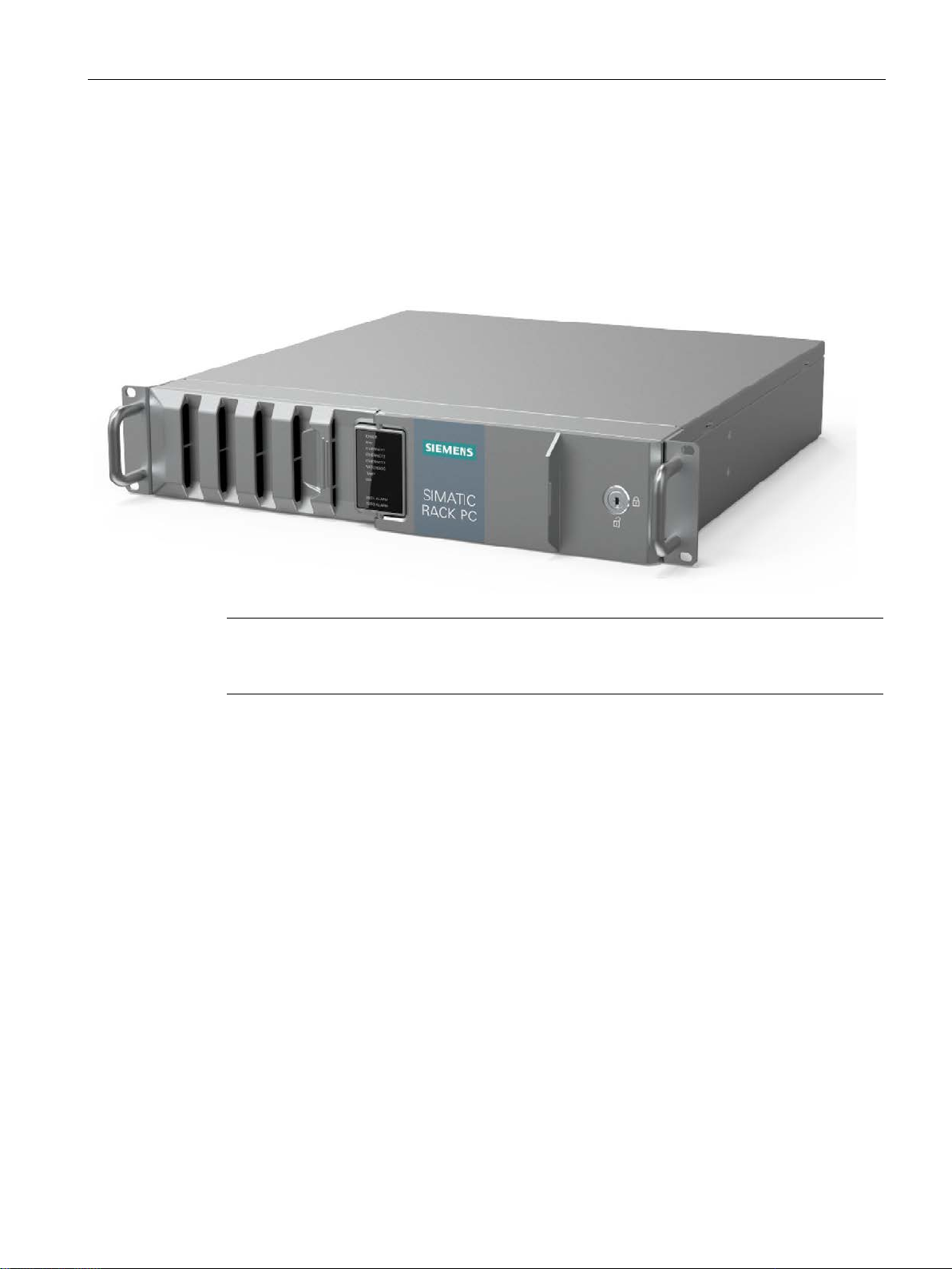
1.2 Product highlights
1.2 Product highlights
The SIMATIC IPC647E is a high-performance industrial PC in 19" installation format (2 U). It
is perfectly suited for PC applications with high-level industry functionality.
Device view
ce.
Maximum industrial compatiblity for 24-hour continuous use in industrial environments
● Maximum processor performance (in full version) without loss of performance (throttling)
at up to 50° C ambient temperature
● Fully coated surfaces that repel dirt and corrosion
● Rugged all-metal enclosure, fully coated (blue-chromed) and painted on the outside to
protect from corrosion and dirt with high EMC
● Suitable for installation in space-saving switchgear cabinet measuring only 500 m in
depth
● Dust protection through overpressure venting concept with front-side fan and dust filter
● Protection against vibration and shock through corresponding hard drive retainer and
card hold-down mechanism
SIMATIC IPC647E
Operating Instructions, 11/2018, A5E45589180-AA
13

Product description
1.2 Product highlights
High productivity through fast data processing
● 8th generation Intel® processors: Xeon, Core i7, Core i5 or Core i3 with up to 6 cores / 12
threads
● Graphics controller (630/P630) integrated in the processor up to 4 K Ultra HD resolution
● Maximum performance, e.g. through Intel C246 chipset, DDR4 memory with support of
dual channel technology
● High data transfer rates, e.g. via PCI Express Technology Gen 3, USB 3.1 Gen 2
SuperSpeed + (10 Gbps), M.2 NVME SSD
● Low noise impact thanks to closed-loop fan
High system availability thanks to minimization of standstill times (availability depending on
configuration)
● High data security through RAID systems: Onboard RAID system or hardware RAID
system
● RAID1 system: Data mirroring on two SATA or SAS drives, including in removable racks,
and optionally with additional SSD (for operating system)
● Hot swap (swapping of drive during operation) in removable drive bays in RAID systems
● Fast identification and swapping of drives under error conditions through alarm LEDs for
RAID systems
● Efficient event diagnostics through the SIMATIC IPC DiagBase or DiagMonitor monitoring
software (optional)
● Remote control and remote maintenance of the device through iAMT (Intel® Active
Management Technology)
● SSD as 2.5" SATA or M.2 NVMe and ECC memory (optional)
● Replacement of power supply module for redundant power supply in runtime
Differentiated safety concepts
● Lockable front door for component protection against unauthorized access, e.g.
– Software dongle in USB connection behind the front door
– Front fan can only be replaced when front door is open
– All components inside the device can only be accessed when front door is open
● Device monitoring through operating displays on the front for Ethernet; alarms for fans,
temperature, Watchdog and drives in RAID1 systems
SIMATIC IPC647E
14 Operating Instructions, 11/2018, A5E45589180-AA

Product description
1.3 Scope of application
High investment protection
● Platform with embedded Intel components for long-term stability
● Availability: 3 to 6 years
● Assured spare parts availability: 5 years after product phase-out
● Certified for worldwide marketing (cULus)
● Support of legacy interfaces (COM)
● Compatible installation across device generations
● Worldwide service and support
User-friendly application scenarios for commissioning, use and service
● High flexibility and expandability thanks to integrated interfaces and up to 4 slots (PCI and
PCI Express)
● Pre-installed and activated operating system
● Fast restoration of delivery state of the operating system (with supplied data storage
medium)
● Universal use as industrial workstation or industrial server
● Gbit LAN with teaming capability (3 x LAN 10/100/1000 Mbps connections)
● Service-friendly device configuration (modifications, service), e.g. replacement of filter or
front fan without tools
● Flexible usage options with telescopic rails
1.3 Scope of application
The SIMATIC IPC offers system integrators, cabinet designers, system engineers and
machine designers a 19" rack PC platform for high-performance applications and IT
applications on the control and cell level for:
● Process and visualization applications
● Industrial image processing
● Quality assurance and monitoring tasks
● Measurement, control and rule-based tasks
● Data acquisition and management
The SIMATIC IPC has CE certification for use in the industrial sector as well as in residential
and commercial areas and small businesses. In addition to the industrial applications,
therefore, it can also be used in building automation or in public facilities.
SIMATIC IPC647E
Operating Instructions, 11/2018, A5E45589180-AA
15
Product description
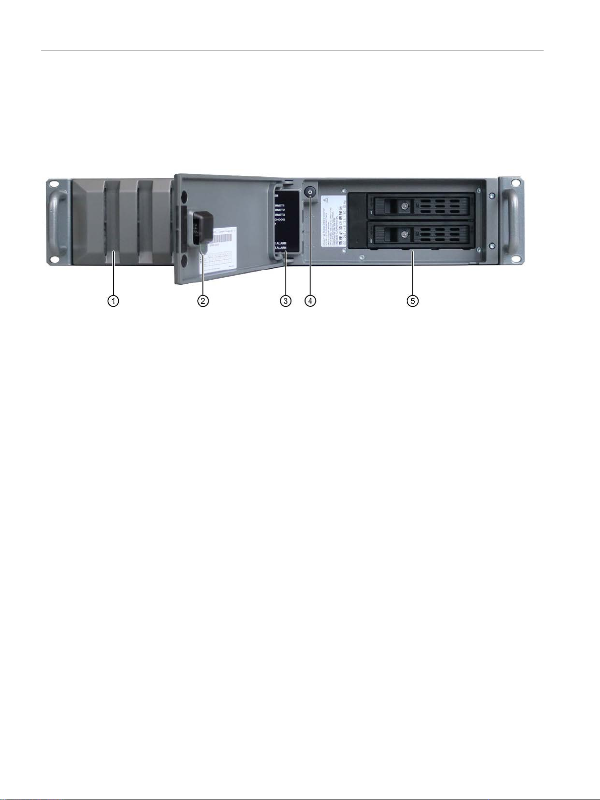
①
Fan cover on front fan with openings to ventilate the device (locked with front door)
②
Front door: lockable, protection against unauthorized access
Lock
•
•
③
System status displays
④
On
⑤
Mounting spaces for drives
1.4 External design of the device
1.4 External design of the device
1.4.1 Front panel
See also
Key vertical: open
Key horizontal: closed
-off button
Interfaces (Page 20)
Operator controls (Page 22)
(Page 24)
SIMATIC IPC647E
16 Operating Instructions, 11/2018, A5E45589180-AA
Product description
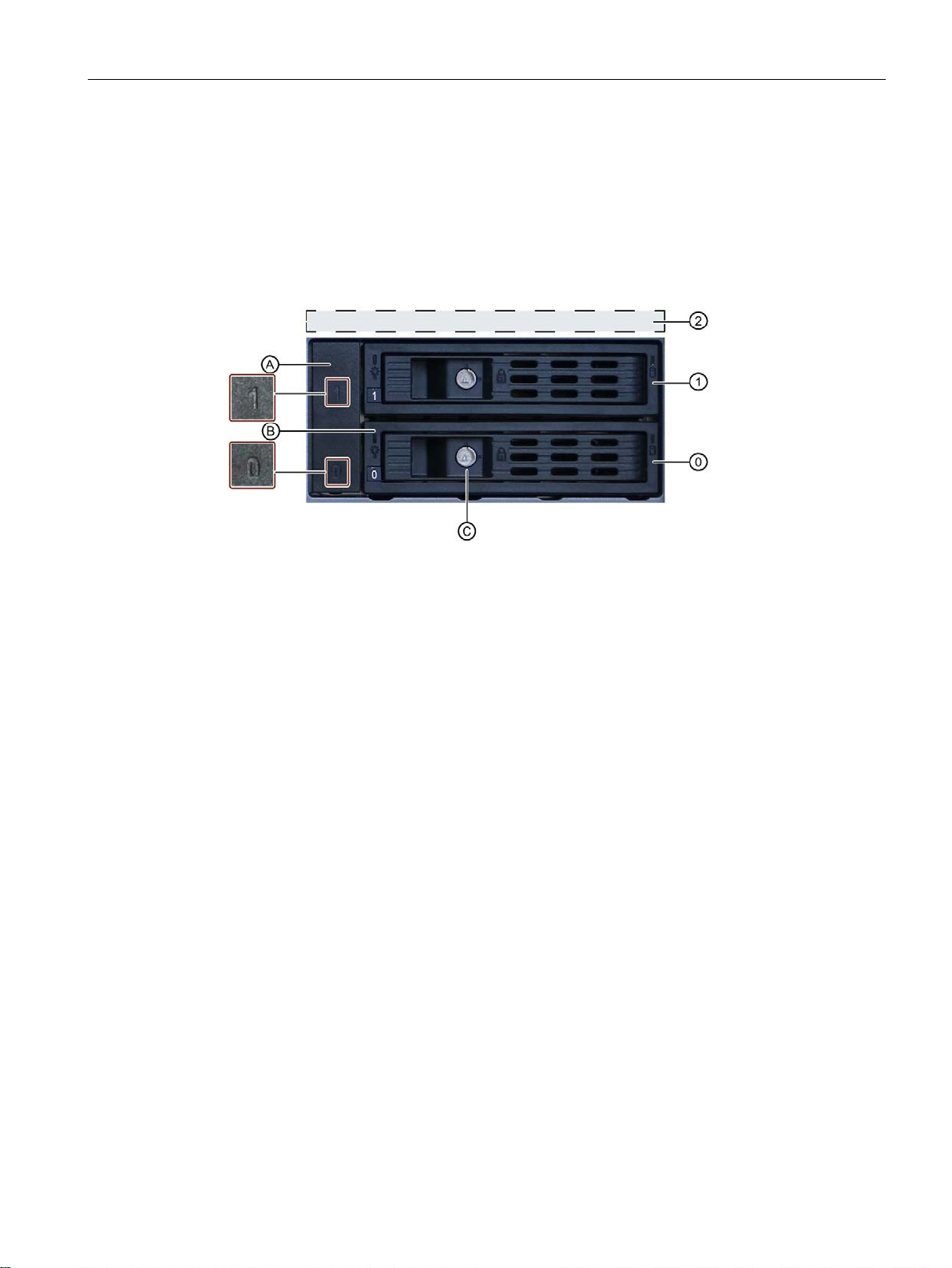
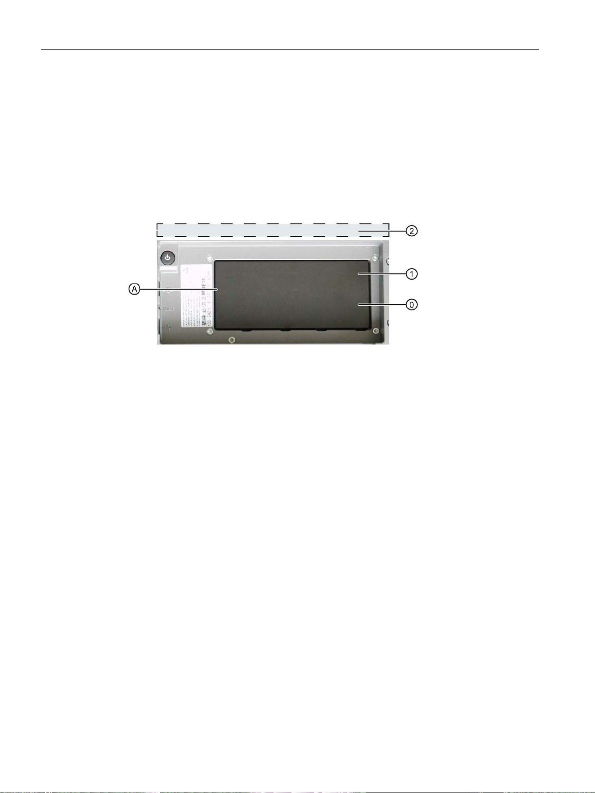
(
Mounting location 0
Mounting space for 3.5" or 2.5" drive in removable tray
(1) Mounting location 1
Mounting space for 3.5" or 2.5" drive in removable tray
(2) Mounting location internally
Mounting space for 2.5" drive internally (see
A (Page 101))
(A)
Blanking plate
(B)
Removable tray
(C)
Removable tray lock
1.4 External design of the device
1.4.2 Drive cage type A
The drive cage type A is located behind the front door.
Drives can be installed here in removable trays and are therefore easily accessible from the
outside, without opening the device.
The removable trays can be locked; this way, the drives are protected from unauthorized
access.
Mounting locations
0)
Components
Additional information
Technical notes and information on the conditions of usage are available in the section
Drives in drive cage type A (Page 101).
Drives in drive cage type
SIMATIC IPC647E
Operating Instructions, 11/2018, A5E45589180-AA
17
Product description
(0)
Mounting location 0
Mounting space for 3.5" drive in a shock/vibration-damped system
(1)
Mounting location 1
Mounting space for 3.5" drive in a shock/vibration-damped system
(2)
Mounting location
internally
Mounting space for 2 x 2.5" drive internally (see
type B (Page 110))
(A)
Cover
1.4 External design of the device
1.4.3 Drive cage type B
The drive cage type B is located behind the front door.
In drive cage type B, drives are permanently installed inside and cannot be accessed
externally.
The drives are particularly well protected in the drive cage against vibrations ("vibrationdampened drive cage").
Changing the drives for maintenance purposes can be done through the front opening after
the front panel has been unlatched.
Drive bays
Components
Additional information
Technical notes and information on the conditions of usage are available in the section
Drives in drive cage type B (Page 110).
Drives in drive cage
SIMATIC IPC647E
18 Operating Instructions, 11/2018, A5E45589180-AA
Product description
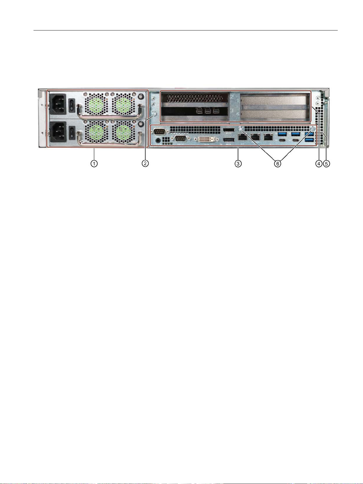
①
Power supply connections
②
Connection for functional earthing, see "
(Page 48)"
③
Interfaces
④
Expansion card slots on the bus board
⑤
Air outlet
⑥
Fixing screws for strain relief
1.4 External design of the device
1.4.4 Rear of the device
Device with redundant AC power supply
(Page 21)
(Page 20)
Connection of equipotential bonding line
(Page 173)
SIMATIC IPC647E
Operating Instructions, 11/2018, A5E45589180-AA
19
Product description
Note
Yo
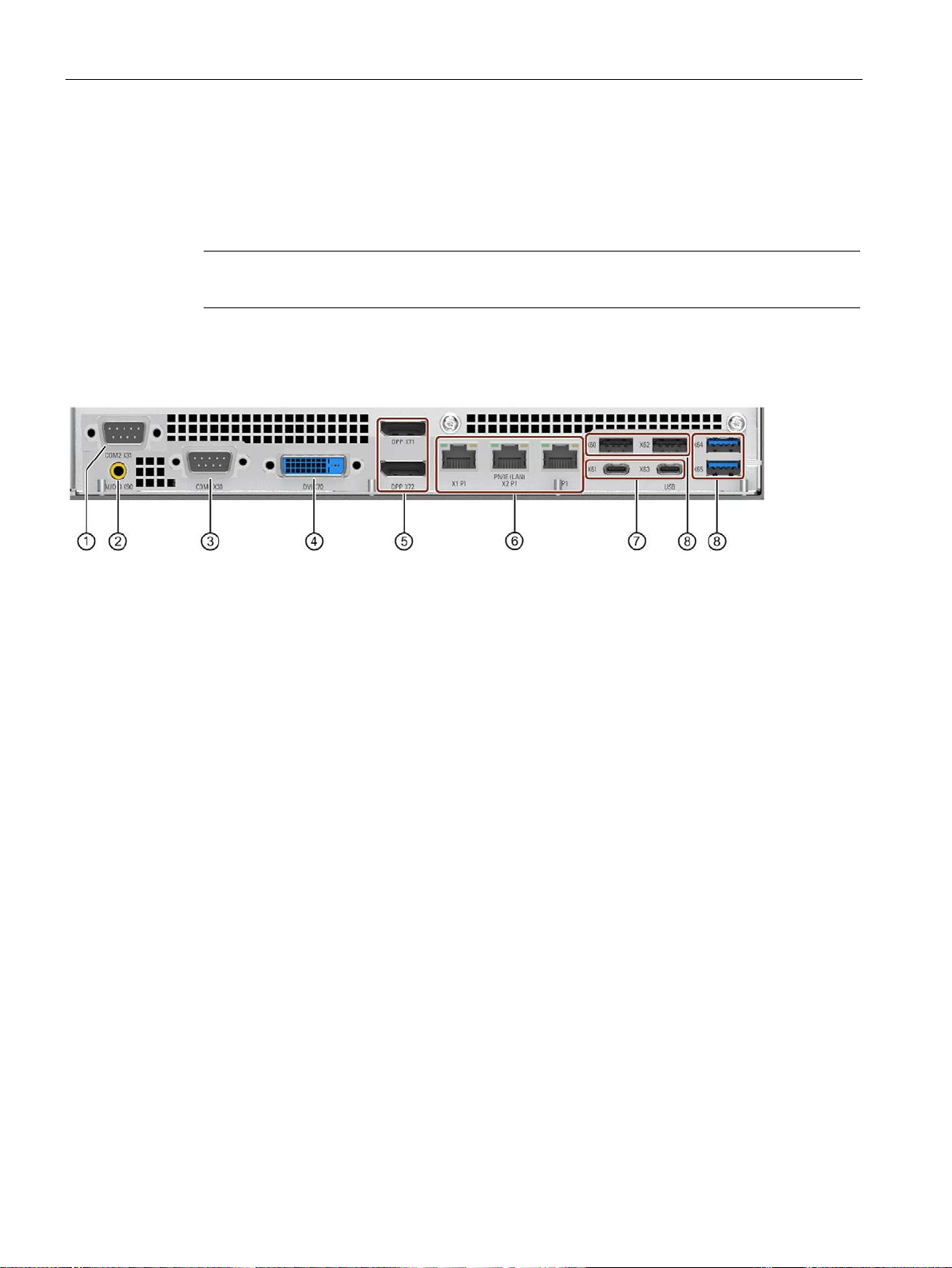
①
COM2 X31
(optional)
Serial port 2 (V.24), 9-pin SUB-D socket (optional)
②
Audio X90
UAJ connector for audio devices, 2.5 mm jack socket
③
CCOM1 X30
Serial port 1 (V.24), 9-pin SUB-D socket
④
DVI X70
Connection for monitor with DVI-D interface
⑤
2 x DPP X71/X72
Connections for DisplayPort:
•
•
er, see
•
I adapter,
see Hardware accessories (Page 29)
⑥
3 x Ethernet
X1P1/X2P1/X3P1
Connections for Ethernet RJ45 for 10/100/1000 Mbps,
Ethernet
Ethernet ports are numbered on the enclosure. The numbering by
the operating system may differ from this.
⑦
2 x USB
X61/X63
USB 3.1 GEN 2 Type C high current, backward compatible with
USB 3.0/2.0/1.1
⑧
2 x 2 USB
X60/X62/X64/X65
USB 3.1 GEN 2 Typ A high current, backward compatible with
USB 3.0/2.0/1.1
1.4 External design of the device
1.4.5 Interfaces and connections
1.4.5.1 Interfaces
u can find detailed information on interfaces under "External interfaces (Page 178)".
Interfaces at rear of device
Connection for monitors with DisplayPort
Connector for monitor with VGA interface via DP/VGA adapt-
Hardware accessories (Page 29)
Connector for monitors with DVI interface via DP/DP
X1P1 is iAMT-capable
SIMATIC IPC647E
20 Operating Instructions, 11/2018, A5E45589180-AA
Product description
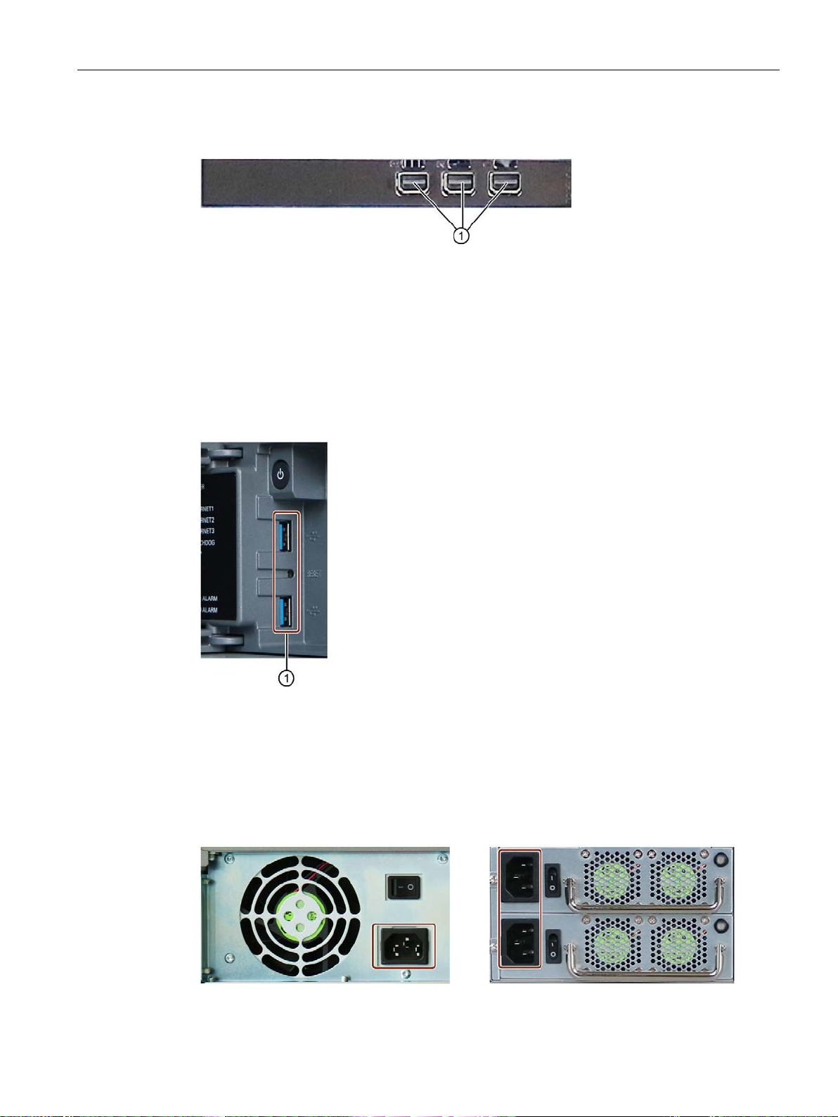
①
3 x Mini Display Port
①
USB 3.0/2.0/1.1
Socket for power plug
Simple power supply
Sockets for power plug
Redundant power supply
1.4 External design of the device
Interfaces on the optional graphics card
You can find information on the optional graphics card under "Technical specifications of
graphic (Page 151)".
Further connection options for monitors to this interface:
● Hardware accessories (Page 29)
Interfaces at front of device
The interfaces at the front of device are located behind the front door.
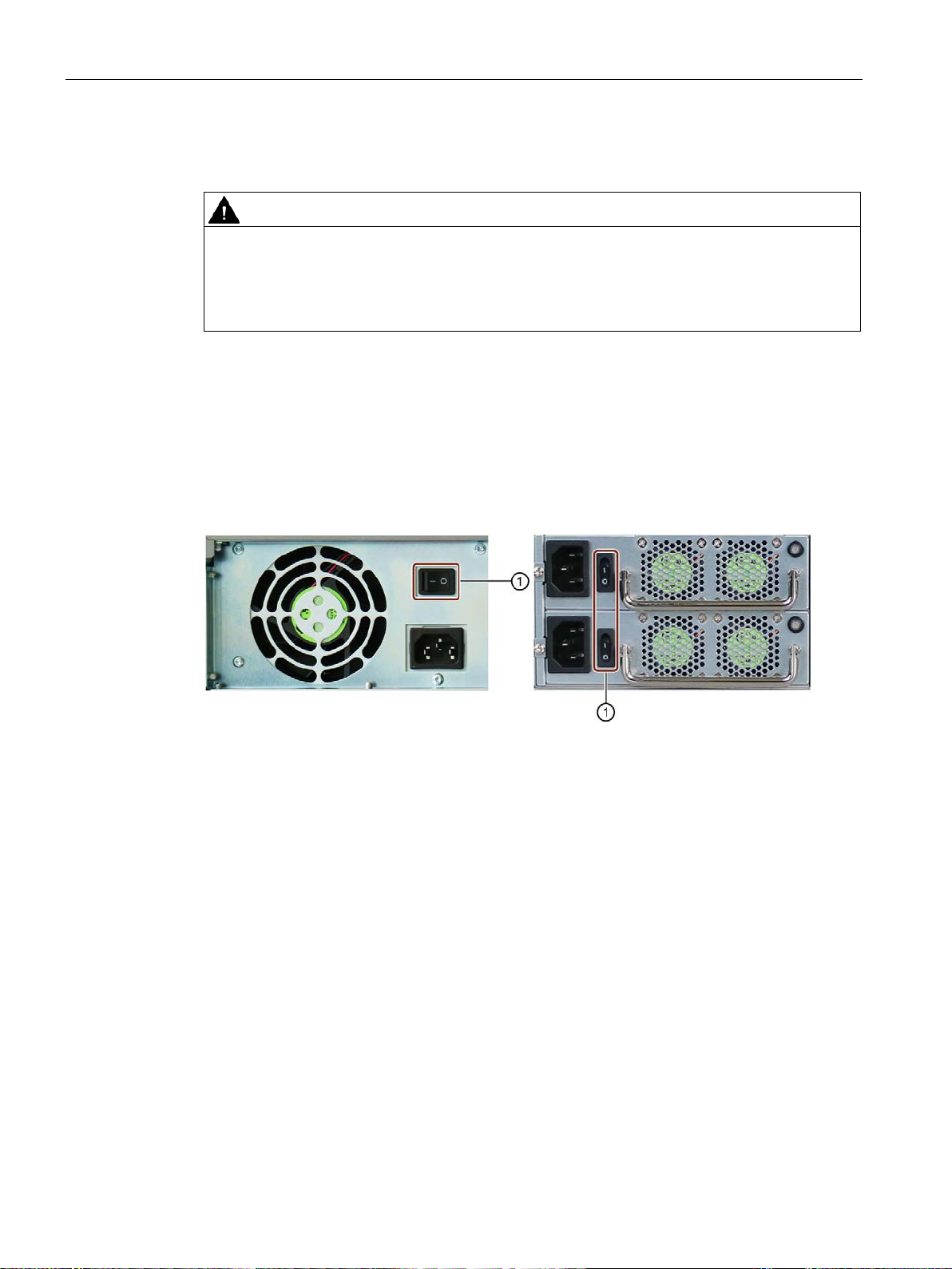
1.4.5.2 Power supply connections
SIMATIC IPC647E
Operating Instructions, 11/2018, A5E45589180-AA
2 × USB 3.1 Gen 1 Connectors for USB devices, backwards compatible with
21
Product description
WARNING
Risk of electric shock
On/Off switch
Single power supply
On/Off switch
Redundant power supply
①
On/Off switch
1.4 External design of the device
1.4.6 Operator controls
The buttons and switches described in the following do not fully disconnect the device from
the line voltage.
You also need to the notes and information under "Switching off the device (Page 58)".
On/Off switch
The following figures show the location of the on/off switch on the rear of the device for
devices with simple or redundant power supply.
SIMATIC IPC647E
22 Operating Instructions, 11/2018, A5E45589180-AA
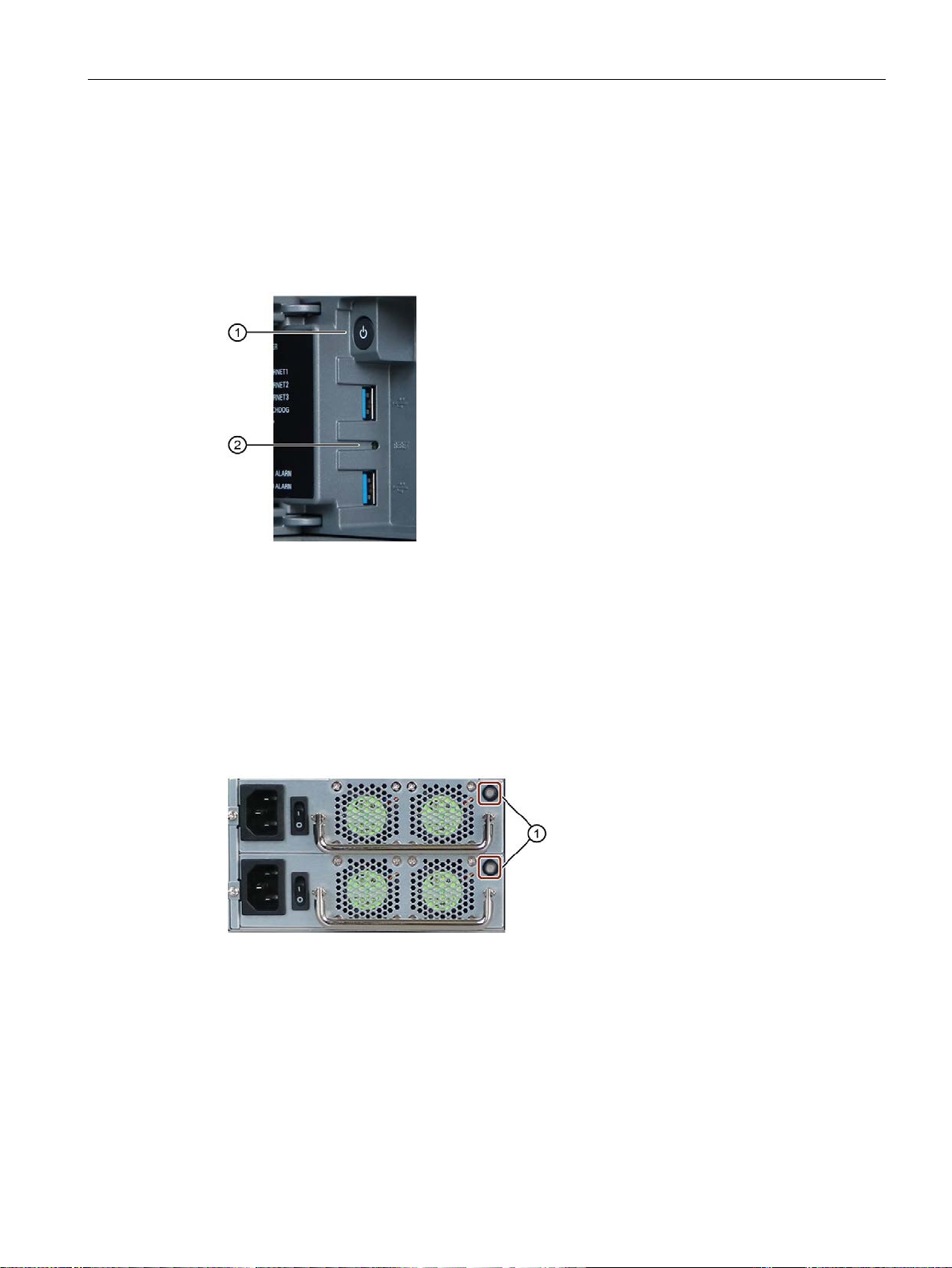
Product description
①
On/off button
②
Reset button for emergencies
①
Alarm reset button
1.4 External design of the device
On/off switch and reset button
The On/off button ① and the reset button ② are located on the front of the device behind
the front door. The On/off button starts and shuts down the operating system. The reset
button is for the emergency when the device can no longer be operated.
Additional information is available in "Switching on the device (Page 57)" and "Switching off
the device (Page 58)".
Alarm reset button (redundant power supply)
The alarm reset button is only available for devices with redundant power supply.
Use the alarm reset button to switch off the signal tone of the redundant power supply in the
event of an error.
SIMATIC IPC647E
Operating Instructions, 11/2018, A5E45589180-AA
23
Product description
Item
Status display
Meaning
Color
Description
①
mains
YELLOW
Idle state or shut down
GREEN
PC in operation
OFF
No access
GREEN
Access
⑤
OFF
Not activated
GREEN
Activated
RED
Expired
⑦
OFF
No error
⑧
OFF
No error
1.4 External design of the device
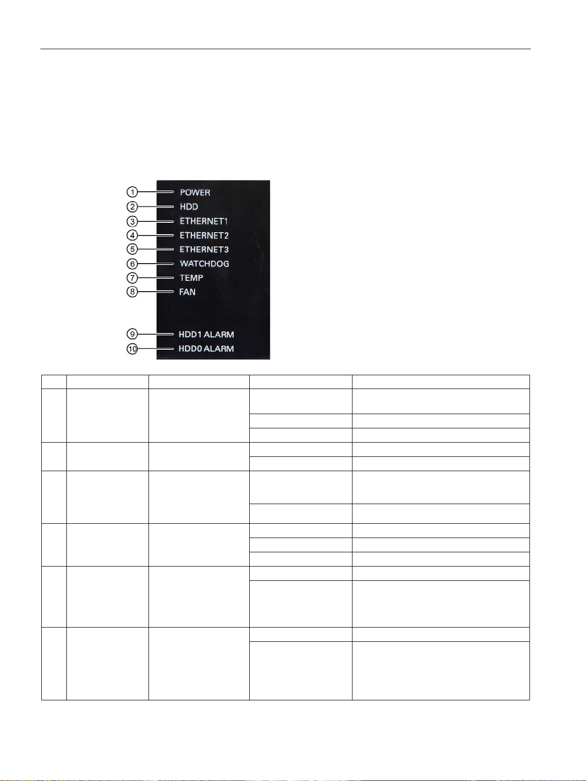
1.4.7 Status displays
1.4.7.1 System status displays
The status displays for the system are located on the front of the device. They provide
information on the status of the device components.
POWER Operating mode of the
HDD Access to hard disk
②
ETHERNET 1
③
ETHERNET 2
④
ETHERNET 3
WATCHDOG Watchdog status
⑥
TEMP
FAN Fan status
PC
Ethernet status display OFF
Temperature status
OFF Switched off or disconnected from the
• No connection
• No data traffic
GREEN Data traffic
RED Possible causes:
• CPU temperature is critical
• Device temperature is critical
RED Possible causes:
• Front fan faulty
• Fan of simple power supply faulty (non-
redundant power supply)
SIMATIC IPC647E
24 Operating Instructions, 11/2018, A5E45589180-AA

Product description
Item
Status display
Meaning
Color
Description
OFF
RAID is OK
A RED LED is lit up
The associated drive is not OK
disk.
system (Page 62)".
1.4 External design of the device
HDD1 ALARM
⑨
HDD0 ALARM
⑩
HDD alarm in combination with RAID and
monitoring software.
The number of the HDD
alarm corresponds to
the number of mounting
locations of drives, see
"Drive cage type A
(Page 17)" and "Drive
cage type B (Page 18)".
All RED LEDs are flashing
All RED LEDs are lit up RAID is not OK
RAID synchronization running, RAID is not
OK
The hard disk newly integrated in case of
error is synchronized with an existing hard
The faulty drive could not be localized by
the monitoring software. It may be possible
to detect the defective drive with the RAID
software.
You can find information under "RAID1
SIMATIC IPC647E
Operating Instructions, 11/2018, A5E45589180-AA
25
Product description
Status display
Meaning
Status
Meaning of the status
Status display
Meaning
Status
Meaning of the status
1.4 External design of the device
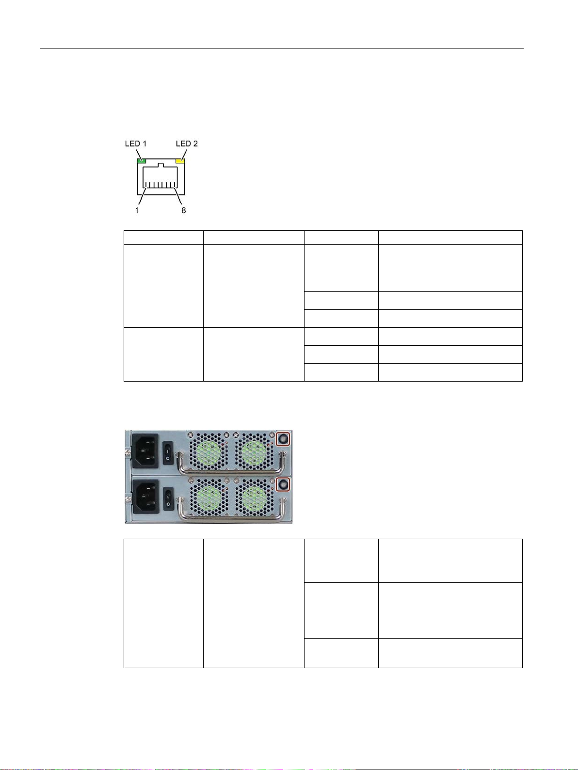
1.4.7.2 Status display of the Ethernet interface
The Ethernet interfaces are numbered on the enclosure to identify them clearly.
The numbering by the operating system can differ.
LED 1 Connection status OFF
LED 2 Data transmission rate OFF
1.4.7.3 Status display of redundant power supply
GREEN
GREEN flashing
GREEN
YELLOW
• No cable connected
• Cable disabled
• Interface disabled
• Active cable connected
• Data transfer active
• 10 Mbps
• 100 Mbps
• 1000 Mbps
SIMATIC IPC647E
26 Operating Instructions, 11/2018, A5E45589180-AA
Status LED (see
marking)
Status of the power
supply module
OFF
GREEN
RED
• Module is out of service, no
redundancy in effect.
• The module is in operation and
functioning.
• Redundancy is in effect when
both modules are operating.
• Module failed, no redundancy
in effect.
Product description
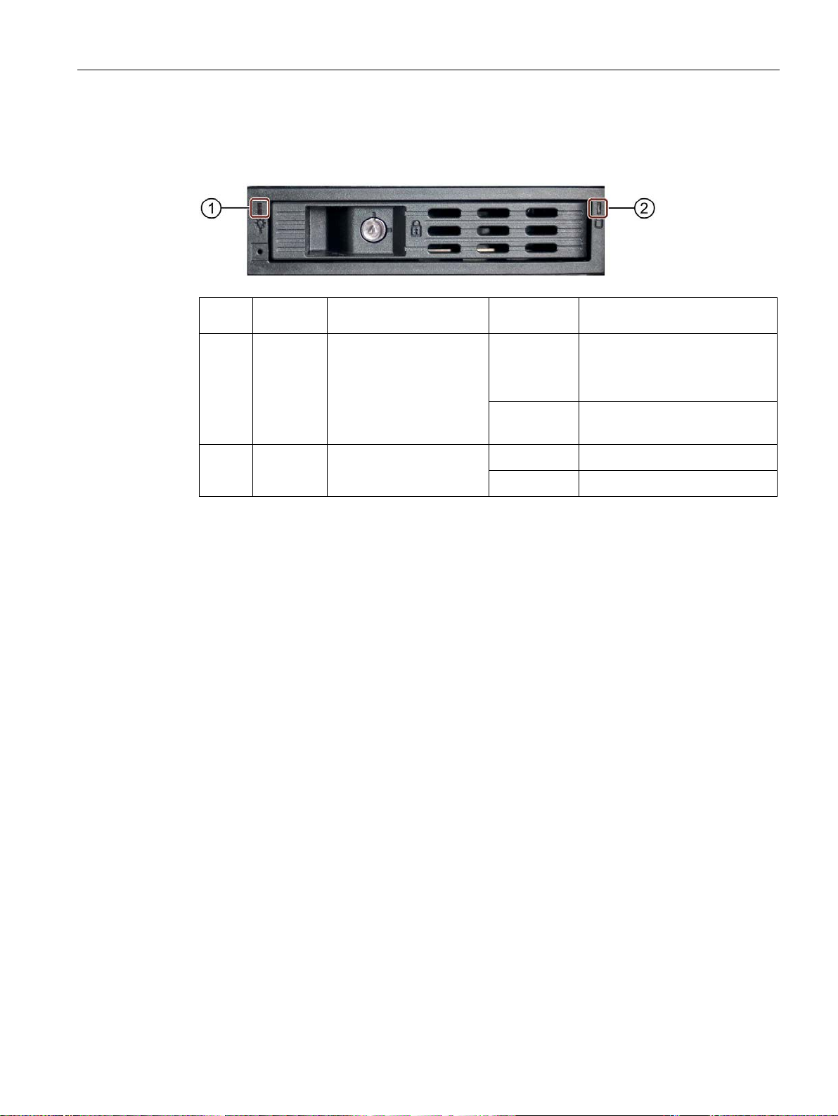
Item Status
display
Meaning
Status
Meaning of the status
1.4 External design of the device
1.4.7.4 Status displays on removable tray for drives
①
②
Power Status of the removable
tray
Activity Status of the drive Flashes
OFF
Lit
OFF
• Device switched off
• Power supply not connected
• No drive installed
• Device is switched on and a
drive is installed
• Drive is active
• Drive is not active
SIMATIC IPC647E
Operating Instructions, 11/2018, A5E45589180-AA
27
Product description
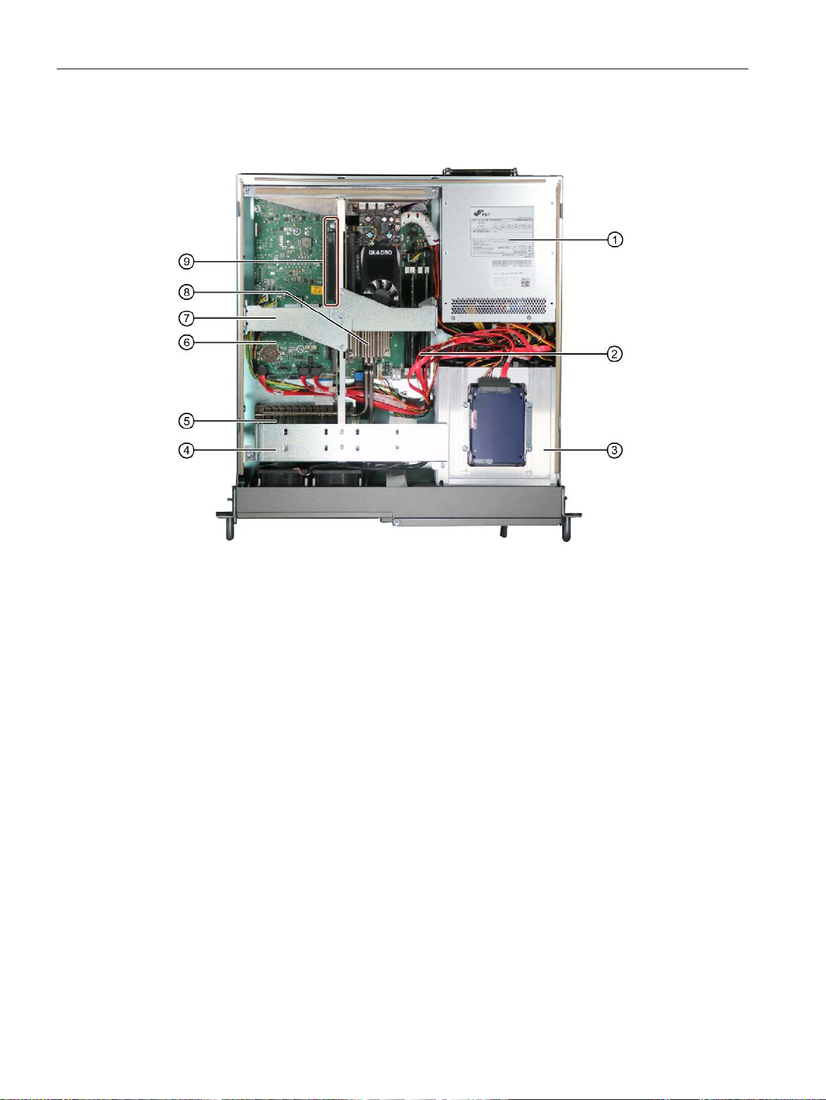
①
Power supply, single or redundant
②
4 x memory module slots
③
Drive cage
④
Guide rail for long expansion cards
⑤
Heat sink; connected to heat transport via 2 heat pipes with heat sink of the processor ⑦
⑥
Motherboard
⑦
Retainer for expansion modules
⑧
Heat exchanger of the processor
⑨
Bus board with expansion card slots
1.5 Internal construction of the device
1.5 Internal construction of the device
SIMATIC IPC647E
28 Operating Instructions, 11/2018, A5E45589180-AA
Product description
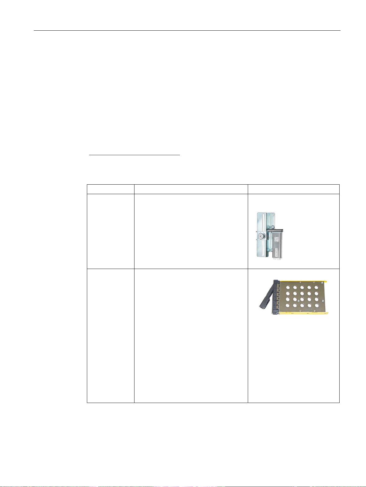
Name
Description
Article number
1.6 Accessories and spare parts
1.6 Accessories and spare parts
1.6.1 Hardware accessories
Accessories from Siemens are available for your device that are not included in the scope of
delivery.
Obtaining accessories from the SIEMENS Industry Mall
You can find more information in the online ordering system Industry Mall
(https://mall.industry.siemens.com).
Accessories available for order
Retainer for
locking the internal USB interface
Low profile removable rack
unit
The retainer is a mechanical safety device
for the internal USB interface. It optimizes
the protection of an internal USB memory
stick against loads caused by vibration and
shock during transportation or operation.
This increases the reliability and operational
safety of the device.
The removable tray makes for quick and
simple replacement of a 2.5" or 3.5" drive
without having to open the device or remove
it from the control cabinet. The result is the
following advantages for service and
maintenance, data backup and data transfer:
• Replacement of a failed hard disk in
operation ("hot-swap")
• Downloading different system states or
operating systems from different hard
drives during a short period of time.
• Simplified data backup by copying, for
example, to a backup hard drive.
• Simple transportation of backup data
• Separate data storage and archiving
possible
6ES7648-1AA00-0XK0
6ES7648-0EH00-1BA0
SIMATIC IPC647E
Operating Instructions, 11/2018, A5E45589180-AA
29
Product description
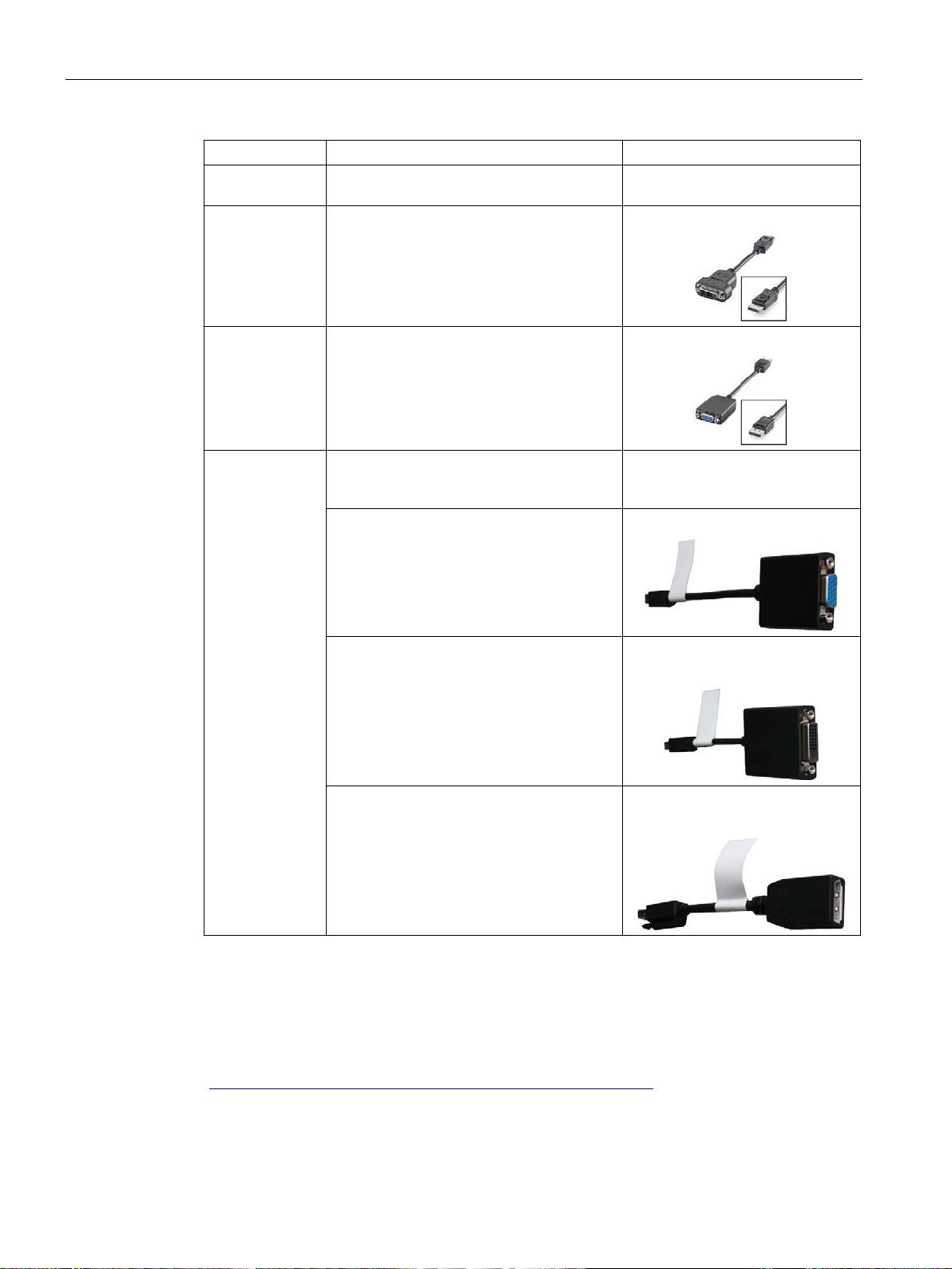
Name
Description
Article number
pack of 10 filter mats
following adapters:
* Part of the optional graphics card
1.6 Accessories and spare parts
Filter mat Filter mat for fan cover on front of device,
DP to DVI-D
adapter
DP / VGA adapter
mDP adapter
Graphics adapter cable, DisplayPort to DVI 6ES7648-3AF00-0XA0
Graphics adapter cable, DisplayPort to VGA 6ES7648-3AG00-0XA0
Connection of dual-head adapter to the
optional graphics card possible with the
• mDP VGA adapter
Mini DisplayPort according to VGA
A5E37019277
1 unit 6ES7648-3AL00-0XA0
SIEMENS spare parts services
Information on ordering, the provision and delivery of spare parts can be found under
"Industry Online Support: Spare parts services
(http://support.automation.siemens.com/WW/view/en/16611927)".
• mDP-DVI-D adapter
Mini DisplayPort to DVI, available as
single-pack or 3-pack
• mDP-DP adapter *
Mini DisplayPort to DisplayPort, available as single-pack or 3-pack
1 unit 6ES7648-3AK00-0XA0
3 units 6ES7648-3AK00-1XA0
1 unit 6ES7648-3AJ00-0XA0
3 units 6ES7648-3AJ00-1XA0
SIMATIC IPC647E
30 Operating Instructions, 11/2018, A5E45589180-AA
 Loading...