

Siemens SIMATIC IPC627D, SIMATIC IPC827D Operating Instructions Manual

SIMATIC IPC627D/827D
___________________
___________________
___________________
___________________
___________________
___________________
___________________
___________________
___________________
___________________
___________________
SIMATIC
Industrial PC
SIMATIC IPC627D/827D
Operating Instructions
09/2014
A5E32990859
Preface
Overview
1
Safety Instructions
2
Installing and connecting the
device
3
Commissioning the device
4
Extended device functions
5
Expanding and assigning
parameters to the device
6
Device maintenance and
repair
7
Technical specifications
8
Technical support
A
Abbreviations
B
-AB

Siemens AG
Industry Sector
Postfach 48 48
90026 NÜRNBERG
GERMANY
A5E32990859-AB
Ⓟ
Copyright © Siemens AG 2014.
All rights reserved
Legal information
Warning notice system
DANGER
indicates that death or severe personal injury will result if proper precautions are not taken.
WARNING
indicates that death or severe personal injury may result if proper precautions are not taken.
CAUTION
indicates that minor personal injury can result if proper precautions are not taken.
NOTICE
indicates that property damage can result if proper precautions are not taken.
Qualified Personnel
personnel qualified
Proper use of Siemens products
WARNING
Siemens products may only be used for the applications described in the catalog and in the relevant technical
maintenance are required to ensure that the products operate safely and without any problems. The permissible
ambient conditions must be complied with. The information in the relevant documentation must be observed.
Trademarks
Disclaimer of Liability
This manual contains notices you have to observe in order to ensure your personal safety, as well as to prevent
damage to property. The notices referring to your personal safety are highlighted in the manual by a safety alert
symbol, notices referring only to property damage have no safety alert symbol. These notices shown below are
graded according to the degree of danger.
If more than one degree of danger is present, the warning notice representing the highest degree of danger will
be used. A notice warning of injury to persons with a safety alert symbol may also include a warning relating to
property damage.
The product/system described in this documentation may be operated only by
task in accordance with the relevant documentation, in particular its warning notices and safety instructions.
Qualified personnel are those who, based on their training and experience, are capable of identifying risks and
avoiding potential hazards when working with these products/systems.
Note the following:
documentation. If products and components from other manufacturers are used, these must be recommended
or approved by Siemens. Proper transport, storage, installation, assembly, commissioning, operation and
All names identified by ® are registered trademarks of Siemens AG. The remaining trademarks in this publication
may be trademarks whose use by third parties for their own purposes could violate the rights of the owner.
We have reviewed the contents of this publication to ensure consistency with the hardware and software
described. Since variance cannot be precluded entirely, we cannot guarantee full consistency. However, the
information in this publication is reviewed regularly and any necessary corrections are included in subsequent
editions.
for the specific
09/2014 Subject to change

Preface
Purpose of the Operating Instructions
Basic knowledge required
Scope of the operating instructions
Approbations
CE marking
Standards
Position in the information landscape
These operating instructions contain all the information you need to commission and operate
the SIMATIC IPC627D and IPC827D.
It is intended both for programming and testing personnel who commission the device and
connect it with other units (automation systems, programming devices), as well as for service
and maintenance personnel who install add-ons or carry out fault/error analyses.
A solid background in personal computers and Microsoft operating systems is required to
understand this manual. General knowledge in the field automation control engineering is
recommended.
These operating instructions are valid for all versions of the SIMATIC IPC627D and
IPC827D.
You will find additional information in "Certificates and approvals (Page 101)".
You will find additional information in "Certificates and approvals (Page 101)".
For more information, refer to chapters "Certificates and approvals (Page 101)" and
"Technical specifications (Page 113)".
The IPC documentation comprises:
● SIMATIC IPC627D operating instructions
SIMATIC IPC627D/827D
Operating Instructions, 09/2014, A5E32990859-AB
● SIMATIC IPC827D operating instructions
The documentation is supplied with the IPC in German and English in electronic form as a
PDF file on the "Documentation and Drivers" CD/DVD.
3

Preface
Conventions
Note
A note is important information about the product, handling the product or a reference to
specific sections of the documentation that require special consideration.
History
Edition
Comment
12/2013
First edition
09/2014
Revision: HDD in removable drive bay and RAID
The terms "PC" and "device" are sometimes used to refer to the SIMATIC IPC627D and
SIMATIC IPC827D in this documentation.
The term "Windows Embedded Standard" is used throughout to refer to "Windows
Embedded Standard 7 Professional (WES 7/P)". "Windows 7" is used as an abbreviation for
"Windows 7 Ultimate".
The following editions of these operating instructions have already been published:
SIMATIC IPC627D/827D
4 Operating Instructions, 09/2014, A5E32990859-AB

Table of contents
Preface ................................................................................................................................................... 3
1 Overview................................................................................................................................................. 9
2 Safety Instructions ................................................................................................................................ 19
3 Installing and connecting the device ...................................................................................................... 23
4 Commissioning the device .................................................................................................................... 43
1.1 Product description ................................................................................................................... 9
1.1.1 Applications ............................................................................................................................... 9
1.1.2 Features .................................................................................................................................. 10
1.2 Design of the device ............................................................................................................... 13
1.2.1 Operator controls and interfaces ............................................................................................ 13
1.2.2 Status displays ........................................................................................................................ 15
1.2.3 Removable drive bay status displays ..................................................................................... 17
2.1 General safety instructions ..................................................................................................... 19
2.2 Notes on use ........................................................................................................................... 22
3.1 Preparing for installation ......................................................................................................... 23
3.1.1 Checking the delivery package ............................................................................................... 23
3.1.2 Identification data of the device .............................................................................................. 25
3.1.3 Permitted mounting positions ................................................................................................. 26
3.2 Installing the device ................................................................................................................ 28
3.2.1 Installation guidelines.............................................................................................................. 28
3.2.2 Mounting instructions .............................................................................................................. 28
3.2.3 Installing the device with mounting brackets .......................................................................... 29
3.2.4 Installing the device with the vertical mounting kit .................................................................. 31
3.2.5 Installing the device with the vertical mounting kit for PC port access from the front ............ 32
3.3 Connecting the device ............................................................................................................ 33
3.3.1 Wiring information ................................................................................................................... 33
3.3.2 Connecting the Equipotential Bonding Circuit ........................................................................ 34
3.3.3 Connecting 100-240 VAC power supply ................................................................................. 35
3.3.4 Connecting the 24 VDC power supply .................................................................................... 37
3.3.5 Connecting peripheral equipment ........................................................................................... 38
3.3.6 Connecting the device to networks ......................................................................................... 39
3.3.7 PROFINET .............................................................................................................................. 40
3.3.8 Connecting Ethernet/USB strain relief .................................................................................... 41
3.3.9 Connecting the PROFINET strain relief .................................................................................. 42
4.1 General information on commissioning .................................................................................. 43
4.2 Switching on the device .......................................................................................................... 44
4.3 Automatic switching on of the device ...................................................................................... 45
4.4 Windows Action Center........................................................................................................... 45
SIMATIC IPC627D/827D
Operating Instructions, 09/2014, A5E32990859-AB
5

Table of contents
5 Extended device functions .................................................................................................................... 49
6 Expanding and assigning parameters to the device ............................................................................... 59
7 Device maintenance and repair ............................................................................................................. 73
4.5 Notes on different device configurations ................................................................................ 46
4.5.1 Notes on the DVD burner ....................................................................................................... 46
4.5.2 RAID1 system ........................................................................................................................ 46
4.5.3 Replacing hard disks .............................................................................................................. 47
4.6 Switching off the device ......................................................................................................... 48
5.1 Monitoring Functions .............................................................................................................. 49
5.1.1 Overview of the monitoring functions ..................................................................................... 49
5.1.2 Temperature monitoring/display ............................................................................................ 50
5.1.3 Watchdog (WD)...................................................................................................................... 50
5.1.4 Battery monitoring .................................................................................................................. 51
5.2 Enhanced Write Filter (EWF) ................................................................................................. 51
5.3 File Based Write Filter (FBWF) .............................................................................................. 54
5.4 SRAM buffer memory (optional) ............................................................................................ 55
5.5 Operation without monitor and keyboard ............................................................................... 56
5.6 Active Management Technology (AMT) ................................................................................ 56
5.7 Trusted Platform Modul (TPM) ............................................................................................... 57
6.1 Opening the Device ............................................................................................................... 59
6.2 Memory expansion ................................................................................................................. 60
6.3 Expansion cards..................................................................................................................... 62
6.3.1 Notes on the expansion cards ............................................................................................... 62
6.3.2 Removing and installing expansion cards with 627D ............................................................ 63
6.3.3 Removing and installing expansion cards with 827D ............................................................ 64
6.4 Drives ..................................................................................................................................... 66
6.4.1 Installation options for internal drives .................................................................................... 66
6.4.2 Removing and installing the drive bay module ...................................................................... 67
6.4.3 Removing and installing hard disks ....................................................................................... 67
6.4.4 Removing and installing an SSD drive .................................................................................. 69
6.4.5 Installation options for external drives ................................................................................... 70
6.4.6 Removing and installing a DVD drive .................................................................................... 71
7.1 Maintenance ........................................................................................................................... 73
7.2 Managing RAID systems ....................................................................................................... 73
7.2.1 Example for a RAID1 system during the boot phase of the system ...................................... 73
7.2.2 RAID software ........................................................................................................................ 74
7.2.3 Checking the status of the RAID system ............................................................................... 74
7.2.4 Displaying a defective hard disk of a RAID system in the RAID software ............................. 75
7.2.5 Special feature: Replacing hard disk in the RAID system when switched off ....................... 76
7.2.6 Integrating a new hard disk drive in the RAID system ........................................................... 76
7.3 Repair and spare parts .......................................................................................................... 78
7.4 Removing and installing hardware ......................................................................................... 80
7.4.1 Replacing a defective hard disk drive in the RAID system .................................................... 80
SIMATIC IPC627D/827D
6 Operating Instructions, 09/2014, A5E32990859-AB

Table of contents
8 Technical specifications ...................................................................................................................... 101
7.4.2 Removing and installing the hard disk in the removable drive bay ........................................ 81
7.4.3 Replacing the Backup Battery ................................................................................................ 82
7.4.4 Removing and installing the power supply ............................................................................. 84
7.4.5 Removing and installing the bus board ................................................................................... 85
7.4.6 Removing and installing the power supply fan ....................................................................... 86
7.4.7 Removing and installing the device fan .................................................................................. 87
7.4.8 Replacing the processor ......................................................................................................... 89
7.5 Installing the software ............................................................................................................. 91
7.5.1 Sources for installation of the operating system ..................................................................... 91
7.5.2 Updating the operating system ............................................................................................... 91
7.5.3 Installing drivers and software ................................................................................................ 92
7.5.4 Installing Windows 7 ............................................................................................................... 92
7.5.5 Setting up the language selection by means of the Multilanguage User Interface (MUI) ...... 96
7.5.6 Recovery DVD languages ...................................................................................................... 98
7.5.7 Installing the RAID controller software .................................................................................... 98
7.5.8 Update installation .................................................................................................................. 98
7.5.8.1 Updating the operating system ............................................................................................... 98
7.5.8.2 Installing or updating application programs and drivers ......................................................... 99
7.5.8.3 CP 1616 onboard .................................................................................................................... 99
7.5.9 Backing up data ...................................................................................................................... 99
7.5.9.1 Creating an image ................................................................................................................... 99
7.6 Recycling and disposal ........................................................................................................... 99
8.1 Certificates and approvals .................................................................................................... 101
8.2 Directives and declarations ................................................................................................... 102
8.2.1 CE marking ........................................................................................................................... 102
8.2.2 ESD guideline ....................................................................................................................... 103
8.3 Dimension drawings .............................................................................................................. 105
8.3.1 Dimension drawings of SIMATIC IPC627D .......................................................................... 105
8.3.2 Dimension drawings of SIMATIC IPC827D .......................................................................... 109
8.3.3 Dimensional drawing for the installation of expansion modules ........................................... 112
8.4 Technical specifications ........................................................................................................ 113
8.4.1 General technical specifications ........................................................................................... 113
8.4.2 Ambient conditions ................................................................................................................ 117
8.4.3 Power and energy requirements ........................................................................................... 118
8.4.4 AC voltage supply ................................................................................................................. 119
8.4.5 DC power supply ................................................................................................................... 121
8.5 Hardware descriptions .......................................................................................................... 122
8.5.1 Motherboard .......................................................................................................................... 122
8.5.1.1 Structure and functions of the motherboard ......................................................................... 122
8.5.1.2 Position of the interfaces on the motherboard ...................................................................... 123
8.5.1.3 Internal interfaces ................................................................................................................. 124
8.5.1.4 Front interfaces (only in combination with IPC677D) ........................................................... 125
8.5.2 Bus board .............................................................................................................................. 126
8.5.2.1 Layout and principle of operation .......................................................................................... 126
8.5.2.2 PCI slot pin assignment ........................................................................................................ 128
8.5.2.3 Pin assignment 12 V power supply connection for expansion cards ................................... 129
8.5.2.4 PCI Express slot x16 pin assignment ................................................................................... 130
SIMATIC IPC627D/827D
Operating Instructions, 09/2014, A5E32990859-AB
7

Table of contents
A Technical support................................................................................................................................. 165
B Abbreviations ....................................................................................................................................... 169
Glossary .............................................................................................................................................. 175
Index ................................................................................................................................................... 183
8.5.3 External ports ....................................................................................................................... 132
8.5.3.1 COM1/COM2 ....................................................................................................................... 132
8.5.3.2 DisplayPort ........................................................................................................................... 133
8.5.3.3 DVI-I ..................................................................................................................................... 134
8.5.3.4 Ethernet ................................................................................................................................ 135
8.5.3.5 USB 3.0 ................................................................................................................................ 135
8.5.3.6 PROFIBUS ........................................................................................................................... 136
8.5.3.7 PROFINET ........................................................................................................................... 136
8.5.4 System resources ................................................................................................................ 137
8.5.4.1 Currently allocated system resources .................................................................................. 137
8.5.4.2 System resources used by the BIOS/DOS .......................................................................... 137
8.5.5 CP 1616 onboard communications processor ..................................................................... 143
8.5.5.1 Properties ............................................................................................................................. 143
8.5.5.2 Typical Communication Partners ......................................................................................... 143
8.5.5.3 Firmware .............................................................................................................................. 145
8.5.5.4 Further actions in STEP 7/NCM PC..................................................................................... 147
8.6 BIOS description .................................................................................................................. 147
8.6.1 Overview .............................................................................................................................. 147
8.6.2 Opening the BIOS selection menu....................................................................................... 148
8.6.3 Configuration ........................................................................................................................ 150
8.6.4 Exit menu ............................................................................................................................. 151
8.6.5 General BIOS Setup settings ............................................................................................... 152
8.6.6 BIOS update ......................................................................................................................... 156
8.6.7 Alarm, error and system messages ..................................................................................... 157
8.7 Active Management Technology (AMT) .............................................................................. 158
8.7.1 Introduction .......................................................................................................................... 158
8.7.2 Overview of AMT.................................................................................................................. 159
8.7.3 Enabling Intel® AMT / basic configuration ........................................................................... 160
8.7.4 Resetting the Intel® AMT to the default settings and disabling AMT .................................. 161
8.7.5 Determining the network address ........................................................................................ 162
8.7.6 Forcing user consent ........................................................................................................... 162
8.8 Functional scope in Windows .............................................................................................. 163
8.8.1 Windows Embedded Standard 7 Professional .................................................................... 163
A.1 Service and support ............................................................................................................. 165
A.2 Troubleshooting ................................................................................................................... 166
A.3 Notes on the use of third-party modules .............................................................................. 168
SIMATIC IPC627D/827D
8 Operating Instructions, 09/2014, A5E32990859-AB
1
1.1
Product description
1.1.1
Applications
The SIMATIC IPC627D and IPC827D provide a high degree of industrial functionality.
● Compact design
● Expandability (expansion card slots)
● Scalability
● Level of performance
● High degree of ruggedness
SIMATIC IPC627D/827D
Operating Instructions, 09/2014, A5E32990859-AB
The device are available for industrial PC systems for high-performance and space-saving
applications in particular in the field of machine, plant and control cabinet engineering:
● Measuring and controlling process and machine data, for example, automated washing
systems, assembling machines and packaging machines
● Operating and visualization tasks, for example, information terminals and large-scale
displays in automobile manufacturing
● Data logging and processing, for example, system data logging and distributed process
control
9

Overview
1.1.2
Features
Basic data
1.1 Product description
Installation
Processor
Main memory
Possible configurations with
expansion cards
Graphics
DisplayPort resolutions depend on the graphics controller in the CPU,
• Wall mounting
• Vertical mounting
• Intel Xeon E3-1268L v3 2.3 (3.3) GHz, 4 cores, GT2, 8 MB cache,
HT
• Intel Core i3-4330TE 2.4 GHz, 2 cores, GT2, 3 MB cache, AMT
• Intel Celeron G1820TE 2.2 GHz, 2 cores, GT1, 2 MB cache
Memory expansion up to 16 GB with the following memory modules:
without ECC:
• 2 GB DDR3 SDRAM
• 4 GB DDR3 SDRAM
• 8 GB DDR3 SDRAM
with ECC:
• 4 GB DDR3 ECC
• 8 GB DDR3 ECC
• IPC627D:
– 2 × PCI Rev. 2.2
– 1 × PCI Rev. 2.2, 1 × PCIe x16 Rev. 3.0
– 1 × PCIe x4 Rev. 2.0, 1 × PCIe x16 Rev. 3.0
• IPC827D:
– 3 × PCI Rev. 2.2, 1 × PCIe x4 Rev. 2.0, 1 × PCIe x16 Rev. 3.0
• Intel® HD Graphics Controller P4600/4700 GT1/GT2
2D and 3D engine integrated in chipset
Dynamic Video Memory Technology
(occupies up to 512 MB in the main memory)
• DVI resolution of 640 × 480 pixels up to 1920 × 1200 pixels
• Graphics memory is claimed in main memory (dynamic UMA)
• Triple-head mode
which is represented by the processor:
• Celeron G1820TE: GT1 (HD Graphics),
maximum resolutions up to 2560 × 1600
• Core I3-4330TE: GT2 (HD Graphics 4600),
maximum resolutions up to 3840 × 2160
• XEON E3-1268L v3: GT2 (HD Graphics 4600)
maximum resolutions up to 3840 × 2160
SIMATIC IPC627D/827D
10 Operating Instructions, 09/2014, A5E32990859-AB

Overview
Basic data
polarity connection.
Drives and storage media
(at least 3 hard disks) is supported.
SSD (Solid State Disk)
2.5" ≥ 240 GB standard
USB stick
Can be connected externally via USB port and internally
Interfaces
Wake on LAN, Remote Boot and teaming are supported
PROFIBUS/MPI
12 Mbps, electrically isolated, compatible with CP 5622 (optional)
PROFINET
3 × RJ45 ports, 10/100 bps, CP 1616 on-board (optional)
COM
Serial V.24 port
COM2/LPT
optional
1.1 Product description
Power supply
• 120 V / 230 V AC, 190 W; wide range
• 24 V DC, 210 W
AC and DC power supply with short-term power failure backup in
accordance with NAMUR: max. 20 ms at 0.85 rated voltage.
The 24 VDC power supply is isolated and protected against reverse
Hard disk
• 1 × 3.5" ≥ 250 GB, SATA
• 2 × 2.5" ≥ 320 GB, SATA with RAID1 system for automatic data
mirroring on two hard disks
• 2 × 2.5" ≥ 320 GB, SATA in removable drive bay with RAID1
system for automatic data mirroring on two hard disks
also "Hot Swap" in connection with removable drive bay, hot spare
DVD drive DVD burner slimline (optional)
• DVD+/-R/RW, CD, CD-RW, DVD-RAM
• Double layer functionality
Ethernet 2 × 10/100/1000 Mbps (two RJ45)
USB
Monitor
SIMATIC IPC627D/827D
Operating Instructions, 09/2014, A5E32990859-AB
• External: 4 × USB 3.0 high current
(a maximum of 2 can be operated as high current at the same
time)
• External: 1 × USB 2.0 high current, 1 × low current (optional)
• Internal: 1 × USB 3.0 high current for internal USB stick/dongle
• 1 x DVI-I (VGA monitors can be operated with a DVI/VGA adapter
acquired separately as an accessory)
• 1 x DisplayPort
11

Overview
Software
1
2
3
Pre-installed on SSD ≥80 GB / Restore DVD enclosed.
Optional software
Creator V3.3.2 or later
hard disks
Expansion components
1.1 Product description
Operating systems
• Without
1 2
1 2
• Windows 7 Ultimate 32-bit
• Windows 7 Ultimate 64-bit
• Windows Embedded Standard 7 Professional 32-bit
3
MUI: Multi-language user interface; English, German, French, Italian, Spanish
Pre-installed / Recovery and Restore DVD enclosed
SIMATIC IPC DiagMonitor V4.4.2 or later Software tool for local and remote monitoring of
SIMATIC PCs:
• Watchdog
• Temperature
• Fan speed
• Hard disk monitoring (SMART)
Hard disk access and HDD0 Alarm/HDD1 Alarm
(RAID option) in connection with SIMATIC monitoring
software
Communication:
• Ethernet interface (SNMP protocol)
• OPC for integrating in SIMATIC software
• Configuration of client/server architectures
• Structure of log files
SIMATIC IPC Image & Partition
Software tool for local data backup and partitioning of the
Information on available expansion components is available on the Internet at the following
address:
IPC expansion components (http://www.automation.siemens.com/mcms/pc-based-
automation/en/industrial-pc/expansion_components_accessories).
SIMATIC IPC627D/827D
12 Operating Instructions, 09/2014, A5E32990859-AB
Overview
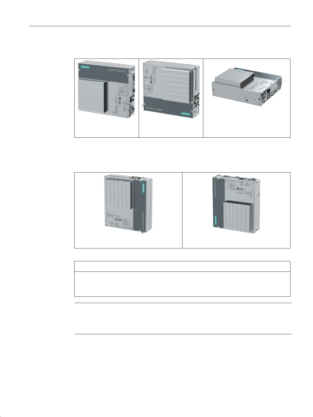
1.2
Design of the device
1.2.1
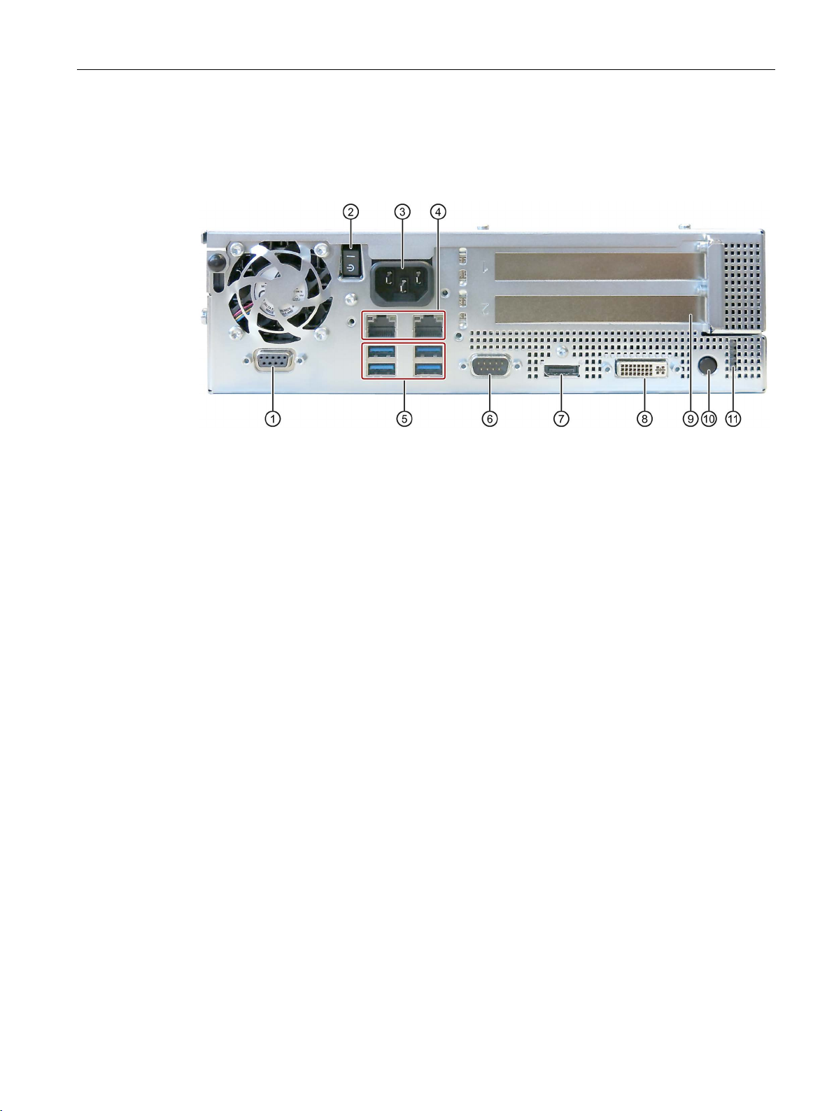
Operator controls and interfaces
Device with PROFIBUS interface
①
②
Position "OFF" is the factory state.
③
100-240 VAC
Power supply connection
④
⑤
4 × USB
USB 3.0 high current, backward compatible with USB 2.0/1.1
⑥
COM1
Serial interface
⑦
DisplayPort
DisplayPort connection for digital monitor
⑧
DVI-I
DVI connector for CRT or LCD monitor with DVI port
⑨
(optional)
⑩
switch. You then do not need to press the on/off button.
⑪
4 status LEDs
Status display of the operating state
1.2 Design of the device
PROFIBUS DP/MPI
fieldbus
On/off switch You switch on the device with the on/off switch. This requires that the
PROFIBUS DP/MPI interface (RS 485, isolated), 9-pin sub D socket
BIOS setup entry "After Power Failure" is set to "Power On".
The on/off switch does not isolate the device from the power supply.
Position "ON", when the "-)" symbol is pressed inward on the device.
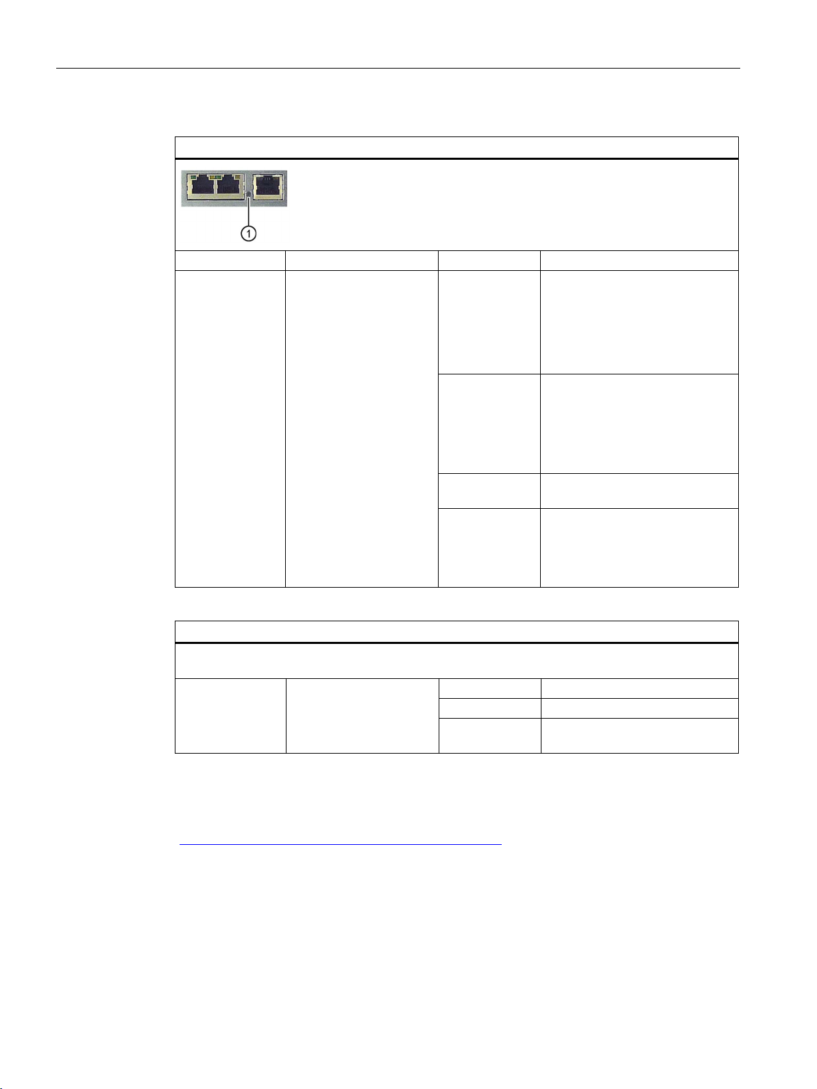
2 × Ethernet
PCI/PCIe expansion
cards,
COM2/LPT and USB
on expansion card
On/off button The on/off button has three functions:
• X1P1, left: RJ45 Ethernet port 1 (exclusive PCI interrupt) with
10/100/1000 Mbps, iAMT capable
• X2P1, right: RJ45 Ethernet port 2 (shared PCI interrupt) with
10/100/1000 Mbps
behind the cover
• Switch on the PC: Briefly press once
• Shut down operating system and switch off PC: Briefly press once
• Switch off PC without shutting down the operating system (hardware
reset): Press for more than 4 seconds.
Note: The BIOS setup entry "After Power Failure" has been set to
"Power On". This means the device is switched on with the on/off
SIMATIC IPC627D/827D
Operating Instructions, 09/2014, A5E32990859-AB
13
Overview
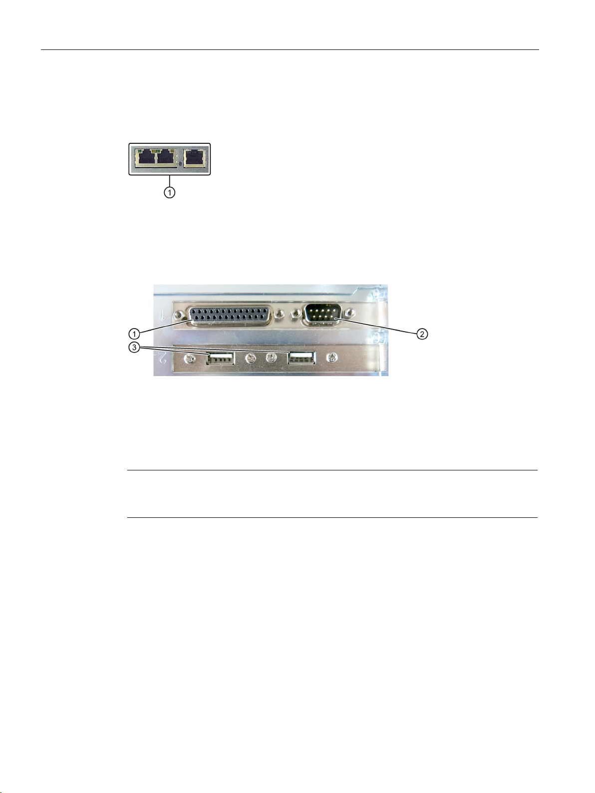
Device with PROFINET interface
①
CP 1616 onboard interface, three RJ45 sockets for devices with PROFINET, IRT capable
Device with COM2/LPT and USB expansion (optional)
①
LPT
②
COM
③
USB
Devices with resistive single-touch screen
Note
If you open the sealed cover for the front USB port, the degree of protection
front of the device is no longer guaranteed.
1.2 Design of the device
The following PROFINET interface is located at the position of the PROFIBUS interface ①
in the figure above:
The following expansion cards are located at the position of the cover ⑨ in the figure above:
IP65 for the
SIMATIC IPC627D/827D
14 Operating Instructions, 09/2014, A5E32990859-AB
Overview
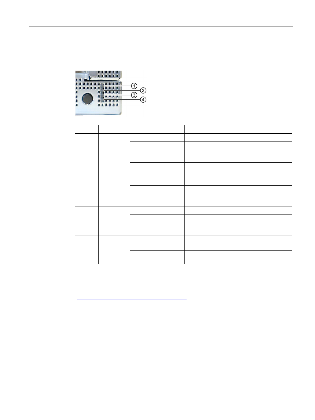
1.2.2
Status displays
Position
LED
State
Description
Off
-
Green
BIOS ready to boot
(1 Hz)
Yellow
Idle state
Flashing red (1 Hz)
Watchdog status display: active
Off
-
Green
Can be controlled by user program
WinAC)
③
Off
-
Red
-
Off
-
Yellow
-
WinAC)
1.2 Design of the device
The status display consists of four two-colored LEDs.
①
②
④
PC ON/WD
RUN/STOP /
L1
ERROR / L2
MAINT /
L3
Flashing green/yellow
Yellow Can be controlled by controller program (e.g.
Flashing red Can be controlled by user program or controller
Red Can be controlled by controller program (e.g.
BIOS in POST, power switch on
program (e.g. WinAC)
For additional information on controlling the LEDs or the SRAM with a Windows operating
system, please refer to the chapter "SRAM buffer memory (optional) (Page 55)". Example
programs for controlling the LEDs under Windows operating systems is available on the
Internet at the following address: Technical Support
(http://www.siemens.de/automation/csi_en_WW)
SIMATIC IPC627D/827D
Operating Instructions, 09/2014, A5E32990859-AB
15
Overview
PROFINET status display
Display
Meaning
LED
Description
Web or SNMP no longer possible
Virtual status displays
SNMP.
RUN
CP is active
STOP
CP is in the stop state
"fast flashing" states.
See also
1.2 Design of the device
① SF
PROFINET, optional
The two "virtual" CP 1616 LEDs can only be seen in the SIMATIC software and can be scanned via
Status display for CP
1616 onboard
OFF
Slow flashing
Fast flashing Exception error: Diagnostics via
AN
• CP not available
• CP disabled
• No error, communication
established
• Download in progress
• Link status error
• IO controller: IO device cannot
be addressed
• IO controller: Duplicate IP
address
• Diagnostic information
available
• No communication
established.
PROFINET Virtual LEDs
Industry Automation and Drive Technologies - Homepage
(http://www.siemens.com/automation/service&support)
SIMATIC IPC627D/827D
16 Operating Instructions, 09/2014, A5E32990859-AB
Flashes There are no "slow flashing" or
Overview
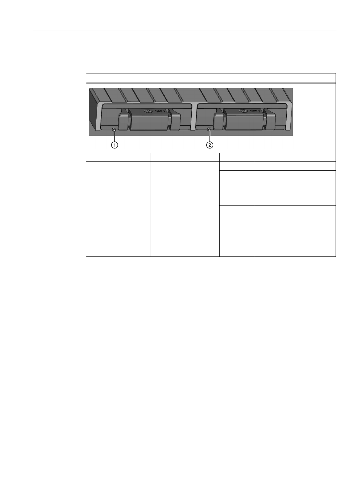
1.2.3
Removable drive bay status displays
RAID status display in removable drive bay
Display
Meaning
LED
Description
Both off
RAID is OK
lights up red
lights up red
RAID software".
Both flash
RAID is synchronizing
1.2 Design of the device
LED ① "HDD0 ALARM"
LED ② "HDD1 ALARM"
HDD alarm in connection
with RAID and monitoring
software
LED ①
LED ②
Both light up
red
HDD0 is not OK
HDD1 is not OK
RAID is not OK
For information on locating the
hard disk, see section
"Displaying a defective hard
disk of a RAID system in the
SIMATIC IPC627D/827D
Operating Instructions, 09/2014, A5E32990859-AB
17

Overview
1.2 Design of the device
SIMATIC IPC627D/827D
18 Operating Instructions, 09/2014, A5E32990859-AB

2
2.1
General safety instructions
WARNING
Life-threatening voltages are present with an open control cabinet
System expansions
NOTICE
Damage through system expansions
NOTICE
"Open Type" UL508
When you install the device in a control cabinet, some areas or components in the open
control cabinet may be carrying life-threatening voltages.
If you touch these areas or components, you may be killed by electric shock.
Switch off the power supply to the cabinet before opening it.
Device and system expansions may be faulty and can affect the entire machine or plant.
The installation of expansions can damage the device, machine or plant. Device and
system expansions may violate safety rules and regulations regarding radio interference
suppression. If you install or exchange system expansions and damage your device, the
warranty becomes void.
Note the following for system expansions:
● Only install system expansion devices designed for this device. Contact your technical
● Observe the information on electromagnetic compatibility (Page 102).
Note that the device is classified as "Open Type" for use in the area of Industrial Control
Equipment (UL508). Installation of the device in an enclosure complying with UL508 for
specific permitted mounting positions (see corresponding section) is a prerequisite for
approval or operation in accordance with UL508.
support team or where you purchased your PC to find out which system expansion
devices may safely be installed.
SIMATIC IPC627D/827D
Operating Instructions, 09/2014, A5E32990859-AB
19

Safety Instructions
WARNING
Risk of fire through expansion cards
Battery and rechargeable battery
WARNING
Risk of explosion and release of harmful substances
High frequency radiation
NOTICE
Unintentional operating situations
2.1 General safety instructions
Expansion cards generate additional heat. The device may overheat and cause a fire.
Please note the following:
• Observe the safety and installation instructions for the expansion cards.
• If in doubt, install the device in an enclosure that is compliant with sections 4.6 and 4.7.3
of the IEC/UL/EN/DIN-EN 60950-1 standard.
Improper handling of lithium batteries can result in an explosion of the batteries.
Explosion of the batteries and the released pollutants can cause severe physical injury.
Worn batteries jeopardize the function of the device.
Note the following when handling lithium batteries:
• Replace used batteries in good time; see the section "Replacing the backup battery" in
the operating instructions.
• Replace the lithium battery only with an identical battery or types recommended by the
manufacturer (order no.: A5E00331143).
• Do not throw lithium batteries into fire, do not solder on the cell body, do not recharge,
do not open, do not short-circuit, do not reverse polarity, do not heat above 100°C and
protect from direct sunlight, moisture and condensation.
High frequency radiation, e g. from a cellular phone, interferes with device functions and
can result in malfunctioning of the device.
Persons are injured and the plant is damaged.
Avoid high-frequency radiation:
• Remove radiation sources from the environment of the device.
• Switch off radiating devices.
• Reduce the radio output of radiating devices.
• Observe the information on electromagnetic compatibility (Page 102).
SIMATIC IPC627D/827D
20 Operating Instructions, 09/2014, A5E32990859-AB

Safety Instructions
ESD Guideline
NOTICE
Electrostatic sensitive devices (ESD)
Industrial Security
Disclaimer for third-party software updates
Notes on protecting administrator accounts
2.1 General safety instructions
Electrostatic sensitive devices can be labeled with an appropriate symbol.
When you touch electrostatic sensitive components, you can destroy them through voltages
that are far below the human perception threshold.
If you work with components that can be destroyed by electrostatic discharge, observe the
ESD Guideline (Page 103).
Siemens offers products and solutions with Industrial Security functions that support the safe
operation of equipment, solutions, machines, devices and/or networks. They are important
components in a comprehensive Industrial Security concept. As a result the products and
solutions from Siemens are constantly evolving. Siemens recommends obtaining regular
information regarding product updates.
For safe operation of Siemens products and solutions appropriate protective measures (e.g.,
cell protection concept) must be taken and each component must be integrated in a
comprehensive Industrial Security concept, which corresponds with the current state of
technology. The products of other manufacturers need to be taken into consideration if they
are also used. You can find addition information on Industrial Security under
(http://www.siemens.com/industrialsecurity).
Sign up for our product-specific newsletter to receive the latest information on product
updates. For more information, see under (http://www.siemens.de/automation/csi_en_WW).
This product includes third-party software. Siemens AG only provides a warranty for
updates/patches of the third-party software, if these have been distributed as part of a
Siemens software update service contract or officially released by Siemens AG. Otherwise,
updates/patches are undertaken at your own risk. You can find more information about our
Software Update Service offer on the Internet at Software Update Service
(http://www.automation.siemens.com/mcms/automation-software/en/software-update-
service/Pages/Default.aspx).
A user with administrator privileges has extensive access and manipulation options in the
system.
Therefore, ensure there are adequate safeguards for protecting the administrator accounts
to prevent unauthorized changes. To do this, use secure passwords and a standard user
account for normal operation. Other measures, such as the use of security policies, should
be applied as needed.
SIMATIC IPC627D/827D
Operating Instructions, 09/2014, A5E32990859-AB
21

Safety Instructions
2.2
Notes on use
NOTICE
Possible functional limitations if operation of plant is not validated
NOTICE
Ambient conditions
Note
Use in an industrial environment without additional protective measures
This device was designed for use in a normal industrial environment according to
IEC
2.2 Notes on use
The device has been tested and certified based on technical standards. In rare cases, you
may encounter functional limitations when operating your plant.
To avoid such functional limitations, you should validate the correct operation of the plant.
Ambient conditions for which the device is not suitable can cause faults or damage the
device.
Note the following:
• Operate the device only in closed rooms. Failure to comply nullifies the warranty.
• Operate the device only in accordance with the ambient conditions specified in the
technical specifications.
• Protect the device against dust, moisture and heat.
• Do not expose the device to direct sunlight or other strong sources of light.
• Without additional measures, such as a supply of clean air, the device may not be used
in locations with harsh operating conditions caused by acidic vapors or gases.
• Observe the permitted mounting positions of the device.
• Do not obstruct the venting slots of the device.
60721-3-3.
SIMATIC IPC627D/827D
22 Operating Instructions, 09/2014, A5E32990859-AB

3
3.1
Preparing for installation
3.1.1
Checking the delivery package
Procedure
Note
Damage to the device during transport and storage
If a device is transported or stored without packaging, shocks, vibrations, pressure and
moisture may impact the unprotected unit. Damaged packaging indicates that ambient
conditions have already h
This may cause the device, machine or plant to malfunction.
•
•
1. When accepting a delivery, please check the packaging for visible transport damage.
2. If any transport damage is present at the time of delivery, lodge a complaint at the
shipping company in charge. Have the shipper confirm the transport damage
immediately.
3. Unpack the device at its installation location.
4. Keep the original packaging in case you have to transport the unit again.
ad a massive impact on the device and it may be damaged.
Keep the original packaging.
Pack the device in the original packaging for transportation and storage.
5. Check the contents of the packaging and any accessories you may have ordered for
completeness and damage.
SIMATIC IPC627D/827D
Operating Instructions, 09/2014, A5E32990859-AB
23

Installing and connecting the device
WARNING
Electric shock and fire hazard due to damaged device
NOTICE
Damage from condensation
3.1 Preparing for installation
6. Please inform the delivery service immediately if the package contents are incomplete or
damaged or do not correspond with your order. Fax the enclosed form "SIMATIC IPC/PG
Quality Control Report".
A damaged device can be under hazardous voltage and trigger a fire in the machine or
plant. A damaged device has unpredictable properties and states.
Death or serious injury could occur.
Make sure that the damaged device is not inadvertently installed and put into operation.
Label the damaged device and keep it locked away. Send off the device for immediate
repair.
If the device is subjected to low temperatures or extreme fluctuations in temperature
during transportation, as is the case in cold weather, for example, moisture can build up
on or inside the device (condensation).
Moisture causes a short circuit in electrical circuits and damages the device.
In order to prevent damage to the device, proceed as follows:
• Store the device in a dry place.
• Bring the device to room temperature before starting it up.
• Do not expose the device to direct heat radiation from a heating device.
• If condensation develops, wait approximately 12 hours or until the device is
completely dry before switching it on.
7. Please keep the enclosed documentation in a safe place. It belongs to the device. You
need the documentation when you commission the device for the first time.
8. Write down the identification data of the device.
SIMATIC IPC627D/827D
24 Operating Instructions, 09/2014, A5E32990859-AB
Installing and connecting the device
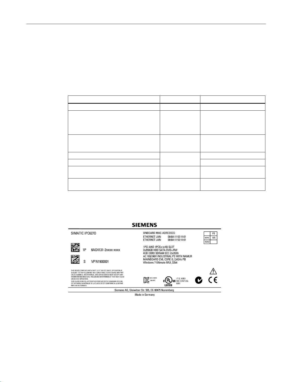
3.1.2
Identification data of the device
Unpacking the device
Identification date
Source
Value
Serial number
Nameplate
S VP ...
have COA labels
Ethernet address 1
Ethernet address 2
CP 1616 onboard MAC Address Layer 2 (only
for PROFINET devices)
(only for PROFINET devices)
Nameplate
3.1 Preparing for installation
The device can be identified uniquely with the help of these numbers in case of repairs or
theft.
Enter the identification data in the table below:
Order number of the device Nameplate 6AG4131-2... SIMATIC
IPC627D
6AG4132-2... SIMATIC
IPC827D
Microsoft Windows Product Key
Certificate of Authenticity (COA)
Back of the device Only devices with preinstalled
Windows operating systems
BIOS setup, "Main"
menu
CP 1616 onboard MAC address PROFINET
The following image shows the nameplate on the SIMATIC IPC627D as an example.
SIMATIC IPC627D/827D
Operating Instructions, 09/2014, A5E32990859-AB
25
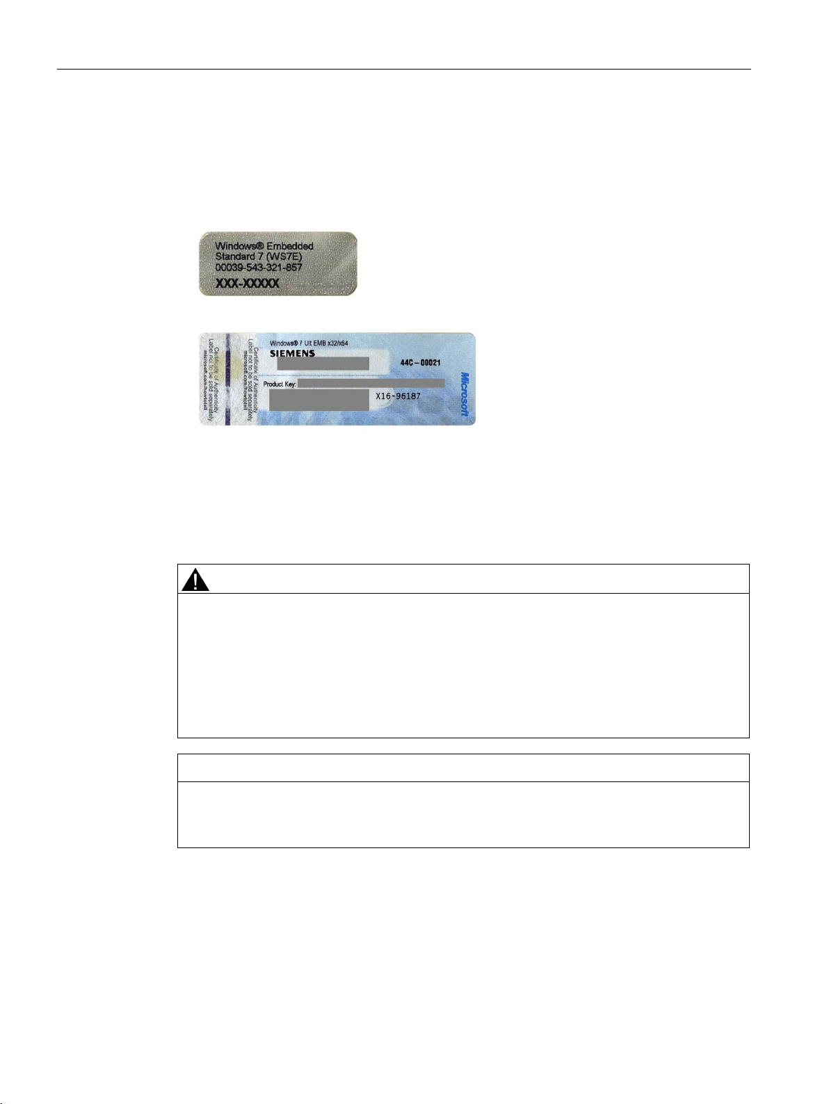
Installing and connecting the device
Example of a COA label
3.1.3
Permitted mounting positions
Mounting positions according to UL60950-1/UL508/EN60950-1/CSA22.2 No. 60950-1
CAUTION
Points to note with expansion cards
NOTICE
Operation only in closed rooms
3.1 Preparing for installation
Microsoft Windows "Product Key" on the "Certificate of Authenticity" (COA):
The COA label is only attached to the rear of the device containing a Windows Embedded
Standard 7 or Windows 7 operating system.
● COA label of a device with Windows Embedded Standard 7 operating system
● COA label of a device with Windows 7 operating system
Expansion cards may impose restrictions on the installation location (fire-proof enclosure)
and permitted mounting positions (see Technical specifications). If the device has been
fitted with expansion cards, please observe the safety and installation instructions for the
expansion cards in the corresponding documentation.
If in doubt, install the device in an enclosure that is compliant with
IEC/UL/EN/DIN-EN 60950-1, sections 4.6 and 4.7.3.
The device is only approved for operation in closed rooms. Pay attention to the ambient
and environmental conditions.
SIMATIC IPC627D/827D
26 Operating Instructions, 09/2014, A5E32990859-AB
Installing and connecting the device
interfaces are at the right.
Additional mounting positions according to UL508/CSA 22.2 No. 142
CD/DVD drive may not be operated.
CD/DVD drive may not be operated.
NOTICE
Points to note for position 4 and 5
Note
Mounting positions 4 and 5 are also permitted for the Information Technology Equipme
area when the device is mounted in an enclosure that fulfills the requirements stipulated by
sections 4.6 and 4.7.3 of IEC/UL/EN/DIN EN 60950
3.1 Preparing for installation
An inclination of ± 20° is permitted for all approved mounting positions.
Position 3 (desktop)
Position 1 (preferred) for
wall mounting: The
Position 2 for wall mounting:
The interfaces are at the left.
An inclination of ±15° is allowed in this mounting position.
Position 4 (interfaces facing down)
Position 5 (interfaces facing up)
CD/DVD and floppy drives cannot be operated in this position. The CD drawer opens
upward or downward, which can lead to mechanical damage in the drawer mechanism.
nt
-1.
SIMATIC IPC627D/827D
Operating Instructions, 09/2014, A5E32990859-AB
27

Installing and connecting the device
3.2
Installing the device
3.2.1
Installation guidelines
NOTICE
Voided approvals
3.2.2
Mounting instructions
3.2 Installing the device
When you plan your project, take note of the following points:
● Take note of the climatic and mechanical ambient conditions (Page 117).
● This device was designed for use in a normal industrial environment. Without additional
protective measures (such as the provision of clean air), SIMATIC Box PCs may not be
operated in harsh environments that are subject to caustic vapors or gases.
● Do not cover the vent slots of the device.
● The device together with its AC power supply fulfils the requirements for fire protected
enclosures according to EN 60950-1. Therefore it can be installed without any additional
fire protective covering.
● The device with DC power supply does not fulfill the requirements according to
EN 60950-1 in the power supply unit area. The device must therefore be installed so that
it is part of a restricted access location (e.g. a locked switchgear cabinet, control panel or
server room).
Failure to adhere to these conditions when mounting the system voids the approvals
based on UL 60950-1, UL 508 and EN 60950-1!
● At least 100 mm space should be left free around the ventilation slots, in order that the
PC receives sufficient ventilation.
Note the following:
● Always observe the mounting positions permitted for this device.
● The device is only approved for operation in closed rooms.
● For installation in a control cabinet, observe the SIMATIC installation guidelines and
applicable DIN/VDE requirements or other applicable country-specific regulations.
● When the device is used in the area of Industrial Control Equipment in accordance with
UL508, note that the device is classified as "Open Type". The installation of the device in
a housing conforming to UL508 is therefore a mandatory requirement for approval or
operation in accordance with UL508.
SIMATIC IPC627D/827D
28 Operating Instructions, 09/2014, A5E32990859-AB
Installing and connecting the device
Securing the device
NOTICE
Insufficient load carrying capacity
NOTICE
Incorrect fixing elements
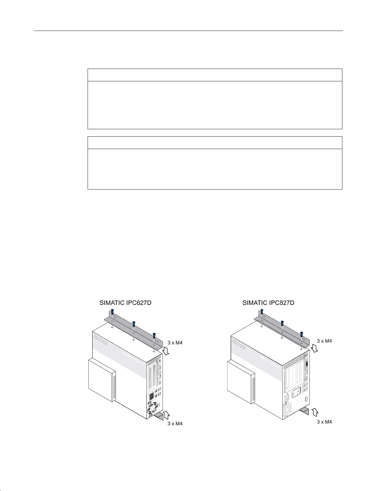
3.2.3
Installing the device with mounting brackets
Screw-mounting the brackets
3.2 Installing the device
If the wall it is mounted on does not have a sufficient load-bearing capacity, the device may
fall and be damaged.
Ensure that the mounting surface on the wall can bear four times the total weight of the
device, including fixing elements.
The device may not be securely fitted if you use anchors and screws other than those
specified below for mounting. The device can fall and may be damaged.
Use only the anchors and screws specified in the following table.
Two angle brackets are included in the product package.
Secure the two brackets with six M4x6 screws, maximum penetration depth 5 mm, to the
device. Use the marked threaded holes.
SIMATIC IPC627D/827D
Operating Instructions, 09/2014, A5E32990859-AB
29
Installing and connecting the device
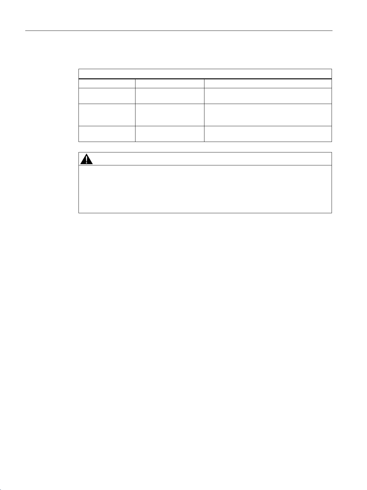
Instructions for wall mounting
Mounting examples
Material
Hole diameter
Mounting
thick)
(at least 2 mm thick)
at least 15 mm long
WARNING
Personal injuries or material damage in the case of insufficient load-bearing capacity of wall
3.2 Installing the device
Concrete 8 mm diameter,
60 mm depth
Plasterboard
(at least 13 mm
Metal
14 mm diameter Tilting dowel: 4 mm diameter,
5 mm diameter Metal screws: 4 mm diameter,
Dowel: 8 mm diameter, 50 mm length
screws 4.5-6 x 50 mm
at least 50 mm long
The device could fall if the wall to which it is mounted has insufficient load-bearing capacity.
This can result in personal injuries or material damage.
Ensure that the wall is capable of bearing four times the total weight of the device (including
the brackets and expansion modules). The total weight of the device is approximately 7 kg.
SIMATIC IPC627D/827D
30 Operating Instructions, 09/2014, A5E32990859-AB
 Loading...