

Siemens SIMATIC IPC627C Getting Started

SIMATIC IPC627C
_
_________________
_
_
_________________
_
_
_________________
_
_
_________________
_
_
_________________
_
_
_________________
_
_
_________________
_
_
_________________
_
_
_________________
_
SIMATIC
Industrie PC
SIMATIC IPC627C
Getting Started
09/2011
A5E02669077-03
Introduction
1
Description
2
Application planning
3
Mounting
4
Connecting
5
Commissioning
6
Troubleshooting
7
Dimensional drawings
8
Appendix
A

Legal information
Legal information
Warning notice system
This manual contains notices you have to observe in order to ensure your personal safety, as well as to prevent
damage to property. The notices referring to your personal safety are highlighted in the manual by a safety alert
symbol, notices referring only to property damage have no safety alert symbol. These notices shown below are
graded according to the degree of danger.
DANGER
indicates that death or severe personal injury will result if proper precautions are not taken.
WARNING
indicates that death or severe personal injury may result if proper precautions are not taken.
CAUTION
with a safety alert symbol, indicates that minor personal injury can result if proper precautions are not taken.
CAUTION
without a safety alert symbol, indicates that property damage can result if proper precautions are not taken.
NOTICE
indicates that an unintended result or situation can occur if the relevant information is not taken into account.
If more than one degree of danger is present, the warning notice representing the highest degree of danger will
be used. A notice warning of injury to persons with a safety alert symbol may also include a warning relating to
property damage.
Qualified Personnel
The product/system described in this documentation may be operated only by personnel qualified for the specific
task in accordance with the relevant documentation, in particular its warning notices and safety instructions.
Qualified personnel are those who, based on their training and experience, are capable of identifying risks and
avoiding potential hazards when working with these products/systems.
Proper use of Siemens products
Note the following:
WARNING
Siemens products may only be used for the applications described in the catalog and in the relevant technical
documentation. If products and components from other manufacturers are used, these must be recommended
or approved by Siemens. Proper transport, storage, installation, assembly, commissioning, operation and
maintenance are required to ensure that the products operate safely and without any problems. The permissible
ambient conditions must be complied with. The information in the relevant documentation must be observed.
Trademarks
All names identified by ® are registered trademarks of Siemens AG. The remaining trademarks in this publication
may be trademarks whose use by third parties for their own purposes could violate the rights of the owner.
Disclaimer of Liability
We have reviewed the contents of this publication to ensure consistency with the hardware and software
described. Since variance cannot be precluded entirely, we cannot guarantee full consistency. However, the
information in this publication is reviewed regularly and any necessary corrections are included in subsequent
editions.
Siemens AG
Industry Sector
Postfach 48 48
90026 NÜRNBERG
GERMANY
A5E02669077-03
Ⓟ 09/2011
Copyright © Siemens AG 2011.
Technical data subject to change

SIMATIC IPC627C
Getting Started, 09/2011, A5E02669077-03
3
Table of contents
1 Introduction................................................................................................................................................ 5
2 Descri
ption................................................................................................................................................. 7
2.1 Exterior des
ign ...............................................................................................................................7
2.2 Operator C
ontrols ..........................................................................................................................9
2.3 Connection elements
...................................................................................................................11
2.4 Status dis
plays.............................................................................................................................15
3 Application pl
anning................................................................................................................................. 17
3.1 Transp
ort......................................................................................................................................17
3.2 Unpacking and c
hecking the delivery unit ...................................................................................17
3.3 Device identification data................................................................................................
.............18
3.4 Ambient and envi
ronmental conditions........................................................................................19
3.5 Permitted mounting posi
tions.......................................................................................................20
4 Mounting.....................................................
............................................................................................. 23
4.1 Inst
alling the device .....................................................................................................................23
4.2 Installing the devi
ce with mounting brackets ...............................................................................24
4.3 Inst
alling the device with the vertical mounting kit.......................................................................24
4.4 Inst
alling the device with the vertical mounting kit for PC port access from the front..................27
5 Connecting
.............................................................................................................................................. 29
5.1 Connecting peripherals
................................................................................................................29
5.2 Connecting the 100 - 240 V AC Power
Supply............................................................................30
5.3 Connecting the (24 V) DC
power supply .....................................................................................33
5.4 Connecting equipotential bonding................................................................................................35
6 Commissioni
ng ........................................................................................................................................ 37
6.1 Requirements
for commissioning.................................................................................................37
6.2 Basi
c commissioning - initial startup............................................................................................38
6.3 Reinst
alling the software..............................................................................................................38
6.3.1 General installation proc
edure.....................................................................................................38
7 Troubles
hooting....................................................................................................................................... 39
7.1 General problems ..........................................................................................................
..............39
8 Dimens
ional drawings.............................................................................................................................. 41
8.1 Dimensional
drawings of the device ............................................................................................41

Table of contents
SIMATIC IPC627C
4 Getting Started, 09/2011, A5E02669077-03
A Appendix.................................................................................................................................................. 45
A.1 Guidelines and declarations........................................................................................................ 45
A.2 Certificates and approv
als........................................................................................................... 46
A.3 Servic
e and support .................................................................................................................... 49
Index
........................................................................................................................................................ 51

SIMATIC IPC627C
Getting Started, 09/2011, A5E02669077-03
5
Introduction
1
Purpose of this document
This Getting Started documentation contains all the information you need for commissioning
and using the SIMATIC IPC627C.
Scope of validity of this document
This documentation is valid for all supplied versions of the SIMATIC IPC627C.
SIMATIC IPC627C, Operating Instructions
The operating instructions are available on the supplied "Documentation and Drivers" CD. To
view and print the operating instructions, run Start and follow the instructions on the screen.
The operating instructions provide useful information on many topics such as the hardware
expansion options, modification of the system configuration and technical data.
Conventions
The term "Box PC" or "device" is sometimes used to refer to the SIMATIC IPC627C product
in this documentation. The abbreviation "CP" stands for CP 1616 onboard.

Introduction
SIMATIC IPC627C
6 Getting Started, 09/2011, A5E02669077-03
SIMATIC IPC627C
Getting Started, 09/2011, A5E02669077-03
7
Description
2
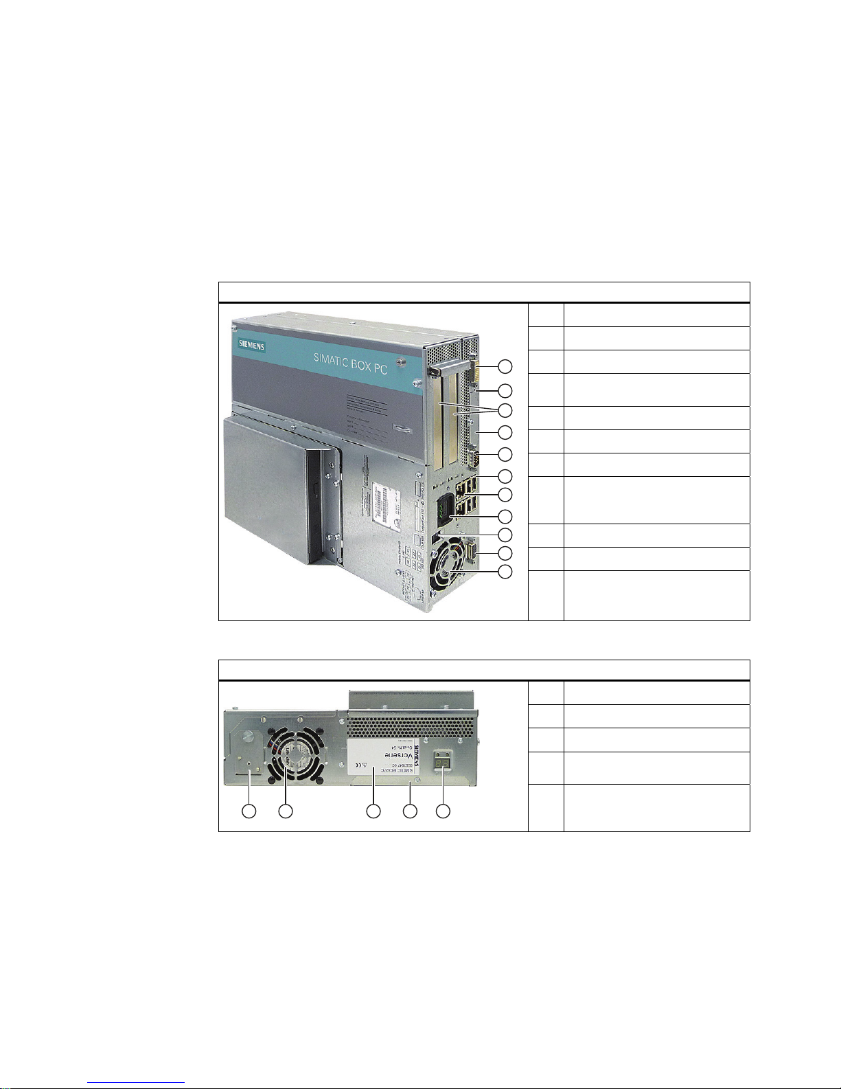
2.1 Exterior design
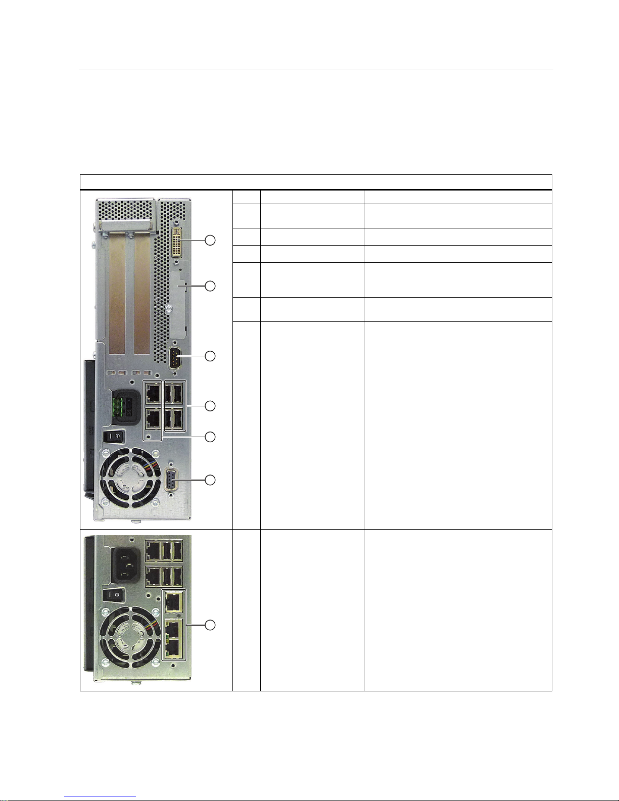
Front view
①
DVI/VGA port
②
On/off button
③
2 slots for expansion modules
④
Cover for Compact Flash Card
slot
⑤
COM interface
⑥
4 USB ports
⑦
2 RJ 45 Ethernet connections
⑧
IEC connector for AC power
supply or connection for DC
power supply
⑨
On / Off switch
⑩
PROFIBUS or PROFINET ports
⑪
Power supply fan
Rear view
①
Battery compartment
②
Device fan
③
Rating label with serial number
④
Steel cover plate for the operator
panel interfaces
⑤
Status display: Two part 7
segment display and two LEDs for
POST code (optional)
Description
2.1 Exterior design
SIMATIC IPC627C
8 Getting Started, 09/2011, A5E02669077-03
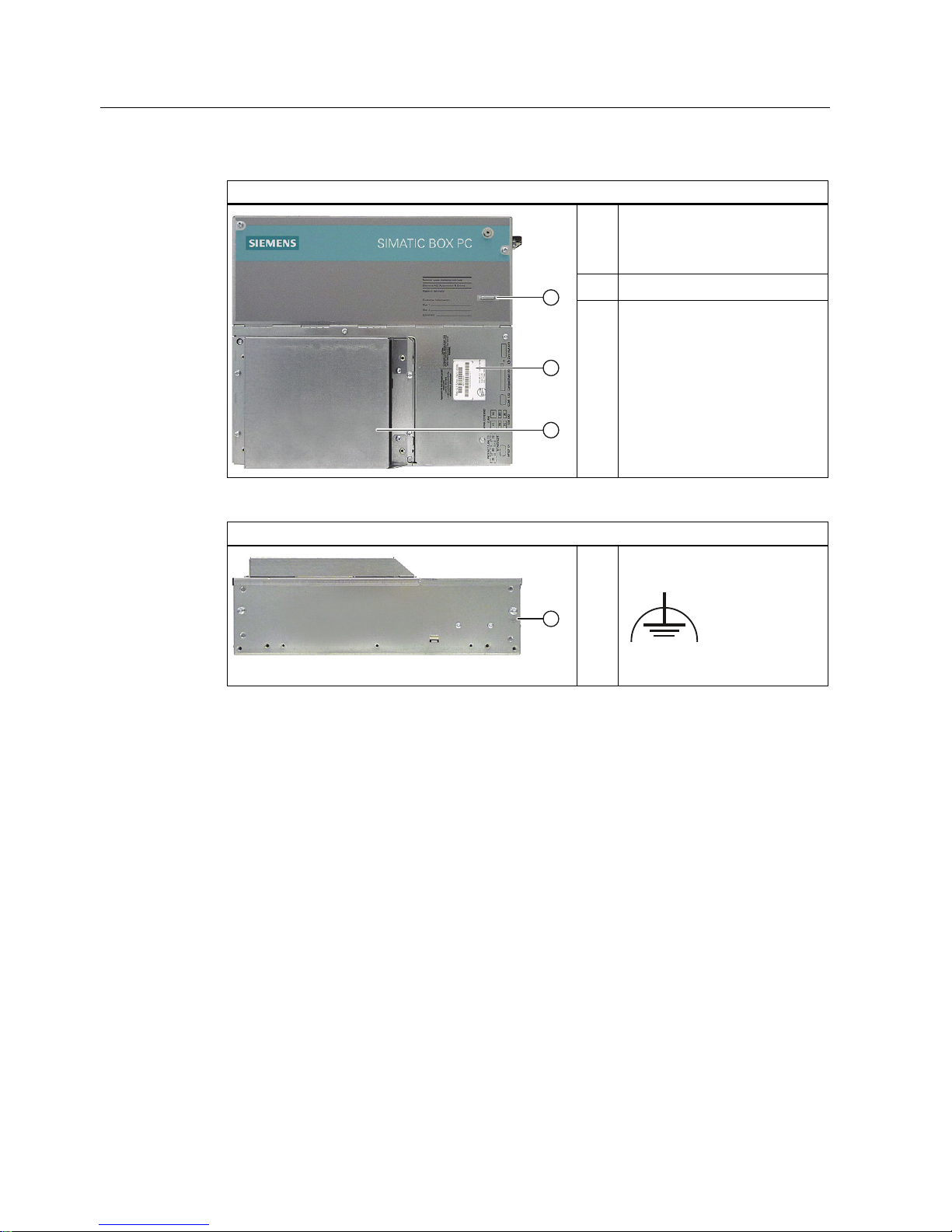
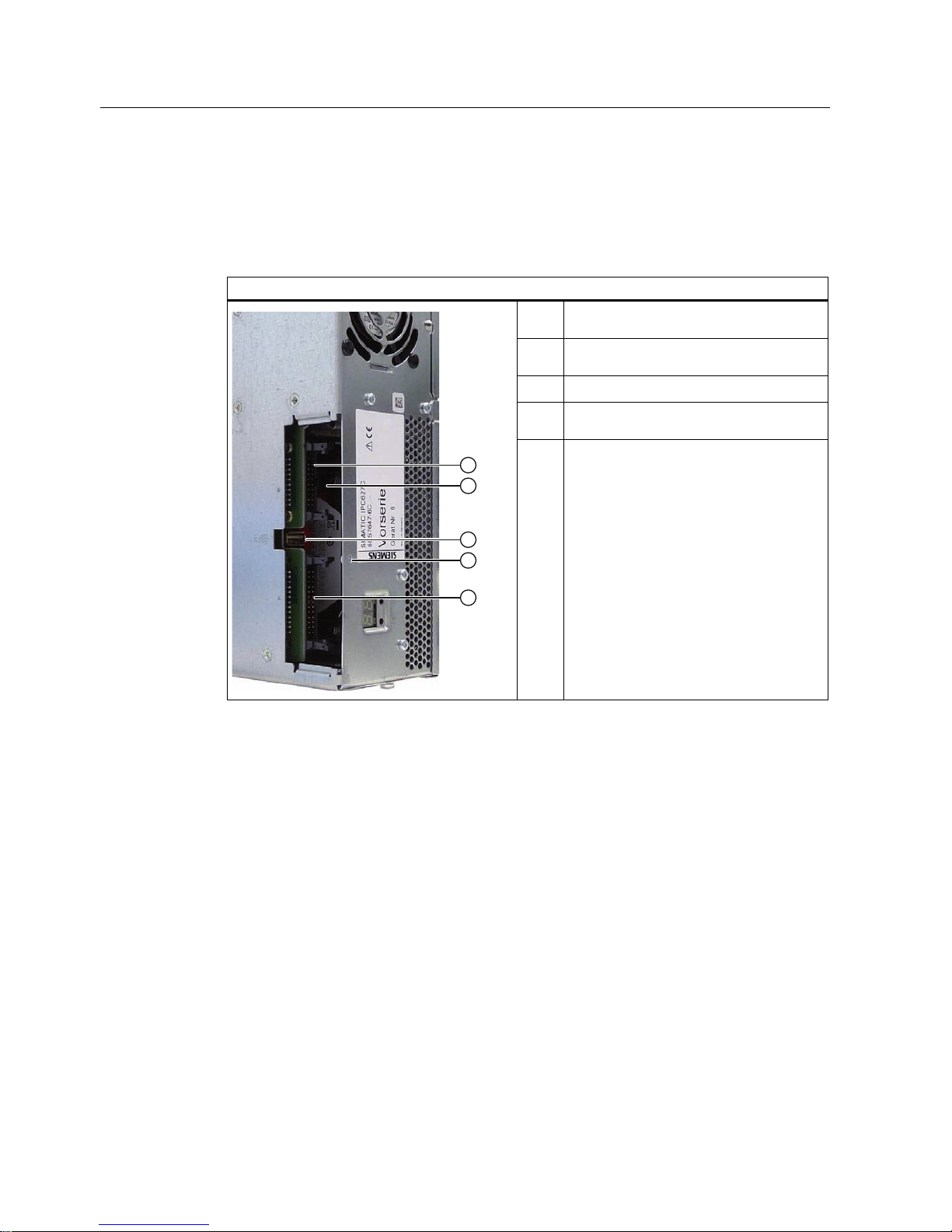
Side view (drive side)
①
Mounting for WinAC backup
battery (please use the supplied
battery mount without cover for
WinAC module)
②
Input data of the power supply
③
Drive bay module for hard disks
and DVD burner
Bottom
①
Connection for equipotential
bonding
Description
2.2 Operator Controls
SIMATIC IPC627C
Getting Started, 09/2011, A5E02669077-03
9
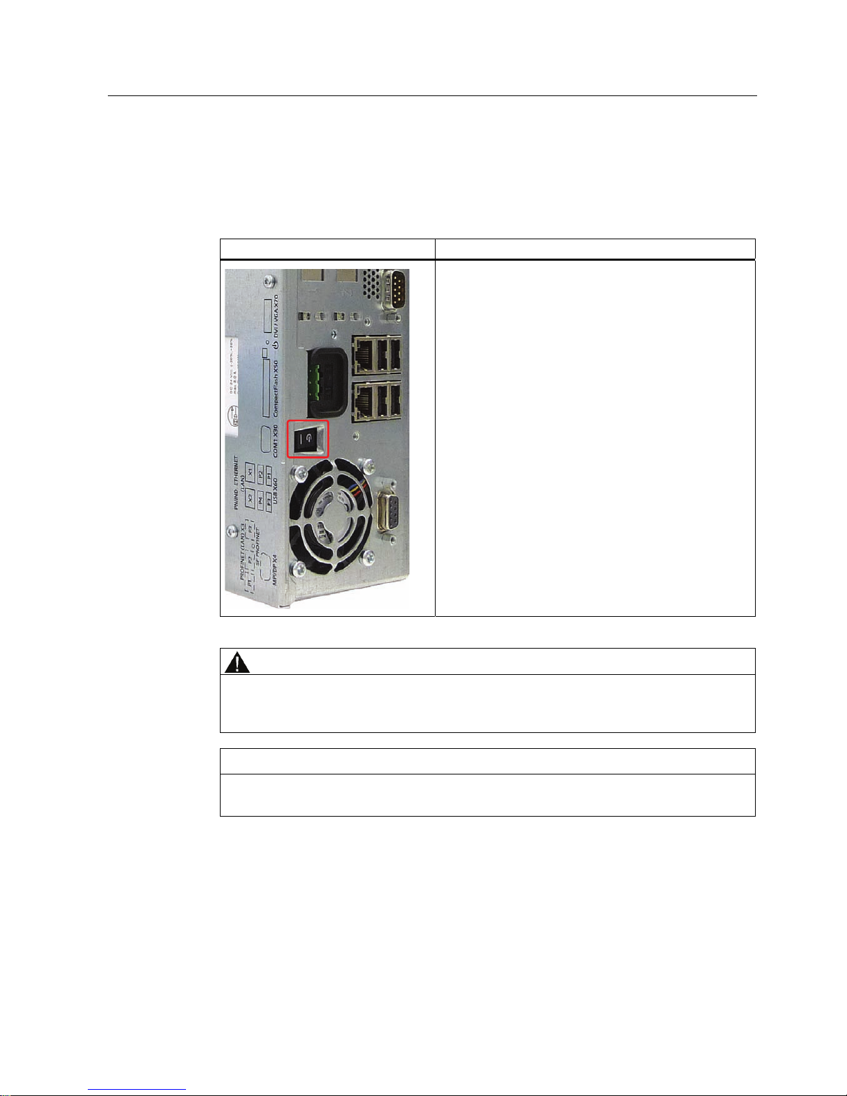
2.2 Operator Controls
On/Off switch
On/Off switch Description
Switch the device on using the on/off switch. This requires
that the BIOS Setup entry "After Power Failure" is set to
"Power On".
WARNING
The on/off switch does not isolate the device from the mains! When the switch is in 0
position (Off), the device is still supplied with mains voltage in order to generated the
internal auxiliary voltage for the power supply.
NOTICE
Terminate the operating system before shutting down the device with the on/off switch,
otherwise data may be lost.
Description
2.2 Operator Controls
SIMATIC IPC627C
10 Getting Started, 09/2011, A5E02669077-03
On/off button
On/off button Description
The on/off button has three functions:
- Switch on the PC (press briefly 1x)
- Shut down the operating system and PC
(press briefly 1x)
- Switch off the PC without shutting down the
operating system
(press and hold more than 4 seconds) =
hardware reset.
CAUTION
Data may be lost when the PC performs a hardware reset.
WARNING
The on/off button does not isolate the device from the mains!
Note
By default, the BIOS Setup entry "After Power Failure" is set to "Power On". This means the
device is switched on with the on/off switch and you do not have to operate the on/off button.
Description
2.3 Connection elements
SIMATIC IPC627C
Getting Started, 09/2011, A5E02669077-03
11
2.3 Connection elements
Interfaces
Arrangement of the interfaces on the front of the device
Item Description Description
①
DVI/VGA DVI/VGA connection for CRT or LCD monitor
with DVI interface, VGA via DVI/VGA adapter
②
Compact Flash card Slot for Compact Flash card
③
COM Serial V.24 port
④
USB 2.0 4 ports for USB devices
(only 2 ports can be simultaneously used as
high current)
⑤
ETHERNET 2x RJ 45 Ethernet connection for 10/100/1000
Mbps
⑥
PROFIBUS/MPI MPI interface (RS485, electrically isolated),
optional 9-pin D-sub socket (optional product
model)
⑦
PROFINET CP 1616 onboard interface, three RJ45 sockets
(optional product models)
Description
2.3 Connection elements
SIMATIC IPC627C
12 Getting Started, 09/2011, A5E02669077-03
The interfaces available on the device can be uniquely identified based on their numbering.
This numbering may deviate, however, from the numbering performed by the operating
system.
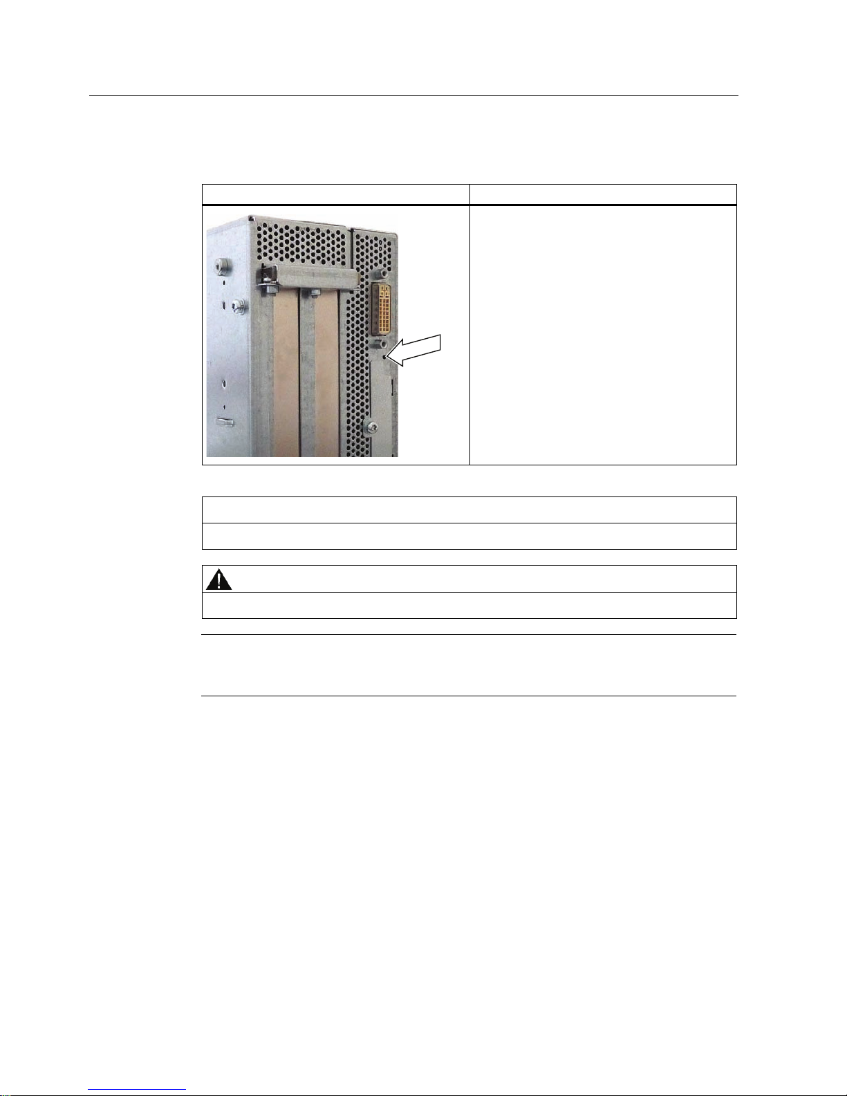
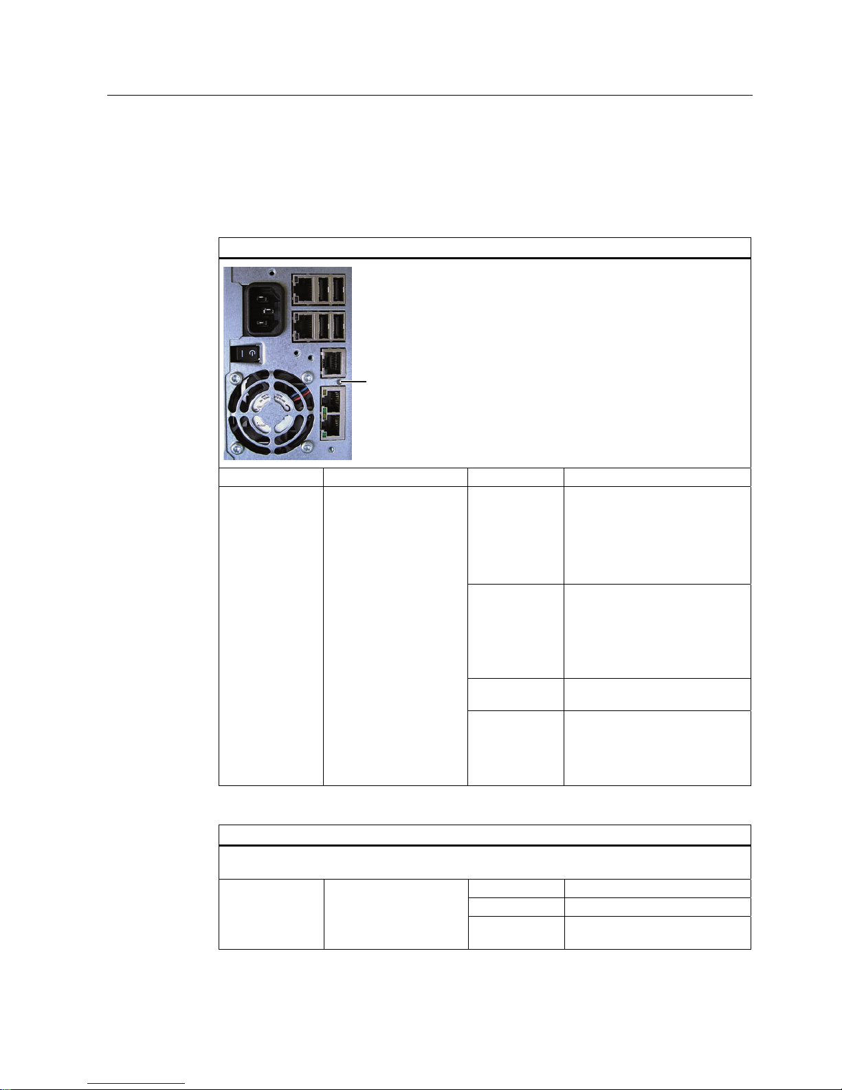
Interfaces for connecting operator panels / displays
Arrangement of the interfaces
①
LVDS display interface
for TFT displays up to 1024 x 768 pixels
②
Access to 2nd LVDS display interface for
TFT displays up to 1280 x 1024
③
USB 2.0 for front
④
Retaining screw for the steel cover plate
that covers the interfaces described below.
⑤
I/O interface for connecting front panel
components
Description
2.3 Connection elements
SIMATIC IPC627C
Getting Started, 09/2011, A5E02669077-03
13
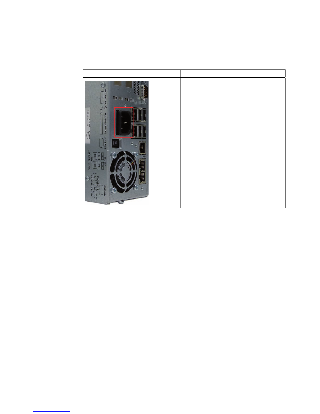
AC power supply
Position of the IEC power connector Description
IEC power connector to AC power supply of the
device. The maximum permitted power range is
100 VAC to 240 VAC.
Description
2.3 Connection elements
SIMATIC IPC627C
14 Getting Started, 09/2011, A5E02669077-03
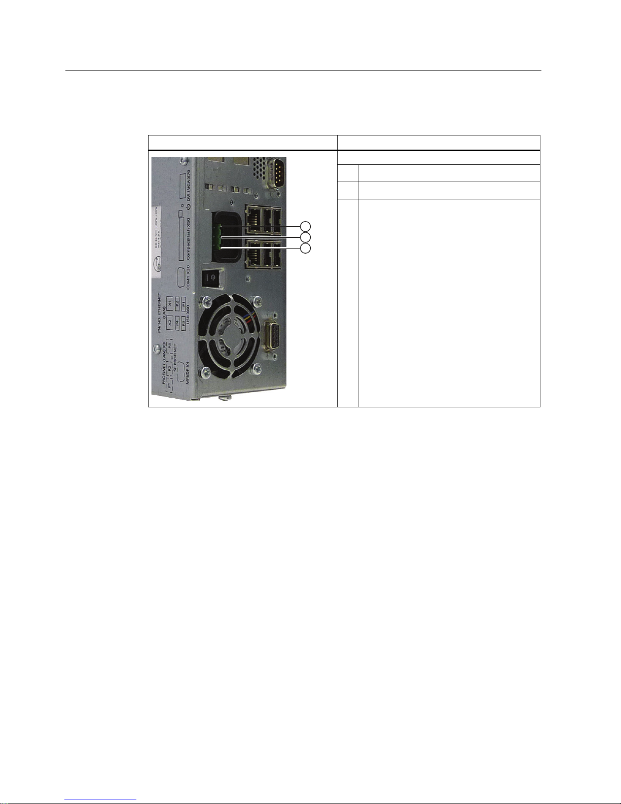
DC power supply
Position of the DC power connector Description
Plug connector for DC power supply of the device
①
+ (24 V DC)
②
- (ground)
③
PE (ground terminal)
Description
2.4 Status displays
SIMATIC IPC627C
Getting Started, 09/2011, A5E02669077-03
15
2.4 Status displays
PROFINET status display
PROFINET status display
6)352),1(7
Display Meaning LED Description
OFF
CP not available
CP disabled
No error, communication
established
Download in progress
Slow flashing
Link status error
IO controller: IO device cannot
be addressed
IO controller: Duplicate IP
address
Fast flashing Exception error: Diagnostics via
Web or SNMP no longer possible
SF PROFINET
(optional)
Status display for
CP 1616 onboard
AN
Diagnostic information
available
No communication
established.
Virtual status displays
The two "virtual" CP 1616 LEDs can only be seen in the SIMATIC software and can be scanned via
SNMP.
RUN CP is active
STOP CP is in the stop state
PROFINET Virtual LEDs
Flashes There are no "slow flashing" or
"fast flashing" states.
Description
2.4 Status displays
SIMATIC IPC627C
16 Getting Started, 09/2011, A5E02669077-03
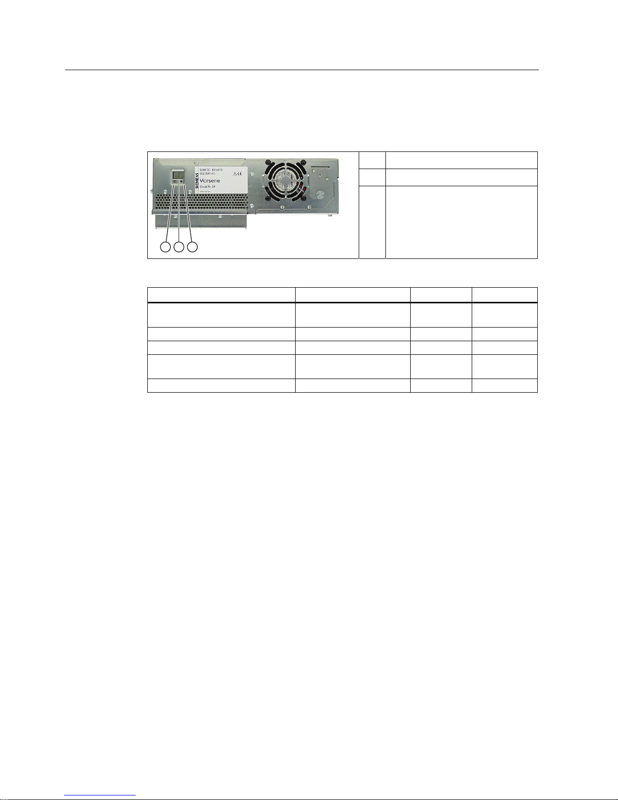
Status display
The status display consists of two 7-segment displays and two three-color LEDs.
①
LED H1 (red, yellow, orange)
②
2 x 7-segment display
③
LED H2 (red, yellow, orange)
7 segment display LED H1 LED H2
Power On
(= status display test)
88h Orange Orange
BIOS self-test xxh (see BIOS post code) Off Off
BIOS self-test completed 00h Off Off
Operating system running or
controlled by application
00h Off Off
Operating system shutting down Off Off Off
 Loading...