

Siemens Simatic IPC547E Operating Instructions Manual

SIMATIC IPC547E
___________________
___________________
___________________
___________________
___________________
___________________
___________________
___________________
___________________
___________________
___________________
SIMATIC
Industrial PC
SIMATIC IPC547E
Operating Instructions
02/2014
A5E32317120
Preface
Overview
1
Safety instructions
2
Installing and connecting the
device
3
Commissioning the device
4
Expanded device functions
5
Expanding and assigning
parameters to the device
6
Device maintenance and
repair
7
Technical specifications
8
Technical support
A
List of abbreviations
B
-AB
Siemens AG
Industry Sector
Postfach 48 48
90026 NÜRNBERG
GERMANY
A5E32317120-AB
Ⓟ
Copyright © Siemens AG 2014.
All rights reserved
Warning notice system
DANGER
indicates that death or severe personal injury will result if proper precautions are not taken.
WARNING
indicates that death or severe personal injury may result if proper precautions are not taken.
CAUTION
indicates that minor personal injury can result if proper precautions are not taken.
NOTICE
indicates that property damage can result if proper precautions are not taken.
Qualified Personnel
personnel qualified
Proper use of Siemens products
WARNING
Siemens products may only be used for the applications described in the catalog and in the relevant technical
maintenance are required to ensure that the products operate safely and without any problems. The permissible
ambient conditions must be complied with. The information in the relevant documentation must be observed.
Trademarks
Disclaimer of Liability
Legal information
This manual contains notices you have to observe in order to ensure your personal safety, as well as to prevent
damage to property. The notices referring to your personal safety are highlighted in the manual by a safety alert
symbol, notices referring only to property damage have no safety alert symbol. These notices shown below are
graded according to the degree of danger.
If more than one degree of danger is present, the warning notice representing the highest degree of danger will
be used. A notice warning of injury to persons with a safety alert symbol may also include a warning relating to
property damage.
The product/system described in this documentation may be operated only by
task in accordance with the relevant documentation, in particular its warning notices and safety instructions.
Qualified personnel are those who, based on their training and experience, are capable of identifying risks and
avoiding potential hazards when working with these products/systems.
Note the following:
for the specific
documentation. If products and components from other manufacturers are used, these must be recommended
or approved by Siemens. Proper transport, storage, installation, assembly, commissioning, operation and
All names identified by ® are registered trademarks of Siemens AG. The remaining trademarks in this publication
may be trademarks whose use by third parties for their own purposes could violate the rights of the owner.
We have reviewed the contents of this publication to ensure consistency with the hardware and software
described. Since variance cannot be precluded entirely, we cannot guarantee full consistency. However, the
information in this publication is reviewed regularly and any necessary corrections are included in subsequent
editions.
02/2014 Technical data subject to change

Preface
Basic knowledge required
Validity of the Operating Instructions
Scope of this documentation
Conventions
History
Version
Comments
09/2013
First edition
02/2014
2. Edition
These operating instructions contain all the information you need for commissioning and
operation of the SIMATIC IPC547E.
It is intended both for programming and testing personnel who commission the device and
connect it with other units (automation systems, programming devices), as well as for service
and maintenance personnel who install add-ons or carry out fault/error analyses.
A solid background in personal computers and Microsoft operating systems is required to
understand this manual. General knowledge in the field automation control engineering is
recommended.
These operating instructions are valid for all supplied versions of the SIMATIC IPC547E.
The documentation for the SIMATIC IPC547E includes the following sections:
● Product Information "Important notes on your device"
● Quick Install Guide SIMATIC IPC547E
● SIMATIC IPC547E operating instructions in English and German
The documentation is part of the "Documentation and Drivers" DVD supplied with the
product.
Refer to the corresponding user documentation for information and instructions on using
software.
The terms "PC" or "device" are sometimes used in place of the product name
SIMATIC IPC547E in these operating instructions.
Currently released versions of these operating instructions:
SIMATIC IPC547E
Operating Instructions, 02/2014, A5E32317120-AB
3

Preface
SIMATIC IPC547E
4 Operating Instructions, 02/2014, A5E32317120-AB

Table of contents
Preface ................................................................................................................................................... 3
1 Overview................................................................................................................................................. 9
2 Safety instructions ................................................................................................................................. 23
3 Installing and connecting the device ...................................................................................................... 31
4 Commissioning the device .................................................................................................................... 47
1.1 Product description ........................................................................................................................ 9
1.1.1 Scope of application ..................................................................................................................... 10
1.2 Device configuration .................................................................................................................... 14
1.3 Interfaces and connections .......................................................................................................... 16
1.4 Operator controls ......................................................................................................................... 18
1.5 Status displays ............................................................................................................................. 20
2.1 General safety instructions .......................................................................................................... 23
2.2 Headphones ................................................................................................................................. 27
2.3 Access protection ......................................................................................................................... 27
2.4 Notes on use ................................................................................................................................ 28
3.1 Preparing for installation .............................................................................................................. 31
3.1.1 Checking the delivery package .................................................................................................... 31
3.1.2 Device identification data ............................................................................................................. 33
3.2 Mounting the device ..................................................................................................................... 34
3.2.1 Installation guidelines ................................................................................................................... 34
3.2.2 Mounting location and position .................................................................................................... 36
3.3 Connecting the device ................................................................................................................. 38
3.3.1 Connection information ................................................................................................................ 38
3.3.2 Connection of equipotential bonding ........................................................................................... 39
3.3.3 Connecting the power supply ....................................................................................................... 40
3.3.4 Connecting peripheral equipment ................................................................................................ 43
3.3.5 Connecting the device to networks .............................................................................................. 44
3.3.6 Multi-monitoring............................................................................................................................ 45
4.1 General information on commissioning ....................................................................................... 47
4.2 Switching on the device ............................................................................................................... 47
4.3 Automatic switching on of the device ........................................................................................... 48
4.4 Windows Action Center ................................................................................................................ 49
4.5 Notes on various device configurations ....................................................................................... 50
4.5.1 DVD burner drive ......................................................................................................................... 50
4.5.2 System with two drives ................................................................................................................ 51
SIMATIC IPC547E
Operating Instructions, 02/2014, A5E32317120-AB
5

Table of contents
5 Expanded device functions ................................................................................................................... 55
6 Expanding and assigning parameters to the device ............................................................................... 61
7 Device maintenance and repair ............................................................................................................. 67
4.5.3 RAID system ............................................................................................................................... 51
4.5.3.1 RAID1 system ............................................................................................................................. 51
4.5.3.2 RAID5 system ............................................................................................................................. 52
4.5.3.3 RAID system with hot spare drive ............................................................................................... 52
4.6 Switching off the device .............................................................................................................. 53
5.1 Monitoring functions .................................................................................................................... 55
5.1.1 Temperature monitoring and temperature display ...................................................................... 56
5.1.2 Fan monitoring ............................................................................................................................ 57
5.1.3 Watchdog (WD) ........................................................................................................................... 57
5.1.4 Battery monitoring ....................................................................................................................... 58
5.1.5 Drive monitoring .......................................................................................................................... 58
5.2 Active Management Technology ................................................................................................. 58
5.3 Trusted Platform Module (TPM) .................................................................................................. 59
6.1 Opening the front door ................................................................................................................ 61
6.2 Remove the fan cover ................................................................................................................. 62
6.3 Open the device .......................................................................................................................... 62
6.4 Memory expansion ...................................................................................................................... 64
6.5 Installing expansion cards ........................................................................................................... 64
7.1 Managing RAID systems ............................................................................................................. 67
7.1.1 Example for a RAID1 system during the boot phase of the system ........................................... 67
7.1.2 Example for a RAID5 system during the boot phase of the system ........................................... 67
7.1.3 RAID software ............................................................................................................................. 68
7.1.4 Checking the status of the RAID system .................................................................................... 69
7.1.5 Displaying a defective hard disk of a RAID system in the RAID software .................................. 70
7.1.6 Special feature: Replacing hard disk in the RAID system when switched off ............................. 71
7.1.7 Integrating a new hard disk drive in the RAID system ................................................................ 71
7.1.8 Integrating a hot spare hard disk drive in the RAID system ........................................................ 74
7.2 Maintenance ................................................................................................................................ 74
7.2.1 Maintenance intervals ................................................................................................................. 74
7.2.2 Changing the filter pad ................................................................................................................ 75
7.3 Service and spare parts .............................................................................................................. 75
7.3.1 Repair information ....................................................................................................................... 75
7.4 Removing and installing hardware .............................................................................................. 77
7.4.1 Drives .......................................................................................................................................... 77
7.4.1.1 Removing and installing the drive cage ...................................................................................... 77
7.4.1.2 Removing and installing the hard disk drive from the removable drive bay ............................... 79
7.4.1.3 Removing and installing an internal hard disk ............................................................................ 81
7.4.1.4 Replacing a defective hard disk drive in the RAID system ......................................................... 83
7.4.1.5 Installing a 5.25" front hard disk drive ......................................................................................... 87
7.4.1.6 Removing and installing a DVD drive ......................................................................................... 88
7.4.2 Removing the device fan ............................................................................................................. 90
SIMATIC IPC547E
6 Operating Instructions, 02/2014, A5E32317120-AB

Table of contents
8 Technical specifications ...................................................................................................................... 107
7.4.3 Replacing the backup battery ...................................................................................................... 91
7.4.4 Removing the power supply ......................................................................................................... 92
7.4.5 Removing module of the redundant power supply ...................................................................... 93
7.4.6 Removing the enclosure of the redundant power supply from the module ................................. 93
7.4.7 Removing the motherboard ......................................................................................................... 94
7.4.8 Replacing the processor .............................................................................................................. 96
7.5 Installing the software .................................................................................................................. 98
7.5.1 Sources for installation of the operating system .......................................................................... 98
7.5.2 Updating the operating system .................................................................................................... 99
7.5.3 Installing drivers and software ..................................................................................................... 99
7.5.4 Installing Windows 7 or Windows Server 2008 R2 .................................................................... 100
7.5.5 Setting up the language selection using the Multilanguage User Interface (MUI) ..................... 104
7.5.6 Restoring the delivery state ....................................................................................................... 105
7.5.7 Installing the RAID controller software ....................................................................................... 106
7.6 Backing up data ......................................................................................................................... 106
8.1 Certificates and approvals ......................................................................................................... 107
8.2 Directives and declarations ........................................................................................................ 108
8.2.1 CE marking ................................................................................................................................ 108
8.2.2 ESD guideline ............................................................................................................................ 109
8.3 Dimension drawings ................................................................................................................... 111
8.3.1 Dimension drawing of the device ............................................................................................... 111
8.3.2 Dimensional drawing for the installation of expansion cards ..................................................... 112
8.3.3 Dimension drawing for the drilling holes of telescopic rails ....................................................... 113
8.4 Technical specifications ............................................................................................................. 114
8.4.1 General technical specifications ................................................................................................ 114
8.4.2 Current and power requirements ............................................................................................... 121
8.4.3 Power supply .............................................................................................................................. 122
8.4.4 Redundant power supply ........................................................................................................... 122
8.4.5 Telescopic rails .......................................................................................................................... 123
8.5 Hardware description ................................................................................................................. 123
8.5.1 Motherboard ............................................................................................................................... 123
8.5.2 System resources ...................................................................................................................... 123
8.5.3 Interrupt assignment .................................................................................................................. 124
8.6 Setting the BIOS ........................................................................................................................ 126
8.7 Description of Active Management Technology ........................................................................ 127
8.7.1 AMT basics ................................................................................................................................ 129
8.7.2 Overview of AMT........................................................................................................................ 130
8.7.3 Activate AMT .............................................................................................................................. 130
8.7.4 Advanced settings ...................................................................................................................... 131
8.7.5 Reset AMT with Unconfigure ME ............................................................................................... 132
8.7.6 Determining the network address .............................................................................................. 133
8.7.7 Forcing user consent ................................................................................................................. 133
SIMATIC IPC547E
Operating Instructions, 02/2014, A5E32317120-AB
7

Table of contents
A Technical support................................................................................................................................. 135
B List of abbreviations ............................................................................................................................. 139
Glossary .............................................................................................................................................. 143
Index ................................................................................................................................................... 149
A.1 Service and support .................................................................................................................. 135
A.2 Troubleshooting ........................................................................................................................ 136
A.2.1 General information ................................................................................................................... 136
A.2.2 RAID system and device startup ............................................................................................... 137
A.3 Notes on the use of third-party modules ................................................................................... 138
SIMATIC IPC547E
8 Operating Instructions, 02/2014, A5E32317120-AB

1
1.1
Product description
Note
Depending on the configuration ordered the features and
manual may differ from the features of your device.
SIMATIC IPC547E (enclosure depth 446 mm)
SIMATIC IPC547E with short enclosure (enclosure depth 356 mm)
illustrations described in this
The SIMATIC IPC547E is a powerful industrial PC in 19" rack format design (4 HE). It is
perfectly suited for high-performance industrial PC applications.
● Maximum performance
● Attractive price
SIMATIC IPC547E
Operating Instructions, 02/2014, A5E32317120-AB
9

Overview
1.1.1
Scope of application
Highlights
The latest PC technology
Industrial compatibility
Security of investment
High system availability
1.1 Product description
The SIMATIC IPC offers system integrators, cabinet designers, system engineers and
machine designers a 19" rack PC platform for high-performance applications and IT
applications on the control and cell level for:
● Process and visualization applications
● Industrial image processing
● Quality assurance and monitoring tasks
● Measurement, control and rule-based tasks
● Data acquisition and management
The SIMATIC IPC has CE certification for use in the industrial sector as well as in residential
and commercial areas and small businesses. In addition to the industrial applications,
therefore, it can also be used in building automation or in public facilities.
● State-of-the-art Intel® technology, 4th Generation Intel® Core™ i processors
● High performance and scalability
● Expansion card slots
2 × PCIe x16, 1 × PCIe x8, 4 × PCI
● Solid State Drive (SSD) included in scope of delivery
● Dust protection
● Service-friendly
● CE certification for industrial and office use
● Transport safety for expansion cards
● Monitoring functions
● Guaranteed spare parts availability for at least 3 years
● SIMATIC PC DiagMonitor – PC diagnostics and message software via OPC/SNMP/LAN
● Preventative data backup with the SIMATIC IPC Image & Partition Creator
● RAID1 – Disk mirroring on two drives, "hot swap" in connection with SATA removable
drive bays
● RAID5 – Striping with parity on three drives, "hot swap" in connection with SATA
removable drive bays
● Redundant power supply
SIMATIC IPC547E
10 Operating Instructions, 02/2014, A5E32317120-AB

Overview
Features
Note
Please take note of the version ordered
Depending on the configuration ordered the features and illustrations described in this
manual may differ from the features of your device.
Basic data
SIMATIC IPC547E
SIMATIC IPC547E with short enclosure
up to 312 mm.
up to 260 mm.
Power supply
100V to 240V AC
redundant
Interfaces
See chapter "Interfaces and connections (Page 16)".
1.1 Product description
Design
Enclosure
Expansion card slots
Drive bays
• 19" rack, 4 HU
• Robust full metal case, lacquered outside
(optional) and coated inside
• Prepared for mounting telescopic rails
• Can be installed in a horizontal and vertical
position
• Tower setup with tower kit
• Lockable front door as access protection
• Dust protection by means of overpressure ventilation using bearing seated front fan through
filter
• Card retainers secure PC modules for transport (vibration, shock)
• 4 × PCI
• 1 × PCIe x16 (4 lanes)
• 1 × PCIe x8 (1 lane)
• 1 × PCIe x16
You can use expansion cards with a length of
• On the front:
– 3 × 5.25" or
– 1 × 5.25" and maximum 3 × slimline removable drive bay or
– 4 × slimline removable drive bay
• 19" rack, 4 HU
• Robust full metal case, coated inside and
outside
• Prepared for mounting telescopic rails
• Can be installed in a horizontal position
• 4 × PCI
• 1 × PCIe x16 (2 lanes)
• 1 × PCIe x8 (1 lane)
• 1 × PCIe x16
You can use expansion cards with a length of
and
– 1 x slimline format for DVD burner
• Internal:
– 2 x 3.5"
Power supply,
SIMATIC IPC547E
Operating Instructions, 02/2014, A5E32317120-AB
2 × 100V to 240V AC -
11

Overview
Monitoring and safety functions
SIMATIC IPC547E
SIMATIC IPC547E with short enclosure
Operating system
SIMATIC IPC547E
SIMATIC IPC547E with short enclosure
64-bit, including 5 clients, MUI 1
1
5 languages (English, German, French, Italian, Spanish)
1.1 Product description
Temperature
Fan
Watchdog
Status displays, front
Status displays, rear
• Violation of high/low limits of permitted operating temperature
• Speed monitoring
• Monitoring functions for program execution
• Monitoring time can be parameterized in software
• Restart can be parameterized in the event of a fault
• Warnings can be analyzed by application program (local, via LAN)
• POWER – internal power supply available,
PC switched on
• HDD – access to hard disk
• TEMP – temperature status
• FAN – fan status
• POWER – internal power supply available,
PC switched on
• HDD – access to hard disk
• TEMP – temperature status
• FAN – fan status
• 4 × HDD alarm – drive status in connection
with RAID and monitoring software
• Power supply, redundant
-
Operating system
• Without
• Pre-installed, included on Restore DVD:
– Microsoft Windows 7 Ultimate,
1
32-bit and 64-bit, MUI
– Microsoft Windows Server 2008 R2,
• Without
• Pre-installed, included on Restore DVD:
– Microsoft Windows 7 Ultimate,
1
32-bit and 64-bit, MUI
SIMATIC IPC547E
12 Operating Instructions, 02/2014, A5E32317120-AB

Overview
Languages that can be installed
Language
Microsoft Windows 7
Ultimate
(32-bit and 64-bit)
Microsoft Windows
Server 2008 R2
(64-bit)
German
X
X
English
X
X
French
X
X
Italian
X
X
Spanish
X
X
Japanese
X
X
Chinese, Hong Kong
X
X
Chinese, simplified X X
Chinese, Taiwan X X
Russian
X
X
1.1 Product description
You will find the languages that can be installed on the Recovery DVD.
SIMATIC IPC547E
Operating Instructions, 02/2014, A5E32317120-AB
13
Overview
1.2
Device configuration
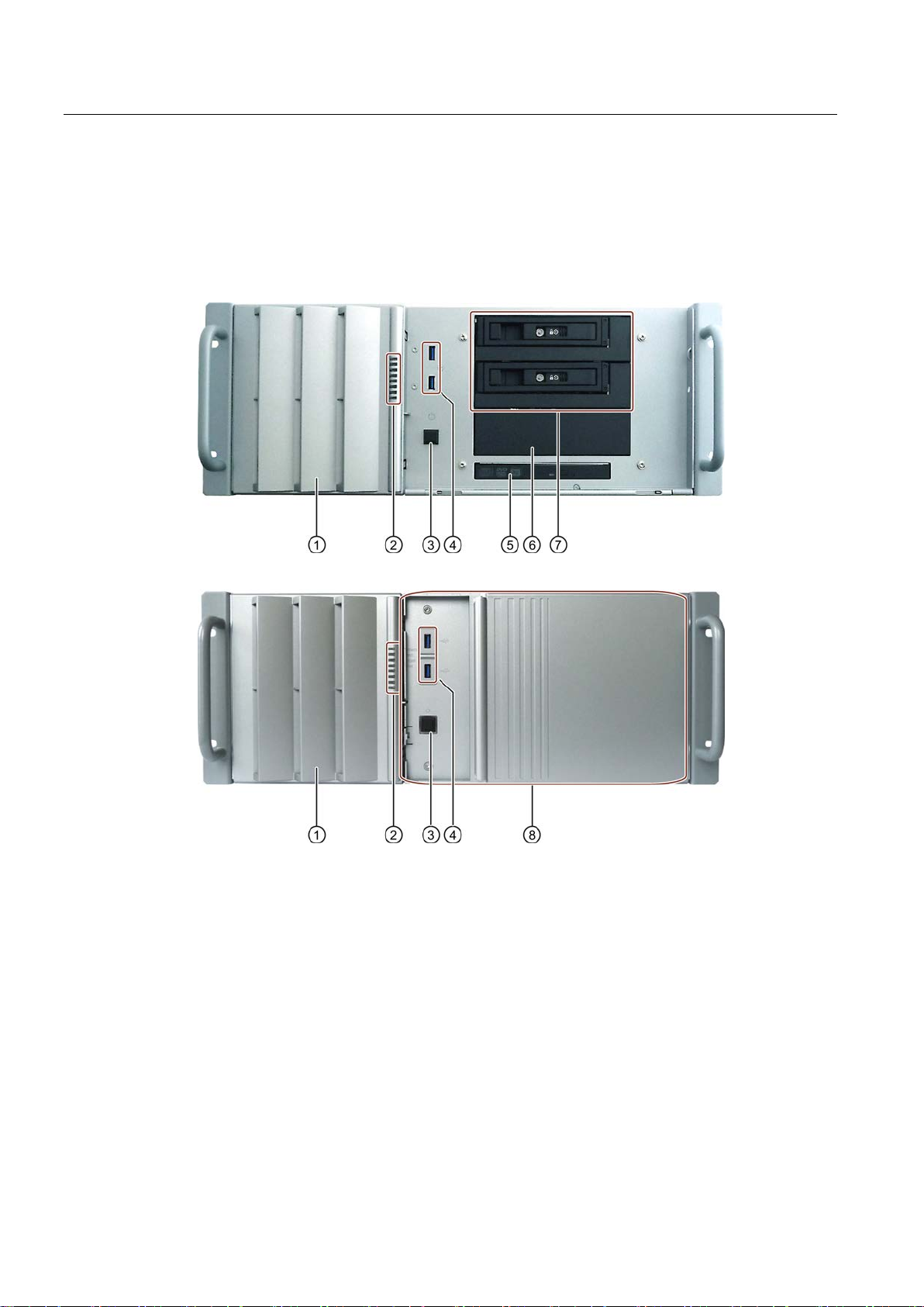
Device front with open front door
SIMATIC IPC547E
SIMATIC IPC547E with short enclosure
①
Fan cover
Fan cover with openings
②
Status displays
See chapter "
③
On/off button
See chapter "
④
2 × USB 3.0
Connections for USB devices, backward compatible with
USB 2.0/1.1
⑤
Optical drive
DVD burner drive
⑥
Mounting locations
For removable drive bays with drives (HDD or SSD) or for
5.25" drives
⑦
1 to 4 removable
bays
Depending on configuration, 1
drives (HDD or SSD)
⑧
Front panel
Is removed for taking out and installing the internal hard disk
drives
1.2 Device configuration
SIMATIC IPC547E
14 Operating Instructions, 02/2014, A5E32317120-AB
drive
for ventilation of the device
Status displays (Page 20)."
Operator controls (Page 18)."
to 4 removable drive bays with
Overview
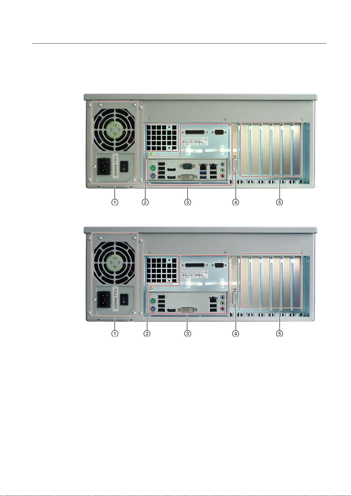
Rear of the device
SIMATIC IPC547E
SIMATIC IPC547E with short enclosure
①
Power supply
See section "
supply connection
②
Air outlet
③
Interfaces
See chapter "
④
Dual
card
DMS59 connection of optional dual
⑤
Expansion card slots
•
•
•
1.2 Device configuration
-head graphics
Interfaces and connections (Page 16)", power
Interfaces and connections (Page 16)."
-head graphics card
SIMATIC IPC547E
Operating Instructions, 02/2014, A5E32317120-AB
4 × PCI
2 × PCIe x16
1 × PCIe x8
15
Overview
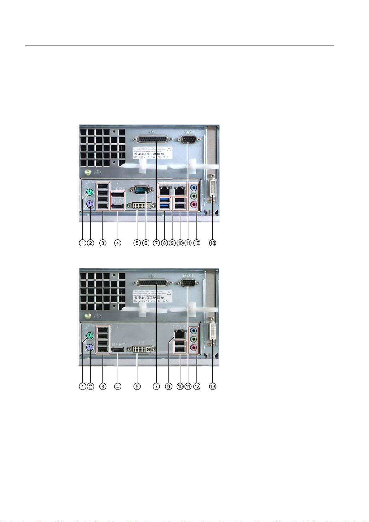
1.3
Interfaces and connections
Interfaces
SIMATIC IPC547E
SIMATIC IPC547E with short enclosure
①
Mouse
Connection for a PS/2 mouse
②
Keyboard
Connection for a PS/2 keyboard
③
4 x USB 2.0
Connections for USB devices
1.3 Interfaces and connections
SIMATIC IPC547E
16 Operating Instructions, 02/2014, A5E32317120-AB

Overview
④
DPP1
DPP2
or
DPP1
Connection for monitors with DisplayPort in
⑤
DVI
Connection for CRT or LCD monitor with DVI interface, VGA via
DVI/VGA adapter (optional)
⑥
COM1
Serial interface 1 (V.24), 9
⑦
LPT Parallel interface, 25
⑧
2 x USB 3.0
Connections for USB devices, backward compatible with USB
2.0/1.1
⑨
LAN
LAN
or
LAN1
RJ45 Ethernet connections for 10/100/1000 Mbps
LAN 1 is iAMT capable (for SIMATIC IPC547E only)
⑩
2 x USB 2.0
Connections for USB devices
⑪
COM2
Serial interface 2 (V.24), 9
⑫
Line in (blue)
Line out (green)
Microphone (pink)
Connection for analog audio source, 3.5
Connection for active speakers or headset, 3.5
Connection for microphone, 3.5 mm phono jack
⑬
Dual
card
DMS59 connection of optional dual
1
The Ethernet interfaces are numbered on the enclosure to identify them clearly.
The numbering by the operating system may deviate from this.
Dual-head adapter for connection of two monitors to the optional graphics card
②
③
1.3 Interfaces and connections
-I
1
2
-pin D-sub socket
-pin (optional)
-pin D-sub socket (optional)
terface
1)
mm phono jack
mm phono jack
-head graphics
-head graphics card
DMS59 connector DMS59 connection
①
DVI-I connector DVI-I connections
VGA connector VGA connections
SIMATIC IPC547E
Operating Instructions, 02/2014, A5E32317120-AB
17
Overview
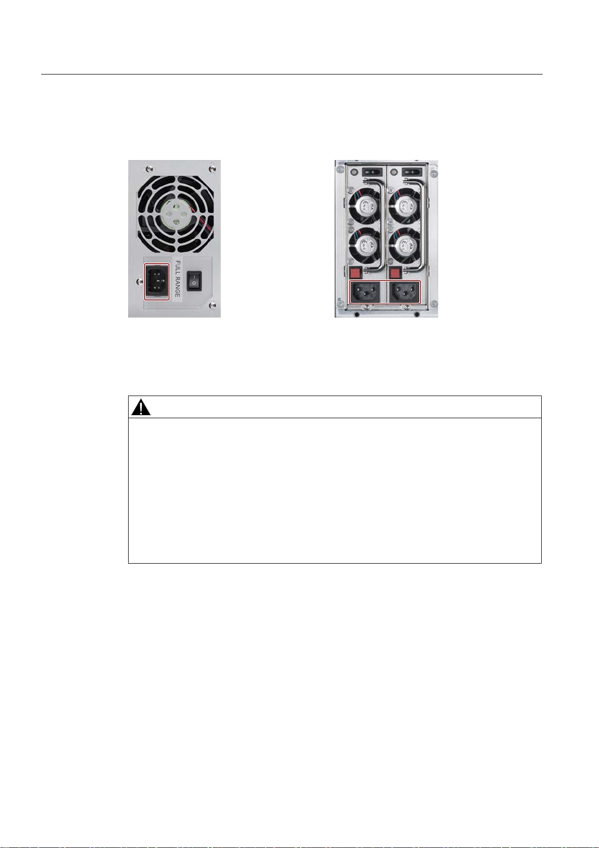
Power supply connections
1.4
Operator controls
WARNING
Risk of electric shock
Take additional precautions, for example, by using a circuit breaker.
1.4 Operator controls
The following figure shows the connections for the power supply for devices with single or
redundant power supply.
The on/off button and on/off switch do not fully disconnect the device from the mains. If the
device is switched off with the on/off switch, there remains a risk of electric shock and fire
hazard, for example, if the device or connection cables are damaged or if the device is
used improperly.
Always fully disconnect the device from the mains voltage as follows before performing
work on the device or when the device will not be used over an extended period of time:
• Pull the power plug on the rear of the device.
• For control cabinet mounting:
Read the information in section "Switching off the device (Page 53)".
SIMATIC IPC547E
18 Operating Instructions, 02/2014, A5E32317120-AB
Overview
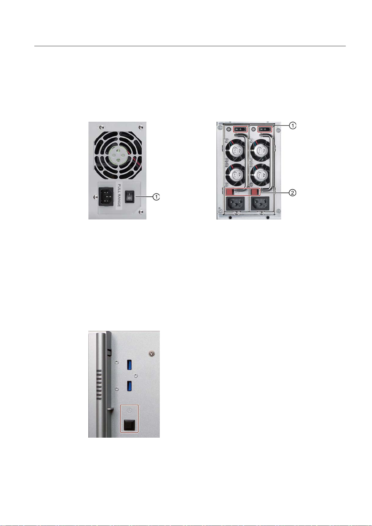
On/Off switch and alarm reset button
①
On/Off switch
②
Alarm reset button can be used to switch off the warning signal
On/off button
1.4 Operator controls
The following figures show the location of the on/off switch on the rear of the device for
devices with simple or redundant power supply.
The alarm reset button is only available for devices with redundant power supply.
The On/off button is located on the front of the device behind the front door and is used to
start and shut down the operating system.
You can find additional information in the chapters "Switching on the device (Page 47)" and
"Switching off the device (Page 53)."
SIMATIC IPC547E
Operating Instructions, 02/2014, A5E32317120-AB
19
Overview
1.5
Status displays
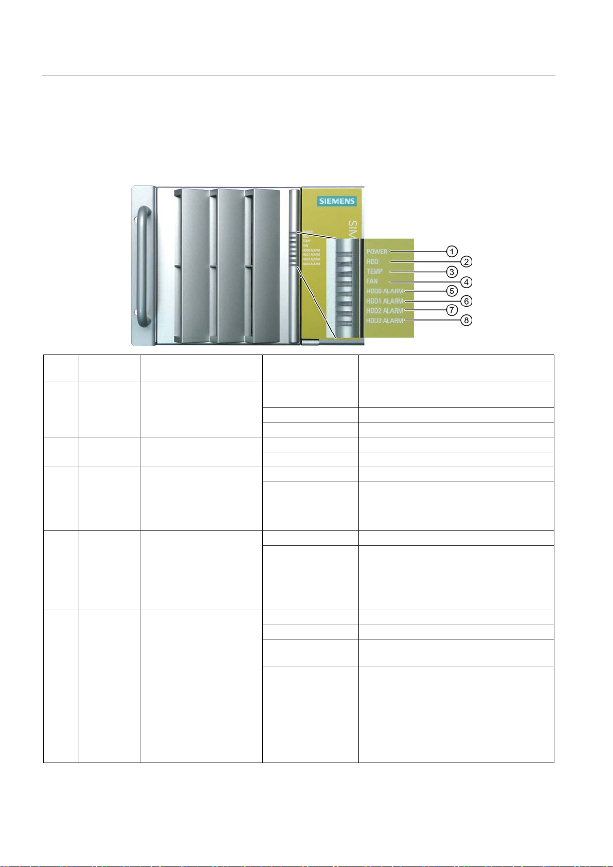
Front status displays
Item Status
display
Meaning
LED Description
the mains
GREEN flashing
Windows is in Standby mode
GREEN
PC in operation
②
OFF
No access
GREEN
Access
③
④
OFF
No error
OFF
RAID is OK
A RED LED is lit up
The associated drive is not OK
flashing
(Page 52)".
1.5 Status displays
The status displays integrated in the front door provide information on the status of the
device components listed in the following table.
①
⑤
⑥
⑦
⑧
POWER Operating mode of the PC OFF
HDD Access to hard disk
TEMP Temperature status OFF No error
RED flashing Possible causes:
FAN Fan status
RED flashing Possible causes:
HDD0 Alarm
HDD1 Alarm
HDD2 Alarm
HDD3 Alarm
HDD alarm in connection
with RAID and monitoring
software
All RED LEDs are
All RED LEDs are lit
up
Hibernate, switched off or disconnected from
• CPU temperature is critical
• Device temperature is critical
• CPU heat sink fan fault
• Enclosure fan fault
• Power supply fan fault
RAID synchronized
RAID is not OK
The faulty drive could not be localized by the
monitoring software. It may be possible to
detect the defective drive with the RAID
software, see chapter "RAID1 system
(Page 51)", "RAID5 system (Page 52)" or
"RAID system with hot spare drive
SIMATIC IPC547E
20 Operating Instructions, 02/2014, A5E32317120-AB
Overview
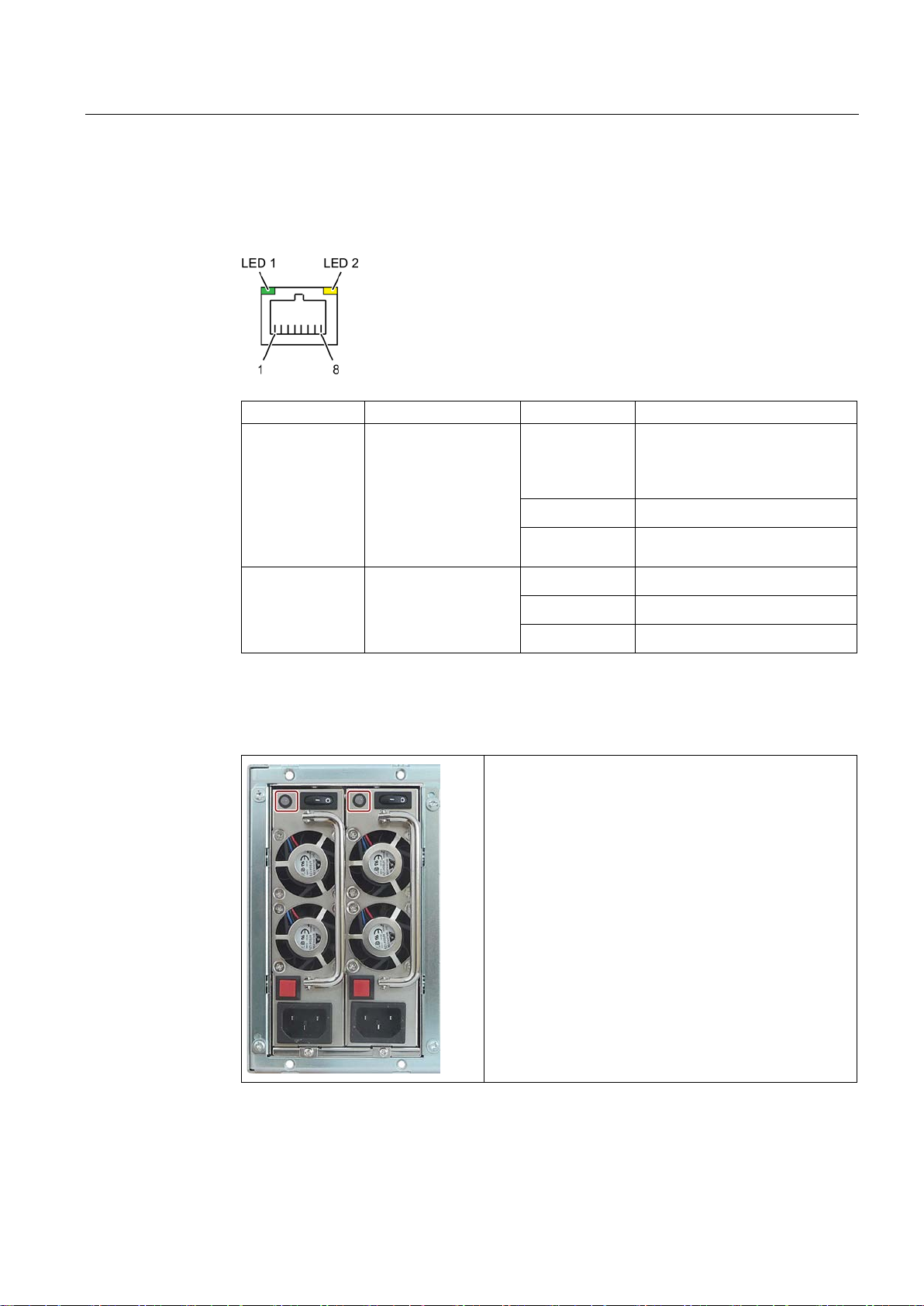
Rear status displays
Status display
Meaning
Status
Meaning of the status
flashing
operating system may deviate from this.
signal permanently. Redundancy is in effect when both
1.5 Status displays
The following status displays are located on the rear of the device:
● LEDs of the Ethernet interface
LED 1 1 Connection status OFF
• No cable connected
• Cable disabled
• Interface disabled
GREEN
GREEN,
LED 2 1 Data transmission rate OFF
GREEN
YELLOW
1
For unique labeling, the Ethernet ports are numbered on the enclosure. The numbering by the
• Active cable connected
• Data transfer active
• 10 Mbps
• 100 Mbps
• 1000 Mbps
● Redundant power supply
The "Power" LED has the following meaning:
• Lights up green:
Power supply module is operating.
If there is no redundancy, you will hear an acoustic
power supply modules are operating.
• Not lit:
SIMATIC IPC547E
Operating Instructions, 02/2014, A5E32317120-AB
Power supply module is out of service.
21

Overview
1.5 Status displays
SIMATIC IPC547E
22 Operating Instructions, 02/2014, A5E32317120-AB

2
2.1
General safety instructions
Fully disconnecting the device from mains voltage
WARNING
Risk of fire and electric shock
Devices in the control cabinet
WARNING
Life-threatening voltages are present with an open control cabinet
The on/off button and on/off switch do not fully disconnect the device from the mains. If the
device is switched off with the on/off switch, there remains a risk of electric shock and fire
hazard, for example, if the device or connection cables are damaged or if the device is
used improperly.
Always fully disconnect the device from the mains voltage as follows before performing
work on the device or when the device will not be used over an extended period of time.
• If the device was not mounted in a control cabinet: Shut down the operating system and
pull the power plug on the rear of the device.
• If the device was mounted in a control cabinet: Shut down the operating system and
switch the AC circuit breaker to "Off".
• Properly connect the device to a protective conductor.
When you open the control cabinet, some areas or components may be carrying lifethreatening voltages.
If you touch these areas or components, you may be killed by electric shock.
Switch off the power supply to the cabinet before opening it.
SIMATIC IPC547E
Operating Instructions, 02/2014, A5E32317120-AB
23

Safety instructions
System expansions
NOTICE
Damage to the device, machine or plant due to device and system expansions
CAUTION
Fire hazard due to overheating of the device
2.1 General safety instructions
Device and system expansions may contain faults and affect the entire device, machine or
plant.
Device and system expansions may violate safety rules and regulations regarding radio
interference suppression. If you install or replace device or system expansions and damage
your device, the warranty is voided.
Note the following:
• Only install device or system expansions designed for this device. Contact your
technical support team or the point of sale to find out which device and system
expansions are suitable for installation.
• Please observe the information on electromagnetic compatibility in the technical
specifications.
Expansion cards generate additional heat. The device can overheat or cause a fire.
• Observe the safety and installation instructions for the expansion cards.
• If necessary, install the device in an enclosure that meets the requirements of
paragraphs 4.6 and 4.7.3 of the standards EN 60950-1:2006 and IEC/UL/EN/DIN-EN
60950-1.
SIMATIC IPC547E
24 Operating Instructions, 02/2014, A5E32317120-AB

Safety instructions
Battery
WARNING
Risk of explosion and release of harmful substances
High frequency radiation
NOTICE
Unintentional operating situations
2.1 General safety instructions
Improper handling of lithium batteries can result in an explosion of the batteries.
Explosion of lithium batteries and the released pollutants can cause serious physical injury.
Damaged batteries jeopardize the function of the device.
Note the following when handling lithium batteries:
• Replace used batteries in good time; see the section "Replacing the backup battery" in
the section "Device maintenance and repair".
• Replace the lithium battery only with an identical battery or types recommended by the
manufacturer (order no.: A5E00369854).
• Do not throw lithium batteries into fire, do not solder on the cell body, do not recharge,
do not open, do not short-circuit, do not reverse polarity, do not heat above 100°C and
protect from direct sunlight, moisture and condensation.
High frequency radiation, e.g. from a cellular phone, may interfere with device functions and
can cause malfunctions resulting in personal injury or material damage.
Avoid high-frequency radiation:
• Remove radiation sources from the environment of the device.
• Switch off radiating devices.
• Reduce the radio output of radiating devices.
• Please observe the information on electromagnetic compatibility in the technical
specifications.
SIMATIC IPC547E
Operating Instructions, 02/2014, A5E32317120-AB
25

Safety instructions
ESD directive
NOTICE
Electrostatic sensitive devices (ESD)
Industrial Security
2.1 General safety instructions
Electrostatic sensitive devices can be labeled with an appropriate symbol.
When you touch electrostatic sensitive components, you can destroy them through voltages
that are far below the human perception threshold.
If you work with components that can be destroyed by electrostatic discharge, observe the
ESD directive in the technical specifications.
Siemens offers products and solutions with Industrial Security functions that support the safe
operation of equipment, solutions, machines, devices and/or networks. They are important
components in a comprehensive Industrial Security concept. As a result the products and
solutions from Siemens are constantly evolving. Siemens recommends obtaining regular
information regarding product updates.
For safe operation of Siemens products and solutions appropriate protective measures (e.g.,
cell protection concept) must be taken and each component must be integrated in a
comprehensive Industrial Security concept, which corresponds with the current state of
technology. The products of other manufacturers need to be taken into consideration if they
are also used. You can find addition information on Industrial Security under
(http://www.siemens.com/industrialsecurity
).
Sign up for our product-specific newsletter to receive the latest information on product
updates. For more information, see under (http://www.siemens.de/automation/csi_en_WW
).
SIMATIC IPC547E
26 Operating Instructions, 02/2014, A5E32317120-AB

Safety instructions
2.2
Headphones
CAUTION
Impaired hearing due to excessive sound pressure
2.3
Access protection
CAUTION
Protection against access by unauthorized persons
2.2 Headphones
The setting of the volume and the equalizer can increase the sound pressure in the
headphones. Other factors not mentioned by the manufacturer can also influence the
sound pressure, for example, the operating system, equalizer software, firmware and
driver.
Excessive sound pressure from headphones can result in impaired hearing or even loss of
hearing.
Set the volume control and equalizer to the lowest value before you put on the
headphones. Keep checking the volume control setting. Only use headphones and
software approved by the manufacturer.
An unauthorized user can operate the device incorrectly and bypass logon by restarting the
device.
Operator actions by unauthorized persons jeopardize operational reliability.
Take the following safety precautions:
• Lock the front door and the removable drive bay.
• Do not use keyboards with an on/off button (Power button).
• If the device has a on/off button, assign the parameters of the function of the on/off
button to meet your requirements under Windows. You can find the settings in the
"Power Options" menu.
SIMATIC IPC547E
Operating Instructions, 02/2014, A5E32317120-AB
27

Safety instructions
2.4
Notes on use
NOTICE
Possible functional restrictions in case of non-validated plant operation
NOTICE
2.4 Notes on use
The device is tested and certified on the basis of the technical standards. In rare cases,
functional restrictions can occur during plant operation.
Validate the correct functioning of the plant to avoid functional restrictions.
Rack-mount instructions
A) Elevated Operating Ambient - If installed in a closed or multi-unit rack, the operating
ambient temperature of the rack environment may be greater than the room ambient.
Therefore consideration should be given to installing the equipment in an environment
compatible with the maximum ambient temperature (Tma) specified by the manufacturer.
B) Reduced Air Flow - Installation of the equipment in a rack should be such that the
amount of air flow required for safe operation of the equipment is not compromised.
C) Mechanical Loading - Mounting of the equipment in the rack should be such that a
hazardous condition is not achieved due to uneven mechanical loading.
D) Circuit Overloading - Consideration should be given to the connection of the equipment
to the supply circuit and the effect that overloading of the circuits might have on overcurrent
protection and supply wiring. Appropriate consideration of equipment nameplate ratings
should be used when addressing this concern.
E) Reliable Earthing - Reliable earthing of rack-mounted equipment should be maintained.
Particular attention should be given to supply connections other than direct connections to
the branch circuit (e. g. use of power strips).
SIMATIC IPC547E
28 Operating Instructions, 02/2014, A5E32317120-AB

Safety instructions
NOTICE
Ambient conditions
Note
Use in an industrial environment without additional protective measures
This device was designed for use in a normal industrial environment according to
IEC
2.4 Notes on use
Ambient conditions for which the device is not suitable can cause faults or damage the
device.
Note the following:
• Operate the device only in closed rooms. Failure to comply nullifies the warranty.
• Operate the device only in accordance with the ambient conditions specified in the
technical specifications.
• Protect the device against dust, moisture and heat.
• Do not expose the device to direct sunlight or other strong sources of light.
• Without additional measures, such as a supply of clean air, the device may not be used
in locations with harsh operating conditions caused by acidic vapors or gases.
• Observe the permitted mounting positions of the device.
• Do not obstruct the venting slots of the device.
60721-3-3.
SIMATIC IPC547E
Operating Instructions, 02/2014, A5E32317120-AB
29

Safety instructions
2.4 Notes on use
SIMATIC IPC547E
30 Operating Instructions, 02/2014, A5E32317120-AB
 Loading...