

Siemens Simatic IPC527G Operating Instructions Manual

SIMATIC IPC527GSIMATIC IPC527G
SIMATIC
Industrial PC
SIMATIC IPC527G
Operating Instructions
03/2019
A5E45491226
Preface
Overview
1
Safety instructions
2
Installing and connecting the
device
3
Commissioning the device
and device functions
4
Expanding and assigning
parameters to the device
5
Maintaining and repairing the
device
6
Technical specifications
7
Appendix Motherboard
A
Technical support
B
Markings and symbols
C
List of abbreviations
D
-AA

Siemens AG
Division Digital Factory
Postfach 48 48
90026 NÜRNBERG
GERMANY
A5E45491226-AA
Ⓟ
Copyright © Siemens AG 2019.
All rights reserved
Legal information
Warning notice system
DANGER
indicates that death or severe personal injury will result if proper precautions are not taken.
WARNING
indicates that death or severe personal injury may result if proper precautions are not taken.
CAUTION
indicates that minor personal injury can result if proper precautions are not taken.
NOTICE
indicates that property damage can result if proper precautions are not taken.
Qualified Personnel
personnel qualified
Proper use of Siemens products
WARNING
Siemens products may only be used for the applications described in the catalog and in the relevant technical
ambient conditions must be complied with. The information in the relevant documentation must be observed.
Trademarks
Disclaimer of Liability
This manual contains notices you have to observe in order to ensure your personal safety, as well as to prevent
damage to property. The notices referring to your personal safety are highlighted in the manual by a safety alert
symbol, notices referring only to property damage have no safety alert symbol. These notices shown below are
graded according to the degree of danger.
If more than one degree of danger is present, the warning notice representing the highest degree of danger will
be used. A notice warning of injury to persons with a safety alert symbol may also include a warning relating to
property damage.
The product/system described in this documentation may be operated only by
task in accordance with the relevant documentation, in particular its warning notices and safety instructions.
Qualified personnel are those who, based on their training and experience, are capable of identifying risks and
avoiding potential hazards when working with these products/systems.
Note the following:
documentation. If products and components from other manufacturers are used, these must be recommended
or approved by Siemens. Proper transport, storage, installation, assembly, commissioning, operation and
maintenance are required to ensure that the products operate safely and without any problems. The permissible
All names identified by ® are registered trademarks of Siemens AG. The remaining trademarks in this publication
may be trademarks whose use by third parties for their own purposes could violate the rights of the owner.
We have reviewed the contents of this publication to ensure consistency with the hardware and software
described. Since variance cannot be precluded entirely, we cannot guarantee full consistency. However, the
information in this publication is reviewed regularly and any necessary corrections are included in subsequent
editions.
for the specific
04/2019 Subject to change

Preface
Basic knowledge requirements
Validity of the operating instructions
Scope of this documentation
Conventions
History
Edition
Comment
03/2019
First edition
These operating instructions contain all the information you need for commissioning and
operation of the SIMATIC IPC527G.
It is intended both for programming and testing personnel who commission the device and
connect it with other units (automation systems, programming devices), as well as for service
and maintenance personnel who install add-ons or carry out fault/error analyses.
A solid background in personal computers and Microsoft operating systems is required to
understand this manual. General knowledge in the field automation control engineering is
recommended.
These operating instructions are valid for all versions of the SIMATIC IPC527G.
The documentation for the SIMATIC IPC527G consists of:
● Quick Install Guide SIMATIC IPC527G
● SIMATIC IPC527G Operating Instructions in English and Chinese
The PDF version of the documentation is supplied with the device on the
"Documentation and Drivers" USB stick.
The terms "PC" and "device" are sometimes used to refer to the SIMATIC IPC527G in this
documentation.
In these operating instructions, the abbreviation "Windows 7" denotes the term
"Windows 7 Ultimate".
The following editions of these operating instructions have been published:
SIMATIC IPC527G
Operating Instructions, 03/2019, A5E45491226-AA
3

Table of contents
Preface ................................................................................................................................................... 3
1 Overview ................................................................................................................................................ 7
2 Safety instructions................................................................................................................................. 13
3 Installing and connecting the device ...................................................................................................... 17
4 Commissioning the device and device functions .................................................................................... 32
5 Expanding and assigning parameters to the device ............................................................................... 36
1.1 Product description .................................................................................................................. 7
1.1.1 Configuration plan .................................................................................................................... 8
1.2 Structure of the devices ......................................................................................................... 10
1.2.1 Views of the basic device ....................................................................................................... 10
1.2.2 Interfaces of the basic device ................................................................................................ 11
1.2.3 Status displays ....................................................................................................................... 12
2.1 Security information ............................................................................................................... 13
2.2 Data protection ....................................................................................................................... 13
2.3 General safety instructions .................................................................................................... 14
2.4 Notes on use .......................................................................................................................... 16
3.1 Preparing for installation ........................................................................................................ 17
3.1.1 Checking the delivery package .............................................................................................. 17
3.1.2 Identification data of the device ............................................................................................. 18
3.1.3 Permitted mounting positions ................................................................................................. 20
3.2 Mounting the device ............................................................................................................... 21
3.2.1 Mounting instructions ............................................................................................................. 21
3.2.2 Desk mounting ....................................................................................................................... 23
3.2.3 Wall mounting ........................................................................................................................ 23
3.2.4 Book mounting ....................................................................................................................... 25
3.2.5 Tower mounting ..................................................................................................................... 26
3.3 Connecting the device ........................................................................................................... 27
3.3.1 Notes on connecting .............................................................................................................. 27
3.3.2 Connecting the function earth ................................................................................................ 27
3.3.3 Connecting the power supply ................................................................................................. 29
3.3.4 Connect device to networks ................................................................................................... 31
4.1 General information on commissioning ................................................................................. 32
4.2 Initial commissioning .............................................................................................................. 32
4.3 Switching off the device ......................................................................................................... 33
4.4 Windows Security Center ....................................................................................................... 35
5.1 Open the device ..................................................................................................................... 36
SIMATIC IPC527G
4 Operating Instructions, 03/2019, A5E45491226-AA

Table of contents
6 Maintaining and repairing the device ..................................................................................................... 45
7 Technical specifications ........................................................................................................................ 55
5.2 Extension card ........................................................................................................................ 38
5.3 Riser card ................................................................................................................................ 40
5.4 Memory module ...................................................................................................................... 41
5.5 Disk drive ................................................................................................................................ 43
6.1 Maintenance ........................................................................................................................... 45
6.2 Repair information ................................................................................................................... 45
6.3 Installing and removing hardware ........................................................................................... 46
6.3.1 Replacing the device fan ........................................................................................................ 46
6.3.2 Replacing the backup battery ................................................................................................. 48
6.4 Installing the software ............................................................................................................. 51
6.4.1 Installing the drivers ................................................................................................................ 51
6.5 Recycling and disposal ........................................................................................................... 54
7.1 Certificates and approvals ...................................................................................................... 55
7.2 Directives and declarations ..................................................................................................... 58
7.2.1 Electromagnetic compatibility, Industrial and Residential Areas ............................................ 58
7.2.2 ESD guideline ......................................................................................................................... 58
7.3 Dimension drawings ................................................................................................................ 60
7.4 Technical data ......................................................................................................................... 62
7.4.1 General technical specifications ............................................................................................. 62
7.4.2 Environmental conditions ........................................................................................................ 65
7.4.3 Power demand of the components ......................................................................................... 66
7.4.4 Basic power supply ................................................................................................................. 66
7.5 Hardware descriptions ............................................................................................................ 67
7.5.1 Technical features of the motherboard ................................................................................... 67
7.5.2 External interfaces .................................................................................................................. 67
7.5.2.1 Overview of interfaces ............................................................................................................ 67
7.5.2.2 Serial interface ........................................................................................................................ 68
7.5.2.3 USB 2.0 port ........................................................................................................................... 69
7.5.2.4 USB 3.0 port ........................................................................................................................... 69
7.5.2.5 DisplayPort .............................................................................................................................. 69
7.5.2.6 Ethernet port ........................................................................................................................... 70
7.5.2.7 DIO port .................................................................................................................................. 71
7.5.3 Internal interfaces ................................................................................................................... 72
7.5.3.1 Overview of internal interfaces ............................................................................................... 72
7.5.3.2 M.2 interface ........................................................................................................................... 73
7.5.4 Currently allocated system resources ..................................................................................... 74
7.6 BIOS description ..................................................................................................................... 74
7.6.1 BIOS getting started ................................................................................................................ 74
7.6.2 Main menu .............................................................................................................................. 77
7.6.3 Advanced menu ...................................................................................................................... 80
7.6.4 Hardware Monitor menu ......................................................................................................... 87
7.6.5 Boot menu ............................................................................................................................... 88
SIMATIC IPC527G
Operating Instructions, 03/2019, A5E45491226-AA
5

Table of contents
A Appendix Motherboard .......................................................................................................................... 92
B Technical support................................................................................................................................. 104
C Markings and symbols ......................................................................................................................... 107
D List of abbreviations ............................................................................................................................. 110
Glossary .............................................................................................................................................. 114
Index ................................................................................................................................................... 122
7.6.6 Save & Exit menu................................................................................................................... 90
A.1 Jumpers ................................................................................................................................. 92
A.2 Internal Connector ................................................................................................................. 96
A.2.1 Intel® H110 Serial ATA 6.0Gb/s connectors (SATA6G_1~2) ................................................ 96
A.2.2 CPU and chassis fan connectors (CPU_FAN, CHA_FAN) .................................................... 97
A.2.3 ATX power connectors (EATXPWR, ATX12V, ATX_PWR) .................................................. 98
A.2.4 Digital I/O connector (DIO) ..................................................................................................... 99
A.2.5 Serial port connectors (COM3, COM4) ................................................................................ 100
A.2.6 M.2 B Key slot ...................................................................................................................... 101
A.2.7 USB 2.0 connectors (USB56, USB78, USB9) ..................................................................... 102
A.2.8 System panel connector (F_PANEL) ................................................................................... 103
B.1 Service and support ............................................................................................................. 104
B.2 Troubleshooting ................................................................................................................... 105
B.3 Notes on the use of third-party modules .............................................................................. 106
C.1 Overview .............................................................................................................................. 107
C.2 Safety ................................................................................................................................... 107
C.3 Operator controls ................................................................................................................. 107
C.4 Certificates, approvals and markings ................................................................................... 108
C.5 Interfaces ............................................................................................................................. 109
SIMATIC IPC527G
6 Operating Instructions, 03/2019, A5E45491226-AA
1
1.1
Product description
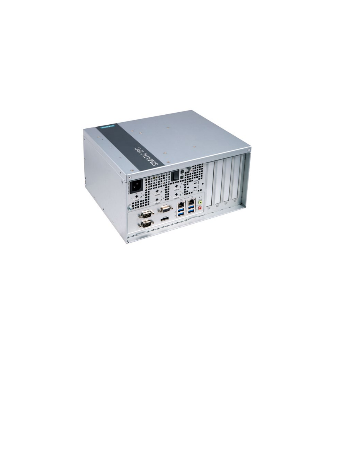
SIMATIC IPC527G is a compact PC with industrial functionality.
● Compact design
● Expandability (expansion card slots)
● Scalability
● Rugged
● Various interfaces
SIMATIC IPC527G
Operating Instructions, 03/2019, A5E45491226-AA
7

Overview
1.1.1
Configuration plan
.
Drives and storage media
optional
M.2 Solid State Driver
M.2 2242 Key B slot
USB stick
Can be connected externally through USB port and internally
Interfaces
USB (internal)
1 x USB 2.0 vertical (500 mA) for internal USB stick/dongle
1.1 Product description
Mounting The device supports the following four mounting types:
Chipset
Processor
Main memory Memory expansion up to 16 GB with the following memory modules (without ECC), support
Possible of extendability
Graphics
Power supply 100 V AC to 240 V AC (-10%, +10%)
• Desk mounting
• Wall mounting
• Book mounting
• Tower mounting
• Intel® H110
• Intel® Pentium® Processor G4400 (3M Cache, 3.30 GHz)
• Intel® Core™ i5-6500 Processor (6M Cache, up to 3.60 GHz)
• Intel® Core™ i7-6700 Processor (8M Cache, up to 4.00 GHz)
of 32 GB (2 × 16GB) possible:
• 4G DDR4 SDRAM
• 8G DDR4 SDRAM
• 16G DDR4 SDRAM
• 1 × PCIe ×16 slot;
• 1 × PCIe ×16 slot, 1 × PCIe ×1 slot, 2 × PCI slot (with riser card)
• Integrated Graphic Controller
• 1 × VGA(DB-15) + 1 × DP(DDI)
• VGA support max to 1920 × 1200 pixels
• DP support max to 4K
Hard Disk Drive (HDD),
Solid State Drive (SSD),
optional
Ethernet
COM
USB (external)
SIMATIC IPC527G
1 TB, 2.5" HDD SATA
• 128 GB, 2.5" SSD SATA
• 256 GB, 2.5" SSD SATA*
• 512 GB, 2.5" SSD SATA*
• 2 × RJ45 Ethernet 10/100/1000 Mbps
• 2 × RJ45 Ethernet 10/100/1000 Mbps +1 × RJ45 Ethernet 10/100/1000 Mbp (1 PCIe slot
occupied)
• 2 × RS232 /RS422 /RS485
• 2 × RS232 /RS422 /RS485 + 2 × RS232
• 4 × USB 3.0 (900mA)
• 4 × USB 3.0 (900mA)+ 2 × USB 2.0 (500mA)
8 Operating Instructions, 03/2019, A5E45491226-AA

Overview
VGA
Connection of an analog monitor
DP
Connection of a digital monitor
Keyboard, mouse
Connection through USB port
Operating systems
1
MUI: Multi
stick. You can install them according to your request.
* The configurations
refer to the Technical data (Page 62).
1.1 Product description
DIO (Digital Input Output)
Operation Systems
• Without
• DB9 connector, Digital Input (5V TTL) and Output (5V 12mA)
• Without
1
• Windows 7 Ultimate 32-bit (MUI), SP1
• Windows 7 Ultimate 64-bit (MUI), SP1
1
-language user interface; More language packages are available on the USB
are not released in the current version. For the detailed configuration,
SIMATIC IPC527G
Operating Instructions, 03/2019, A5E45491226-AA
9
Overview
1.2
Structure of the devices
1.2.1
Views of the basic device
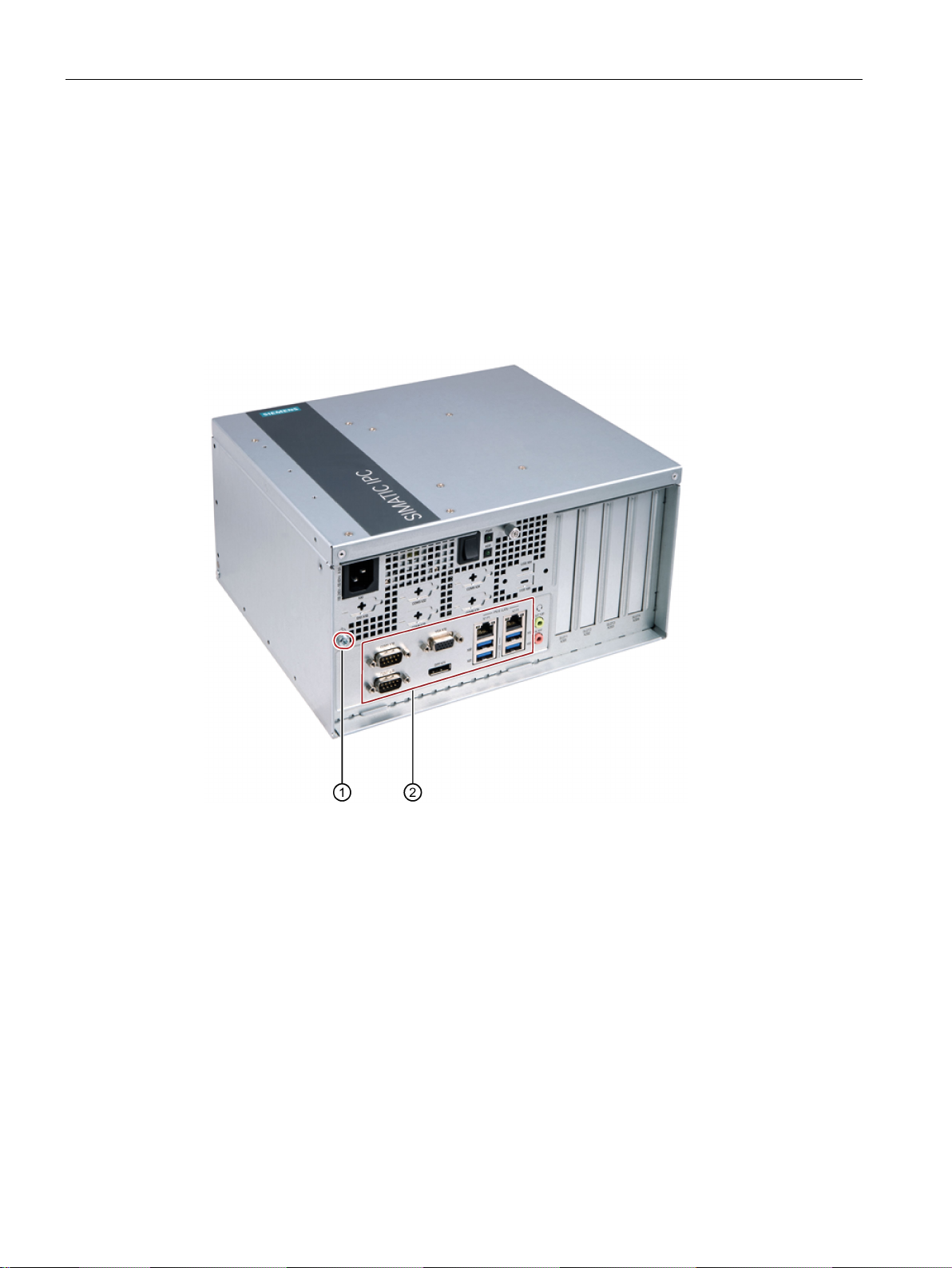
Front view
①
Function earth
②
Ports
1.2 Structure of the devices
The following picture shows the front view of IPC527G.
SIMATIC IPC527G
10 Operating Instructions, 03/2019, A5E45491226-AA
Overview
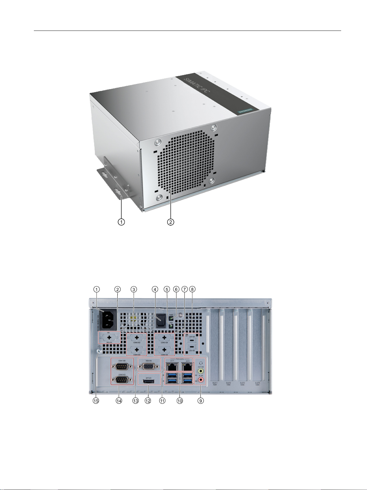
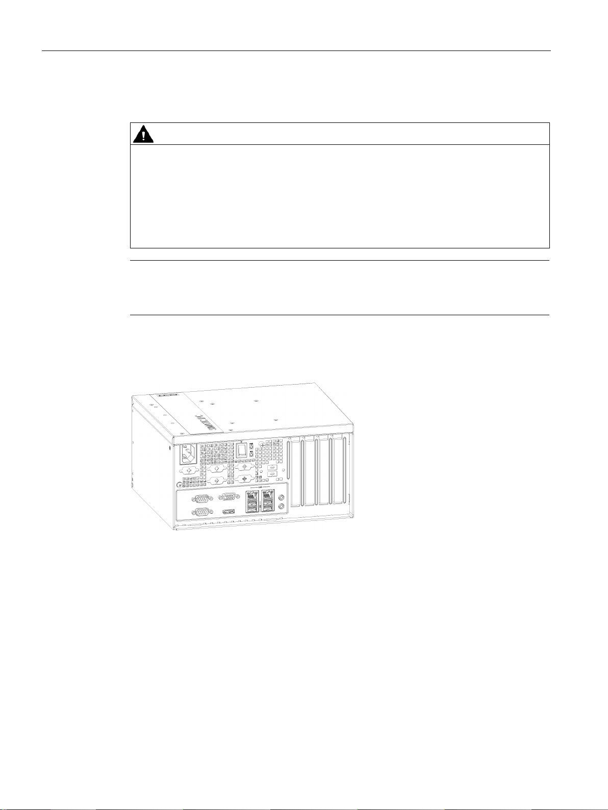
Rear view
①
Mounting bracket
②
Air inlet
1.2.2
Interfaces of the basic device
1.2 Structure of the devices
SIMATIC IPC527G
Operating Instructions, 03/2019, A5E45491226-AA
11
Overview
①
100
Power supply connection
②
DIO X10
DIO port
③
COM3/4 X32/X33
Serial interface, 9
④
Power button
Switch of the power supply
⑤
HDD LED
Display for hard disk access
⑥
PWR
PC operating status display
⑦
COM5/6 X34/X35
Reserved
⑧
USB X64 and USB X65
USB 2.0, high current
⑨
Line Out port (lime) X90
Connection for headphone or speaker
Microphone port (pink) X91
Connection for microphone
⑩
4 × USB X60/X61/X62/X63
USB
⑪
2 × Ethernet X1P1/X2P1
RJ45 Ethernet connection for 10/100/1000 Mbps
⑫
DPP X71
DisplayPort connection for digital monitor
⑬
VGA X70
Connection for monitor with Video Graphics Adapter
(VGA) interface
⑭
COM1/2 X30/X31
Ser
⑮
Function earth
Connection for function earth
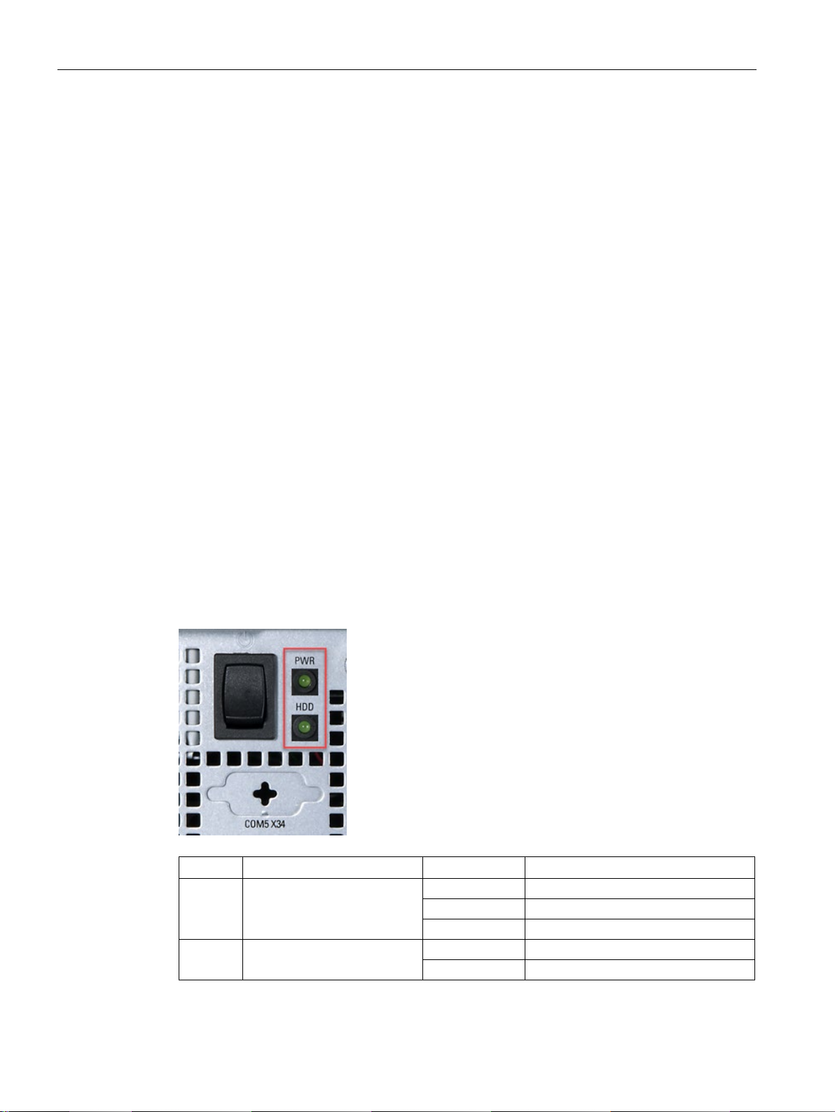
1.2.3
Status displays
Display
Meaning
LED
Description
Off
Hibernate, switched off or unplugged
Green
PC is in operation.
Green flashing
standby
Off
No accessing
Green flashing
Accessing data
1.2 Structure of the devices
-240 VAC X80
LED
3.1 Gen 1 (up to 5Gbps) ports
ial interface, 9-pin RS232 /RS422 /RS485
-pin RS232
PWR PC operating status display
HDD Display for hard disk access
SIMATIC IPC527G
12 Operating Instructions, 03/2019, A5E45491226-AA

2
2.1
Security information
2.2
Data protection
Siemens provides products and solutions with industrial security functions that support the
secure operation of plants, systems, machines and networks.
In order to protect plants, systems, machines and networks against cyber threats, it is
necessary to implement – and continuously maintain – a holistic, state-of-the-art industrial
security concept. Siemens’ products and solutions constitute one element of such a concept.
Customers are responsible for preventing unauthorized access to their plants, systems,
machines and networks. Such systems, machines and components should only be
connected to an enterprise network or the internet if and to the extent such a connection is
necessary and only when appropriate security measures (e.g. firewalls and/or network
segmentation) are in place.
For additional information on industrial security measures that can be implemented, please
visit (https://www.siemens.com/industrialsecurity).
Siemens' products and solutions undergo continuous development to make them more
secure. Siemens strongly recommends that product updates are applied as soon as they are
available and that the latest product versions are used. Use of product versions that are no
longer supported, and failure to apply the latest updates may increase customers' exposure
to cyber threats.
To stay informed about product updates, subscribe to the Siemens Industrial Security RSS
Feed visit (https://www.siemens.com/industrialsecurity).
Siemens observes the data protection guidelines, especially the requirements regarding data
minimization (privacy by design). This means the following for this SIMATIC product: The
product does not process / save any personal information, but only technical functional data
(e.g. time stamps). If the user links this data to other data (e.g. shift plans) or if the user
saves personal information on the same medium (e.g. hard disk) and therefore creates a
personal reference in the process, the user has to ensure meeting the guidelines regarding
data protection.
SIMATIC IPC527G
Operating Instructions, 03/2019, A5E45491226-AA
13
Safety instructions
2.3
General safety instructions
WARNING
Life-threatening voltages are present with an open control cabinet
System expansions
NOTICE
Damage through system expansions
WARNING
Risk of fire through expansion cards
2.3 General safety instructions
When you install the device in a control cabinet, some areas or components in the open
control cabinet may be carrying life-threatening voltages.
If you touch these areas or components, you may be killed by electric shock.
Switch off the power supply to the cabinet before opening it.
Device and system expansions may be faulty and can affect the entire machine or plant.
The installation of expansions can damage the device, machine or plant. Device and
system expansions may violate safety rules and regulations regarding radio interference
suppression. If you install or exchange system expansions and damage your device, the
warranty becomes void.
Note the following for system expansions:
● Only install system expansion devices designed for this device. Contact your technical
support team or where you purchased your PC to find out which system expansion
devices may safely be installed.
● Observe the information on electromagnetic compatibility (Page 58).
Expansion cards generate additional heat. The device may overheat and cause a fire.
Please note the following:
• Observe the safety and installation instructions for the expansion cards.
• If in doubt, install the device in an enclosure that is compliant with sections 4.6 and 4.7.3
of the IEC/UL/EN/DIN-EN 60950-1 standard.
SIMATIC IPC527G
14 Operating Instructions, 03/2019, A5E45491226-AA

Safety instructions
NOTICE
Open Equipment
Battery
WARNING
Risk of explosion and release of harmful substances
Strong high-frequency radiation
NOTICE
Observe immunity to RF radiation
2.3 General safety instructions
When the device is used in the area of Industrial Control Equipment in accordance with
UL61010-2-201, the device is classified as "Open equipment".
Open equipment must be installed within an enclosure which protects you from hazards,
including mechanical hazards, electrical shock and spread of fire.
Improper handling of lithium batteries can result in an explosion of the batteries.
Explosion of the batteries and the released pollutants can cause severe physical injury.
Worn batteries jeopardize the function of the device.
Note the following when handling lithium batteries:
• Replace used batteries in good time; see the section "Replacing the backup battery
(Page 48)" in the operating instructions.
• Replace the lithium battery only with the type recommended by the manufacturer (type:
CR2032).
• For any requirements on product maintenance, contact Siemens Technical support
(Page 104).
• Do not throw lithium batteries into fire, do not solder on the cell body, do not recharge,
do not open, do not short-circuit, do not reverse polarity, do not heat above 100°C and
protect from direct sunlight, moisture and condensation.
The device has an increased immunity to RF radiation according to the specifications on
electromagnetic compatibility in the technical specifications.
Radiation exposure in excess of the specified immunity limits can impair device functions,
result in malfunctions and therefore injuries or damages.
Read the information on immunity to RF radiation in the technical specifications.
SIMATIC IPC527G
Operating Instructions, 03/2019, A5E45491226-AA
15
Safety instructions
ESD Guideline
NOTICE
Electrostatic sensitive devices (ESD)
When you touch electrostatic sensitive components, you can destroy them through voltages
2.4
Notes on use
NOTICE
Possible functional restrictions in case of non-validated plant operation
Note
Use in an industrial environment without additional protective measures
This device was designed for use in a normal industrial environment according to
IEC
2.4 Notes on use
Electrostatic sensitive devices can be labeled with an appropriate symbol.
that are far below the human perception threshold.
If you work with components that can be destroyed by electrostatic discharge, observe the
ESD Guideline (Page 58).
The device is tested and certified on the basis of the technical standards. In rare cases,
functional restrictions can occur during plant operation.
Validate the correct functioning of the plant to avoid functional restrictions.
60721-3-3.
SIMATIC IPC527G
16 Operating Instructions, 03/2019, A5E45491226-AA

3
3.1
Preparing for installation
3.1.1
Checking the delivery package
Procedure
Note
Damage to the device during transport and storage
If a device is transported or stored without packaging, shocks, vibrations, pressure and
moisture may i
conditions have already had an impact on the device.
The device might be damaged.
Do not dispose of the original packaging. Pack the device during transportation and
storage.
1. When accepting a delivery, check the packaging for visible transport damage.
2. If any transport damage is present at the time of delivery, lodge a complaint at the
shipping company in charge. Have the shipper confirm the transport damage
immediately.
3. Unpack the device at its installation location.
4. Keep the original packaging in case you have to transport the unit again.
5. Check the contents of the packaging and any accessories you ordered for completeness
and damage.
mpact the unprotected unit. A damaged packaging indicates that ambient
SIMATIC IPC527G
Operating Instructions, 03/2019, A5E45491226-AA
17
Installing and connecting the device
WARNING
Electric shock and fire hazard due to damaged device
NOTICE
Damage from condensation
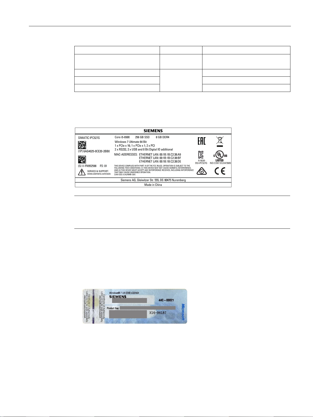
3.1.2
Identification data of the device
Identification date
Source
Value
Serial number
Product label
S VP ...
Order number of the device
Product label
6AG4025-0...
Production version
Product label
FS
3.1 Preparing for installation
6. If the contents of the packaging are incomplete, damaged or do not match your order,
inform the responsible delivery service immediately.
A damaged device can be under hazardous voltage and trigger a fire in the machine or
plant. A damaged device has unpredictable properties and states.
Death or serious injury could occur.
Make sure that the damaged device is not installed and put into operation. Label the
damaged device and keep it locked away. Send off the device for immediate repair.
If the device is subjected to low temperatures or extreme fluctuations in temperature
during transportation, for example in cold weather, moisture could build up on or inside
the device.
Moisture causes a short circuit in electrical circuits and damages the device.
In order to prevent damage to the device, proceed as follows:
• Store the device in a dry place.
• Bring the device to room temperature before starting it up.
• Do not expose the device to direct heat radiation from a heating device.
• If condensation develops, wait approximately 12 hours or until the device is
completely dry before switching it on.
7. Keep the enclosed documentation in a safe place. You need the documentation when
you commission the device for the first time or meet other problems in the later work.
8. Record the identification data of the device.
The device can be clearly identified with the help of this identification data in case of repairs
or theft.
Enter the identification data in the following table:
SIMATIC IPC527G
18 Operating Instructions, 03/2019, A5E45491226-AA
Installing and connecting the device
Identification date
Source
Value
Certificate of Authenticity (COA)
Ethernet address 1 (MAC)
Ethernet address 2 (MAC)
Product label
Note
Replacement device without storage media
When you
example HDD. Insert the storage media into the replacement device.
COA label
3.1 Preparing for installation
Microsoft Windows Product Key
Ethernet address 3 (MAC) (Optional)
Back of the device Only devices with preinstalled Windows
operating systems have COA labels
Product label
The following image shows the product label on the SIMATIC IPC527G as an example.
order a replacement device, remove all the storage media from your device, for
Microsoft Windows "Product Key" on the "Certificate Of Authenticity" (COA):
The COA label is only attached to the rear of the device containing a preinstalled and
activated Windows operating system.
● COA label of a device with Windows operating system
SIMATIC IPC527G
Operating Instructions, 03/2019, A5E45491226-AA
19
Installing and connecting the device
3.1.3
Permitted mounting positions
CAUTION
Points to note with expansion cards
Note
The device is approved
Ensure that the required minimum clearance of 100 mm to the area of the ventilation slots.
Desk mounting position
3.1 Preparing for installation
Expansion cards may impose restrictions on the installation location (fire-proof enclosure)
and permitted mounting positions (see General technical specifications (Page 62)). If the
device has been fitted with expansion cards, please observe the safety and installation
instructions for the expansion cards in the corresponding documentation.
If in doubt, install the device in an enclosure that is compliant with IEC/UL/EN/DIN-EN
60950-1, sections 4.6 and 4.7.3.
for indoor operation only.
The following mounting positions are permitted:
SIMATIC IPC527G
20 Operating Instructions, 03/2019, A5E45491226-AA
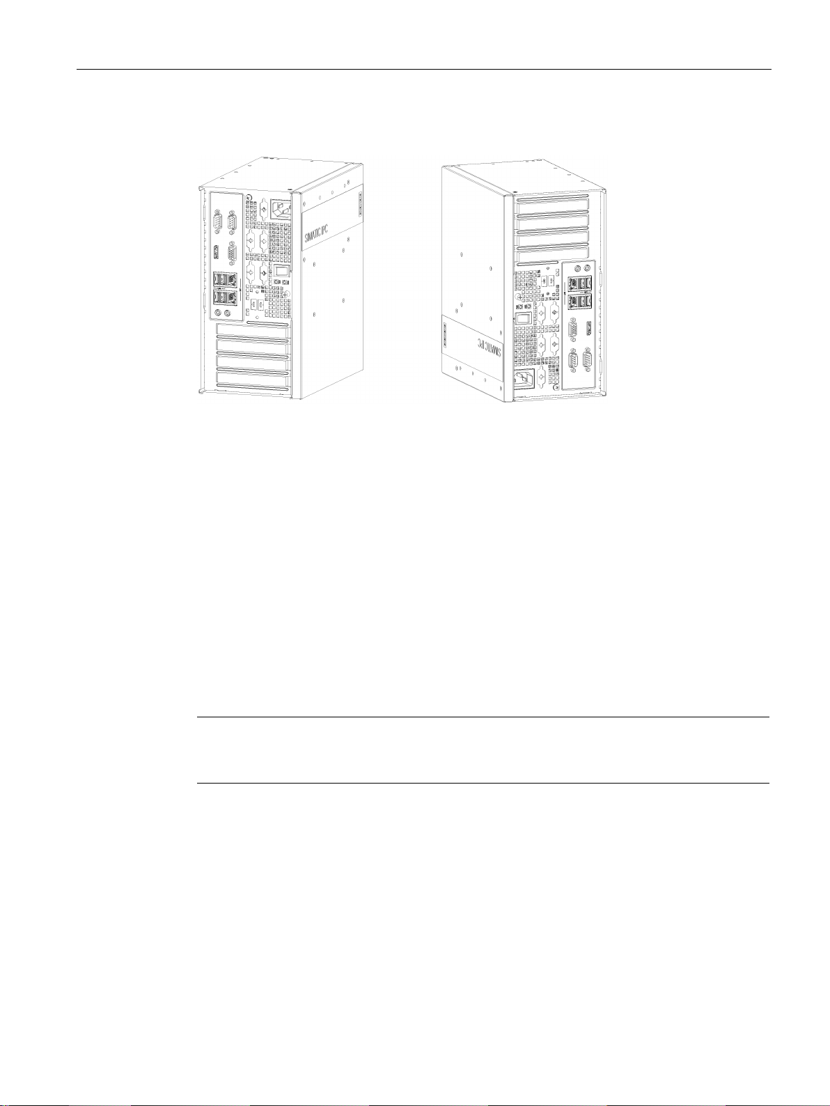
Installing and connecting the device
Vertical mounting position
3.2
Mounting the device
3.2.1
Mounting instructions
Note
If the equipment is used in a manner not specified by the manufacture, the protection
provided by the equipment might be impaired.
3.2 Mounting the device
For these two vertical mounting positions, you can use the following mounting types:
● Wall mounting
● Book mounting
● Tower mounting
Take into account the permitted temperature range for operation that depends on the
mounting position in accordance with the "Environmental conditions (Page 65)" section.
Note the following:
● The device is approved for indoor operation only.
● When the device is used in the area of Industrial Control Equipment in accordance with
UL61010-2-201, the device is classified as "Open equipment". Open equipment must be
installed within an enclosure which protects you from hazards, including mechanical
hazards, electrical shock and spread of fire.
● Install the device only in one of the described permitted mounting positions.
● For installation of control cabinet, observe the country-specific regulations.
● All the external circuit of the device must be SELV circuit.
SIMATIC IPC527G
Operating Instructions, 03/2019, A5E45491226-AA
21
Installing and connecting the device
Fasten securely
NOTICE
Insufficient load carrying capacity
NOTICE
Incorrect fixing elements
Material
Hole diameter
Fixing element
50 mm depth
Screws, 4-5 mm diameter, 40 mm long
min. 13 mm thick
long
WARNING
Personal injuries or material damage in the case of insufficient load-bearing capacity of wall
3.2 Mounting the device
● The device together with its AC power supply fulfils the requirements for fire protected
enclosures according to EN 60950-1. Therefore it can be installed without any additional
fire protective covering.
● Always maintain a minimum clearance of 100 mm to the area of the ventilation slots.
● This device is designed for use in a normal industrial environment. Without additional
protective measures (such as the provision of clean air), SIMATIC Box PCs may not be
operated in harsh environments that are subject to caustic vapors or gases.
If the mounting surface for wall and vertical mounting does not have sufficient load carrying
capability, the device may fall down and be damaged.
Ensure that the mounting surface on the wall can bear four times the total weight of the
device, including fixing elements.
If you use anchors and screws other than those specified below for wall and vertical
mounting, safe mounting is not guaranteed. The device can fall and may be damaged.
Use only the anchors and screws specified in the following table.
Use the following fasteners for the permitted mounting positions:
Concrete 6 mm diameter,
Plasterboard,
Metal,
min. 2 mm thick
14 mm diameter Tilting dowel: 4 mm diameter, at least 50 mm
5 mm diameter Metal screws: 4 mm diameter, at least 15 mm
Dowel, 6 mm diameter, 40 mm long
long
The device could fall if the wall to which it is mounted has insufficient load-bearing capacity.
This can result in personal injuries or material damage.
Ensure that the wall is capable of bearing four times the total weight of the device (including
the brackets and expansion modules). The total weight of the device is approximately 5 kg.
SIMATIC IPC527G
22 Operating Instructions, 03/2019, A5E45491226-AA
Installing and connecting the device
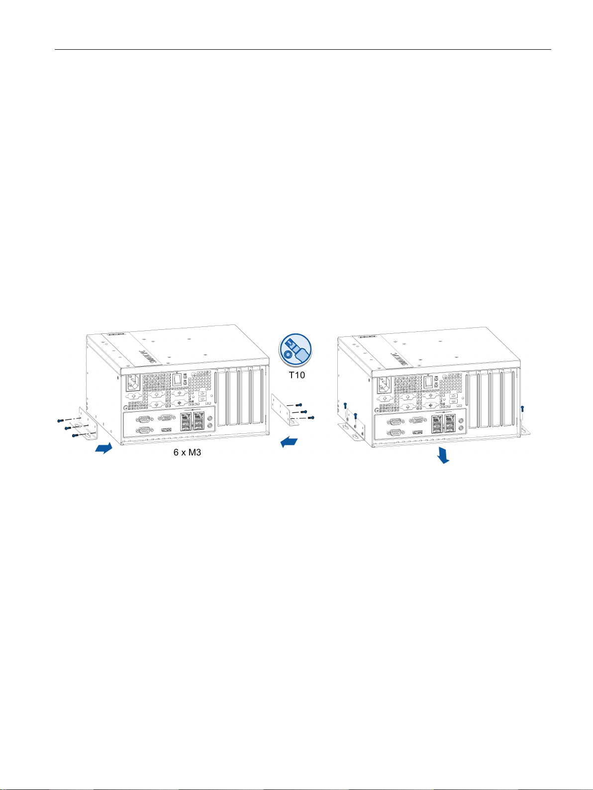
3.2.2
Desk mounting
Requirement
Procedure for mounting
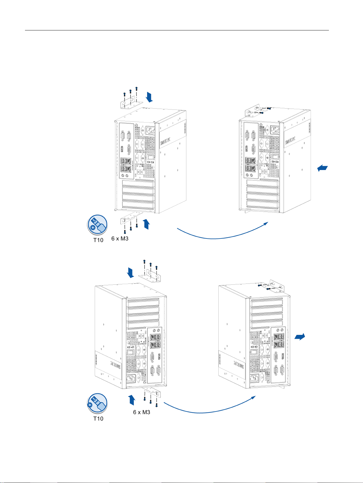
3.2.3
Wall mounting
Requirement
Procedure for mounting
3.2 Mounting the device
Desk mounting is suitable for horizontal mounting of the device.
● Two mounting brackets
● A T10 screwdriver
● 6 × M3 screws from deliver package
● Another four screws for mounting to a horizontal shelf
Secure each mounting bracket with 3 × M3 screws to the device. The maximum penetration
depth is 5 mm.
Use the marked threaded holes.
Wall mounting is one of the vertical mounting types.
● Two mounting brackets
● A T10 screwdriver
● 6 × M3 screws from deliver package
● Another four screws for mounting to the wall
Secure each mounting bracket with 3 × M3 screws to the device. The maximum penetration
depth is 5 mm.
SIMATIC IPC527G
Operating Instructions, 03/2019, A5E45491226-AA
23
Installing and connecting the device
3.2 Mounting the device
Use the marked threaded holes.
The wall mounting has two mounting positions:
● The interfaces are at the left.
● The interfaces are at the right.
SIMATIC IPC527G
24 Operating Instructions, 03/2019, A5E45491226-AA
Installing and connecting the device
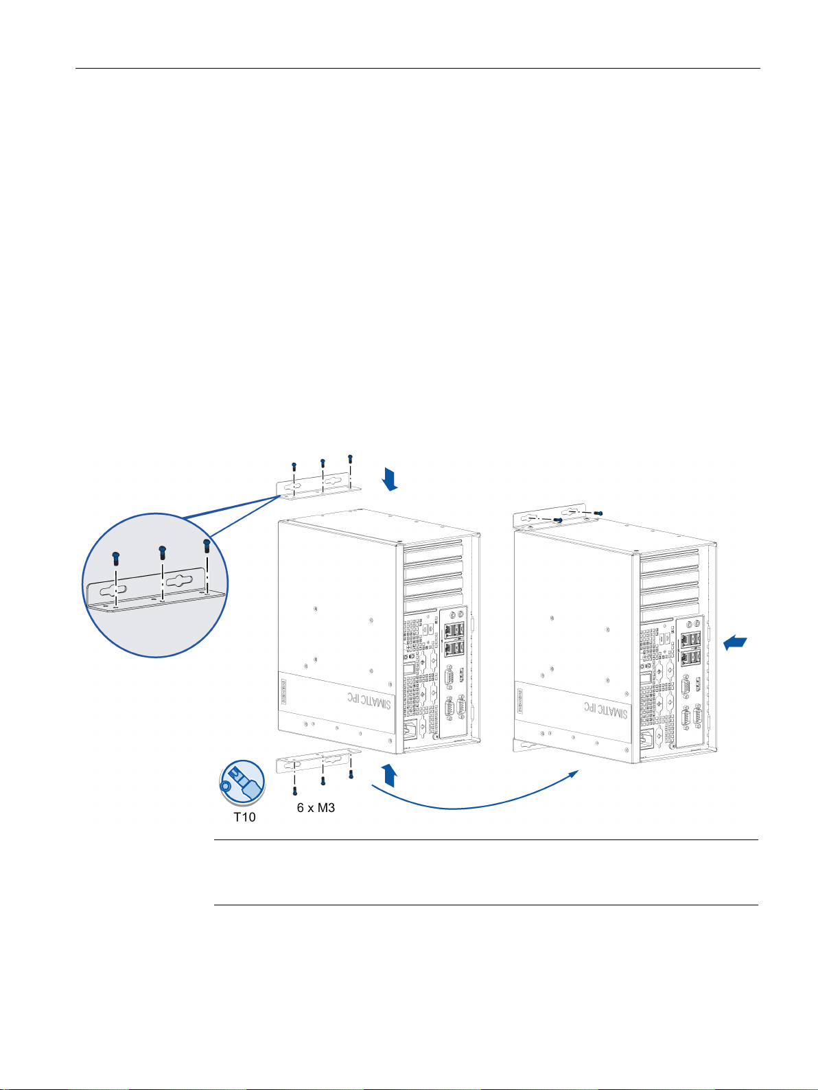
3.2.4
Book mounting
Requirement
Procedure for mounting
Note
In order to reserve some space for the ventilation, select the slot near the outside to
secure the screw.
3.2 Mounting the device
Book mounting is also suitable for vertical mounting of the device.
● Two mounting brackets
● A T10 screwdriver
● 6 × M3 screws from deliver package
● Another four screws for mounting to the wall
Secure each mounting bracket with 3 × M3 screws to the device. The maximum penetration
depth is 5 mm.
Use the marked threaded holes.
The book mounting has two mounting positions:
● The interfaces are at the front. Mount the device as the following image.
● The interfaces are also at the front. Rotate the device as shown in the above image
horizontally by 180 degrees to mount the device.
SIMATIC IPC527G
Operating Instructions, 03/2019, A5E45491226-AA
25
Installing and connecting the device
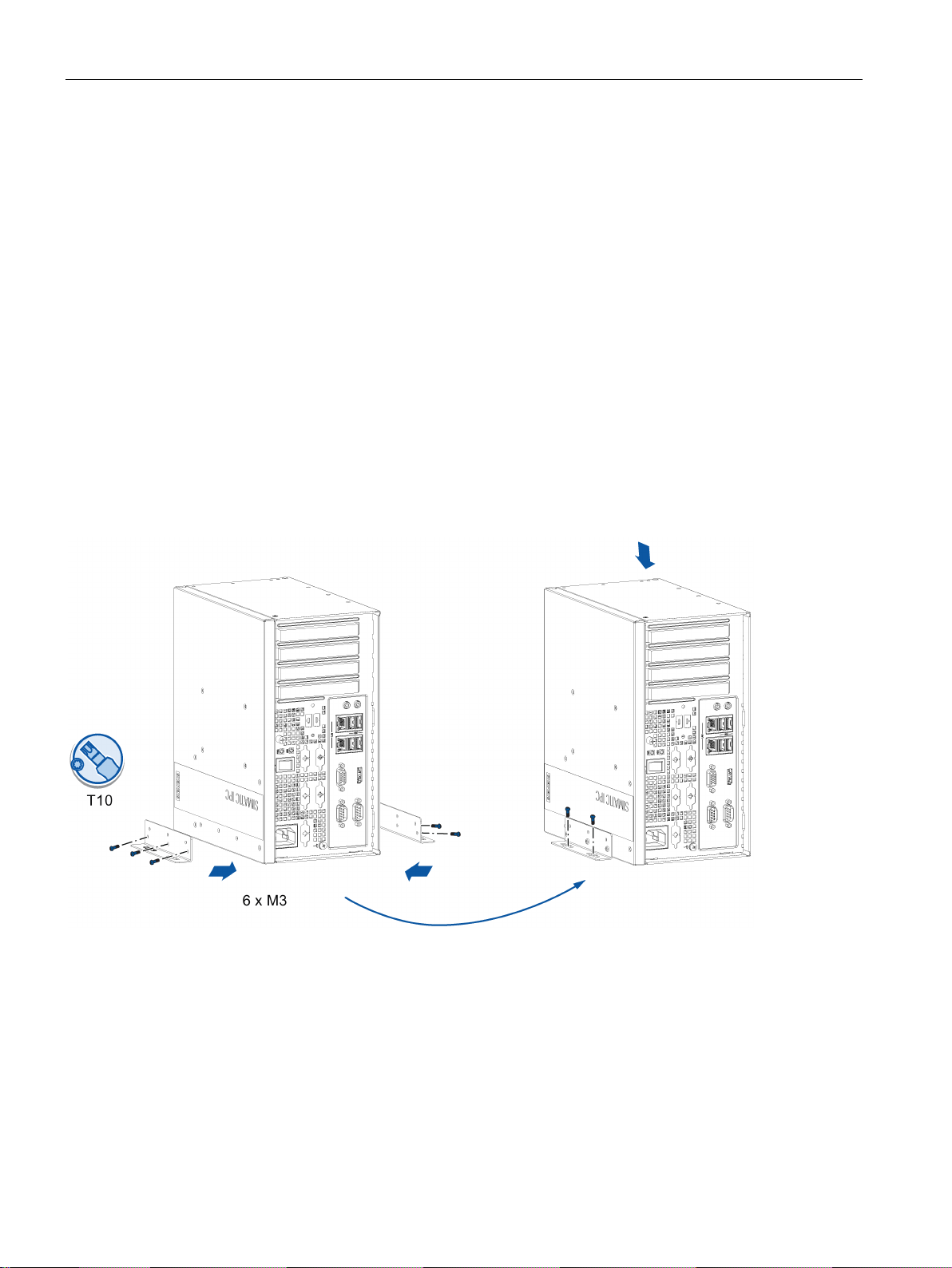
3.2.5
Tower mounting
Requirement
Procedure for mounting
3.2 Mounting the device
Tower mounting is one of the vertical mounting types and it is a space-saving installation of
the device.
● Two mounting brackets
● A T10 screwdriver
● 6 × M3 screws from deliver package
● Another four screws for mounting to a horizontal shelf
Secure each mounting bracket with 3 × M3 screws to the device. The maximum penetration
depth is 5 mm.
Use the marked threaded holes.
SIMATIC IPC527G
26 Operating Instructions, 03/2019, A5E45491226-AA
Installing and connecting the device
3.3
Connecting the device
3.3.1
Notes on connecting
WARNING
Risk of fire and electric shock
n/off switch does not isolate the device from the power supply. Risk of electric shock if
WARNING
Risk of lightning strikes
3.3.2
Connecting the function earth
3.3 Connecting the device
The o
the device is opened incorrectly or defective. There is also a risk of fire if the device or
connecting lines are damaged. Death or serious bodily injury can result.
You should therefore protect the device as follows:
• Always pull out the power plug when you are not using the device or if the device is
defective. The power plug must be freely accessible.
• Use a central power isolating switch for cabinet installation.
A lightning flash may enter the mains cables and data transmission cables and jump to a
person.
Death, serious injury and burns can be caused by lightning.
Take the following precautions:
• Disconnect the device from the power supply in good time when a thunderstorm is
approaching.
• Do not touch mains cables and data transmission cables during a thunderstorm.
• Keep a sufficient distance from electric cables, distributors, systems, etc.
A connected function earth discharges electrical charges from the metal enclosure.
The function earth also improves the discharge of interference generated by external power
cables, signal cables or cables for I/O modules to ground.
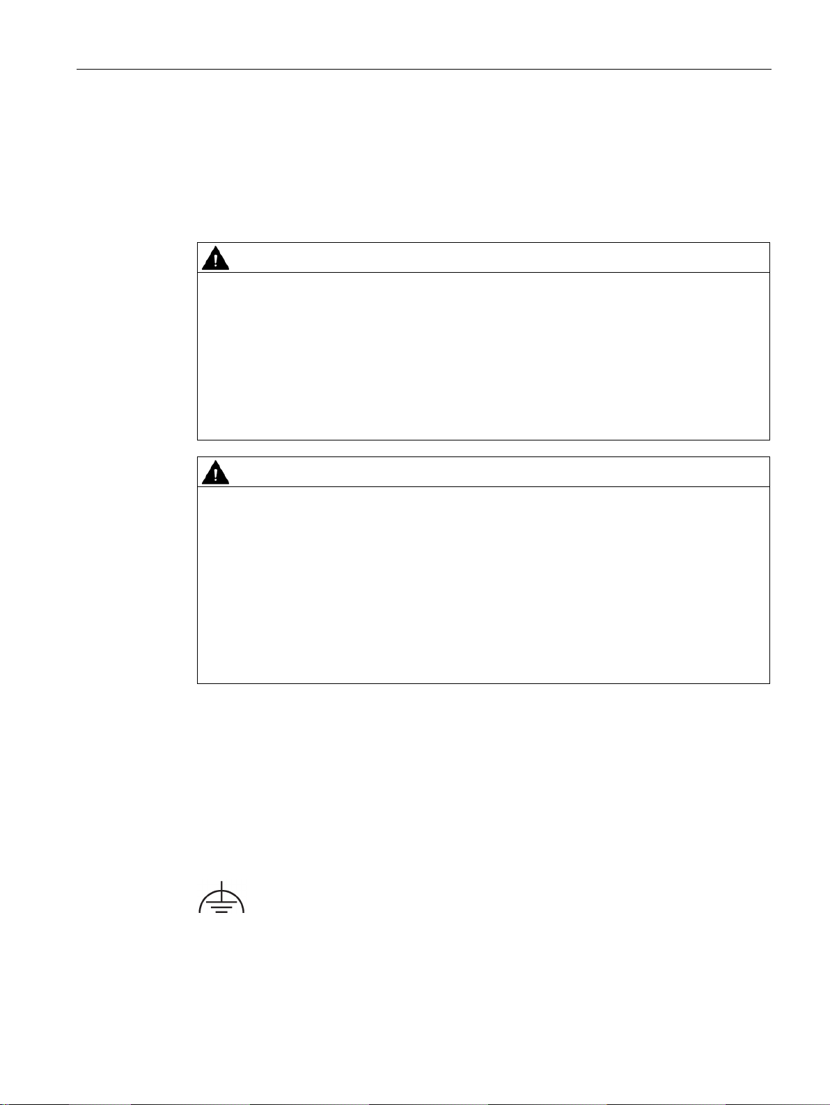
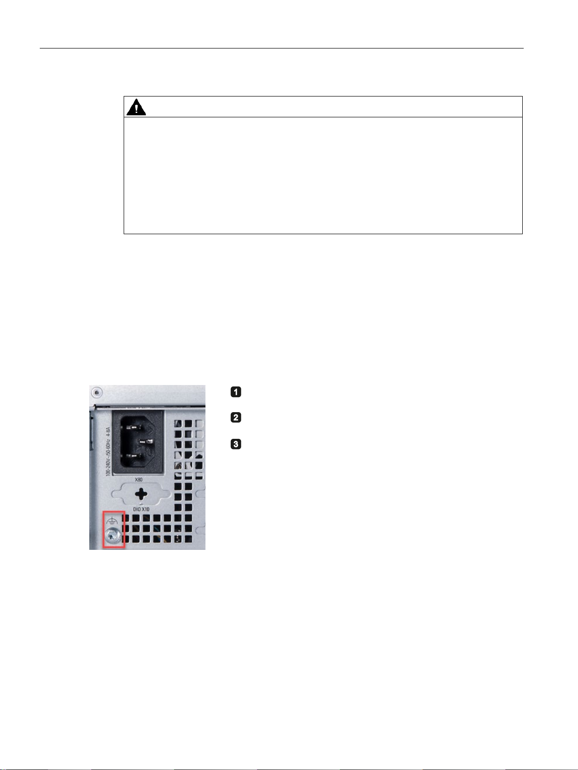
The connection for the function earth is labeled with the following symbol:
SIMATIC IPC527G
Operating Instructions, 03/2019, A5E45491226-AA
27
Installing and connecting the device
WARNING
Electric shock and risk of fire
Requirement
Procedure
Clamp the cable lug on the function earth.
Firmly attach the cable lug to the function earth connection on
the device using the M4 thread (see part label
Connect the function earth to the protective conductor
connection of the cabinet or the plant in which the device is
i
3.3 Connecting the device
High voltage may be present in a defective device, which can cause fire or an electric
shock if touched. Death and serious bodily injury can result.
• Connect the device to the function earth before you put it into operation.
• The function earth terminal on the device must be connected to the function earth of the
control cabinet or system in which the device is installed.
• Never operate the device without function earth.
• If a device is defective, remove it from operation without delay and label it accordingly.
● T20 screwdriver
● Cable lug for M4
● Function earth with minimum cross-section of 2.5 mm
2
copper cable
ed).
nstalled.
SIMATIC IPC527G
28 Operating Instructions, 03/2019, A5E45491226-AA

Installing and connecting the device
3.3.3
Connecting the power supply
Note before you connect the device
WARNING
Injuries to persons or damage to property when operated on an incorrect power supply
system
Country-specific information
230 V supply voltage of the USA and Canada
120 V supply voltage of the USA and Canada
240 V supply voltage
3.3 Connecting the device
If you connect the device to an unsuitable power supply, the device receives voltages and
currents too high or too low.
Injuries to persons, malfunctions or a damage to the device can result.
Note the following information regarding the power supply system:
• The permitted nominal voltage of the device must correspond to the local mains voltage.
• Do not operate the device in non-grounded or impedance-grounded networks (IT
networks).
• Operate the device only in grounded power networks (TN networks in accordance with
IEC 60364-1).
The power supply cable must conform to the safety regulations of the country in which the
devices are installed and bear the marks required in each case.
This device must be equipped with a safety-tested power cord which may only be connected
to a grounded shockproof power outlet. Use a flexible cable with the following features:
● Type SJT with three conductors
● The connector must be compliant with NEMA 5-15.
● Conductor cross-section ≤ 18 AWG
● Cable length ≤ 4.5 m
● Type SJT with three conductors
● The connector must be compliant with NEMA 5-15.
● Conductor cross-section ≤ 18 AWG
● Cable length ≤ 4.5 m
● Type SJT with three conductors
● Conductor cross-section ≤ 18 AWG
● Cable length ≤ 4.5 m
SIMATIC IPC527G
Operating Instructions, 03/2019, A5E45491226-AA
29
Installing and connecting the device
100 V supply voltage
220V supply voltage
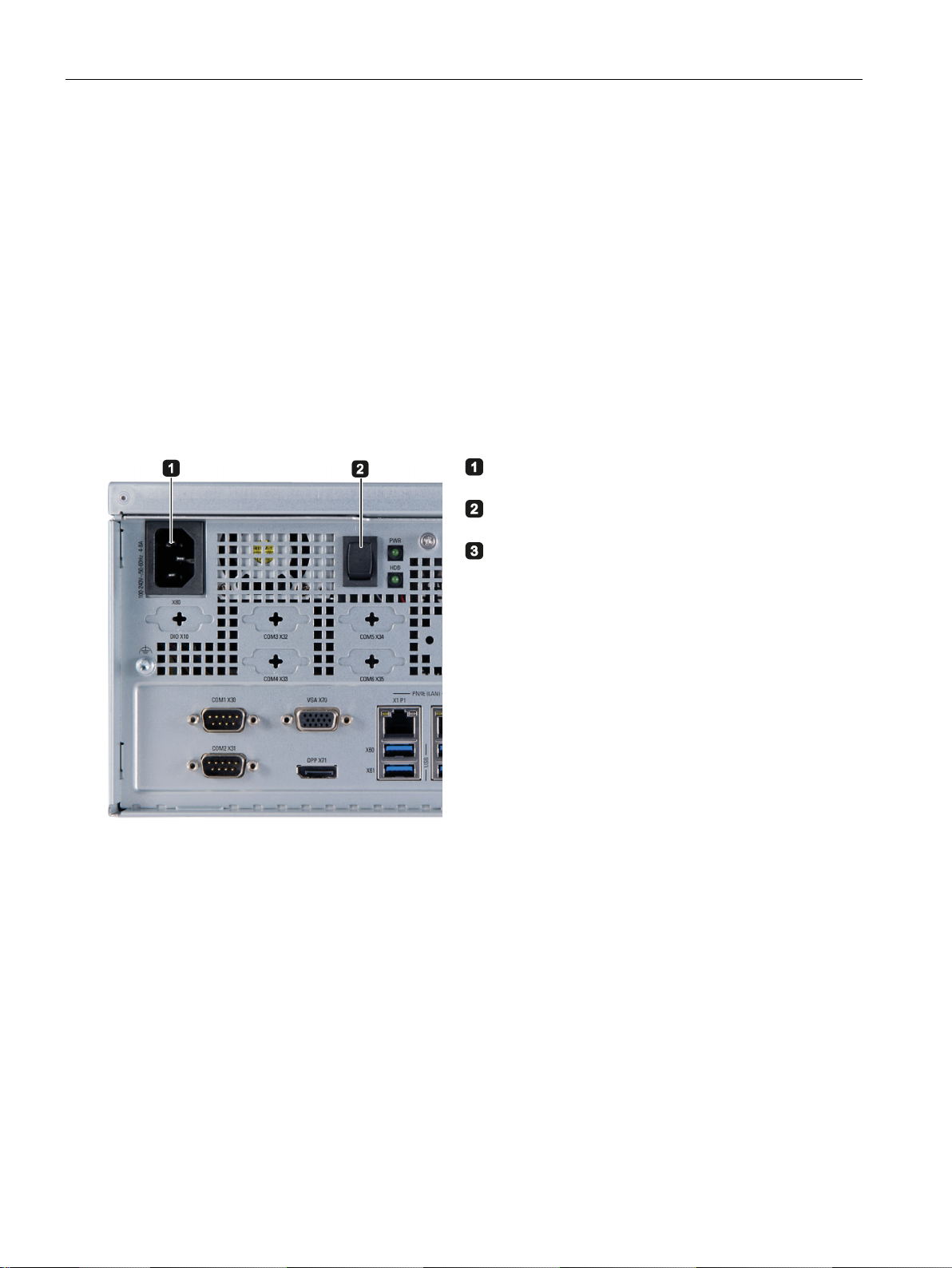
Connecting the power supply
Connect the power cable to socket
Insert the power cable in the electrical socket.
Press the power button ②
3.3 Connecting the device
● Type SJT with three conductors
● Conductor cross-section ≤ 18 AWG
● Cable length ≤ 4.5 m
● Type RVV with three conductors
● conductor cross-section ≤ 18 AWG
● Cable length ≤ 4.5 m
①.
.
SIMATIC IPC527G
30 Operating Instructions, 03/2019, A5E45491226-AA
 Loading...