

Page 1

SIMATIC
Industrial PC
SIMATIC IPC477E PRO
Operating Instructions
08/2017
A5E39912462
Preface
1
Overview
2
Safety guidelines
3
Mounting and connecting the
HMI device
4
Commissioning the device
5
Operating the device and
device functions
6
Expanding the device and
assigning the device
parameters
7
Maintaining and repairing the
device
8
Technical specifications
9
Technical support
A
Markings and symbols
B
List of abbreviations
C
-AA
Page 2

Siemens AG
Division Digital Factory
Postfach 48 48
90026 NÜRNBERG
GERMANY
A5E39912462-AA
Ⓟ
Copyright © Siemens AG 2017.
All rights reserved
Legal information
Warning notice system
DANGER
indicates that death or severe personal injury will result if proper precautions are not taken.
WARNING
may
CAUTION
indicates that minor personal injury can result if proper precautions are not taken.
NOTICE
indicates that property damage can result if proper precautions are not taken.
Qualified Personnel
personnel qualified
Proper use of Siemens products
WARNING
Siemens products may only be used for the applications described in the catalog and in the relevant technical
ambient conditions must be complied with. The information in the relevant documentation must be observed.
Trademarks
Disclaimer of Liability
This manual contains notices you have to observe in order to ensure your personal safety, as well as to prevent
damage to property. The notices referring to your personal safety are highlighted in the manual by a safety alert
symbol, notices referring only to property damage have no safety alert symbol. These notices shown below are
graded according to the degree of danger.
indicates that death or severe personal injury
If more than one degree of danger is present, the warning notice representing the highest degree of danger will
be used. A notice warning of injury to persons with a safety alert symbol may also include a warning relating to
property damage.
result if proper precautions are not taken.
The product/system described in this documentation may be operated only by
task in accordance with the relevant documentation, in particular its warning notices and safety instructions.
Qualified personnel are those who, based on their training and experience, are capable of identifying risks and
avoiding potential hazards when working with these products/systems.
Note the following:
documentation. If products and components from other manufacturers are used, these must be recommended
or approved by Siemens. Proper transport, storage, installation, assembly, commissioning, operation and
maintenance are required to ensure that the products operate safely and without any problems. The permissible
All names identified by ® are registered trademarks of Siemens AG. The remaining trademarks in this publication
may be trademarks whose use by third parties for their own purposes could violate the rights of the owner.
We have reviewed the contents of this publication to ensure consistency with the hardware and software
described. Since variance cannot be precluded entirely, we cannot guarantee full consistency. However, the
information in this publication is reviewed regularly and any necessary corrections are included in subsequent
editions.
for the specific
07/2017 Subject to change
Page 3

Table of contents
1 Preface ................................................................................................................................................... 7
2 Overview................................................................................................................................................. 9
3 Safety guidelines ................................................................................................................................... 21
4 Mounting and connecting the HMI device .............................................................................................. 27
5 Commissioning the device .................................................................................................................... 53
2.1 Product description ................................................................................................................... 9
2.2 Installation ............................................................................................................................... 11
2.2.1 Interfaces and operator controls for PRO device ................................................................... 13
2.3 Accessory kit ........................................................................................................................... 14
2.4 Accessories ............................................................................................................................. 14
2.5 System components ............................................................................................................... 15
2.5.1 Base adapter ........................................................................................................................... 15
2.5.2 Round tube adapter ................................................................................................................ 16
2.5.3 Adapter set for support arm and stand mounting of PRO device ........................................... 18
2.5.4 Extension Unit and operator controls ...................................................................................... 19
3.1 General safety instructions ..................................................................................................... 21
3.2 Notes on usage ....................................................................................................................... 24
4.1 Preparing for mounting ........................................................................................................... 27
4.1.1 Checking the delivery package ............................................................................................... 27
4.1.2 Device identification data ........................................................................................................ 29
4.2 Permitted mounting positions ................................................................................................. 31
4.3 Mounting the device ................................................................................................................ 33
4.3.1 Notes on mounting .................................................................................................................. 33
4.3.2 Prepared for support arm or stand without extension elements (flange on top) .................... 35
4.3.3 Prepared for support arm and extension elements (flange mount) ........................................ 38
4.4 Connecting the device ............................................................................................................ 42
4.4.1 Notes on connecting ............................................................................................................... 42
4.4.2 Power supply .......................................................................................................................... 44
4.4.2.1 Opening and closing the terminal compartment cover ........................................................... 44
4.4.2.2 connecting the PE conductor .................................................................................................. 47
4.4.2.3 Connecting the 24 VDC power supply .................................................................................... 48
4.4.3 Connecting peripheral equipment ........................................................................................... 50
4.4.4 Connecting the device to networks ......................................................................................... 51
4.4.5 Securing the cables ................................................................................................................ 52
5.1 Notes on commissioning and operation .................................................................................. 53
5.2 Initial commissioning ............................................................................................................... 55
5.3 Windows Action Center........................................................................................................... 57
SIMATIC IPC477E PRO
Operating Instructions, 08/2017, A5E39912462-AA
3
Page 4

Table of contents
6 Operating the device and device functions ............................................................................................ 59
7 Expanding the device and assigning the device parameters .................................................................. 75
8 Maintaining and repairing the device ..................................................................................................... 83
6.1 Operator input options ........................................................................................................... 59
6.2 Operating the device .............................................................................................................. 60
6.3 IPC Wizard functions ............................................................................................................. 62
6.4 Extended device functions ..................................................................................................... 63
6.4.1 Monitoring functions ............................................................................................................... 63
6.4.1.1 Overview of the monitoring functions ..................................................................................... 63
6.4.1.2 Temperature monitoring/display ............................................................................................ 64
6.4.1.3 Watchdog (WD)...................................................................................................................... 64
6.4.1.4 Battery monitoring .................................................................................................................. 65
6.4.1.5 Mass storage monitoring ........................................................................................................ 65
6.4.2 Enhanced Write Filter (EWF) ................................................................................................. 66
6.4.3 File Based Write Filter (FBWF) .............................................................................................. 69
6.4.4 Buffer memory NVRAM ......................................................................................................... 70
6.4.5 Active Management Technology (AMT) ................................................................................ 71
6.4.6 Trusted Platform Modul (TPM) ............................................................................................... 73
7.1 Opening and closing the backplane cover ............................................................................. 75
7.2 Installing and removing a memory module ............................................................................ 79
7.3 Installing and removing a CFast card .................................................................................... 81
7.4 Assigning CPU power consumption parameters ................................................................... 82
8.1 Maintenance ........................................................................................................................... 83
8.2 Repair information .................................................................................................................. 84
8.3 Cleaning the Device Front ..................................................................................................... 87
8.4 Installing and removing hardware .......................................................................................... 88
8.4.1 Replacing the backup battery ................................................................................................ 88
8.4.2 Replace SSD .......................................................................................................................... 89
8.5 Installing the software ............................................................................................................ 91
8.5.1 Reinstalling the operating system .......................................................................................... 91
8.5.1.1 General installation procedure ............................................................................................... 91
8.5.1.2 Restoring the factory state of the software ............................................................................ 92
8.5.1.3 Windows ................................................................................................................................. 93
8.5.1.4 Windows Embedded Standard .............................................................................................. 97
8.5.2 Partitioning the data storage medium .................................................................................... 98
8.5.2.1 Partitioning in Windows Embedded Standard 7 .................................................................... 98
8.5.2.2 Partitioning in Windows 7 Ultimate ........................................................................................ 99
8.5.2.3 Changing the partitions under Windows 7 and Windows 10 ................................................. 99
8.5.3 Installing drivers and software ............................................................................................. 100
8.5.4 Update installation ............................................................................................................... 101
8.5.4.1 Updating the operating system ............................................................................................ 101
8.5.4.2 Installing or updating application programs and drivers ...................................................... 101
8.5.5 Backing up data ................................................................................................................... 101
8.6 Recycling and disposal ........................................................................................................ 101
SIMATIC IPC477E PRO
4 Operating Instructions, 08/2017, A5E39912462-AA
Page 5

Table of contents
9 Technical specifications ...................................................................................................................... 103
9.1 Certificates and approvals .................................................................................................... 103
9.2 Directives and declarations ................................................................................................... 108
9.2.1 Electromagnetic compatibility ............................................................................................... 108
9.2.2 ESD guideline ....................................................................................................................... 108
9.3 Dimension drawings .............................................................................................................. 111
9.3.1 Dimension drawing of 15" device with capacitive multi-touch screen .................................. 111
9.3.2 Dimension drawing of 19" device with capacitive multi-touch screen .................................. 114
9.3.3 Dimension drawing of 22" device with capacitive multi-touch screen .................................. 117
9.4 Technical specifications ........................................................................................................ 120
9.4.1 General technical specifications ........................................................................................... 120
9.4.2 Environmental conditions ...................................................................................................... 125
9.4.3 Information on insulation tests, protection class and degree of protection........................... 126
9.4.4 Rated voltages ...................................................................................................................... 126
9.4.5 Power requirements of the components ............................................................................... 126
9.4.6 Integrated DC power supply ................................................................................................. 127
9.5 Hardware descriptions .......................................................................................................... 128
9.5.1 External interfaces ................................................................................................................ 128
9.5.1.1 COM1/COM2 ........................................................................................................................ 128
9.5.1.2 CFast..................................................................................................................................... 128
9.5.1.3 DisplayPort ............................................................................................................................ 129
9.5.1.4 Ethernet ................................................................................................................................ 130
9.5.1.5 USB 3.0 port ......................................................................................................................... 130
9.5.1.6 USB 2.0 ................................................................................................................................. 131
9.5.2 System resources ................................................................................................................. 131
9.5.3 Input/output areas ................................................................................................................. 133
9.5.3.1 Overview of the internal module registers ............................................................................ 133
9.5.3.2 Watchdog trigger register (read only, address 062h) ........................................................... 133
9.5.3.3 Watchdog enable register (read/write address 062h) ........................................................... 134
9.5.3.4 Battery status register (read only, if the RTC_BAT_SURVEY_EN address is set to "1";
404Dh) .................................................................................................................................. 135
9.5.3.5 NVRAM address register ...................................................................................................... 135
9.6 BIOS description ................................................................................................................... 136
9.6.1 Overview ............................................................................................................................... 136
9.6.2 Opening the BIOS selection menu ....................................................................................... 137
9.6.3 Structure of the BIOS Setup menu ....................................................................................... 139
9.6.4 Exit menu .............................................................................................................................. 141
9.6.5 BIOS update ......................................................................................................................... 142
9.6.6 Alarm, error and system messages ...................................................................................... 144
9.7 Active Management Technology (AMT)
...............................................................................
9.7.1 Introduction ........................................................................................................................... 145
9.7.2 Overview of AMT .................................................................................................................. 146
9.7.3 Enabling Intel® AMT / basic configuration ............................................................................ 146
9.7.4 Resetting the Intel® AMT to the default settings and disabling AMT ................................... 148
9.7.5 Determining the network address ......................................................................................... 148
9.7.6 Forcing user consent ............................................................................................................ 149
9.8 Functional scope in Windows ............................................................................................... 150
9.8.1 Windows Embedded Standard 7 .......................................................................................... 150
SIMATIC IPC477E PRO
Operating Instructions, 08/2017, A5E39912462-AA
145
5
Page 6

Table of contents
A Technical support................................................................................................................................. 153
B Markings and symbols ......................................................................................................................... 157
C List of abbreviations ............................................................................................................................. 161
Glossary .............................................................................................................................................. 167
Index ................................................................................................................................................... 175
A.1 Service and support ............................................................................................................. 153
A.2 Problem solving.................................................................................................................... 154
A.3 Notes on the use of third-party modules .............................................................................. 155
B.1 Overview .............................................................................................................................. 157
B.2 Safety ................................................................................................................................... 157
B.3 Operator controls ................................................................................................................. 157
B.4 Certificates, approvals and markings ................................................................................... 158
B.5 Interfaces ............................................................................................................................. 159
SIMATIC IPC477E PRO
6 Operating Instructions, 08/2017, A5E39912462-AA
Page 7

1
Purpose of the Operating Instructions
Basic knowledge required
Scope of the operating instructions
Scope of this documentation
These operating instructions contain all the information you need for commissioning and
operating the SIMATIC IPC477E PRO.
It is intended both for programming and testing personnel who commission the device and
connect it with other units (automation systems, programming devices), as well as for service
and maintenance personnel who install add-ons or carry out fault/error analyses.
A solid background in personal computers and Microsoft operating systems is required to
understand this manual. General knowledge in the field automation control engineering is
recommended.
These operating instructions apply to "SIMATIC IPC477E PRO" industrial PCs with article
numbers6AV7251-...-... .
The documentation for the IPC includes the following:
● Product information, e.g. "Important notes on your device"
● Quick Install Guide SIMATIC IPC477E PRO
● SIMATIC IPC477E PRO Operating Instructions
The documentation is supplied with the IPC in multiple languages as PDF on the USB stick
supplied in the documentation package.
SIMATIC IPC477E PRO
Operating Instructions, 08/2017, A5E39912462-AA
7
Page 8

Preface
Conventions
Note
A note is important information about the product, handling the product or a reference to
specific sections of the documentation that require special consideration.
History
Edition
Comments
08/2017
First edition
In these operating instructions, "device" is used as the standard term for "SIMATIC IPC477E
PRO".
In these operating instructions, the terms "Windows Embedded Standard 7 P" and "Windows
Embedded Standard 7 E" are also abbreviated with the term "Windows Embedded
Standard". "Windows 7" is used as an abbreviation for "Windows 7 Ultimate".
A touch device generally refers to a device with a capacitive multi-touch screen or a resistive
single touch screen. Touch screen is the general term for a resistive single touch screen or a
capacitive multi-touch screen.
The following editions of these operating instructions have already been published:
SIMATIC IPC477E PRO
8 Operating Instructions, 08/2017, A5E39912462-AA
Page 9
2
2.1
Product description
Features
SIMATIC IPC477E PRO provides high-level industrial functionality.
● Compact design
● Maintenance-free operation
● IP65 degree of protection
● Rugged
● Ex approval
● Used for shipping and offshore applications
● Expansion with system components
The range has been expanded by the PRO device with all-round IP65 degree of protection;
the device not only impresses with its ease of servicing, but also with its sophisticated design
and low mounting depth.
SIMATIC IPC477E PRO
Operating Instructions, 08/2017, A5E39912462-AA
9
Page 10

Overview
Device variants
PRO device with capacitive multi-touch screen
Operating systems
Operating system
Windows 10 IoT Enterprise (64-bit)
Windows 7 Ultimate
(32/64-bit)
Windows Embedded
Standard 7 P (32-bit)
Windows Embedded
Standard 7 E (32/64-bit)
x x x
x*
* WES7E is also supplied with IPC477E PRO devices. Multitouch is operated in single touch mode with WES7E.
2.1 Product description
The delivery note contains information on the precise scope of functions and product
package for your device.
The SIMATIC IPC477E PRO is available in the following device variants, which differ in
regard to the display size, operating method and optional expansions:
● Display:
– 15" display, resolution 1366 × 768 pixels
– 19" display, resolution: 1366 x 768 pixels
– 22" display, resolution: 1920 x 1080 pixels
● optionally prepared for:
– Support arm without extension components (flange at top)
– Support arm and extension components (round tube)
– Pedestal/extension components (flange at bottom)
● A base adapter and adapter sets that can be ordered separately support mounting
● Fully dust-proof and splash-proof with IP65 degree of protection and Enclosure Type
The following table shows the operating systems that are available:
systems from various manufacturers.
– Base adapter for support arm and pedestal included in the product package.
– Cover plate for device version for support arm and extension components included in
the product package.
4X / 12 (indoor use only)
SIMATIC IPC477E PRO
10 Operating Instructions, 08/2017, A5E39912462-AA
Page 11
Overview
2.2
Installation
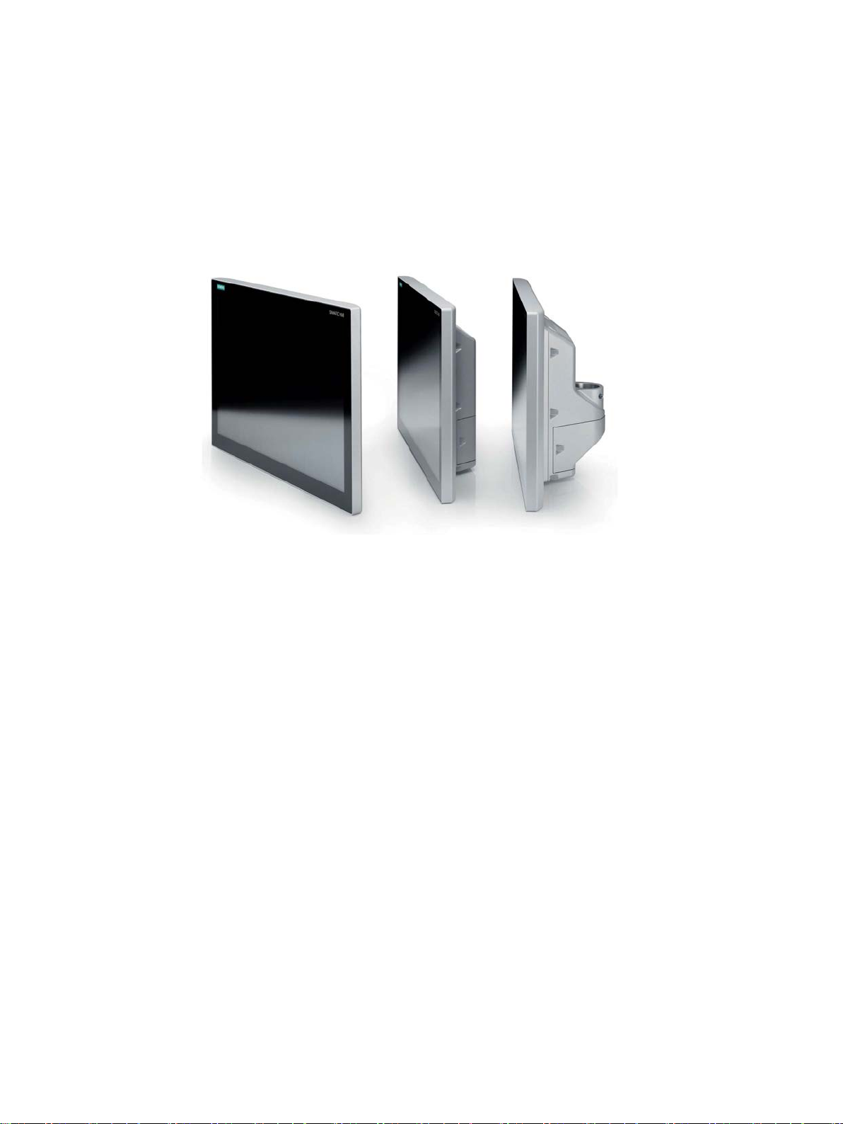
Front view and side view
①
Display with multi-touch screen
②
Enclosure
③
Backplane cover
④
Terminal compartment cover
Bottom view
①
Mechanical interface for mounting/base adapter
2.2 Installation
SIMATIC IPC477E PRO
Operating Instructions, 08/2017, A5E39912462-AA
11
Page 12
Overview
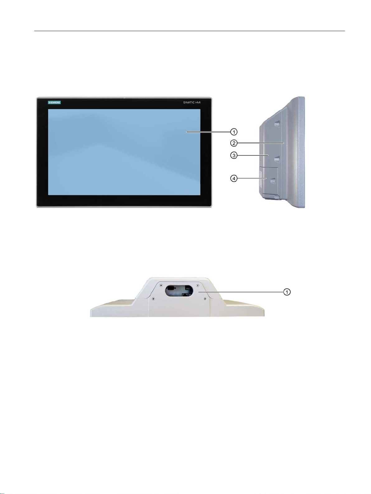
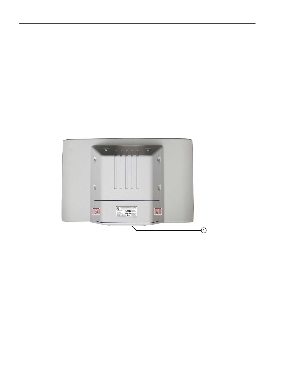
Rear view - device version "prepared for pedestal/extension components" and "prepared for support
arm without extension components".
①
Backplane cover
②
Terminal compartment cover
③
Mechanical interface for mounting/base adapter
Rear view - device version "prepared for support arm and extension components"
①
Terminal compartment cover
2.2 Installation
SIMATIC IPC477E PRO
12 Operating Instructions, 08/2017, A5E39912462-AA
Page 13
Overview
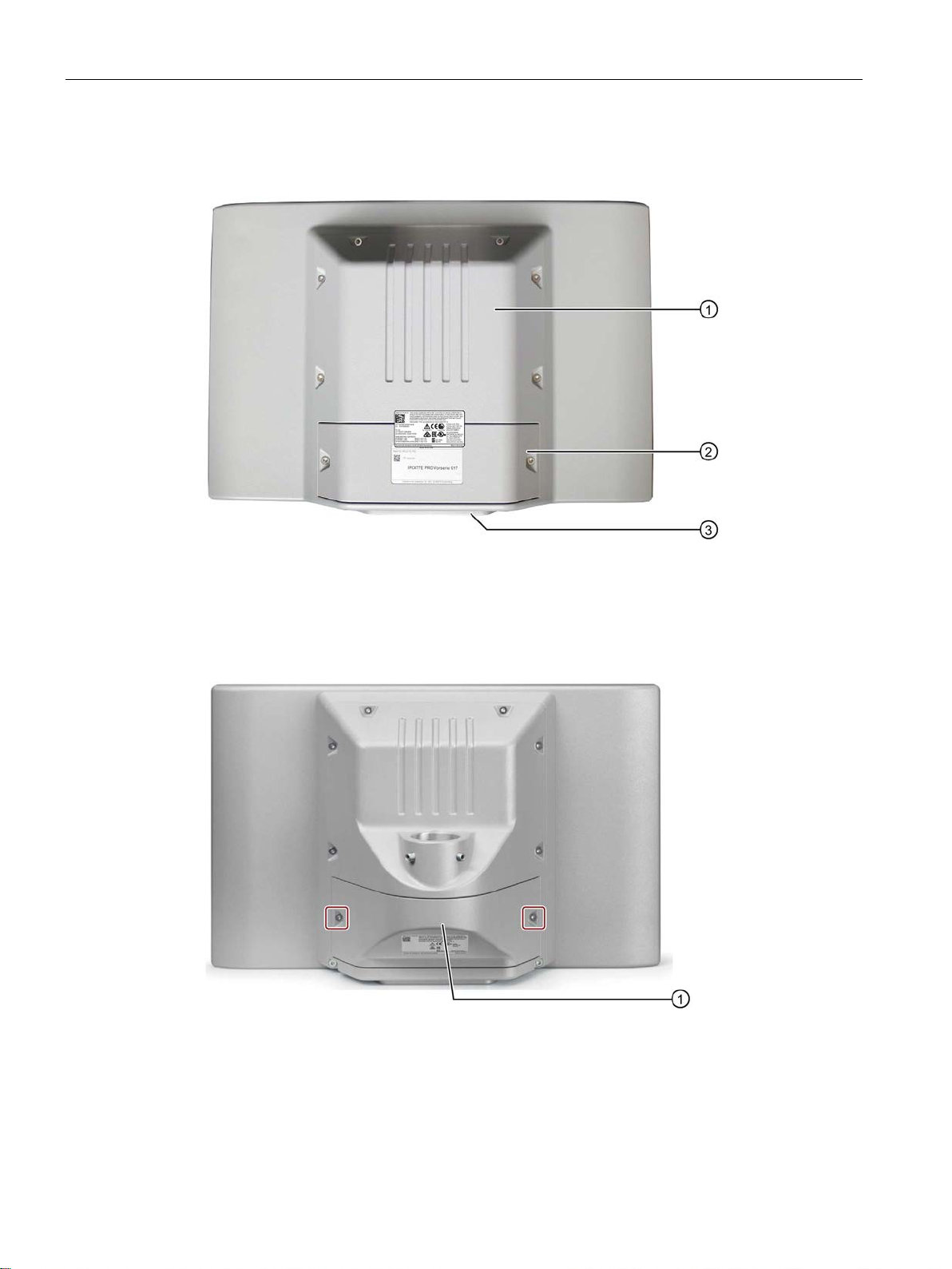
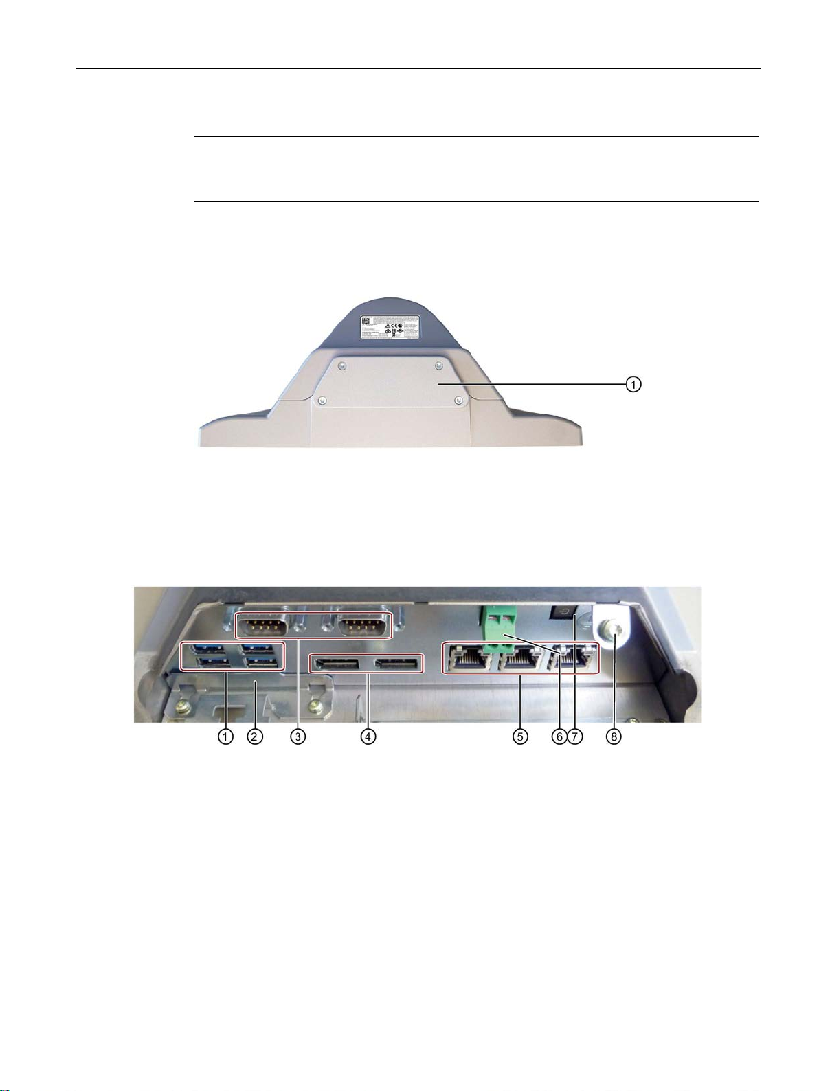
Note
The device version "prepared for support arm and extension components" is intended for
devices with an extension (see
Bottom - device version "prepared for support arm and extension elements"
①
Cover plate
2.2.1
Interfaces and operator controls for PRO device
①
4 x USB port
USB 3.0 high speed/high current
②
Slot for CFast card
Behind the strain relief
③
COM1/2 port (optional)
Serial port, 9-pin D-sub connector
④
Display port
⑤ 3 × Ethernet port
RJ45 Ethernet port, 10/100/1000 Mbps
⑥
24 V DC power supply
⑦
On/off switch
⑧
Protective conductor connection
2.2 Installation
System components (Page 15)).
Connection terminal
The assignment of the interfaces is shown inside the terminal compartment cover.
Connection terminal inserted in delivered condition
SIMATIC IPC477E PRO
Operating Instructions, 08/2017, A5E39912462-AA
13
Page 14

Overview
2.3
Accessory kit
PRO device
2.4
Accessories
SIMATIC IPC CFast cards
2.3 Accessory kit
● The base adapter including four M4x12 screws is included in the scope of delivery for
devices "prepared for support arm without extension elements (flange on top)" and
devices "prepared for stand/extension elements (flange on bottom)".
● The device version "prepared for support arm and extension components" includes a
cover plate with four M4x12 screws in the product package.
● Additional documents may be supplied with the accessory kit.
Accessories are available for your device. These are not included in the product package.
You can find Information on available accessories on the Internet at:
Industry Mall (https://mall.industry.siemens.com)
Expansion components and accessories (http://www.automation.siemens.com/mcms/pc-
based-automation/en/industrial-pc/expansion_components_accessories)
System components for devices with all-round IP65 protection
https://mall.industry.siemens.com/mall/de/de/Catalog/Products/10268745?tree=CatalogTree)
(
● 2 GB optional or
● 4 GB optional or
● 8 GB optional or
● 16 GB optional or
● 30 GB optional
SIMATIC IPC477E PRO
14 Operating Instructions, 08/2017, A5E39912462-AA
Page 15
Overview
2.5
System components
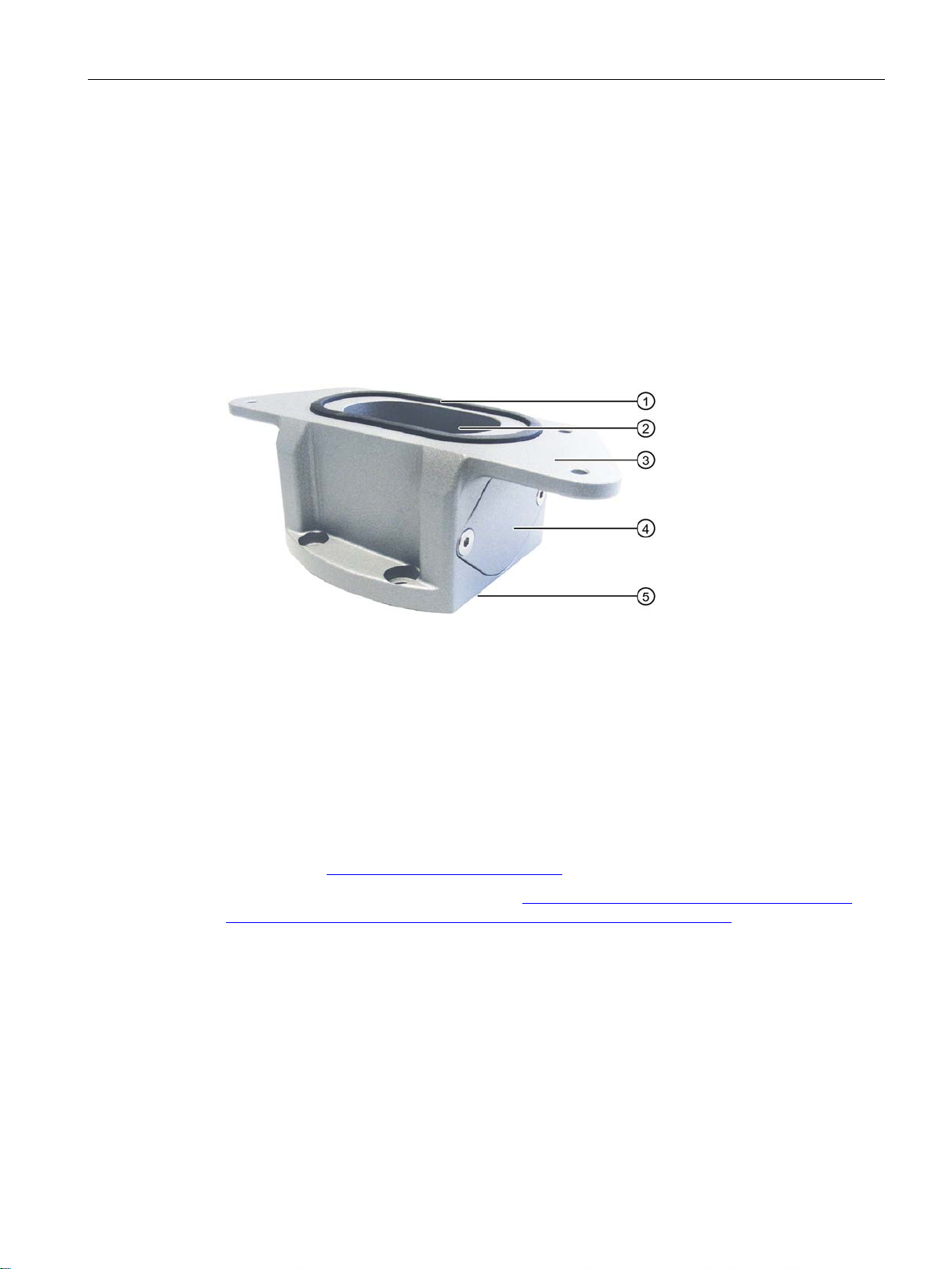
2.5.1
Base adapter
①
Seal
②
Cable channel
③
Mechanical interface to the PRO device
④
Cover
⑤
Mechanical interface to support arm or stand
See also
2.5 System components
PRO devices of the type "suitable for support arm" or "suitable for stand" can be mounted on
a support arm or stand using the base adapter. Depending on the support arm system used,
an adapter plate may have to be installed in addition (see Accessories (Page 14)).
A base adapter is included with the corresponding PRO devices. The base adapter can also
be ordered separately.
Article number for the base adapter as accessory: 6AV7674-1KA00-0AA0.
Prepared for support arm or stand without extension elements (flange on top) (Page 35)
Industry Mall (https://mall.industry.siemens.com)
Expansion components and accessories (http://www.automation.siemens.com/mcms/pc-
based-automation/en/industrial-pc/expansion_components_accessories)
SIMATIC IPC477E PRO
Operating Instructions, 08/2017, A5E39912462-AA
15
Page 16
Overview
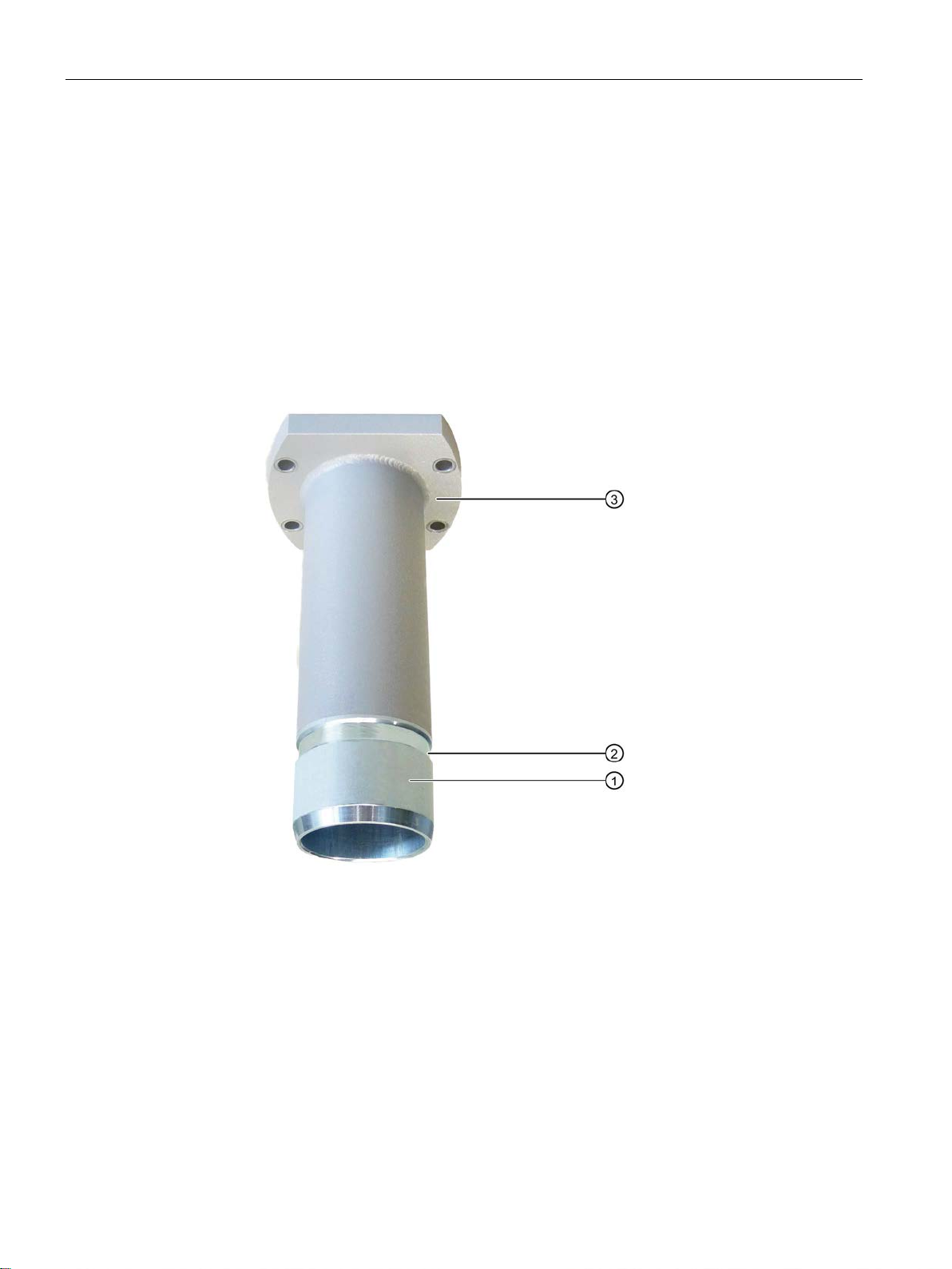
2.5.2
Round tube adapter
Flange mount for device version "prepared for support arm and extension components"
①
Flange mount
②
Ring groove for fastening on PRO device with setscrews
③
Mechanical interface to support arm
2.5 System components
An optional flange mount that is not included in the product package is available for the
device version "prepared for support arm and extension components".
The flange mount converts the flange mount connection into a mechanically compatible
interface to the base adapter. The flange of the flange mount has the same drilling pattern as
the base adapter. This means you can use all couplings of the support arm or pedestal
systems with mechanical interface for the base adapter.
Article number of the flange mount: 6AV7674-1KF00-0AA0
SIMATIC IPC477E PRO
16 Operating Instructions, 08/2017, A5E39912462-AA
Page 17

Overview
Additional information
See also
2.5 System components
You can find information on mounting the PRO device at Prepared for support arm and
extension elements (flange mount) (Page 38).
You can find Information on available accessories on the Internet at:
● Industry Mall (https://mall.industry.siemens.com)
● System components for devices with all-round IP65 protection
https://mall.industry.siemens.com/mall/de/de/Catalog/Products/10268745?tree=CatalogTree)
(
Prepared for support arm or stand without extension elements (flange on top) (Page 35)
SIMATIC IPC477E PRO
Operating Instructions, 08/2017, A5E39912462-AA
17
Page 18

Overview
2.5.3
Adapter set for support arm and stand mounting of PRO device
Adapter set
Suitable for support arm systems
Article number
Information provided without guarantee.
2.5 System components
The PRO device can be mounted on systems from third-party vendors (see section
"Mounting the device (Page 33)"). For this you will need the Siemens base adapter (see
Base adapter (Page 15)) and a proprietary adapter set.
Siemens also offers its own adapter for VESA-compatible third-party systems:
SIEMENS:
• Adapter set VESA75
• Adapter set VESA100
RITTAL:
Adapter for
Siemens PRO-Panel
• Intermediate plate
• Screws
ROLEC:
Adapter for
Siemens PRO-Panel
• Intermediate plate
• Screws
BERNSTEIN:
Coupling for Siemens
SIMATIC PRO
• No intermediate plate re-
quired
• Coupling with integrated
adaptation for PRO device
• VESA75-compatible systems
• VESA100-compatible systems
• CP40 steel
• CP60/120 for
Support arm connection
120 × 65 mm
• profiPlus-50
• taraPLUS for ∅ 65 mm hole
circle
• CS-3000 • 1015300187 RAL 9006
• 6AV7674-0KE00-0AA0
• 6AV7674-0KD00-0AA0
• 6206.500
• 142.024.000
white aluminum
• 1015300043 RAL 7016
anthracite gray
SIMATIC IPC477E PRO
18 Operating Instructions, 08/2017, A5E39912462-AA
Page 19

Overview
2.5.4
Extension Unit and operator controls
Extension components - Extension Unit
Note
Only operator controls with Siemens approval may be installed in the Extension Unit.
You can find information on "System components for PRO device Extension Units" on the
Internet (
2.5 System components
The Extension Unit is used to install additional operator controls under a SIMATIC PRO
device of the type "Suitable for extension components" with 16:9 display.
The example in the figure below shows the Extension Unit 22" with eight operator controls
including emergency stop button.
The Extension Units have individual configuration possibilities and are supplied without
operator controls. The available slots are suitable for installation of operator controls.
The extension units are available in 4 different sizes:
● 12"
● 15"
● 19"
● 22"
For greater flexibility, three different connection options can be selected per size for the PLC
connection of the operator controls:
● Hardwired
● PROFINET
● PROFIsafe
In addition, different operator controls such as emergency stop, selector switch, illuminated
pushbutton, keyswitch, indicator light or RFID reader are available.
https://support.industry.siemens.com/cs/de/de/view/109742323/en).
SIMATIC IPC477E PRO
Operating Instructions, 08/2017, A5E39912462-AA
19
Page 20

Overview
Additional information
2.5 System components
Information on system components for devices with all-round IP65 protection is available on
the Internet
(https://mall.industry.siemens.com/mall/de/de/Catalog/Products/10268745?tree=CatalogTree).
SIMATIC IPC477E PRO
20 Operating Instructions, 08/2017, A5E39912462-AA
Page 21

3
3.1
General safety instructions
WARNING
Life-threatening voltages are present with an open control cabinet
System expansions
NOTICE
Damage through system expansions
When you install the device in a control cabinet, some areas or components in the open
control cabinet may be carrying life-threatening voltages.
If you touch these areas or components, you may be killed by electric shock.
Switch off the power supply to the cabinet before opening it.
Device and system expansions may be faulty and can affect the entire machine or plant.
The installation of expansions can damage the device, machine or plant. Device and
system expansions may violate safety rules and regulations regarding radio interference
suppression. If you install or exchange system expansions and damage your device, the
warranty becomes void.
Note the following for system expansions:
• Only install system expansion devices designed for this device. Contact your technical
• Read the information on electromagnetic compatibility (Page 108).
support team or where you purchased your PC to find out which system expansion
devices may safely be installed.
SIMATIC IPC477E PRO
Operating Instructions, 08/2017, A5E39912462-AA
21
Page 22
Safety guidelines
Battery and rechargeable battery
WARNING
Risk of explosion and release of harmful substances
Strong high-frequency radiation
NOTICE
Observe immunity to RF radiation
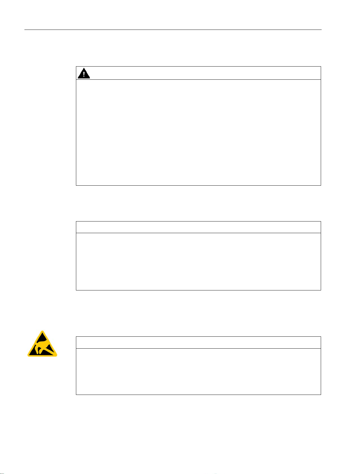
ESD Guideline
NOTICE
Electrostatic sensitive devices (ESD)
3.1 General safety instructions
Improper handling of lithium batteries can result in an explosion of the batteries.
Explosion of the batteries and the released pollutants can cause severe physical injury.
Worn batteries jeopardize the function of the device.
Note the following when handling lithium batteries:
• Replace spent batteries promptly. You can find information on installing and removing
the backup battery in the Operating Instructions.
• Replace the lithium battery only with an identical battery or types recommended by the
manufacturer.
• Do not throw lithium batteries into fire, do not solder on the cell body, do not recharge,
do not open, do not short-circuit, do not reverse polarity, do not heat above 100°C and
protect from direct sunlight, moisture and condensation.
The device has an increased immunity to RF radiation according to the specifications on
electromagnetic compatibility in the technical specifications.
Radiation exposure in excess of the specified immunity limits can impair device functions,
result in malfunctions and therefore injuries or damages.
Read the information on immunity to RF radiation in the technical specifications.
Electrostatic sensitive devices can be labeled with an appropriate symbol.
When you touch electrostatic sensitive components, you can destroy them through voltages
that are far below the human perception threshold.
If you work with components that can be destroyed by electrostatic discharge, observe the
ESD Guideline (Page 108).
SIMATIC IPC477E PRO
22 Operating Instructions, 08/2017, A5E39912462-AA
Page 23

Safety guidelines
Industrial Security
Disclaimer for third-party software updates
Notes on protecting administrator accounts
3.1 General safety instructions
Siemens provides products and solutions with industrial security functions that support the
secure operation of plants, systems, machines and networks.
In order to protect plants, systems, machines and networks against cyber threats, it is
necessary to implement – and continuously maintain – a holistic, state-of-the-art industrial
security concept. Siemens’ products and solutions only form one element of such a concept.
Customer is responsible to prevent unauthorized access to its plants, systems, machines
and networks. Systems, machines and components should only be connected to the
enterprise network or the internet if and to the extent necessary and with appropriate security
measures (e.g. use of firewalls and network segmentation) in place.
Additionally, Siemens’ guidance on appropriate security measures should be taken into
account. For more information about industrial security, please visit.
Siemens’ products and solutions undergo continuous development to make them more
secure. Siemens strongly recommends to apply product updates as soon as available and to
always use the latest product versions. Use of product versions that are no longer supported,
and failure to apply latest updates may increase customer’s exposure to cyber threats.
To stay informed about product updates, subscribe to the Siemens Industrial Security RSS
Feed under.
This product includes third-party software. Siemens AG only provides a warranty for
updates/patches of the third-party software, if these have been distributed as part of a
Siemens software update service contract or officially released by Siemens AG. Otherwise,
updates/patches are undertaken at your own risk. You can find more information about our
Software Update Service offer on the Internet at Software Update Service.
A user with administrator privileges has extensive access and manipulation options in the
system.
Therefore, ensure there are adequate safeguards for protecting the administrator accounts
to prevent unauthorized changes. To do this, use secure passwords and a standard user
account for normal operation. Other measures, such as the use of security policies, should
be applied as needed.
SIMATIC IPC477E PRO
Operating Instructions, 08/2017, A5E39912462-AA
23
Page 24

Safety guidelines
3.2
Notes on usage
WARNING
Risks associated with the unprotected machine or plant
Environment
NOTICE
Ambient conditions and chemical resistance
3.2 Notes on usage
According to the results of a risk analysis, certain hazard potentials associated with the
unprotected machine exist. These hazards could lead to personal injury.
Avoid such hazards by taking the following precautions in accordance with the risk analysis:
• Installation of additional safety equipment on the machine or plant. In particular, the
programming, parameter assignment and wiring of the inserted I/O modules must be
executed in accordance with the safety performance identified by the necessary risk
analysis (SIL, PL or Cat.).
• Use as intended must be validated for the device by means of a function test on the
plant. These tests help you to identify programming, parameter assignment and wiring
errors.
• Documentation of the test results that you can enter in the relevant safety verification
documents, if necessary.
Unsuitable environmental conditions have a negative impact on device operation. Chemical
substances such as cleaners or fuels may alter the color, shape and structure of the device
surface, for example, the front panel.
The device may be damaged. possibly resulting in malfunctions.
For this reason, please observe the following precautions:
• Always operate the device in closed rooms. All warranties shall be void in the case of
noncompliance.
• Operate the device only in accordance with the ambient conditions specified in the
technical specifications.
• Protect the device against heat.
• Do not expose the device to direct sunlight or to other strong sources of light.
• Without additional safety measures, such as a supply of clean air, the device may not be
used in locations with harsh operating conditions caused by acidic vapors or gases.
• Always use suitable cleaning agents. Read the information about Chemical resistance of
the HMI devices and industrial PCs
(http://support.automation.siemens.com/WW/view/en/39718396) on the Internet.
SIMATIC IPC477E PRO
24 Operating Instructions, 08/2017, A5E39912462-AA
Page 25

Safety guidelines
Note
Use in an industrial environment without additional protective measures
The device has been designed for use in a normal industrial
IEC
TFT displays
NOTICE
Burn-in effect and backlighting
Defective pixels in the display
3.2 Notes on usage
environment in accordance with
60721-3-3 (pollutant class 3C2 for chemical influences, 3S2 for dust without sand).
A permanent picture with bright screen objects leads to a burn-in effect. The longer the
same screen contents are displayed, the longer it will take for the burn-in effect to
disappear. Screensavers (for example, "starfield simulation") for the backlit active black
mode reduce the burn-in effect. The brightness of the backlighting deteriorates over the
course of the screen's life cycle.
The service life of the screen and backlighting is extended by the following measures:
• Switch on the screensaver. The backlight brightness is reduced while the screensaver is
active.
• You should also reduce the backlighting.
• Observe the backlighting operating time.
At present, the manufacturing process of modern displays does not guarantee that all pixels
of the display will be perfect. A small number of defective pixels in the display is therefore
unavoidable. This does not present a functional problem as long as the defective pixels are
not bunched in one location.
Additional information is available in the section "General technical specifications
(Page 120)".
SIMATIC IPC477E PRO
Operating Instructions, 08/2017, A5E39912462-AA
25
Page 26

Safety guidelines
3.2 Notes on usage
SIMATIC IPC477E PRO
26 Operating Instructions, 08/2017, A5E39912462-AA
Page 27

4
4.1
Preparing for mounting
4.1.1
Checking the delivery package
Procedure
Note
Damage to the device during transport and storage
If a device is transported or stored without packaging, shocks, vibrations, pressure and
moisture may impact the unprotected unit. Damaged packaging indicates that ambient
conditions
This may cause the device, machine or plant to malfunction.
•
•
1. When accepting a delivery, please check the packaging for visible transport damage.
2. If any transport damage is present at the time of delivery, lodge a complaint at the
shipping company in charge. Have the shipper confirm the transport damage
immediately.
3. Unpack the device at its installation location.
4. Keep the original packaging in case you have to transport the unit again.
have already had a massive impact on the device and it may be damaged.
Keep the original packaging.
Pack the device in the original packaging for transportation and storage.
5. Check the contents of the packaging and any accessories you may have ordered for
completeness and damage.
SIMATIC IPC477E PRO
Operating Instructions, 08/2017, A5E39912462-AA
27
Page 28

Mounting and connecting the HMI device
WARNING
Electric shock and fire hazard due to damaged device
NOTICE
Damage from condensation
4.1 Preparing for mounting
6. Please inform the delivery service immediately if the package contents are incomplete or
damaged or do not correspond with your order. Fax the enclosed form "SIMATIC IPC/PG
Quality Control Report".
A damaged device can be under hazardous voltage and trigger a fire in the machine or
plant. A damaged device has unpredictable properties and states.
Death or serious injury could occur.
Make sure that the damaged device is not inadvertently installed and put into operation.
Label the damaged device and keep it locked away. Send off the device for immediate
repair.
If the device is subjected to low temperatures or extreme fluctuations in temperature
during transportation, as is the case in cold weather, for example, moisture can build up
on or inside the device (condensation).
Moisture causes a short circuit in electrical circuits and damages the device.
In order to prevent damage to the device, proceed as follows:
• Store the device in a dry place.
• Bring the device to room temperature before starting it up.
• Do not expose the device to direct heat radiation from a heating device.
• If condensation develops, wait approximately 12 hours or until the device is
completely dry before switching it on.
7. Please keep the enclosed documentation in a safe place. It belongs to the device. You
need the documentation when you commission the device for the first time.
8. Write down the identification data of the device.
SIMATIC IPC477E PRO
28 Operating Instructions, 08/2017, A5E39912462-AA
Page 29
Mounting and connecting the HMI device
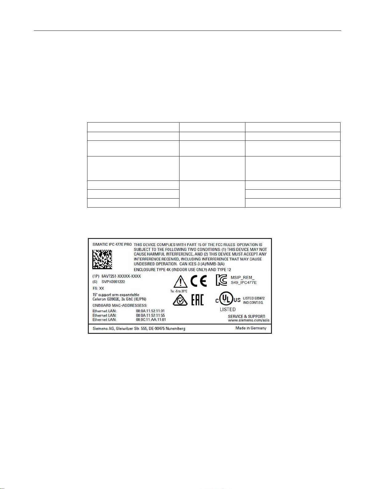
4.1.2
Device identification data
Unpacking the device
Identification date
Source
Value
Serial number
Rating plate
S VP ...
(SIMATIC IPC477E PRO)
Windows operating system.
Ethernet address 1
Ethernet address 2
Ethernet address 3
Example of a SIMATIC IPC477E PRO rating plate
4.1 Preparing for mounting
The device can be clearly identified with the help of this identification data in case of repairs
or theft.
Enter the identification data in the table below:
Article number of the device Rating plate 6AV7251...
Microsoft Windows Product Key
Certificate of Authenticity
In the device (remove
cover of terminal compartment)
BIOS setup, "Advanced"
menu
The COA label is for available with
pre-installed
SIMATIC IPC477E PRO
Operating Instructions, 08/2017, A5E39912462-AA
29
Page 30
Mounting and connecting the HMI device
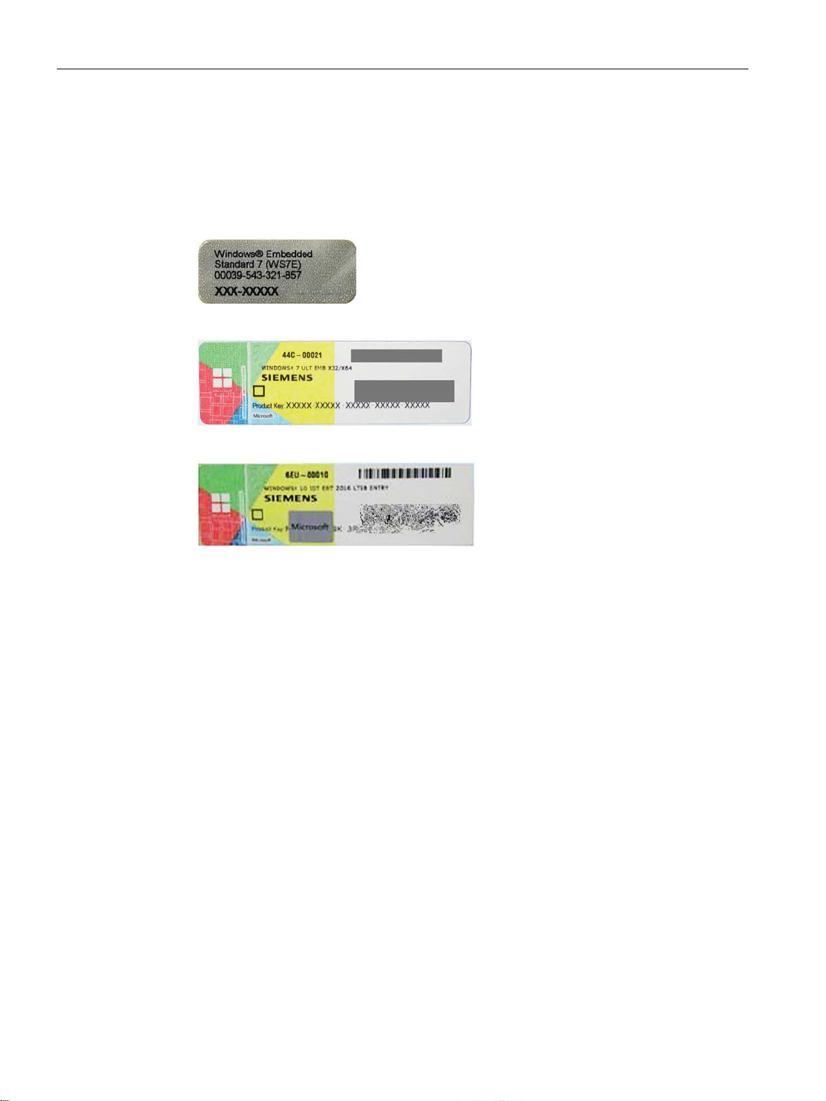
COA label
4.1 Preparing for mounting
Microsoft Windows "Product Key" from the "Certificate of Authenticity" (COA):
The COA label is present only when Windows Embedded Standard 7 or Windows 7 is
installed.
● COA label of a device with the Windows Embedded Standard 7 operating system
● COA label of a device with Windows 7 operating system
● COA label of a device with Windows 10 operating system
SIMATIC IPC477E PRO
30 Operating Instructions, 08/2017, A5E39912462-AA
Page 31

Mounting and connecting the HMI device
4.2
Permitted mounting positions
Mounting position
Device version "prepared for pedestal/extension components (flange at bottom)"
position
①
Inclined
≤ 45°
②
Vertical
0°
Device version "prepared for support arm without extension components (flange at top)"
Mounting position
①
Inclined
≤ 45°
②
Vertical
0°
4.2 Permitted mounting positions
The mounting positions described below are permitted for the PRO devices.
● Standard mounting position: Vertical installation in horizontal format
● Inclined installation in horizontal format with a vertical inclination of maximum ±45°
Upright mounting in vertical format is prohibited for the PRO device
Mounting
Deviation from the vertical
SIMATIC IPC477E PRO
Operating Instructions, 08/2017, A5E39912462-AA
31
Page 32

Mounting and connecting the HMI device
Device version "prepared for support arm and extension components (round tube)"
Mounting position
①
Inclined
≤ 45°
②
Vertical
0°
4.2 Permitted mounting positions
SIMATIC IPC477E PRO
32 Operating Instructions, 08/2017, A5E39912462-AA
Page 33

Mounting and connecting the HMI device
4.3
Mounting the device
4.3.1
Notes on mounting
WARNING
The device must be mounted securely.
NOTICE
Degree of protection for overall device
4.3 Mounting the device
Inadequately dimensioned fasteners may cause the device to fall down. Serious physical
injury may result.
Make sure that fasteners are adequately dimensioned during installation. Make sure to
consider the weight of the device and the forces acting on the device when dimensioning.
This applies in particular to dynamic load of the device. All fasteners including mounting
surfaces, support arm systems, and fastening elements such as screws must be able to
carry at least four times the weight of the device.
Observe any further statutory specifications applying at the location of use of the device
and further applicable regulations with regard to fastening the device.
Pay attention to the torque specifications in the following sections.
If you are using a support arm system or a pedestal system that does not have IP65 degree
of protection or Enclosure Type 4X / 12 (indoor use only), IP65 degree of protection and
Enclosure Type 4X / 12 (indoor use only) are voided for the entire device. Spray and water
jets as well as penetrating substances can then damage the device.
Only use a support arm system or pedestal system that has IP65 degree of protection and
Enclosure Type 4X / 12 (indoor use only).
SIMATIC IPC477E PRO
Operating Instructions, 08/2017, A5E39912462-AA
33
Page 34

Mounting and connecting the HMI device
Note
Liability disclaimer
The device is mounted to a pedestal or a support arm via the mechanical interface with
screws. Siemens AG assumes no liability for the consequences of incorrect installation.
Warranty at risk
If you do not install the HMI device in accordance with the specifications in these operating
instructions, the warranty for the device is voided.
•
•
IP65 degree of protection and Enclosure Type 4X / 12 (indoor use only) at risk
If there are no seals on the mechanical interfaces or if they are damaged, IP65 degree of
protection and Enclo
proper seating of the seals.
NOTICE
Damaging the seal when opening
4.3 Mounting the device
Always install the device according to these operating instructions.
If the seal on the backplane cover is damaged, it can be repaired. For a repair scenario,
following the instructions in the section "Repair information (Page 84)".
sure Type 4X / 12 (indoor use only) is at risk. Check the condition and
If the device has not been opened for a long time, the backplane cover or terminal
compartment cover may stick to the seal of the enclosure. Opening the device with
excessive force or with tools will destroy the seal. Spray and water jets as well as
penetrating substances can then damage the device.
Open the terminal compartment cover gently, without too much pressure.
SIMATIC IPC477E PRO
34 Operating Instructions, 08/2017, A5E39912462-AA
Page 35

Mounting and connecting the HMI device
4.3.2
Prepared for support arm or stand without extension elements (flange on top)
Note
Mounting without base adapter
If you install the device without a base adapter, you must adjust the mechanical interface
between the support arm or pedestal and
appropriate seal on the mechanical interface of the device.
Requirements
4.3 Mounting the device
the unit accordingly, including placement of an
● All packaging components and protective films have been removed.
● Siemens base adapter with screws (supplied with the device version "prepared for
support arm without extension components (flange at top)" and "prepared for
pedestal/extension components (flange at bottom)").
● One of the following support arms or pedestal systems:
– Support arm or pedestal with mechanical VESA interface and the corresponding
Siemens adapter set
– Support arm or pedestal with mechanical interface for the Siemens base adapter
The type of mechanical interface differs depending on the type of support arm or
pedestal.
See section "System components (Page 15)"
● The following cables are fed through the pedestal or the support arm to which the device
is mounted:
– Protective conductor
– Power supply cable
– Data cables, e.g. USB
For even large connectors to fit, run their cables through the pedestal or support arm
first.
SIMATIC IPC477E PRO
Operating Instructions, 08/2017, A5E39912462-AA
35
Page 36

Mounting and connecting the HMI device
Procedure
NOTICE
Observe the torques
too much
too low
4.3 Mounting the device
This section describes the mounting of the device to a support arm system. Installation on a
pedestal is carried out in the same way.
For devices of the type "suitable for support arm", the base adapter is screwed to the device
from the top; for devices of the type "suitable for pedestal", it is screwed from below.
A device for a support arm system cannot be used on a pedestal, and vice versa.
If you apply
torque to tighten the screws of the backplane cover and the terminal
compartment cover or the screws for fastening the device to a support arm or pedestal, the
threads of the enclosure, intermediate plate or support arm may be damaged.
If you tighten the screws with a torque that is
, the device is not sealed.
1. If an adapter plate for the Siemens base adapter is included in your support arm system,
attach the adapter plate to the support arm with 4 M6x12 screws. Pay attention to the
torque that is specified for the support arm.
2. Attach the base adapter with 4 M6x12 screws to the mechanical interface of the support
arm from below. Pay attention to the torque that is specified for the support arm.
SIMATIC IPC477E PRO
36 Operating Instructions, 08/2017, A5E39912462-AA
Page 37

Mounting and connecting the HMI device
①
Support arm head
②
Intermediate plate
③
Base adapter
④
Countersunk head screws for device
⑤
Screws for terminal compartment cover
Recommendation
4.3 Mounting the device
3. Remove the screws ⑤ of the terminal compartment cover.
4. Open the terminal compartment cover ⑤ and set it aside safely.
5. Insert all connection cables through the opening of the PRO device.
Make sure that the connecting cables are not damaged.
through the pedestal or support arm first.
6. Attach the device with 4 M4x12 countersunk head screws to the base adapter
the top, torque 2.5 Nm.
Make sure that the connecting cables are not pinched.
7. Connect all cables according to the description in the section Connecting the device
(Page 42).
8. Fasten the cover plate
Check that the seal is sitting correctly.
: Route large connectors (e.g. RS232 connectors) and their cables
③ from
⑤ to the device with the 2 screws, torque 1.5 Nm.
SIMATIC IPC477E PRO
Operating Instructions, 08/2017, A5E39912462-AA
37
Page 38

Mounting and connecting the HMI device
4.3.3
Prepared for support arm and extension elements (flange mount)
Requirements
4.3 Mounting the device
● One of the following support arm systems:
– Support arm with round tube end with an exterior diameter of 48.3 mm +/-0.5 mm,
appropriate for the opening of the PRO device
When selecting the flange mount, ensure its inner diameter is large enough to allow all
required cables and their connectors to pass through.
– Support arm with mechanical interface, appropriate for the flange of the flange mount,
and Siemens flange mount (not included in product package)
– Support arm with mechanical VESA interface, the corresponding Siemens adapter set
and the Siemens flange mount (not included in product package)
See System components (Page 15))
● All packaging components and protective films have been removed.
● The lower cover of the PRO device is included in the accessory kit.
● The following cables are fed through the support arm to which the device is mounted:
– Protective conductor
– Power supply cable
– Data cables, e.g. USB
For even large connectors to fit, run their cables through the pedestal or support arm
first, for example, RS232.
SIMATIC IPC477E PRO
38 Operating Instructions, 08/2017, A5E39912462-AA
Page 39
Mounting and connecting the HMI device
Procedure
NOTICE
Observe the torques
too much
too low
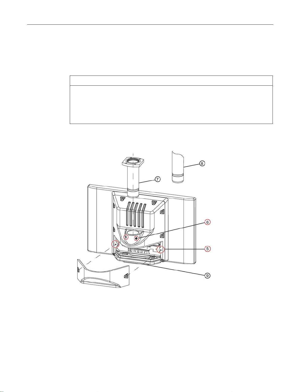
⑤
Screws for terminal compartment cover
⑥
Setscrews
⑦
Flange mount (not included in the product package; see System components (Page 15))
⑧
Third-party round tube (∅ 48 mm)
⑨
Cover plate (Included in the product package; see Accessory kit (Page 14))
4.3 Mounting the device
The following description shows an example of how to attach the PRO device to a support
arm system using the optionally available Siemens flange mount
round tube
⑧ that fits the opening of the PRO device is performed in a similar fashion.
⑦. Mounting to a 48.3 mm
If you apply
torque to tighten the screws of the backplane cover and the terminal
compartment cover or the screws for fastening the device to a support arm or pedestal, the
threads of the enclosure, intermediate plate or support arm may be damaged.
If you tighten the screws with a torque that is
, the device is not sealed.
1. Remove the screws ⑤ of the terminal compartment cover.
2. Open the terminal compartment cover and set it aside safely.
SIMATIC IPC477E PRO
Operating Instructions, 08/2017, A5E39912462-AA
39
Page 40

Mounting and connecting the HMI device
NOTICE
48.3 mm round tube ⑧
4.3 Mounting the device
3. Grease the flange mount ⑦ or 48.3 mm round tube ⑧ with grease suitable for NBR
seals, and insert the flange mount
opening of the PRO device.
Make sure that the sealing ring (O-ring) is not damaged. Fasten the flange mount with the
2 setscrews
Observe the appropriate torque:
⑥ M8x10 from the accessory kit.
⑦ or 48.3 mm round tube ⑧ into the corresponding
– Siemens flange mount
– 48.3 mm round tube of steel
– 48.3 mm round tube of aluminum
For the device to not loosen and drop in case of vibrations, the round tube must offer a
groove into which the setscrews can be fitted.
Otherwise the device can become loose due to vibrations and drop.
4. If an adapter plate ⑨ for the Siemens flange mount is included with your support arm,
attach the adapter plate to the support arm with 4 M6x12 screws. Pay attention to the
torque that is specified for the support arm.
⑦: 8 Nm
⑧: 8 Nm
⑧: 5 Nm
SIMATIC IPC477E PRO
40 Operating Instructions, 08/2017, A5E39912462-AA
5. Insert all connection cables through the opening of the flange mount or 48.3 mm round
tube into the connection compartment of the PRO device. Make sure that the connection
cables are not damaged.
6. Attach the device with 4 M4x12 screws to the support arm from the below.
The screws are not included in the product package of the PRO device.
Pay attention to the torque that is specified for the support arm.
Make sure that all connecting cables are fed through the flange mount into the interior of
the device without damage.
7. Connect all cables according to the description in the section Connecting the device
(Page 42).
Page 41

Mounting and connecting the HMI device
4.3 Mounting the device
8. Fasten the cover plate ⑤ to the device with the 2 screws, torque 1.5 Nm. Check that the
seal is sitting correctly.
9. Fasten the cover plate
⑨ from the PRO device product package with 4 M4x12 screws,
torque 1.5 Nm.
Alternatively, you can extend the PRO device by adding an Extension Unit at the bottom.
Read the associated documentation.
SIMATIC IPC477E PRO
Operating Instructions, 08/2017, A5E39912462-AA
41
Page 42

Mounting and connecting the HMI device
4.4
Connecting the device
4.4.1
Notes on connecting
WARNING
Risk of fire and electric shock
WARNING
Risk of lightning strikes
NOTICE
Fault caused by I/O devices
4.4 Connecting the device
The on/off switch does not isolate the device from the power supply. Risk of electric shock if
the device is opened incorrectly or defective. There is also a risk of fire if the device or
connecting lines are damaged.
You should therefore protect the device as follows:
• Always pull out the power plug when you are not using the device or if the device is
defective. The power plug must be freely accessible.
• Connect the device to a protective conductor as instructed, see section "Connecting the
protective conductor".
• Use a central isolating switch in the case of cabinet installation.
A lightning flash may enter the mains cables and data transmission cables and jump to a
person.
Death, serious injury and burns can be caused by lightning.
Take the following precautions:
• Disconnect the device from the power supply in good time when a thunderstorm is
approaching.
• Do not touch mains cables and data transmission cables during a thunderstorm.
• Keep a sufficient distance from electric cables, distributors, systems, etc.
The connection of I/O devices can cause faults in the device.
The result may be personal injury and damage to the machine or plant.
Note the following when connecting I/O devices:
• Read the documentation of the I/O devices. Follow all instructions in the documentation.
• Only connect I/O devices which are approved for industrial applications in accordance
with EN 61000-6-2 and IEC 61000-6-2.
• I/O devices that are not hotplug-capable may only be connected after the device has
been disconnected from the power supply.
SIMATIC IPC477E PRO
42 Operating Instructions, 08/2017, A5E39912462-AA
Page 43

Mounting and connecting the HMI device
NOTICE
Damage through regenerative feedback
4.4 Connecting the device
Regenerative feedback of voltage to ground by a connected or installed component can
damage the device.
Connected or built-in I/Os, for example, a USB drive, are not permitted to supply any
voltage to the device. Regenerative feedback is generally not permitted.
SIMATIC IPC477E PRO
Operating Instructions, 08/2017, A5E39912462-AA
43
Page 44
Mounting and connecting the HMI device
4.4.2
Power supply
4.4.2.1
Opening and closing the terminal compartment cover
Requirements
Opening the terminal compartment cover
4.4 Connecting the device
● The device is disconnected from the power supply.
● Torx TX20 screwdriver
Opening the terminal compartment cover for pedestal and support arm device versions
without extension components.
SIMATIC IPC477E PRO
44 Operating Instructions, 08/2017, A5E39912462-AA
Page 45

Mounting and connecting the HMI device
NOTICE
Damaging the seal when opening
4.4 Connecting the device
Opening the terminal compartment for device version prepared for support arm and
extension components (round tube).
1. Loosen the indicated M4x16 screws.
If the device has not been opened for a long time, the backplane cover and terminal
compartment cover may stick to the enclosure due to the seal. Opening the device with
excessive force or with tools will destroy the seal. Spray and water jets as well as
penetrating substances can then damage the device.
Open the terminal compartment cover gently, without too much pressure.
2. Carefully lift up the terminal compartment cover and set it aside.
The assignment of the interfaces is shown on the inside of the terminal compartment
cover.
3. Run the connecting cables through the support arm or pedestal
① into the PRO device
and connect them to the interfaces on the inside.
SIMATIC IPC477E PRO
Operating Instructions, 08/2017, A5E39912462-AA
45
Page 46

Mounting and connecting the HMI device
Closing the terminal compartment cover
Note
IP65 degree of protection at risk
If the seal on the terminal compartment cover is damaged, IP65 degree of protection is at
risk. The
(Page
Note
Do not exceed the permissible torque
If you tighten up the M4x16 screws with a torque of >
threading in the enclosure.
4.4 Connecting the device
1. Check that the seal is properly seated on the terminal compartment cover.
device must be repaired. Proceed as described in the section Repair information
84).
2. Place the terminal compartment cover on the backplane cover. Make sure that no cables
are crimped.
Secure the terminal compartment cover from falling down.
1.5 Nm, you may damage the
3. Tighten the M4x16 screws of the terminal compartment cover using a maximum torque of
1.5 Nm.
SIMATIC IPC477E PRO
46 Operating Instructions, 08/2017, A5E39912462-AA
Page 47

Mounting and connecting the HMI device
4.4.2.2
connecting the PE conductor
Requirements
Procedure
1.
Clamp the cable lug onto the protective conductor.
2. Connect the cable lug to the screw at the
designated protective conductor conne
tion.
Tighten the M4 screw with a torque of
max. 1.5 Nm.
3. Connect the protective conducto
cabinet from which the PRO device is supplied.
4.4 Connecting the device
The connection for the protective conductor is labeled with the following symbol:
● The device is installed.
● 1 protective conductor with minimum core cross-section of 2.5 mm
● 1 T20 screwdriver
● 1 cable lug for M4
c-
2
SIMATIC IPC477E PRO
Operating Instructions, 08/2017, A5E39912462-AA
r to the protective conductor connection of the control
47
Page 48

Mounting and connecting the HMI device
4.4.2.3
Connecting the 24 VDC power supply
WARNING
Electric shock and risk of fire
Note
The 24 V
specifications).
Requirements
4.4 Connecting the device
Voltages that exceed an extra-low voltage can cause electric shock or fire. Death or serious
bodily injury can result.
• The device may only be connected to a 24 V DC power supply that meets the
requirements of a safe extra-low voltage (SELV) according to IEC/EN/DIN
EN/UL 60950-1.
• The supplying source must be fused for a power rating < 240 VA; recommended fuse
rating ≤ 8 A.
DC power supply must be adapted to the input data of the device (see technical
● The device is installed.
● The protective conductor is connected.
● The connection terminal is wired.
● The corresponding 24 V DC power supply is switched off.
● A two-core cable with a cable cross-section of ≥ 0.5 mm
2
● A slotted screwdriver with approx. 3 mm blade.
for the 24 V DC connection.
SIMATIC IPC477E PRO
48 Operating Instructions, 08/2017, A5E39912462-AA
Page 49

Mounting and connecting the HMI device
Procedure
supply.
snap into the connection socket.
4.4 Connecting the device
Switch off the 24 V DC power
supply.
Connect the wires of the power
Plug the connecting terminal into
the connection socket at the indicated position.
The connecting terminal must
Secure the power supply cable to
the strain relief with a cable tie.
Similar to figure
SIMATIC IPC477E PRO
Operating Instructions, 08/2017, A5E39912462-AA
49
Page 50

Mounting and connecting the HMI device
4.4.3
Connecting peripheral equipment
Note
Ensure suitability for industrial applications
Connect only I/O devices approved for industrial applications according to EN
2.
Note
I/O devices capable of hot-plugging (USB)
I/O devices capable of hot
operation.
NOTICE
I/O devices incapable of hot-plugging
Note
Wait at least ten seconds between removing and reinserting USB devices.
When using standard USB devices, bear
designed only for office environments. These USB devices are adequate for commissioning
and servicing purposes. Only industrial grade USB devices are permitted for use in industrial
environments. The USB
The product supplier in each case provides support for the USB devices. Moreover, the
terms of liability of the individual vendors or suppliers apply here.
Note
Strain relief
Use the metal
4.4 Connecting the device
IEC 61000-6-
-plugging (USB) may also be connected while the IPC is in
I/O devices incapable of hot-plugging may only be connected after the device has been
disconnected from the power supply. Strictly adhere to the specifications for peripheral
equipment.
in mind that their EMC immunity level is frequently
devices are developed and marketed by the respective provider.
eyelets on the rear side to mount the cable strain reliefs for cable ties.
SIMATIC IPC477E PRO
50 Operating Instructions, 08/2017, A5E39912462-AA
Page 51

Mounting and connecting the HMI device
4.4.4
Connecting the device to networks
Ethernet
Industrial Ethernet
Note
You need a category 6 Ethernet cable for operation at 1000 Mbps.
PROFINET
SIMATIC NET
Additional information
4.4 Connecting the device
The following options are available for integrating the device in existing or planned system
environments and networks.
You can use the integrated Ethernet interfaces (10/100/1000 Mbps) for communication and
data exchange with automation devices, e.g. SIMATIC S7.
You need a suitable software to use this functionality: STEP 7, WinCC, WinAC,
SIMATIC NET.
You can establish a network between the device and other computers via Industrial Ethernet.
The on-board LAN interfaces are twisted-pair TP interfaces that support data transmission
rates of 10/100/1000 Mbps.
PROFINET can be operated via:
● Standard Ethernet interfaces (RT)
Use this software package to create, operate and configure an innovative network for Field &
Control level. Information on this can be found on the SIMATIC NET Manual Collection CD.
The software package and the documentation are not included in the product package.
You can find additional information on the Internet at: Technical Support
(https://support.industry.siemens.com)
SIMATIC IPC477E PRO
Operating Instructions, 08/2017, A5E39912462-AA
51
Page 52

Mounting and connecting the HMI device
4.4.5
Securing the cables
Procedure
①
Fastening with cable ties
4.4 Connecting the device
Strain relief for the device is provided in the product package.
1. Fasten the strain reliefs at the points shown.
2. Connect the USB, DisplayPort and LAN cables.
3. Secure each cable connected to the device to the strain relief using a cable tie or fixing
screws for the D-sub connectors. The required cable ties are not included.
4. Cut off the protruding ends of the cable ties.
SIMATIC IPC477E PRO
52 Operating Instructions, 08/2017, A5E39912462-AA
Page 53

5
5.1
Notes on commissioning and operation
CAUTION
Danger of burns
Note
Windows 10 - Read the UWF information
The configurable write filter (Unified Write Filter) is available with Windows 10.
Read the UWF information if you activate and use it, otherwise you may experience data
loss.
Note
Windows Embedded Standard 7 - Note the EWF and FBWF information
Two
provided with Windows
activate and use them, otherwise you may experience data loss.
•
•
Note
Configuring memory cards in the device
Memory cards used in a
configured on other devices will not boot as the drive parameters will be different.
The surface of the device can reach temperatures of over 70 °C. Any unprotected contact
may cause burns.
Avoid direct contact with the device while it is in operation. Touch the device only with
appropriate protective gloves.
configurable write filters (Enhanced Write Filter and File Based Write Filter) are
Embedded Standard. Read the EWF/FBWF information if you
Enhanced Write Filter (EWF) (Page 66)
File Based Write Filter (FBWF) (Page 69)
device need to be configured on that device. Memory cards
SIMATIC IPC477E PRO
Operating Instructions, 08/2017, A5E39912462-AA
53
Page 54

Commissioning the device
Notes on operation
Note
During the boot process...
•
•
not
Requirement
Note
Switching on the PRO device
An external on/off switch is
compartment cover.
5.1 Notes on commissioning and operation
Make sure that there are no conductive liquids on the touch screen during startup.
Do
touch the touch screen during startup.
The device automatically calibrates the touch screen during startup.
● The terminal compartment cover of the PRO device is open.
● The device is connected to the power supply.
● The protective conductor is connected.
● The connection cables are plugged in correctly.
● The following hardware is available for initial commissioning:
– One USB keyboard
– One USB mouse
recommended to avoid having to continually open the terminal
SIMATIC IPC477E PRO
54 Operating Instructions, 08/2017, A5E39912462-AA
Page 55

Commissioning the device
5.2
Initial commissioning
NOTICE
Faulty installation
Procedure - Switching on the device
Note
Once the
Result
5.2 Initial commissioning
Following the initial switch-on, the operating system pre-installed on the device is set up
automatically on the device.
If you change the default values in the BIOS setup or if you turn off the device during
installation, you disrupt the installation and the operating system is not installed correctly.
The operating safety of the device and the plant is at risk.
Do not switch off the device during the entire installation process. Do not change the default
values in the BIOS setup.
1. Set the on/off switch to the "ON" position.
The module carries out a self-test. During the self-test, the following message appears:
Press ESC for boot options
2. Wait for the message to disappear.
3. Follow the instructions on the screen.
4. Make the region and language settings.
If you want your system language to be international, select English. Information about
changing the region and language settings subsequently can be found in the section
"Installing the software" under "Maintaining and servicing your device".
operating system has been set up, the device may restart.
5. Type in the product key as required.
The product key is located on the "Certificate of Authentication", in the "Product Key" line.
The interface of the operating system is displayed every time you turn on the device and
after the startup routine.
SIMATIC IPC477E PRO
Operating Instructions, 08/2017, A5E39912462-AA
55
Page 56

Commissioning the device
Procedure - Switching off the device
NOTICE
Disconnecting the device from the power supply
5.2 Initial commissioning
To turn off the device, always select "Start > Shutdown".
If the device is not going to be used for a long period of time after shutdown, set the on/off
switch to the
The on/off switch does not separate the device from the mains. To de-energize the device,
remove the power supply terminal.
position.
SIMATIC IPC477E PRO
56 Operating Instructions, 08/2017, A5E39912462-AA
Page 57

Commissioning the device
5.3
Windows Action Center
Warning from the Windows Action Center
Firewall
Antivirus software
Automatic updates
User Account Control:
5.3 Windows Action Center
The Action Center checks the status of the device with regard to the important safety
aspects listed below. If a problem is found, the Action Center provides recommendations on
how you can better protect the device.
●
Internet access to the device by unauthorized users. The firewall is enabled in the
delivery state.
●
eliminating viruses and other security threats. No antivirus software is installed in the
delivery state.
●
search for the latest critical updates for the device and to install them automatically.
This option is enabled for Windows 7 and Windows Embedded Standard 7 with the
factory settings.
●
modify important Windows settings. You can then either acknowledge this warning or
prevent the program from changing the Windows settings.
This option is enabled for Windows 7 and Windows Embedded Standard 7 with the
factory settings.
: The Windows Firewall adds protection to the device by blocking network or
: Antivirus programs add protection to the device by searching for and
: Using the Automatic Update feature allows Windows to regularly
User Account Control issues a warning when programs attempt to
SIMATIC IPC477E PRO
Operating Instructions, 08/2017, A5E39912462-AA
57
Page 58

Commissioning the device
5.3 Windows Action Center
SIMATIC IPC477E PRO
58 Operating Instructions, 08/2017, A5E39912462-AA
Page 59

6
6.1
Operator input options
CAUTION
Unintentional actions with touch screen operation
NOTICE
Damage to the touch screen
Depending on your device and the connected I/O devices, the following operator input
options are available:
● Touch screen for touch device
If you touch the touch screen while system-internal processes are running, unintended
reactions of the device may be triggered.
Do not touch the screen in the following situations:
• During the boot process
• When plugging or unplugging USB components
• While Scandisk is running
• During a BIOS update
Hitting the touch screen with hard objects may damage it and can result in a total failure
of the touch screen.
Only touch the touch screen with your fingers or a suitable touch stylus.
● On-screen keyboard
● External keyboard, connected via USB
● External mouse, connected via USB
● Touch pen
SIMATIC IPC477E PRO
Operating Instructions, 08/2017, A5E39912462-AA
59
Page 60

Operating the device and device functions
6.2
Operating the device
WARNING
Personal injury or property damage due to no earth connection
WARNING
Personal injury or property damage due to maloperation
6.2 Operating the device
You operate the multi-touch screen with one or multiple fingers. You can also operate it
using gestures with up to five fingers at a time.
An inadequate earth connection or the lack of one may cause malfunction of the capacitive
touch screen. Functions may not work properly. This can result in personal injury or
property damage.
• Always connect the device to an earth conductor.
• The earth conductor from the device must be connected directly to earth with low
2
impedance (short connection, minimum cross-section 2.5 mm
).
You can find additional information on connecting the earth conductor in the section
"connecting the PE conductor (Page 47)".
Incorrect operation of devices with a touch screen can occur. This can result in personal
injury or property damage.
Take the following precautions:
• Configure the plant so that safety-related functions are not operated with the touch
screen.
• Switch off the device for cleaning and maintenance.
SIMATIC IPC477E PRO
60 Operating Instructions, 08/2017, A5E39912462-AA
Page 61

Operating the device and device functions
WARNING
Danger of malfunction due to improper execution of gestures on the touch screen
Notes on operation
6.2 Operating the device
If gestures are executed incorrectly on the touch screen with multi-touch function, these
gestures may not be recognized or could be recognized incorrectly. The entries made are
then not implemented by the device or are implemented incorrectly or in an unintended
manner.
Incorrect execution of multi-touch functions can lead to errors in the operation of the plant
and thus to physical injury.
Note the following when operating the touch screen with multi-touch function:
• The touch screen reacts to contact on its surface, not to pressure.
• When using a touch pen: Operate the touch screen only with a touch pen for capacitive
touch.
• Avoid unintended multiple touches, for example, with your knuckles.
Before you start to operate the device, make sure you are familiar with the multi-touch
functions of the Windows operating system, as well as with the application to be used and
its functions. Ensure that the gestures which the user executes on the multi-touch display
are recognized by the application. It is possible that certain gestures need to be trained
beforehand.
Note when operating the multi-touch screen:
● Surface contact with a diameter of about 5 to 20 mm is required for an operator action to
be detected.
● An operation with gloves with a material thickness of <2 mm is detected in most cases.
However, check the usefulness of the gloves you are using.
● To avoid incorrect operation, certain inputs are ignored and blocked from further entry:
– Simultaneous operation with more than 5 fingers.
– Surface contact with a diameter of > 3 cm, for example, resting the palm of the hand
on the touch screen
– As soon as the touch screen is no longer touched, input is possible again.
SIMATIC IPC477E PRO
Operating Instructions, 08/2017, A5E39912462-AA
61
Page 62

Operating the device and device functions
Functions of the multi-touch screen
General functions
Note
Multi
provide advanced features or pose limitations depending on the
operating system and the software installed on the device. Read the corresponding
documentation.
Security functions in an industrial environment
6.3
IPC Wizard functions
Software components
6.3 IPC Wizard functions
● Detection of up to 5 finger touches at a time.
● Detection of gestures that are supported by the operating system or the software installed
on the device.
-touch operation can
● You do not need to calibrate the touch screen. Some operating systems do offer touch
calibration. However, this calibration does not result in increased accuracy.
The touch screen is locked for security reasons when following happens:
● There is a conductive liquid on the touch screen with ground contact via the enclosure or
the operator, for example.
● Electromagnetic interference is present that exceeds the specification according to EN
61000-4-2.
Once the interference is over, the touch screen is no longer locked.
● General for all devices: Panel PC Tools
– SetBrightness
– IPCScreenSaver
All other functions are described in the manual "SIMATIC IPC Wizard 2.1 and Panel
Configuration Center":
● On the supplied USB stick
● In the IPC Wizard installation directory on the PC
SIMATIC IPC477E PRO
62 Operating Instructions, 08/2017, A5E39912462-AA
Page 63

Operating the device and device functions
6.4
Extended device functions
6.4.1
Monitoring functions
6.4.1.1
Overview of the monitoring functions
SIMATIC IPC DiagBase software
Note
For more information on SIMATIC IPC DiagBase software functionality, please refe
relevant Online Help.
SIMATIC IPC DiagMonitor software
6.4 Extended device functions
The basic version of the device also provides monitoring functions. The following display,
monitoring and control functions are available when the appropriate software is used:
● Temperature monitoring: Overtemperature, undertemperature, or cable break at a
temperature sensor
● Monitoring of drives with S.M.A.R.T. functionality
● Watchdog: Hardware or software reset of the computer
● Operating hours counter: Information about total time of operation
● Battery monitoring: The charge level of the battery is monitored.
Use the functions of the SIMATIC IPC DiagBase software included in the scope of delivery
for local monitoring. Use the "DiagBase Management Explorer" application to obtain a clear
overview of the controls. Use the DiagBase Alarm Manager to receive notifications about
individual alarms.
r to the
SIMATIC IPC DiagMonitor is available on CD (not included in the scope of delivery). The CD
contains both the monitoring software and the software for the stations to be monitored. The
interface specifications and a library for creating your own applications are also provided.
SIMATIC IPC477E PRO
Operating Instructions, 08/2017, A5E39912462-AA
63
Page 64

Operating the device and device functions
6.4.1.2
Temperature monitoring/display
Reaction
Option
The DiagBase or DiagMonitor software alerts the user.
None
6.4.1.3
Watchdog (WD)
Configuration
Function
6.4 Extended device functions
Three temperature sensors monitor the temperature of the device at several positions:
● Processor temperature
● Temperature close to the RAM ICs/chips
● Temperature in proximity of the air inlet
A temperature error is triggered under these circumstances:
● The configured low threshold for the temperature has been violated.
● The configured high threshold for the temperature has been violated.
A temperature error causes the following reaction:
The temperature error is retained in memory until temperatures have fallen below the
thresholds and it is reset by one of the following measures:
● Acknowledgment of the error message by the monitoring software
● Restart of the device
You configure the watchdog with the DiagBase or DiagMonitor software.
The watchdog is able to monitor system runtime and informs the user about the different
reactions that are triggered if the system does not respond to the watchdog within the
specified monitoring time.
A watchdog alarm is retained after a restart and is reset and logged by the DiagBase or
DiagMonitor software. The watchdog configuration is retained in the process.
SIMATIC IPC477E PRO
64 Operating Instructions, 08/2017, A5E39912462-AA
Page 65

Operating the device and device functions
Watchdog reactions
Option
Reaction
Reset on
Executes a hardware reset when the watchdog expires
Restart 1
Restarts the operating system when the watchdog expires
Shutdown 1
Shuts down the operating system when the watchdog expires
1
Option is device-specific.
NOTICE
"Reset on" option
Watchdog monitoring times
Note
When you change the monitoring time, the change takes effect immediately.
6.4.1.4
Battery monitoring
6.4.1.5
Mass storage monitoring
6.4 Extended device functions
The following reactions can occur if the watchdog is not addressed within the set time:
Reset off1 Executes no action when the watchdog expires
The "Reset on" option immediately triggers a hardware reset that may result in loss of data
under Windows and damage to the installation.
The monitoring time can be configured with the DiagBase or DiagMonitor software.
The installed backup battery has a limited service life, see section "Replacing the backup
battery (Page 88)". A two-tier battery monitoring checks the status of the backup battery. The
SIMATIC DiagBase and SIMATIC DiagMonitor diagnostic software determines the status of
the backup battery.
When the first warning level is reached, the battery for buffering CMOS data still has a
remaining service life of at least one month.
The state of the SSD and CFast cards is monitored via SMART bit and reported by
DiagBase or DiagMonitor.
SIMATIC IPC477E PRO
Operating Instructions, 08/2017, A5E39912462-AA
65
Page 66

Operating the device and device functions
6.4.2
Enhanced Write Filter (EWF)
Purpose and function
Note
HORM / compressed NTFS
EWF is indispensable if HORM
NOTICE
Activate only one write filter per partition - otherwise you risk data loss
Note
The Enhanced Write Filter is deactivated in the Windows Embedded Standard default state.
After the operating system and programs have been installed, you should back up your data
and then enable the EWF.
Set EWF
6.4 Extended device functions
The EWF (Enhanced Write Filter) is a function that is only available for Windows Embedded
operating systems. It provides write protection that can be configured by the user.
You can use the Enhanced Write Filter to boot Windows Embedded Standard from read-only
media, for example, CFast card, or provide individual partitions with write protection.
EWF can be used to minimize write access to CFast cards. This is important because the
write cycles on CFast cards are limited due to technical reasons. We therefore recommend
using EWF if you work with CFast cards.
or compressed NTFS is used.
EWF and FBWF are preinstalled in the SIMATIC IPC images.
Ensure that only one write filter is enabled on a partition, otherwise you risk data loss.
The following programs can be used to install, enable or disable the EWF:
● EWFMGR.EXE
● SIMATIC IPC EWF Manager
Der SIMATIC IPC EWF Manager is pre-installed and included on the USB flash drive.
Start the SIMATIC IPC EWF Manager as follows:
● "Start > All Programs >Siemens Automation > SIMATIC > EWF Manager > EWF
Manager
Configure the SIMATIC IPC UWF Manager with:
● "Start > All Programs > Siemens Automation > SIMATIC > EWF Manager > EWF
Settings
or
● Click the "SIMATIC IPC EWF Manager" icon in the system tray.
SIMATIC IPC477E PRO
66 Operating Instructions, 08/2017, A5E39912462-AA
Page 67

Operating the device and device functions
Function
Command
Write-protect drive C: Switching on
ewfmgr c: -enable
ewfmgr c: -commitanddisable
Modified files on drive C: Accept
ewfmgr c: -commit
Display information about the EWF drive
ewfmgr c:
Display help
ewfmgr /h
Note
The EWF commands affecting the write protection do not become active until after the next
booting process.
Note
The EWF command
options (i.e.
not like this: ewfmgr c: -commitanddisable –live
6.4 Extended device functions
The following functions are available:
Write-protect drive C: disable
(modified files are transferred)
ewfmgr c: -commitanddisable cannot be used with the –Live
).
SIMATIC IPC477E PRO
Operating Instructions, 08/2017, A5E39912462-AA
67
Page 68

Operating the device and device functions
Special features for the use of Enhanced Write Filters (EWF)
ewfmgr c: -commit
Note
When the system is set to automatically adjust the clock for daylight saving time adjustment,
systems without
backward by one hour in the daylight saving time or standard time period each time the
system boots.
The reason for this behavior is that Windows
that the changeover to daylight saving time has occurred. Since this file is also protected
against modification by the EWF, the marker is lost during the boot sequence and the
adjustment is made again.
We therefore recommend that you deactivate the a
clock manually.
Procedure:
1.
2.
ewfmgr c: -commit
6.4 Extended device functions
● If the EWF is enabled, changes made after the boot sequence on drive C: are lost in the
event of a power failure.
To prevent data loss in the event of a power failure, we recommend using a UPS.
● You can save the data in the EWF RAM overlay to the CFast card or the hard disk before
you shut down the device. To do so, enter the following command in the command
prompt:
central time management and with activated EWF set the clock forward or
Embedded Standard 7 makes a registry entry
utomatic adjustment and change the
Deactivate automatic adjustment in the Control Panel. In the Time Zone tab opened with
the menu command Start > Control Panel > Date and Time, remove the check mark from
the "Automatically adjust clock for daylight saving changes" check box.
Save the change you have made with
and then reboot the system.
SIMATIC IPC477E PRO
68 Operating Instructions, 08/2017, A5E39912462-AA
Page 69

Operating the device and device functions
6.4.3
File Based Write Filter (FBWF)
Purpose and function
Comparison between EWF and FBWF
Note
HORM / compressed NTFS
EWF is indispensable if HORM or compressed NTFS is used.
NOTICE
Activate only one write filter per partition - otherwise you risk data loss
6.4 Extended device functions
With the Feature Pack 2007 for Windows XP Embedded and Windows Embedded
Standard 7, Microsoft introduced a second write filter, File Based Write Filter (FBWF).
In contrast to EWF, which protects partitions based on sectors, FBWF works on the file level.
If FBWF is enabled, all files and folders of a partition are protected unless they are included
in an exception list.
FBWF is disabled by factory default in the operating system images for SIMATIC IPC and
must be enabled and configured by the user.
When you enable FBWF, the folders C:\FBWF and D:\FBWF are authorized for writing by
default.
● You should prefer FBWF, because it is more flexible in its configuration and allows
immediate writing without rebooting.
EWF and FBWF are pre-installed in the SIMATIC IPC images. Ensure that only one
write filter is enabled on a partition, otherwise you risk data loss.
Make sure that you only activate one write filter for each partition.
SIMATIC IPC477E PRO
Operating Instructions, 08/2017, A5E39912462-AA
69
Page 70

Operating the device and device functions
Configuring FBWF
Note
•
space
•
•
Function
Command
Display the current FBWF status
fbwfmgr /displayconfig
Enable FBWF after the next startup
fbwfmgr /enable
Write to protected files
fbwfmgr /commit c: \Test.txt
Adding/removing elements in the exception list:
fbwfmgr /addexclusion C: \Test.txt
fbwfmgr /addexclusion C: \Test folder
fbwfmgr /removeexclusion
C: \Test.txt
fbwfmgr /removeexclusion C: \Test
folder
Call up the help function
fbwfmgr /?
6.4.4
Buffer memory NVRAM
6.4 Extended device functions
FBWF can be configured in command console using the program FBWFMGR.EXE.
Observe the following syntax: Enter a
Changes for direct write access only take effect after rebooting.
Only existing files and folders can be entered in the exception list.
• Add file
after the drive designation colon.
• Add folder
• Remove file
• Remove folder
Detailed instructions on FBWF are available on the Internet.
The motherboard is equipped with an optional NVRAM that applications can use to back up
data in the event of a power failure. Failure of the supply voltage for a duration longer than
5 ms is indicated by the DC FAIL signal.
Depending on the system utilization, up to 512 KB can be saved in the NVRAM.
A memory window with a maximum size of 512 KB can be displayed by means of PCI
address register. The base address is initialized by the BIOS.
A corresponding function is implemented there for using the NVRAM under WinAC RTX and
for using the CPU150xS SW controller.
SIMATIC IPC477E PRO
70 Operating Instructions, 08/2017, A5E39912462-AA
Page 71

Operating the device and device functions
6.4.5
Active Management Technology (AMT)
SIMATIC IPC Remote Manager
6.4 Extended device functions
AMT (Active Management Technology) is technology for the remote maintenance of
computers (simply called AMT-PC in the remainder of the document) and it includes the
following functions:
● Keyboard Video Mouse( KVM) Redirection: Using KVM that is integrated in the AMT
hardware you access the AMT PC remotely. With KVM, you can also control AMT PCs
that have no operating system or a defective operating system. A KVM remote session is
always possible with the KVM server integrated in the firmware. This means you can
restart the PC and change the BIOS setup remotely.
● Remote power management: AMT PCs can be turned on and off and restarted from
another PC.
● SOL (Serial over LAN): Redirection of the data of a serial interface to the network. The
main use of the function is text-based remote control of an AMT PC using a console.
● IDE redirection: An ISO file on the help desk PC can be mounted on the AMT PC and
used as a DVD drive.
An ISO file contains a memory image of the content of a CD or DVD structured in the ISO
9660 format.
● Remote reboot: An AMT PC can be booted from a bootable ISO file made available by
another PC.
The "SIMATIC IPC Remote Manager" software is available for utilization of the AMT
functions with SIMATIC IPCs. The software can be ordered from the Siemens online
ordering system. For detailed information about "SIMATIC IPC Remote Manager", refer to
the corresponding product documentation: SIMATIC IPC Remote Manager
(http://support.automation.siemens.com/WW/view/en/48707158)
Typical areas of application and functions of the SIMATIC IPC Remote Manager:
● Remote maintenance of SIMATIC IPC with AMT, for example for service purposes in the
case of a defective operating system or for adapting BIOS settings.
● Diagnostics without on-site use
● Convenient service: Access to AMT clients, such as headless systems, without additional
hardware
● Resource management
SIMATIC IPC477E PRO
Operating Instructions, 08/2017, A5E39912462-AA
71
Page 72

Operating the device and device functions
Requirement
Configuration of the AMT PC
6.4 Extended device functions
● A device with Xeon or i5 processor
● A functioning and configured management engine
● A functioning and configured Ethernet connection
● A help desk PC with a functioning and configured Ethernet connection for the full AMT
functionality
You configure AMT by means of the BIOS setup and MEBx (Management Engine BIOS
Extension). MEBx is a BIOS extension for configuration of AMT (see BIOS description in
chapter "Technical specifications").
SIMATIC IPC477E PRO
72 Operating Instructions, 08/2017, A5E39912462-AA
Page 73

Operating the device and device functions
6.4.6
Trusted Platform Modul (TPM)
NOTICE
Import restrictions
Activating the Trusted Platform Module
Using the Trusted Platform Module
Note
Risk of data loss
If you lose the password for the drive encryption, you will not be able to restore the data. You
will then lose accesss to the encrypted drive.
The warranty does not cover a reset
Please store the password carefully and make sure it is protected against unauthorized
access.
6.4 Extended device functions
Depending on the ordered configuration, the motherboard contains a Trusted Platform
Module (TPM). A TPM is a chip that adds important security functions to your device, such
as enhanced protection of the PC against unauthorized manipulation by third parties. The
current operating systems, for example, Windows 7 or Windows 10, support these security
functions.
TPM technology is subject to legal restrictions in some regions and may not be used there.
You could commit a crime by importing or exporting the device in certain countries.
Note the respective import provisions for the TPM module.
The TPM can be activated under "Security" in the BIOS setup. Please follow the instructions
in the BIOS setup.
The TPM can be used in Windows 7 with the "BitLocker" drive encrypter. Please follow the
instructions for this in the operating system.
of the hardware in the event of a loss of a password.
SIMATIC IPC477E PRO
Operating Instructions, 08/2017, A5E39912462-AA
73
Page 74

Operating the device and device functions
6.4 Extended device functions
SIMATIC IPC477E PRO
74 Operating Instructions, 08/2017, A5E39912462-AA
Page 75
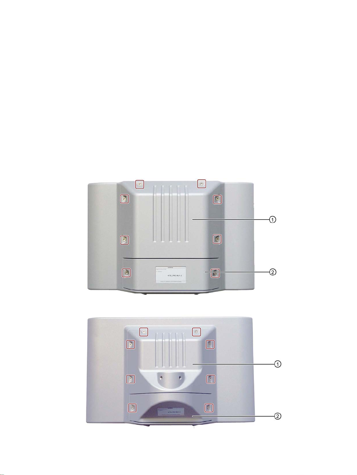
parameters
7
7.1
Opening and closing the backplane cover
Requirements
Opening the backplane cover
● The device is disconnected from the power supply.
● Torx TX20 screwdriver
SIMATIC IPC477E PRO
Operating Instructions, 08/2017, A5E39912462-AA
75
Page 76

Expanding the device and assigning the device parameters
NOTICE
Damaging the seal when opening
7.1 Opening and closing the backplane cover
If the device has not been opened for a long time, the backplane cover and terminal
compartment cover may stick to the enclosure due to the seal. Opening the device with
excessive force or with tools will destroy the seal. Spray and water jets as well as
penetrating substances can then damage the device.
Open the backplane cover and terminal compartment cover gently, without applying too
much pressure.
1. Loosen the two indicated M4x16 screws of the terminal compartment cover ② (the
screws are captive in the covers).
2. Open the connection compartment cover
② and set it safely aside. (see also section
"Power supply (Page 44)").
3. Remove the green connection terminal. The connection terminal is plugged in and can be
pulled out from the front.
4. Loosen the eight M4x16 screws of the backplane cover
① (the screws are captive in the
covers).
SIMATIC IPC477E PRO
76 Operating Instructions, 08/2017, A5E39912462-AA
Page 77

Expanding the device and assigning the device parameters
NOTICE
Damage to the device
7.1 Opening and closing the backplane cover
5. Open the backplane cover ①, gently open it 90° upwards and place it on the edge of the
enclosure, as shown below.
An SSD ② and power supply ④ are built into the backplane cover and connected to
the motherboard with short cables
completely or set it aside, you pull on the cables by their connectors. The device may be
damaged.
1. Secure the backplane cover
2. Pull out the cable connector
3. Unplug the power supply connector
6. Now you can install and remove the hardware.
③. If you open up the backplane cover ⑤
⑤ from falling down.
③ (see section "Replace SSD (Page 89)").
① on the motherboard.
SIMATIC IPC477E PRO
Operating Instructions, 08/2017, A5E39912462-AA
77
Page 78

Expanding the device and assigning the device parameters
Closing the backplane cover
Note
IP65 degree of protection at risk
If the seal on the backplane cover is damaged, the IP65 degree of protection is at risk.
The device must be repaired. Proceed as described in the section
(Page
Note
Do not exceed the permissible torque
If you tighten up the screws with a torque >
enclosure.
7.1 Opening and closing the backplane cover
1. Check that the seal is properly seated on the backplane cover.
Repair information
84).
2. Place the backplane cover on the enclosure. Make sure that no cables are crimped.
Secure the backplane cover from falling down.
3. Plug in the green connection terminal again.
4. Close the terminal compartment cover.
1.5 Nm, you could may the threading in the
5. Tighten the M4x16 screws of the backplane cover in crosswise order using a maximum
torque of 1.5 Nm. Check all screws again to ensure that the maximum torque of 1.5 Nm
has not been exceeded.
SIMATIC IPC477E PRO
78 Operating Instructions, 08/2017, A5E39912462-AA
Page 79

Expanding the device and assigning the device parameters
7.2
Installing and removing a memory module
Note
Use only the memory modules
information in the section "
Requirements
Procedure
NOTICE
ESD Directive
Removal
1. Press the marked latches towards the
outside.
The memory module tilts forward.
2. Pull the memory module out of the slot in
the direction of the arrow.
7.2 Installing and removing a memory module
The procedures for installing and removing the memory module are the same for all device
variants.
The motherboard is equipped with one slot for an SO-DIMM DDR4 memory module. You
can use it to expand the memory capacity of the device to a maximum of 16 GB.
recommended by Siemens AG. You can find additional
Accessories (Page 14)".
● The device is disconnected from the power supply.
● The device is open.
Note the protective measures required when working with ESD in the section "ESD
guideline (Page 108)".
SIMATIC IPC477E PRO
Operating Instructions, 08/2017, A5E39912462-AA
79
Page 80

Expanding the device and assigning the device parameters
Installation
1. Insert the memory module into the
marked slot at an incline with the contact
side toward the motherboard.
2. Carefully press the memory
the contact strip until the latches engage.
3. Close the device.
7.2 Installing and removing a memory module
module into
SIMATIC IPC477E PRO
80 Operating Instructions, 08/2017, A5E39912462-AA
Page 81

Expanding the device and assigning the device parameters
7.3
Installing and removing a CFast card
Note
Note the following points:
•
CFast card
•
CompactFlash cards (CF cards)
•
CFast card of the same
CFast cards
"Accessories (Page 14)".
Requirements
Procedure
Removal
1. For PRO device: Loosen the indicated
screws and remove the strain relief.
2. Press on the CFast card in the
of the arrow.
The CFast card moves approximately 5
mm out of the slot.
3. Remove the CFast card.
7.3 Installing and removing a CFast card
The procedures for installing and removing the CFast card are the same for all device
variants. Use only SIMATIC IPC CFast cards for industrial application.
Use the slot described here exclusively for a
Do not insert
Always replace the SIMATIC IPC CFast card with a SIMATIC IPC
production version or higher. For the SIMATIC IPC477E PRO, only SIMATIC
with production version 02 or higher may be used.
The production version can be found on the SIMATIC CFast card, see the section
.
into the slot for the CFast card.
● The device is disconnected from the power supply.
● The terminal compartment cover is open.
● SIMATIC IPC A CFast card that is approved for industrial use.
direction
SIMATIC IPC477E PRO
Operating Instructions, 08/2017, A5E39912462-AA
81
Page 82

Expanding the device and assigning the device parameters
Installation
Note
Carefully insert the CFast card into the slot without applying excess force.
1.
Insert the CFast card into the slot.
2.
Press the CFast card until it latches.
3.
Fasten the strain relief with the two screws.
5.
Close the device.
See also
7.4
Assigning CPU power consumption parameters
Operating mode
Description
The maximum CPU power consumption is 17 W.
setting.
optimized
constant CPU frequency.
The maximum power consumption of the CPU is 12 W.
7.4 Assigning CPU power consumption parameters
Replace SSD (Page 89)
The CPU can be switched to one of the following modes via a BIOS Setup setting (BIOS
setup > Menu "Power" > "Power&Performance" > "CPU Power Management Control" >
"CPU Power Level"):
Standard Default setting
The CPU clock is dynamically limited with maximum 3D graphics performance.
Performance
optimized
Determinism
Temperature
optimized
Setting the high performance for CPU and Graphics at the same time.
Especially for demanding 3D programs.
The maximum CPU power consumption is 25 W.
Note: The maximum permitted ambient temperature is reduced by 5° C with this
Same as standard, but additionally optimized for deterministic operation with
Setting for lowest power consumption.
The CPU clock is limited at a higher load.
SIMATIC IPC477E PRO
82 Operating Instructions, 08/2017, A5E39912462-AA
Page 83

8
8.1
Maintenance
Component
Replacement interval:
SSD / CFast card
Depends on the type of use 1
1
given.
To maintain high system availability, we recommend the preventative replacement of those
PC components that are subject to wear. The table below indicates the intervals for this
replacement.
CMOS backup battery 5 years
The interval for replacement depends greatly on the type of use. A specific interval cannot be
All drives are monitored with the software tools DiagBase or DiagMonitor on the basis of
their SMART status. As soon the SMART status of the SSD switches to "Not OK", a
message is sent in DiagBase or DiagMonitor, or when you start up the PC. You should then
back up your data and replace the drive.
SIMATIC IPC477E PRO
Operating Instructions, 08/2017, A5E39912462-AA
83
Page 84

Maintaining and repairing the device
8.2
Repair information
Making repairs
WARNING
Opening the device
Safety when working in and on electrical systems
Note
These safety steps
systems. Once work on an electrical system is finished, cancel the safety steps starting with
the last and finishing with the first.
8.2 Repair information
Install only system expansions approved for this device. If you install other expansion
devices, you may damage the device or violate the safety requirements and regulations on
RF suppression. Contact your technical support team or where you purchased your PC to
find out which system expansion devices may safely be installed.
Unauthorized opening and improper repairs on the device may result in substantial damage
to equipment or endanger the user. If you install or replace a system expansion and
damage your device, the warranty will become void.
The device may only be repaired by qualified personnel.
Work in or on electrical systems may only be carried out by authorized persons. The
following safety regulations apply in Germany for the prevention of electric shock and
electrocution:
1. Switch off the system
2. Secure the system to prevent it switching back on
3. Check the system to ensure it is de-energized
4. Ground and short the system
5. Cover or shield adjacent live parts
These safety rules are based on the DIN VDE 0105 standard.
must always be taken in the above order before any work on electrical
SIMATIC IPC477E PRO
84 Operating Instructions, 08/2017, A5E39912462-AA
Page 85

Maintaining and repairing the device
CAUTION
Electrostatic-sensitive components
WARNING
Risk of explosion and release of harmful substances
NOTICE
Batteries and rechargeables pollute the environment
8.2 Repair information
In accordance with the applicable safety regulations, clearly indicate on an electrical system
that work on it is underway.
Observe the safety regulations applicable in the country of operation.
The device contains electronic components which are destroyed by electrostatic charges.
This can result in malfunctions and damage to the machine or plant.
Make sure you take precautionary measures even when you open the device, for example,
when opening device doors, device covers or the housing cover. For more information,
refer to the section "ESD Guideline"
Improper handling of lithium batteries can result in an explosion of the batteries. Explosion
of the batteries and the released pollutants can cause severe physical injury.
Observe all safety and handling instructions for lithium batteries. Do not expose lithium
batteries to flames and do not solder the battery cell. Do not recharge, open, or short
lithium batteries. Do not reverse lithium battery polarity or heat the batteries to over 100°C.
Keep lithium batteries out of direct sunlight and protect them from moisture and
condensation.
Note the following when handling lithium batteries:
● A worn battery jeopardizes the function of the device. Change the battery in good time.
● Replace the lithium battery only with batteries of the same type or a type recommended
by SIEMENS.
The article number for the lithium battery is A5E34734290.
Do not dispose of used batteries or rechargeables in household waste. Users are obliged
by law to return used batteries and rechargeable batteries. You as the user are legally
responsible disposing used batteries or rechargeables in a correct manner.
Observe the following rules for the disposal of batteries and rechargeables:
• Dispose of used batteries and rechargeable batteries separately as hazardous waste in
accordance with local regulations.
• You can take used batteries and rechargeable batteries to public collection points and
wherever batteries and rechargeable batteries of the type in question are sold.
• Mark used battery containers as "Used batteries".
SIMATIC IPC477E PRO
Operating Instructions, 08/2017, A5E39912462-AA
85
Page 86

Maintaining and repairing the device
Limitation of liability
8.2 Repair information
All technical specifications and approvals for the device apply only if you use expansion
components that have a valid CE approval (CE marking). The installation instructions for
expansion components in the associated documentation must be observed.
UL approval of the device only applies when the UL-approved components are used
according to their "Conditions of Acceptability".
We are not liable for functional limitations caused by the use of third-party devices or
components.
SIMATIC IPC477E PRO
86 Operating Instructions, 08/2017, A5E39912462-AA
Page 87

Maintaining and repairing the device
8.3
Cleaning the Device Front
CAUTION
Unwanted reactions when cleaning the device
Cleaning Agents
NOTICE
Damage to the HMI device caused by impermissible cleaning agents
Procedure
8.3 Cleaning the Device Front
The device is designed for low-maintenance operation. You should still clean the device front
regularly, however.
You risk unintentional actuation of control elements if you clean the device while it is
switched on.
You may possibly trigger unwanted actions of the device or controller that are liable to
cause personal injury or damage to the machinery.
Always switch off the device before you clean it.
Impermissible and unsuitable cleaning agents may cause damage to the HMI device.
Use dish soap or foaming screen cleaner only as cleaning agents. Do not use the following
cleaning agents:
• Aggressive solvents or scouring powder
• Steam jets
• Compressed air
1. Switch off the device.
2. Dampen the cleaning cloth.
3. Spray the cleaning agent on the cloth and not directly on the device.
4. Clean the device with the cleaning cloth.
SIMATIC IPC477E PRO
Operating Instructions, 08/2017, A5E39912462-AA
87
Page 88

Maintaining and repairing the device
8.4
Installing and removing hardware
8.4.1
Replacing the backup battery
Requirements
Procedure
NOTICE
Time setting is lost
Note
Writing down the BIOS settings
Make a note of the current BIOS setup settings or save them as a
setup Exit menu. You will find a list for noting the settings in the BIOS description.
1.
Remove the labeled connector.
2. The battery is fastened with a
fastener.
Grip the labeled battery and carefully pull
it out.
8.4 Installing and removing hardware
● The device is disconnected from the power supply.
● The power supply connector is pulled out.
● The device is open, see the section "Opening and closing the backplane cover
(Page 75)".
● A replacement battery is included
The time and the setup settings are deleted if it takes longer than 30 seconds to replace the
battery. The device is no longer synchronized. Time-controlled programs will no longer run
or will run at the wrong time. This may damage the plant.
Set the device time again.
user profile in the BIOS
Velcro
For installation, proceed in the reverse order and reconnect the device.
SIMATIC IPC477E PRO
88 Operating Instructions, 08/2017, A5E39912462-AA
Page 89

Maintaining and repairing the device
8.4.2
Replace SSD
Requirements
Procedure
1.
Pull out the connectors
Take into account the safety latch of the
cable in doing so.
2.
Set the backplane cover down flat.
3. Remove the indicated screws and firmly
hold down the cover
supply.
4. Remove the drive cage with the SSD and
power supply and place it with the back
facing up.
8.4 Installing and removing hardware
● The device is disconnected from the power supply.
● The device is open, see the section "Opening and closing the backplane cover
(Page 75)".
● An SSD is installed in the backplane cover.
● T10 screwdriver
①, ② and ③.
④ of the power
SIMATIC IPC477E PRO
Operating Instructions, 08/2017, A5E39912462-AA
89
Page 90
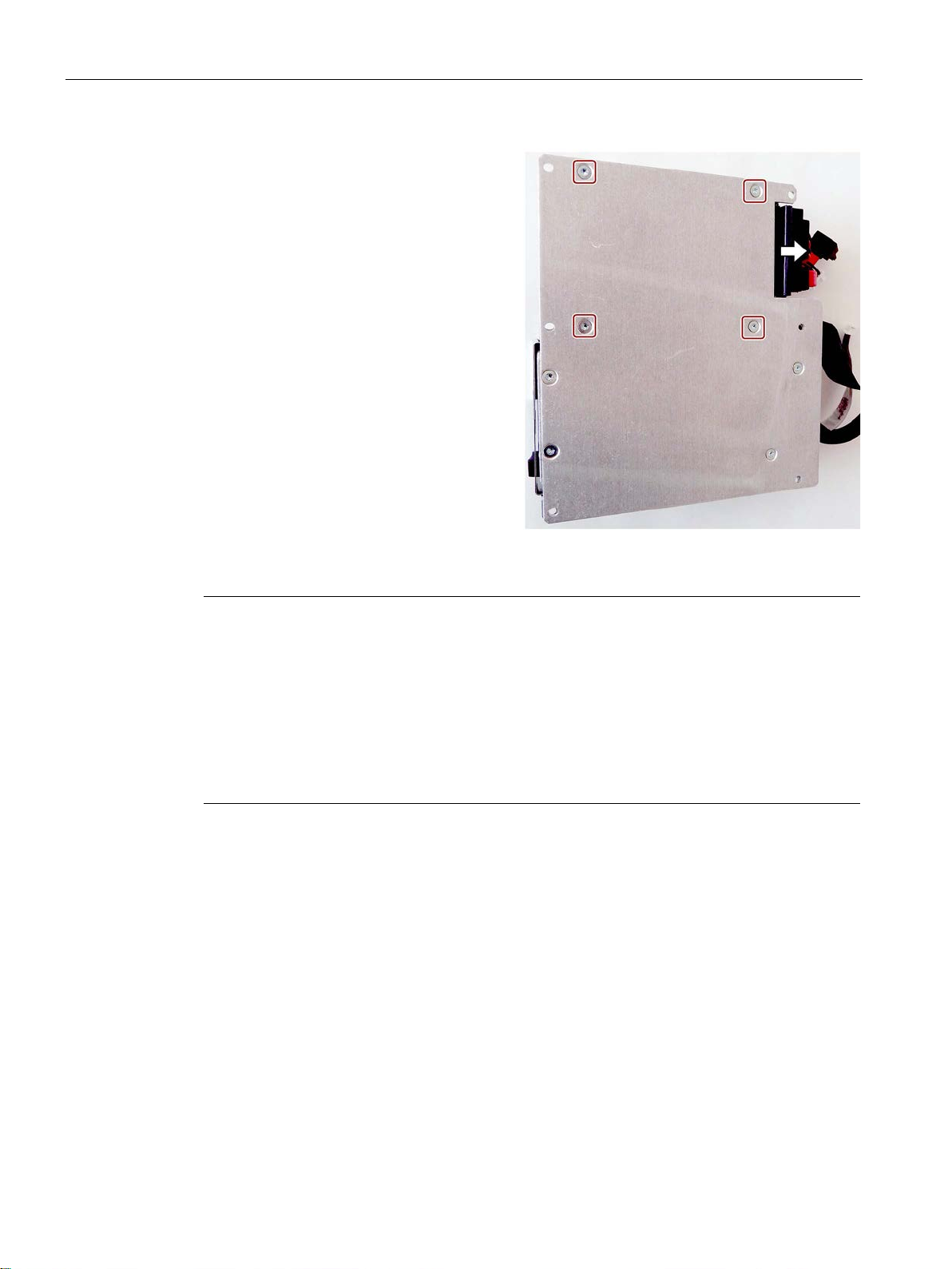
Maintaining and repairing the device
5. Remove the indicated countersunk
screws on the back.
6.
Remove the SSD.
7. Pull out the SSD connector from the i
te
Installation
Note
Do not exceed the maximum permissible torques
If you tighten the screws with too much torque, the threading in enclosure and drive cage
may be damaged. Note the maximum permitted torques:
0.8
•
0.5
•
8.4 Installing and removing hardware
n-
rface.
Nm for the following connections:
M3 x 5 pan-head screws for mounting the drive cage in the backplane cover
Nm for the following connections:
M3 x 5 countersunk screws for mounting the SSD drive in the drive cage
Proceed in reverse order for the installation.
1. In step 1 above, ensure that the connectors are not installed with reverse polarity.
2. Close the device.
SIMATIC IPC477E PRO
90 Operating Instructions, 08/2017, A5E39912462-AA
Page 91

Maintaining and repairing the device
8.5
Installing the software
8.5.1
Reinstalling the operating system
8.5.1.1
General installation procedure
Note
Installing the operating system in UEFI mode
To
UEFI mode. Since Windows Embedded operating systems are installed in MBR mode, the
USB flash drive must be booted for the Restore function in Legacy mode.
Note
GPT partitioning with Windows 10
Please note that GPT partitioning should be selected for Windows 10 (GPT: GUID Partition
Table).
Recovery function (only with Windows 7 Ultimate and Windows 10)
NOTICE
Windows Embedded
Contents of the "DocuAndDrivers" directory
Restore function
8.5 Installing the software
If your operating system is no longer functioning correctly, you can reinstall it in one of two
ways:
● With the Recovery function of the supplied USB flash drive
● With the Restore function of the supplied USB flash drive
The USB flash drive is set up as bootable for these functions. For this purpose, "USB Boot"
must be set to "enabled" in the BIOS Setup.
install an operating system in UEFI mode, the USB flash drive must also be booted in
The Recovery function is not available for Windows Embedded operating systems.
The supplied USB contains the installation program with tools for configuring the drives and
installing the operating system with the supported languages.
The basic language of the installed operating system is English. To add other languages,
install these languages from the supplied USB flash drive (Documentation and Drivers).
The supplied USB flash drive contains the documentation, hardware drivers and updates.
In Windows, these contents are available via a menu.
If you have ordered IPC477E PRO with operating system, the supplied USB flash drive
contains the Restore function.
SIMATIC IPC477E PRO
Operating Instructions, 08/2017, A5E39912462-AA
91
Page 92

Maintaining and repairing the device
8.5.1.2
Restoring the factory state of the software
NOTICE
Data are deleted
Procedure
Note
The "USB Boot" option has to be set to "Enabled" in the BIOS
device can boot from the USB flash drive.
8.5 Installing the software
You can restore the original factory software using the Restore function. The USB flash drive
contains the necessary images and tools for transferring the factory software to the SSD or
memory card of your PC. The following options are available for restoring software:
● Restoring the entire SSD or memory card with drive C: (system) and drive D: Use the
"Restore entire hard disk" option.
● Restore drive C: only This allows you to retain any user data on drive D: Use the "Restore
system partition only" option.
When you select the "Restore entire hard disk" option, all data, user settings and
authorizations or license keys on the hard disk are lost. The hard disk is reset to the
delivery state with partitions "C:" and "D:".
If the "Restore system partition only" option is set, all files on drive C: (System) are deleted.
All data, user settings and existing authorizations or license keys on drive "C:" will be lost.
Drive "C:" on the hard drive is completely erased, reformatted and the original software is
written to it.
menu "Boot" so that the
1. Connect the USB flash drive to the device.
2. Restart the device.
3. Press <ESC> when the following BIOS message appears:
Press ESC for boot options
The BIOS selection menu is displayed when initialization is completed.
4. To boot from the USB flash drive, select the Boot Manager.
5. Select the USB flash drive in the Boot Manager and confirm the entry.
6. Select the Restore function and confirm the entry.
7. Follow the on-screen instructions.
SIMATIC IPC477E PRO
92 Operating Instructions, 08/2017, A5E39912462-AA
Page 93

Maintaining and repairing the device
8.5.1.3
Windows
Note
WIN 10
Specific information on using the Windows
manuals (not included in the product package):
•
•
•
Note
WIN 7
Specific information on using the Windows
manual (not included in the product package): Microsoft Windows 7
(MS Press No.
Requirement
Procedure
Note
The "USB Boot" option has to be set to
device to boot from the USB stick.
8.5 Installing the software
operating systems is available in the following
Windows 10 - Step by Step (MS Press No. 324)
Windows 10 Plain and Simple (MS Press No. 422)
Windows 10 Inside Out (MS Press No. 325 / MS Press No. 418)
operating systems is available in the following
- Technical Reference
5927).
● USB keyboard and monitor
● USB stick provided with Recovery function for the operating system ordered
"Enabled" in the BIOS menu "Boot" to allow the
1. Connect the USB stick to the device.
2. Restart the device.
3. Press <ESC> when the following BIOS message appears:
Press ESC for boot options
The BIOS selection menu is displayed when initialization is completed.
4. To boot from the USB stick, select the Boot Manager.
5. Select the USB stick in the Boot Manager and confirm the entry.
6. Select the Recovery function and confirm the entry.
SIMATIC IPC477E PRO
Operating Instructions, 08/2017, A5E39912462-AA
93
Page 94

Maintaining and repairing the device
NOTICE
Data deleted
"Install Windows" installation program
Setting up partitions under Windows
Setting up the language selection by means of the Multilanguage User Interface (MUI)
8.5 Installing the software
7. Follow the on-screen instructions.
After a few seconds, you will see the "Install Windows" installation program.
All data, user settings and existing authorizations or license keys on drive C: are deleted
during the installation of Windows .
• Back up all data.
• Check the data and time in the BIOS setup, "Main" menu and correct the displayed
time if necessary.
8. Now follow the instructions of the installation program "Install Windows". You will find
additional information in the operating system manual.
The language of the installation program and the operating system you want to install has
been preset to English. You can change the language of the operating system after the
installation. You can find information on this in section: "Setting up the language selection by
means of the Multilanguage User Interface (MUI)".
You can set up partitions during the installation process.
The recommended minimum size for Windows system partition varies, depending on the
amount of RAM and additional software that you are going to use. Information about the
partitioning of the data volume in the delivery state is available in "Partitioning in Windows 7
Ultimate (Page 99)".
You can set the display of menus, dialogs or other information, such as date and time, to a
different language. For this purpose, you can either select one of the preinstalled languages
or install a new language package.
The following command sequences are described in English. Depending on the default
setting, they can be displayed in another language.
SIMATIC IPC477E PRO
94 Operating Instructions, 08/2017, A5E39912462-AA
Page 95

Maintaining and repairing the device
Setting up language selection
Note
WIN 10
Specific information on using the Windows
manuals (not included in the product package):
•
•
•
Note
WIN 7
Specific information on setting up the language selection for Windows operating systems can
be found in the manual "Microsoft Windows 7, Technical Reference (MS Press No. MSE
5927)", not included in the
Changing the settings for language, region and formats of a registered user account
Changing the settings for language, region and formats of the system account and the
standard user account
8.5 Installing the software
operating systems is available in the following
Windows 10 - Step by Step (MS Press No. 324)
Windows 10 Plain and Simple (MS Press No. 422)
Windows 10 Inside Out (MS Press No. 325 / MS Press No. 418)
-
scope of delivery.
1. Choose:
"Start > Control Panel > Clock, Language, and Region > Regional and Language
Options"
2. You can make the desired changes in the "Formats", "Location" and "Keyboards and
Languages" tabs.
You can change the settings for language, region and formats of the system account (for
example, the language in the user login dialog) and the settings of the standard user account
(standard setting for new users). The settings of the registered user are copied to the system
account and the standard user account for this purpose.
1. Choose:
"Start > Control Panel > Clock, Language, and Region > Regional and Language
Options"
2. You can make the required changes in the "Administrative" tab. You copy the settings by
clicking the respective button.
SIMATIC IPC477E PRO
Operating Instructions, 08/2017, A5E39912462-AA
95
Page 96

Maintaining and repairing the device
Installing new language packages
The following languages can be installed at a later time:
Language
Windows
German
X
English
X
French
X
Spanish
X
Chinese (Hong Kong)
X
Chinese (simplified)
X
Chinese (Taiwan)
X
Japanese
X
Russian
X
8.5 Installing the software
Some language packages are available on the Recovery section of the USB stick in the
"Language packs" folder.
1. Choose:
"Start > Control Panel > Clock, Language, and Region > Regional and Language
Options"
2. Select the "Keyboards and Languages" tab.
3. Click the "Install/uninstall languages" button and make the required changes.
Italian X
SIMATIC IPC477E PRO
96 Operating Instructions, 08/2017, A5E39912462-AA
Page 97

Maintaining and repairing the device
8.5.1.4
Windows Embedded Standard
Note
You require a USB keyboard and the supplied USB flash drive to reinstall the operating
system. Before performing the new installation, you should check the date and time set in
the BIOS Setup, "Main" menu, and correct these
Procedure - Changing the system language
Note
Note the license terms of Windows Embedded Standard 7
Note the license terms for Windows Embedded Standard
software terms of the Siemens
You can find the license terms in the delivered document "MICROSOFT SOFTWARE
LICENSE TERMS for Windows
\
Procedure - Changing the system language
8.5 Installing the software
If your software becomes corrupt for any reason, you can re-install it using the USB stick
provided. The USB flash drive contains an image file for the device memory with the original
software package (operating system with installed hardware drivers).
You can change the language using the supplied USB flash drive. The USB stick contains
the required language packages and help for changing the system language.
if necessary.
7 and especially the extended
AG.
Windows\System32\license.rtf.
1. Connect the supplied USB flash drive to a free USB port of the device.
2. Restart the device and press "ESC" to access the BIOS.
3. Switch to the "Boot" menu and select the setting "USB Boot" = "Enabled".
4. Switch to the "Exit" menu and select "Exit Saving Changes".
5. Restart the device and press the "ESC" key and then enter the "Boot Manager" menu.
6. Select the USB flash drive and press "Enter" to boot from this.
7. Follow the instructions on the screen.
8. After selecting the menu dialog language, select the menu item "Manage language
packages".
Depending on the current language setup, you have the following options in the "Manage
language packages" menu:
– Display language settings
– Install language
Embedded Standard 7" and in the system drive under
– Change language
– Uninstall installed language
SIMATIC IPC477E PRO
Operating Instructions, 08/2017, A5E39912462-AA
97
Page 98

Maintaining and repairing the device
8.5.2
Partitioning the data storage medium
8.5.2.1
Partitioning in Windows Embedded Standard 7
Partitioning of the SIMATIC IPC CFast card
Partition
Name
Size of the card
File system
8 GB
16 GB
30 GB
mainder
mainder
mainder
Partition
Name
Size of the card
File system
8 GB
16 GB
30 GB
First
SYSTEM
7 GB
12 GB
30 GB
NTFS (not compressed)
mainder
mainder
mainder
Partitioning of the SSD
Partition
Name
Size of data medium
File system
>100 GB
>100 GB
Primary
SYSTEM
60 GB
100 GB
NTFS not compressed
Second
DATA
Remainder
Remainder
NTFS not compressed
SIMATIC IPC Image & Partition Creator.
8.5 Installing the software
You will need to reconfigure the partitions after installing a new drive, to repair corrupt
partitions or to change the partitioning.
The SIMATIC IPC CFast card for Windows Embedded Standard 7 comes configured with
the following default partitions:
Table 8- 1 32-bit version of the operating system
First SYSTEM 6 GB 12 GB 30 GB NTFS (not compressed)
Second DATA Re-
* Due to partitioning/formatting, the actual CFast capacity does not correspond to the
memory size specified on the SIMATIC IPC CFast card.
Table 8- 2 64-bit version of the operating system
Re-
Re-
NTFS (not compressed)
SIMATIC IPC477E PRO
98 Operating Instructions, 08/2017, A5E39912462-AA
Second DATA Re-
Re-
Re-
NTFS (not compressed)
* Due to partitioning/formatting, the actual CFast capacity does not correspond to the
memory size specified on the SIMATIC IPC CFast card.
The following partitions are configured in the delivery state of the SSD with Windows
Embedded Standard 7:
To restore the partitions to their original delivery state, we recommend you use the software
Additional information is available in the
accompanying documentation.
Page 99

Maintaining and repairing the device
8.5.2.2
Partitioning in Windows 7 Ultimate
Partitioning of the HDD or SSD
Partition
Name
Size of data medium
File system
< 54 GB
>54 GB
>100 GB
program
Second
System
40 GB
50 GB
100 GB
NTFS not compressed
8.5.2.3
Changing the partitions under Windows 7 and Windows 10
Note
Data lost in the case of deleting a partition!
If you delete a partition, all the data on this partition is lost.
Back up your data before you change partitions.
Requirement
Procedure - Reduce partition
8.5 Installing the software
You will need to reconfigure the partitions after installing a new drive, to repair corrupt
partitions or to change the partitioning.
In delivery state, the following default partitions are set up on the HDD or SSD for the
Windows 7 Ultimate operating system:
Primary Boot 100 MB 100 MB 100 MB Automatically set up by installation
Third Data Remainder Remainder Remainder NTFS not compressed
With the disk management, you can adapt the partitioning of your drives.
You can reduce or delete an available partition to acquire unassigned memory space, which
you can use to set up a new partition or to increase an existing partition.
You are logged on as an administrator.
A partition can only be reduced if sufficient space is available.
1. Click with the right mouse button on the partition to be reduced and click on "Reduce
size".
2. Follow the instructions.
SIMATIC IPC477E PRO
Operating Instructions, 08/2017, A5E39912462-AA
99
Page 100

Maintaining and repairing the device
Procedure - Increase partition
Note
To increase a partition, this partition must not be formatted with a file system or the partition
must be formatted with an "NTFS" file system.
8.5.3
Installing drivers and software
Note
Set country settings to English (US)
In the case of
dialogs and the default language to English (US) in the regional settings before new drivers
and operating system updates are installed.
You can install a second language package for
supplied USB flash drive under Windows Embedded Standard 7.
Procedure
Note
For a new installation of Windows operating systems, the chipset d
before all other drivers, if required.
8.5 Installing the software
1. Click in the partition manager with the right mouse button on the partition to be increased
and click on "Increase size".
2. Follow the instructions on the screen.
Additional information is available in the "Help" menu under "Help topics" and "Search".
multilingual operating systems (MUI versions), you must set the menus and
service purposes at a later time with the
1. Connect the supplied USB flash drive to the USB port.
2. Start the program "START_DocuAndDrivers".
3. Select "Drivers" in the index.
4. Select the device and operating system.
5. Select the desired driver
6. Open the folder with the driver information: Click on the link next to "Driver path".
7. Start the setup program in this folder.
river must be installed
SIMATIC IPC477E PRO
100 Operating Instructions, 08/2017, A5E39912462-AA
 Loading...