

Siemens SIMATIC IPC477E Operating Instructions Manual

___________________
___________________
___________________
___________________
___________________
___________________
___________________
___________________
___________________
___________________
___________________
___________________
SIMATIC
Industrial PC
SIMATIC IPC477E
Operating Instructions
12/2016
A5E37455003
Preface
Overview
1
Safety instructions
2
Mounting and connecting the
device
3
Commissioning the device
4
Operating the device and
device functions
5
Expanding the device and
assigning device parameters
6
Maintaining and servicing
your device
7
Technical information
8
Technical support
A
Markings and symbols
B
List of abbreviations
C
-AB

Siemens AG
Division Digital Factory
Postfach 48 48
90026 NÜRNBERG
GERMANY
A5E37455003-AB
Ⓟ
Copyright © Siemens AG 2016.
All rights reserved
Legal information
Warning notice system
DANGER
indicates that death or severe personal injury will result if proper precautions are not taken.
WARNING
indicates that death or severe personal injury may result if proper precautions are not taken.
CAUTION
indicates that minor personal injury can result if proper precautions are not taken.
NOTICE
indicates that property damage can result if proper precautions are not taken.
Qualified Personnel
personnel qualified
Proper use of Siemens products
WARNING
Siemens products may only be used for the applications described in the catalog and in the relevant technical
ambient conditions must be complied with. The information in the relevant documentation must be observed.
Trademarks
Disclaimer of Liability
This manual contains notices you have to observe in order to ensure your personal safety, as well as to prevent
damage to property. The notices referring to your personal safety are highlighted in the manual by a safety alert
symbol, notices referring only to property damage have no safety alert symbol. These notices shown below are
graded according to the degree of danger.
If more than one degree of danger is present, the warning notice representing the highest degree of danger will
be used. A notice warning of injury to persons with a safety alert symbol may also include a warning relating to
property damage.
The product/system described in this documentation may be operated only by
task in accordance with the relevant documentation, in particular its warning notices and safety instructions.
Qualified personnel are those who, based on their training and experience, are capable of identifying risks and
avoiding potential hazards when working with these products/systems.
Note the following:
for the specific
documentation. If products and components from other manufacturers are used, these must be recommended
or approved by Siemens. Proper transport, storage, installation, assembly, commissioning, operation and
maintenance are required to ensure that the products operate safely and without any problems. The permissible
All names identified by ® are registered trademarks of Siemens AG. The remaining trademarks in this publication
may be trademarks whose use by third parties for their own purposes could violate the rights of the owner.
We have reviewed the contents of this publication to ensure consistency with the hardware and software
described. Since variance cannot be precluded entirely, we cannot guarantee full consistency. However, the
information in this publication is reviewed regularly and any necessary corrections are included in subsequent
editions.
12/2016 Subject to change

Preface
Purpose of the Operating Instructions
Basic knowledge required
Scope of the operating instructions
Scope of this documentation
These operating instructions contain all the information you need for commissioning and
operating the SIMATIC IPC477E.
It is intended both for programming and testing personnel who commission the device and
connect it with other units (automation systems, programming devices), as well as for service
and maintenance personnel who install add-ons or carry out fault/error analyses.
A solid background in personal computers and Microsoft operating systems is required to
understand this manual. General knowledge in the field automation control engineering is
recommended.
These operating instructions apply to "SIMATIC IPC477E" industrial PCs with article
numbers 6AV7241... (built-in unit).
The documentation for the IPC includes the following:
● Product information, e.g. "Important notes on your device"
● Quick Install Guide SIMATIC IPC477E
● SIMATIC IPC477E Operating Instructions
The documentation is supplied with the IPC in multiple languages as PDF on the USB stick
supplied in the documentation package.
SIMATIC IPC477E
Operating Instructions, 12/2016, A5E37455003-AB
3

Preface
Conventions
Note
A note is important information about the product, handling the product or a reference to
specific sections of the
History
Edition
Comments
10/2016
First edition
12/2016
Amendment to the multi-touch devices
In these operating instructions, "device" is used as the standard term for
"SIMATIC IPC477E" (built-in unit).
In these operating instructions, the terms "Windows Embedded Standard 7 P" and
"Windows Embedded Standard 7 E" are also abbreviated with the term "Windows
Embedded Standard". "Windows 7" is used as an abbreviation for "Windows 7 Ultimate".
A touch device generally refers to a device with a capacitive multi-touch screen or a resistive
single touch screen. Touch screen is the general term for a resistive single touch screen or a
capacitive multi-touch screen.
documentation that require special consideration.
The following editions of these operating instructions have already been published:
SIMATIC IPC477E
4 Operating Instructions, 12/2016, A5E37455003-AB

Table of contents
Preface ...................................................................................................................................................... 3
1 Overview .................................................................................................................................................... 9
2 Safety instructions ................................................................................................................................... 19
3 Mounting and connecting the device........................................................................................................ 25
1.1 Product description ................................................................................................................... 9
1.2 Design of the built-in units ...................................................................................................... 12
1.2.1 Devices with resistive single touch screen ............................................................................. 12
1.2.2 Devices with capacitive multi-touch screen ............................................................................ 13
1.2.3 Devices with expansions ........................................................................................................ 14
1.2.3.1 Devices with PCIe card ........................................................................................................... 14
1.2.4 Interfaces and operator controls for devices with 24 V DC power supply .............................. 15
1.2.5 Interfaces and operator controls for devices with 100-240 V AC power supply ..................... 15
1.3 Accessory kit ........................................................................................................................... 16
1.4 Accessories ............................................................................................................................. 16
2.1 General safety instructions ..................................................................................................... 19
2.2 Notes on usage ....................................................................................................................... 22
3.1 Preparing for mounting ........................................................................................................... 25
3.1.1 Checking the delivery package ............................................................................................... 25
3.1.2 Device identification data ........................................................................................................ 27
3.1.3 Built-in unit .............................................................................................................................. 29
3.1.3.1 Permitted mounting positions ................................................................................................. 29
3.1.3.2 Preparing the mounting cutout ................................................................................................ 31
3.2 Installing the built-in unit ......................................................................................................... 33
3.2.1 Installation guidelines ............................................................................................................. 33
3.2.2 Mounting clips or mounting brackets, position for IP65-compliant installation ....................... 35
3.2.3 Mounting the device with mounting clips ................................................................................ 36
3.2.4 Mounting the device with mounting brackets .......................................................................... 38
3.2.5 Position of the mounting clips for IP66-complaint installation ................................................ 40
3.3 Connecting the device ............................................................................................................ 41
3.3.1 Notes on connecting ............................................................................................................... 41
3.3.2 Power supply built-in unit ........................................................................................................ 43
3.3.2.1 Connecting the protective earth .............................................................................................. 43
3.3.2.2 Connect 100-240 VAC power supply ...................................................................................... 45
3.3.2.3 Connecting the terminal .......................................................................................................... 48
3.3.2.4 Connecting the 24 V DC power supply ................................................................................... 49
3.3.3 Connecting peripheral equipment ........................................................................................... 51
3.3.4 Connecting the device to networks ......................................................................................... 52
3.3.5 Securing cables on the built-in unit ......................................................................................... 53
3.3.5.1 Attaching the strain relief ........................................................................................................ 53
SIMATIC IPC477E
Operating Instructions, 12/2016, A5E37455003-AB
5

Table of contents
4 Commissioning the device ....................................................................................................................... 57
5 Operating the device and device functions .............................................................................................. 61
6 Expanding the device and assigning device parameters ......................................................................... 79
7 Maintaining and servicing your device ..................................................................................................... 87
4.1 General information on commissioning ................................................................................. 57
4.2 Initial commissioning .............................................................................................................. 58
4.3 Windows Action Center .......................................................................................................... 60
5.1 Operator input options ........................................................................................................... 61
5.2 Operating a device with resistive single touch screen ........................................................... 62
5.3 Operating a device with capacitive multi-touch screen .......................................................... 63
5.4 IPC Driver and Tools .............................................................................................................. 65
5.5 Extended device functions ..................................................................................................... 66
5.5.1 Monitoring functions ............................................................................................................... 66
5.5.1.1 Overview of the monitoring functions ..................................................................................... 66
5.5.1.2 Temperature monitoring/display ............................................................................................ 67
5.5.1.3 Watchdog (WD) ...................................................................................................................... 68
5.5.1.4 Battery monitoring .................................................................................................................. 69
5.5.1.5 Mass storage monitoring ........................................................................................................ 69
5.5.2 Enhanced Write Filter (EWF) ................................................................................................. 70
5.5.3 File Based Write Filter (FBWF) .............................................................................................. 73
5.5.4 Buffer memory NVRAM ......................................................................................................... 74
5.5.5 Active Management Technology (AMT) ................................................................................ 75
5.5.6 Trusted Platform Modul (TPM) ............................................................................................... 77
6.1 Opening the device ................................................................................................................ 79
6.1.1 Opening the built-in unit ......................................................................................................... 79
6.2 Installing and removing a memory module ............................................................................ 81
6.3 Installing and removing a PCIe card (built-in units with PCIe card) ....................................... 83
6.4 Installing and removing a CFast card .................................................................................... 85
6.4.1 Installing and removing a CFast card (external slot) ............................................................. 85
6.5 Assigning CPU power consumption parameters ................................................................... 86
7.1 Maintenance ........................................................................................................................... 87
7.2 Repair information .................................................................................................................. 87
7.3 Cleaning the Device Front ..................................................................................................... 90
7.4 Installing and removing hardware .......................................................................................... 91
7.4.1 Built-in unit ............................................................................................................................. 91
7.4.1.1 Replacing back-up battery (devices with 15", 19" or 22" display) .......................................... 91
7.4.1.2 Replacing the SSD (devices with 15", 19" or 22" display) ..................................................... 93
7.4.1.3 Replacing HDD ...................................................................................................................... 95
SIMATIC IPC477E
6 Operating Instructions, 12/2016, A5E37455003-AB

Table of contents
8 Technical information ............................................................................................................................. 111
7.5 Installing the software ............................................................................................................. 97
7.5.1 Reinstalling the operating system ........................................................................................... 97
7.5.1.1 General installation procedure ................................................................................................ 97
7.5.1.2 Restoring the delivery state .................................................................................................... 98
7.5.1.3 Windows 7 .............................................................................................................................. 99
7.5.1.4 Windows Embedded Standard 7 .......................................................................................... 103
7.5.2 Partitioning data media ......................................................................................................... 105
7.5.2.1 Partitioning in Windows Embedded Standard 7 ................................................................... 105
7.5.2.2 Partitioning in Windows 7 Ultimate ....................................................................................... 106
7.5.2.3 Adapting partitions in Windows 7 Ultimate and Windows Embedded Standard 7 ............... 106
7.5.3 Installing drivers and software .............................................................................................. 108
7.5.4 Update installation ................................................................................................................ 109
7.5.4.1 Updating the operating system ............................................................................................. 109
7.5.4.2 Installing or updating application programs and drivers ....................................................... 109
7.5.5 Backing up data .................................................................................................................... 109
7.6 Recycling and disposal ......................................................................................................... 109
8.1 Certificates and approvals .................................................................................................... 111
8.2 Directives and declarations ................................................................................................... 113
8.2.1 Electromagnetic compatibility ............................................................................................... 113
8.2.2 ESD guideline ....................................................................................................................... 114
8.3 Dimension drawings.............................................................................................................. 117
8.3.1 Dimension drawing of 15" device with capacitive multi-touch screen .................................. 117
8.3.2 Dimension drawing of 19" device with capacitive multi-touch screen .................................. 119
8.3.3 Dimension drawing of 22" device with capacitive multi-touch screen .................................. 121
8.3.4 Dimension drawing of 15" device with resistive single-touch screen ................................... 123
8.3.5 Dimension drawing of 19" device with resistive single-touch screen ................................... 125
8.3.6 Dimension drawing of 22" device with resistive single-touch screen ................................... 127
8.4 Technical specifications ........................................................................................................ 129
8.4.1 Built-in unit ............................................................................................................................ 129
8.4.1.1 General technical specifications ........................................................................................... 129
8.4.1.2 Environmental conditions ...................................................................................................... 133
8.4.2 Power requirements of the components ............................................................................... 135
8.4.3 Integrated DC power supply ................................................................................................. 135
8.4.4 AC voltage supply ................................................................................................................. 136
8.5 Hardware descriptions .......................................................................................................... 137
8.5.1 External ports ........................................................................................................................ 137
8.5.1.1 Serial interface ...................................................................................................................... 137
8.5.1.2 CFast .................................................................................................................................... 138
8.5.1.3 DisplayPort ............................................................................................................................ 139
8.5.1.4 Ethernet ................................................................................................................................ 140
8.5.1.5 USB 3.0 port ......................................................................................................................... 140
8.5.1.6 USB 2.0 ................................................................................................................................. 141
8.5.2 Internal ports ......................................................................................................................... 142
8.5.2.1 PCIe card .............................................................................................................................. 142
8.5.3 System resources ................................................................................................................. 144
8.5.3.1 Currently allocated system resources ................................................................................... 144
8.5.3.2 Assignment of system resources .......................................................................................... 144
SIMATIC IPC477E
Operating Instructions, 12/2016, A5E37455003-AB
7

Table of contents
A Technical support .................................................................................................................................. 163
B Markings and symbols ........................................................................................................................... 167
C List of abbreviations ............................................................................................................................... 171
Glossary ................................................................................................................................................ 177
Index ...................................................................................................................................................... 185
8.5.4 I/O Address Areas ................................................................................................................ 146
8.5.4.1 Overview of the internal module registers ........................................................................... 146
8.5.4.2 Watchdog trigger register (read only, address 066h) .......................................................... 146
8.5.4.3 Watchdog enable register / 066h select register (read/write, address 062h) ...................... 146
8.5.4.4 Battery status register (read-only, address 50Ch) ............................................................... 147
8.5.4.5 NVRAM address register ..................................................................................................... 147
8.6 BIOS description .................................................................................................................. 148
8.6.1 Overview .............................................................................................................................. 148
8.6.2 Opening the BIOS selection menu....................................................................................... 149
8.6.3 Structure of the BIOS Setup menu ...................................................................................... 151
8.6.4 Exit menu ............................................................................................................................. 153
8.6.5 BIOS update ......................................................................................................................... 154
8.6.6 Alarm, error and system messages ..................................................................................... 155
8.7 Active Management Technology (AMT) .............................................................................. 156
8.7.1 Introduction .......................................................................................................................... 156
8.7.2 Overview of AMT.................................................................................................................. 157
8.7.3 Enabling Intel® AMT / basic configuration ........................................................................... 157
8.7.4 Resetting the Intel® AMT to the default settings and disabling AMT .................................. 159
8.7.5 Determining the network address ........................................................................................ 159
8.7.6 Forcing user consent ........................................................................................................... 160
8.8 Functional scope in Windows .............................................................................................. 160
8.8.1 Windows Embedded Standard 7 ......................................................................................... 160
A.1 Service and support ............................................................................................................. 163
A.2 Problem solving .................................................................................................................... 164
A.3 Notes on the use of third-party modules .............................................................................. 165
B.1 Overview .............................................................................................................................. 167
B.2 Safety ................................................................................................................................... 167
B.3 Operator controls ................................................................................................................. 167
B.4 Certificates, approvals and markings ................................................................................... 168
B.5 Interfaces ............................................................................................................................. 168
SIMATIC IPC477E
8 Operating Instructions, 12/2016, A5E37455003-AB
1
1.1
Product description
Figure 1-1 Built-in unit with resistive single touch screen
SIMATIC IPC477E
Operating Instructions, 12/2016, A5E37455003-AB
9
Overview
Features
Device variants
Devices with resistive single touch screen
1.1 Product description
Figure 1-2 Built-in unit with capacitive multi-touch screen
The SIMATIC IPC477E provides high-level industrial functionality.
● Compact design
● Maintenance-free operation
● Rugged
The delivery note contains information on the precise scope of functions and product
package for your device.
The SIMATIC IPC477E is available in the following device variants, which differ in regard to
the display size, operating method and optional expansions:
● Display:
– 15'' display, resolution: 1280 x 800 pixels
– 19'' display, resolution: 1366 x 768 pixels
– 22'' display, resolution: 1920 x 1080 pixels
● with PCIe slot
SIMATIC IPC477E
10 Operating Instructions, 12/2016, A5E37455003-AB

Overview
Built-in units with capacitive multi-touch screen
1.1 Product description
● Display:
– 15.6" display, resolution: 1366 x 768 pixels
– 19" display, resolution: 1366 x 768 pixels
– 22'' display, resolution: 1920 x 1080 pixels
● With PCIe slot
SIMATIC IPC477E
Operating Instructions, 12/2016, A5E37455003-AB
11
Overview
1.2
Design of the built-in units
1.2.1
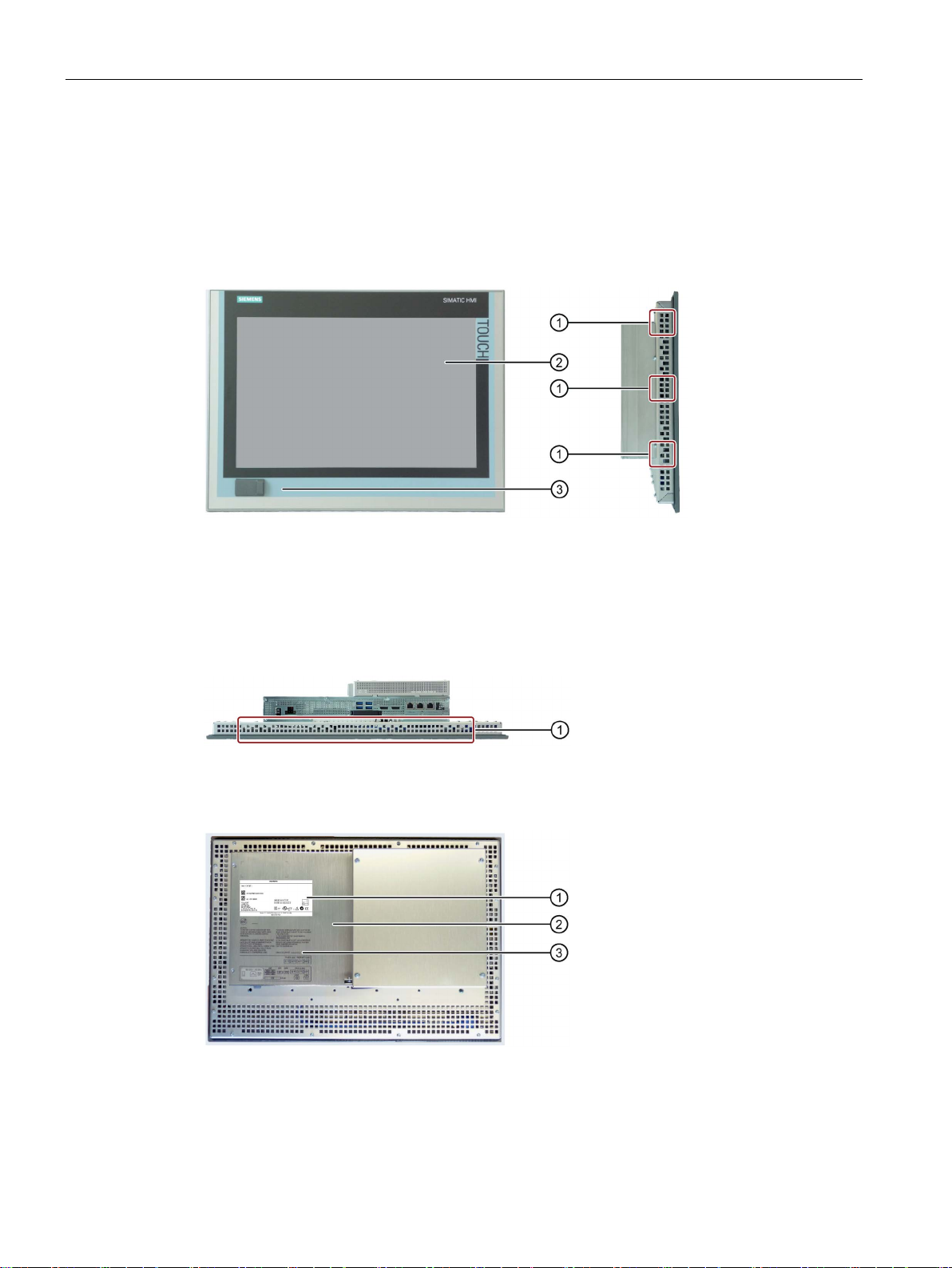
Devices with resistive single touch screen
Front and side views
①
Recesses, each of which for a mounting clip
②
Display with touch screen
③
USB socket
Bottom view
①
Recesses for one mounting clip each
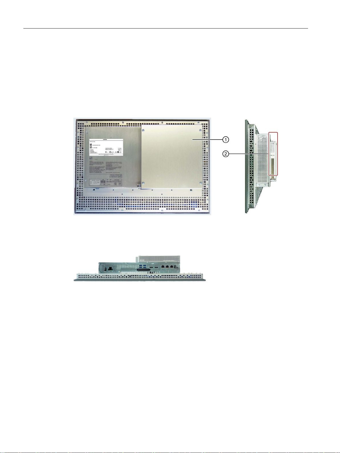
Rear view
①
Rating plate
②
Rear panel / rear panel of expansion
③
Labeling for the interface arrangement
1.2 Design of the built-in units
The bottom view shows a device with 24 V DC power supply.
SIMATIC IPC477E
12 Operating Instructions, 12/2016, A5E37455003-AB
Overview
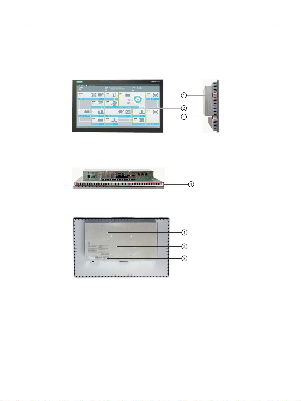
1.2.2
Devices with capacitive multi-touch screen
Front and side views
①
Recesses, each of which for a mounting clip
②
Display with touch screen
Bottom view
①
Recesses for one mounting clip each
Rear view
①
Rating plate
②
Rear panel
③
Labeling for the interfaces
1.2 Design of the built-in units
The following figures show the 19" device without PCIe card as an example.
SIMATIC IPC477E
Operating Instructions, 12/2016, A5E37455003-AB
13
Overview
1.2.3
Devices with expansions
1.2.3.1
Devices with PCIe card
Rear view and side view
①
Rear panel
②
PCIe card
Bottom view
1.2 Design of the built-in units
The following figures show the 15" device with resistive single-touch screen and a PCIe
expansion as an example.
SIMATIC IPC477E
14 Operating Instructions, 12/2016, A5E37455003-AB
Overview
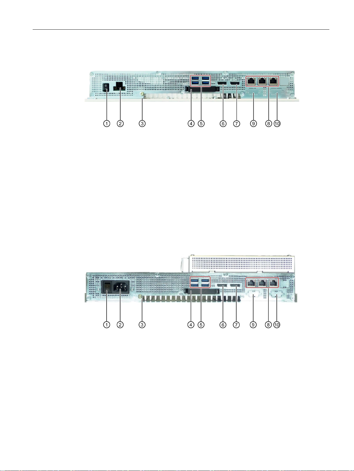
1.2.4
Interfaces and operator controls for devices with 24 V DC power supply
①
On/Off switch
②
24 V DC power supply
③ Protective conductor connection
④
Slot for external CFast card
With cover
⑤
4 x USB port
USB 3.0 high speed/high current
⑥
Display port
⑦
Display port
⑧
3 × Ethernet port
3 x RJ45 (10/100/1000 Mbps)
⑨
COM1 port (optional)
Serial interface, 9-pin D-Sub pin
⑩
COM2 port (optional)
Serial interface, 9-pin D-Sub pin
1.2.5
Interfaces and operator controls for devices with 100-240 V AC power supply
①
On/Off switch
②
100-240 V AC power supply
③
Protective conductor connection
④ Slot for external CFast card
With cover
⑤
4 x USB port
USB 3.0 high speed/high current
⑥
Display port
⑦ Display port
⑧
3 × Ethernet port
3 x RJ45 (10/100/1000 Mbps)
⑨
COM1 port (optional)
Serial interface, 9-pin D-Sub pin
⑩
COM2 port (optional)
Serial interface, 9-pin D-Sub pin
1.2 Design of the built-in units
SIMATIC IPC477E
Operating Instructions, 12/2016, A5E37455003-AB
15
Overview
1.3
Accessory kit
Built-in unit
1.4
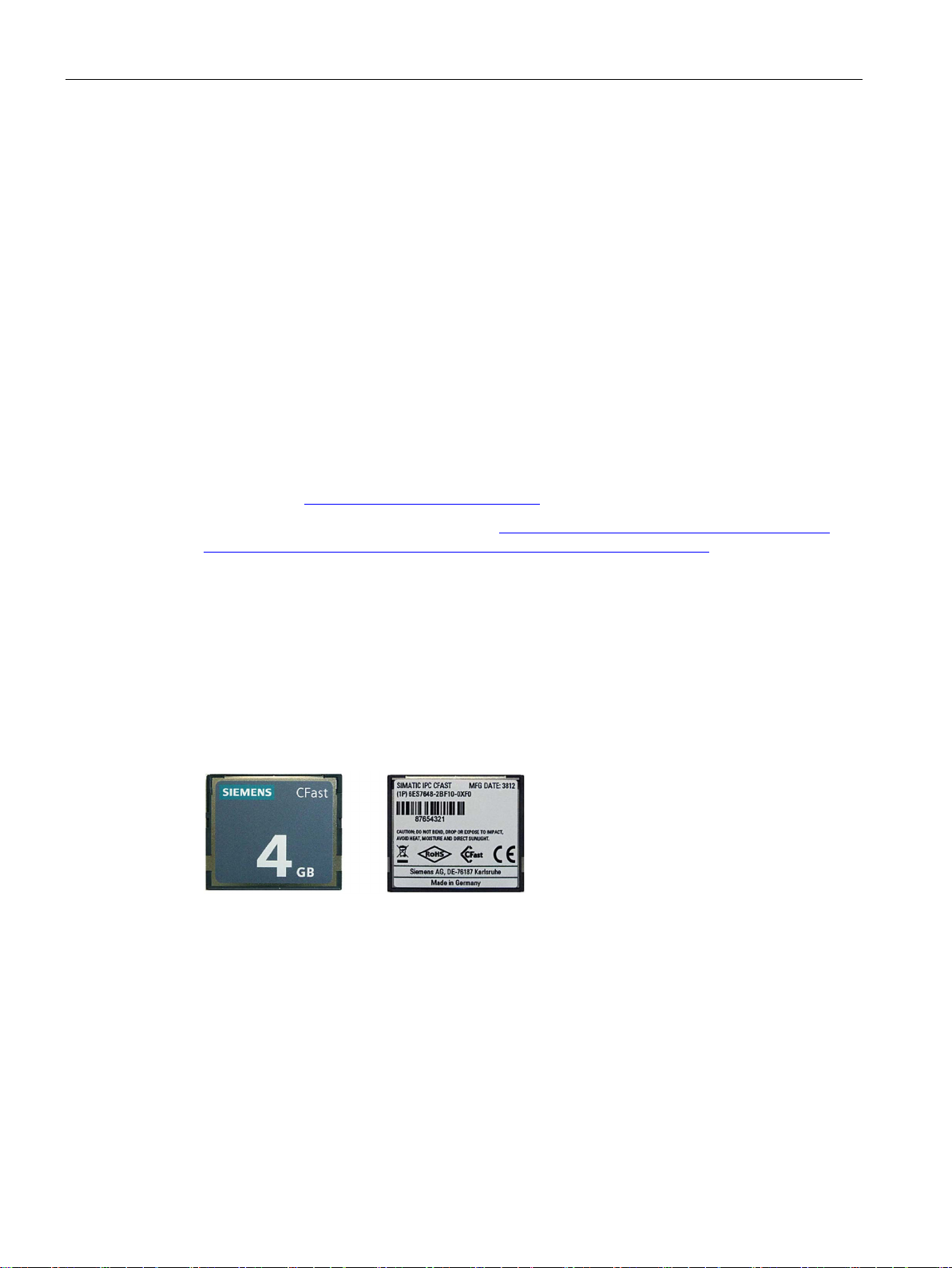
Accessories
SIMATIC IPC CFast cards
Memory modules
1.3 Accessory kit
The accessory kit contains:
● Connection terminal for connection of power supply
● Mounting clips for mounting the HMI device
Additional documents may be enclosed with the accessory kit.
Accessories are available for your device. These are not included in the product package.
You can find Information on available accessories on the Internet at:
Industry Mall (https://mall.industry.siemens.com)
Expansion components and accessories (http://www.automation.siemens.com/mcms/pc-
based-automation/en/industrial-pc/expansion_components_accessories)
● 2 GB optional or
● 4 GB optional or
● 8 GB optional or
● 16 GB optional or
● 30 GB optional
● SO-DIMM module 4096 MB DDR4-SDRAM
● SO-DIMM module 8192 MB DDR4-SDRAM
● SO-DIMM module 16384 MB DDR4-SDRAM
● SO-DIMM module 8192 MB DDR4-SDRAM ECC
● SO-DIMM module 16384 MB DDR4-SDRAM ECC
SIMATIC IPC477E
16 Operating Instructions, 12/2016, A5E37455003-AB
Overview
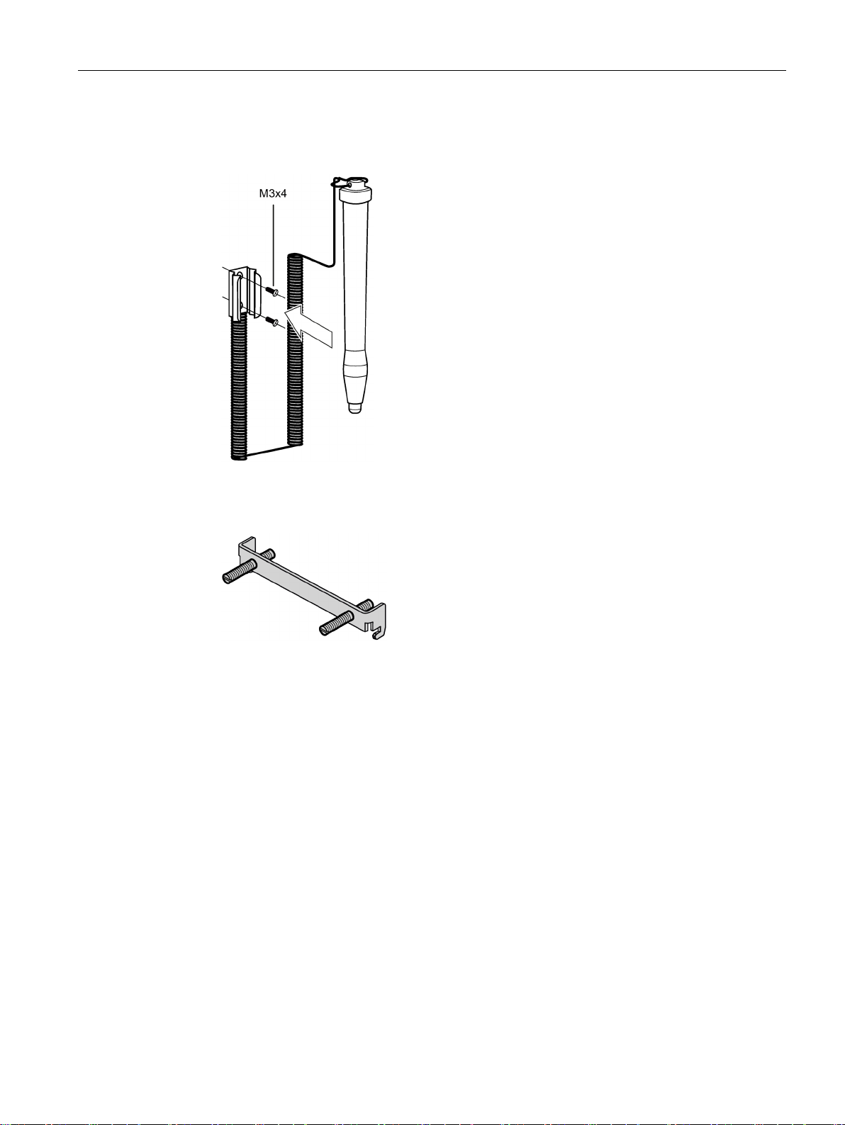
Other accessories
1.4 Accessories
● Touch stylus only for devices with resistive single-touch screen
● Mounting bracket
If there are higher requirements for the front seal, fasten the device with mounting
brackets in a control cabinet.
SIMATIC IPC477E
Operating Instructions, 12/2016, A5E37455003-AB
17

Overview
1.4 Accessories
SIMATIC IPC477E
18 Operating Instructions, 12/2016, A5E37455003-AB

2
2.1
General safety instructions
WARNING
Life-threatening voltages are present with an open control cabinet
System expansions
NOTICE
Damage through system expansions
NOTICE
"Open Type" UL508
When you install the device in a control cabinet, some areas or components in the open
control cabinet may be carrying life-threatening voltages.
If you touch these areas or components, you may be killed by electric shock.
Switch off the power supply to the cabinet before opening it.
Device and system expansions may be faulty and can affect the entire machine or plant.
The installation of expansions can damage the device, machine or plant. Device and
system expansions may violate safety rules and regulations regarding radio interference
suppression. If you install or exchange system expansions and damage your device, the
warranty becomes void.
Note the following for system expansions:
• Only install system expansion devices designed for this device. Contact your technical
support team or where you purchased your PC to find out which system expansion
devices may safely be installed.
• Read the information on electromagnetic compatibility (Page 113).
Note that the built-in unit is classified as "Open Type" for use in the area of Industrial
Control Equipment (UL508). The installation of the built-in unit in an enclosure conforming
to UL508 is a mandatory requirement for approval and operation in accordance with UL508.
SIMATIC IPC477E
Operating Instructions, 12/2016, A5E37455003-AB
19
Safety instructions
Battery and rechargeable battery
WARNING
Risk of explosion and release of harmful substances
Strong high-frequency radiation
NOTICE
Observe immunity to RF radiation
ESD Guideline
NOTICE
Electrostatic sensitive devices (ESD)
When you touch electrostatic sensitive components, you can destroy them through voltages
2.1 General safety instructions
Improper handling of lithium batteries can result in an explosion of the batteries.
Explosion of the batteries and the released pollutants can cause severe physical injury.
Worn batteries jeopardize the function of the device.
Note the following when handling lithium batteries:
• Replace spent batteries promptly. You can find information on installing and removing
the backup battery in the Operating Instructions.
• Replace the lithium battery only with an identical battery or types recommended by the
manufacturer.
• Do not throw lithium batteries into fire, do not solder on the cell body, do not recharge,
do not open, do not short-circuit, do not reverse polarity, do not heat above 100°C and
protect from direct sunlight, moisture and condensation.
The device has an increased immunity to RF radiation according to the specifications on
electromagnetic compatibility in the technical specifications.
Radiation exposure in excess of the specified immunity limits can impair device functions,
result in malfunctions and therefore injuries or damages.
Read the information on immunity to RF radiation in the technical specifications.
Electrostatic sensitive devices can be labeled with an appropriate symbol.
that are far below the human perception threshold.
If you work with components that can be destroyed by electrostatic discharge, observe the
ESD Guideline (Page 114).
SIMATIC IPC477E
20 Operating Instructions, 12/2016, A5E37455003-AB

Safety instructions
Industrial Security
Disclaimer for third-party software updates
Notes on protecting administrator accounts
2.1 General safety instructions
Siemens provides products and solutions with industrial security functions that support the
secure operation of plants, systems, machines and networks.
In order to protect plants, systems, machines and networks against cyber threats, it is
necessary to implement – and continuously maintain – a holistic, state-of-the-art industrial
security concept. Siemens’ products and solutions only form one element of such a concept.
Customer is responsible to prevent unauthorized access to its plants, systems, machines
and networks. Systems, machines and components should only be connected to the
enterprise network or the internet if and to the extent necessary and with appropriate security
measures (e.g. use of firewalls and network segmentation) in place.
Additionally, Siemens’ guidance on appropriate security measures should be taken into
account. For more information about industrial security, please visit
(http://www.siemens.com/industrialsecurity).
Siemens’ products and solutions undergo continuous development to make them more
secure. Siemens strongly recommends to apply product updates as soon as available and to
always use the latest product versions. Use of product versions that are no longer supported,
and failure to apply latest updates may increase customer’s exposure to cyber threats.
To stay informed about product updates, subscribe to the Siemens Industrial Security RSS
Feed under (https://support.industry.siemens.com).
This product includes third-party software. Siemens AG only provides a warranty for
updates/patches of the third-party software, if these have been distributed as part of a
Siemens software update service contract or officially released by Siemens AG. Otherwise,
updates/patches are undertaken at your own risk. You can find more information about our
Software Update Service offer on the Internet at Software Update Service
(http://www.automation.siemens.com/mcms/automation-software/en/software-update-
service).
A user with administrator privileges has extensive access and manipulation options in the
system.
Therefore, ensure there are adequate safeguards for protecting the administrator accounts
to prevent unauthorized changes. To do this, use secure passwords and a standard user
account for normal operation. Other measures, such as the use of security policies, should
be applied as needed.
SIMATIC IPC477E
Operating Instructions, 12/2016, A5E37455003-AB
21

Safety instructions
2.2
Notes on usage
WARNING
Risks associated with the unprotected machine or plant
Environment
NOTICE
Ambient conditions and chemical resistance
Unsuitable environmental conditions have a negative impact on device operation. Chemical
measures, such as a supply of clean air, the device may not be
ys use suitable cleaning agents. Read the information about Chemical resistance of
2.2 Notes on usage
According to the results of a risk analysis, certain hazard potentials associated with the
unprotected machine exist. These hazards could lead to personal injury.
Avoid such hazards by taking the following precautions in accordance with the risk analysis:
• Installation of additional safety equipment on the machine or plant. In particular, the
programming, parameter assignment and wiring of the inserted I/O modules must be
executed in accordance with the safety performance identified by the necessary risk
analysis (SIL, PL or Cat.).
• Use as intended must be validated for the device by means of a function test on the
plant. These tests help you to identify programming, parameter assignment and wiring
errors.
• Documentation of the test results that you can enter in the relevant safety verification
documents, if necessary.
substances such as cleaners or fuels may alter the color, shape and structure of the device
surface, for example, the front panel.
The device may be damaged. possibly resulting in malfunctions.
For this reason, please observe the following precautions:
• Always operate the device in closed rooms. All warranties shall be void in the case of
noncompliance.
• Operate the device only in accordance with the ambient conditions specified in the
technical specifications.
• Protect the device against dust, moisture and heat.
• Do not expose the device to direct sunlight or to other strong sources of light.
• Without additional safety
used in locations with harsh operating conditions caused by acidic vapors or gases.
• Observe the permitted mounting positions of the device.
• Do not obstruct the venting slots of the device.
• Alwa
the HMI devices and industrial PCs
(http://support.automation.siemens.com/WW/view/en/39718396) on the Internet.
SIMATIC IPC477E
22 Operating Instructions, 12/2016, A5E37455003-AB

Safety instructions
Note
Use in an industrial environment without additional protective measures
The device has been designed for use in a normal industrial environment in accordance with
IEC
2.2 Notes on usage
60721-3-3 (pollutant class 3C2 for chemical influences, 3S2 for dust without sand).
SIMATIC IPC477E
Operating Instructions, 12/2016, A5E37455003-AB
23

Safety instructions
2.2 Notes on usage
SIMATIC IPC477E
24 Operating Instructions, 12/2016, A5E37455003-AB

3
3.1
Preparing for mounting
3.1.1
Checking the delivery package
Procedure
Note
Damage to the device during transport and storage
If a
moisture may impact the unprotected unit. Damaged packaging indicates that ambient
conditions have already had a massive impact on the device and it may be damaged.
This ma
•
•
1. When accepting a delivery, please check the packaging for visible transport damage.
2. If any transport damage is present at the time of delivery, lodge a complaint at the
shipping company in charge. Have the shipper confirm the transport damage
immediately.
3. Unpack the device at its installation location.
4. Keep the original packaging in case you have to transport the unit again.
device is transported or stored without packaging, shocks, vibrations, pressure and
y cause the device, machine or plant to malfunction.
Keep the original packaging.
Pack the device in the original packaging for transportation and storage.
5. Check the contents of the packaging and any accessories you may have ordered for
completeness and damage.
SIMATIC IPC477E
Operating Instructions, 12/2016, A5E37455003-AB
25

Mounting and connecting the device
WARNING
Electric shock and fire hazard due to damaged device
NOTICE
Damage from condensation
3.1 Preparing for mounting
6. Please inform the delivery service immediately if the package contents are incomplete or
damaged or do not correspond with your order. Fax the enclosed form "SIMATIC IPC/PG
Quality Control Report".
A damaged device can be under hazardous voltage and trigger a fire in the machine or
plant. A damaged device has unpredictable properties and states.
Death or serious injury could occur.
Make sure that the damaged device is not inadvertently installed and put into operation.
Label the damaged device and keep it locked away. Send off the device for immediate
repair.
If the device is subjected to low temperatures or extreme fluctuations in temperature
during transportation, as is the case in cold weather, for example, moisture can build up
on or inside the device (condensation).
Moisture causes a short circuit in electrical circuits and damages the device.
In order to prevent damage to the device, proceed as follows:
• Store the device in a dry place.
• Bring the device to room temperature before starting it up.
• Do not expose the device to direct heat radiation from a heating device.
• If condensation develops, wait approximately 12 hours or until the device is
completely dry before switching it on.
7. Please keep the enclosed documentation in a safe place. It belongs to the device. You
need the documentation when you commission the device for the first time.
8. Write down the identification data of the device.
SIMATIC IPC477E
26 Operating Instructions, 12/2016, A5E37455003-AB
Mounting and connecting the device
3.1.2
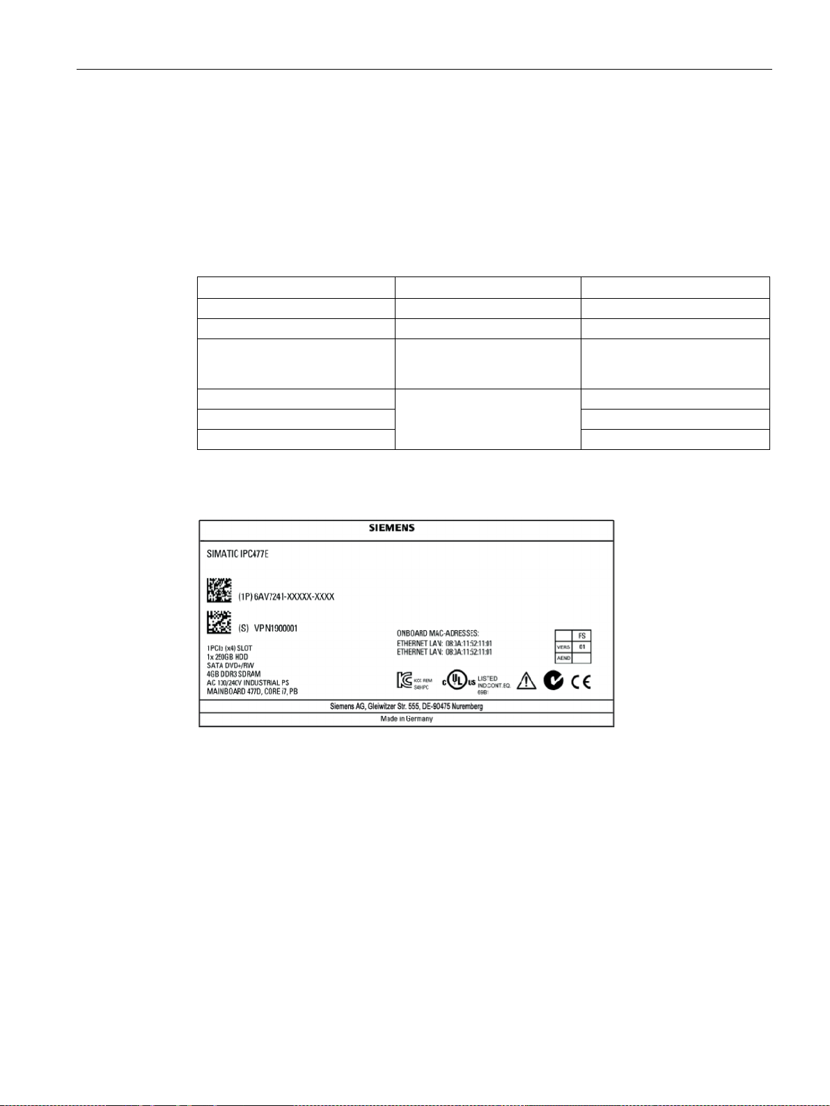
Device identification data
Unpacking the device
Identification date
Source
Value
Serial number
Rating plate
S VP ...
have the COA label
Ethernet address 1
Ethernet address 2
Ethernet address 3
Example of rating plate on SIMATIC IPC477E
3.1 Preparing for mounting
The device can be clearly identified with the help of this identification data in case of repairs
or theft.
Enter the identification data in the table below:
Article number of the device Rating plate 6AV7241 (SIMATIC IPC477E)
Microsoft Windows Product Key
Certificate of Authenticity (COA)
Back of the device Only devices with preinstalled
Windows operating systems
BIOS setup, "Advanced" menu
SIMATIC IPC477E
Operating Instructions, 12/2016, A5E37455003-AB
27

Mounting and connecting the device
COA label
3.1 Preparing for mounting
Microsoft Windows "Product Key" from the "Certificate of Authenticity" (COA):
The COA label is present only when Windows Embedded Standard 7 or Windows 7 is
installed.
● COA label of a device with the Windows Embedded Standard 7 operating system
● COA label of a device with Windows operating system
SIMATIC IPC477E
28 Operating Instructions, 12/2016, A5E37455003-AB
Mounting and connecting the device
3.1.3
Built-in unit
3.1.3.1
Permitted mounting positions
CAUTION
Danger from high temperature of the enclosure if built-in unit is touched
Note
Operation with hard disk
Operation with hard disk is only permitted in standard mounting position "Vertical installation
in horizontal format".
3.1 Preparing for mounting
The mounting positions described below are permitted for the built-in unit. For information on
the maximum permissible ambient temperatures during operation, refer to section
"Environmental conditions (Page 133)".
Self-heating can cause the temperature of the built-in unit to exceed 70 °C during operation
at an ambient temperature > 40 °C.
If you want to operate the built-in unit at an ambient temperature > 40 °C, you will have to
install it in a Restricted Access Location (RAL) such as a lockable control cabinet.
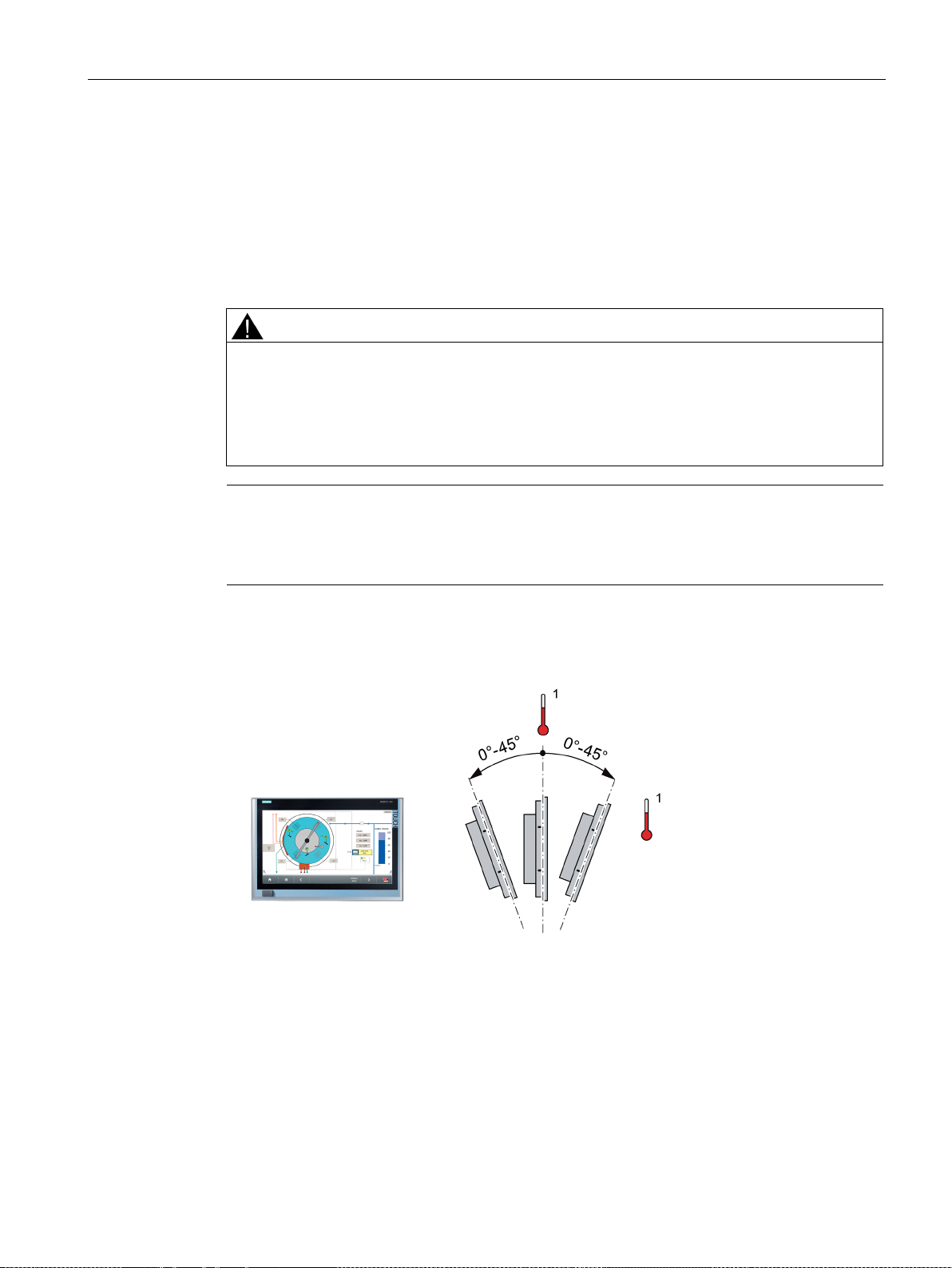
● Standard mounting position: Vertical installation in horizontal format
In this mounting position, the device enclosure satisfies the requirements of a fire
protection enclosure.
1
For temperature specifications, see section "Environmental conditions (Page 133)".
SIMATIC IPC477E
Operating Instructions, 12/2016, A5E37455003-AB
29
Mounting and connecting the device
CAUTION
Fire protection enclosure requirement not fulfilled
has to meet the requirement for a fire protection enclosure in the desired operating area.
3.1 Preparing for mounting
● Inclined installation in horizontal format with a vertical inclination of maximum ±45 °
In an inclined mounting position, the device enclosure satisfies the requirements of a fire
protection enclosure.
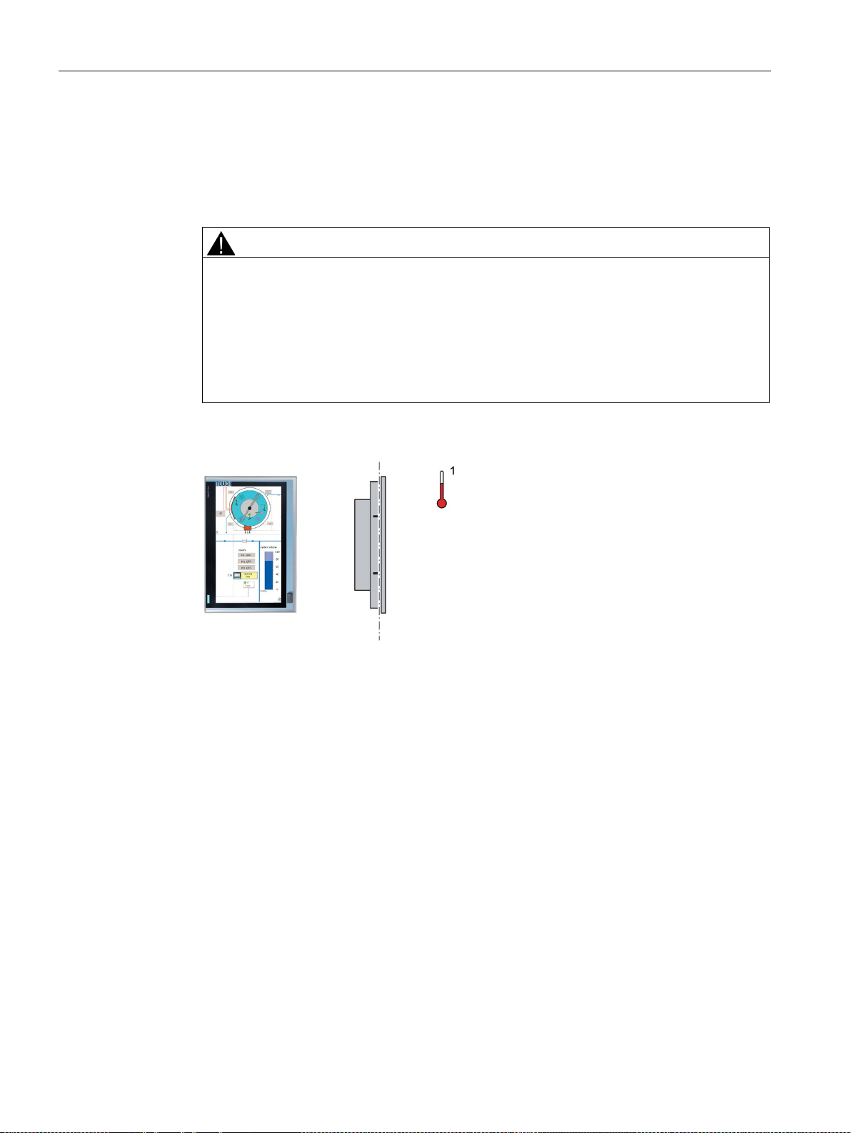
● Upright mounting in vertical format (only permitted for the built-in unit)
In the "Upright mounting in vertical position" mounting position, the device enclosure
does not satisfy the requirement of a fire protection enclosure.
If you want to operate the built-in unit in this mounting position, check if the built-in unit
If in doubt, install the built-in unit in an enclosure that is compliant with the requirements
of sections 4.6 and 4.7.3 of the IEC/UL/EN/DIN-EN 60950-1 standard.
Display rotated 90° vertical from the standard position. The power supply is located at the
top.
1
For temperature specifications, see section "Environmental conditions (Page 133)".
SIMATIC IPC477E
30 Operating Instructions, 12/2016, A5E37455003-AB
 Loading...