

Siemens SIMATIC IPC477D, SIMATIC IPC477D PRO Operating Instructions Manual

___________________
___________________
___________________
___________________
___________________
___________________
___________________
___________________
___________________
___________________
___________________
___________________
SIMATIC
Industrial PC
SIMATIC IPC477D, IPC477D PRO
Operating Instructions
11/2016
A5E31347228
Preface
Overview
1
Safety instructions
2
Mounting and connecting the
device
3
Commissioning the device
4
Operating the device and
device functions
5
Expanding the device and
assigning device parameters
6
Maintaining and servicing
your device
7
Technical information
8
Technical support
A
Markings and symbols
B
List of abbreviations
C
-AF

Siemens AG
Division Digital Factory
Postfach 48 48
90026 NÜRNBERG
GERMANY
A5E31347228-AF
Ⓟ
Copyright © Siemens AG 2016.
All rights reserved
Legal information
Warning notice system
DANGER
indicates that death or severe personal injury will result if proper precautions are not taken.
WARNING
indicates that death or severe personal injury may result if proper precautions are not taken.
CAUTION
indicates that minor personal injury can result if proper precautions are not taken.
NOTICE
indicates that property damage can result if proper precautions are not taken.
Qualified Personnel
personnel qualified
Proper use of Siemens products
WARNING
Siemens products may only be used for the applications described in the catalog and in the relevant technical
ambient conditions must be complied with. The information in the relevant documentation must be observed.
Trademarks
Disclaimer of Liability
This manual contains notices you have to observe in order to ensure your personal safety, as well as to prevent
damage to property. The notices referring to your personal safety are highlighted in the manual by a safety alert
symbol, notices referring only to property damage have no safety alert symbol. These notices shown below are
graded according to the degree of danger.
If more than one degree of danger is present, the warning notice representing the highest degree of danger will
be used. A notice warning of injury to persons with a safety alert symbol may also include a warning relating to
property damage.
The product/system described in this documentation may be operated only by
task in accordance with the relevant documentation, in particular its warning notices and safety instructions.
Qualified personnel are those who, based on their training and experience, are capable of identifying risks and
avoiding potential hazards when working with these products/systems.
Note the following:
for the specific
documentation. If products and components from other manufacturers are used, these must be recommended
or approved by Siemens. Proper transport, storage, installation, assembly, commissioning, operation and
maintenance are required to ensure that the products operate safely and without any problems. The permissible
All names identified by ® are registered trademarks of Siemens AG. The remaining trademarks in this publication
may be trademarks whose use by third parties for their own purposes could violate the rights of the owner.
We have reviewed the contents of this publication to ensure consistency with the hardware and software
described. Since variance cannot be precluded entirely, we cannot guarantee full consistency. However, the
information in this publication is reviewed regularly and any necessary corrections are included in subsequent
editions.
10/2016 Subject to change

Preface
Purpose of the Operating Instructions
Basic knowledge required
Scope of the operating instructions
Scope of this documentation
These operating instructions contain all the information you need for the commissioning and
operation of the SIMATIC IPC477D.
It is intended both for programming and testing personnel who commission the device and
connect it with other units (automation systems, programming devices), as well as for service
and maintenance personnel who install add-ons or carry out fault/error analyses.
A solid background in personal computers and Microsoft operating systems is required to
understand this manual. General knowledge in the field automation control engineering is
recommended.
These operating instructions apply to "SIMATIC IPC477D" industrial PCs with article
numbers 6AV724..... (built-in unit) and 6AV725... (PRO device)
The documentation for the IPC includes the following:
● Product information, e.g. "Important notes on your device"
● Quick Install Guide SIMATIC IPC477D
● Quick Install Guide SIMATIC IPC477D PRO
● Operating Instructions SIMATIC IPC477D, IPC477D PRO
The PDF version of the documentation is supplied with the device on the
"Documentation and Drivers" CD/DVD.
SIMATIC IPC477D, IPC477D PRO
Operating Instructions, 11/2016, A5E31347228-AF
3

Preface
Conventions
Note
A note is important information about the product, handling the product or a
specific sections of the documentation that require special consideration.
History
Edition
Comments
01/2013
First edition
07/2013
Amendments and corrections
06/2014
Description of devices with capacitive multi-touch screen
11/2014
Update with IPC Wizard 2.1 and corrections
(flange on bottom)
11/2016
Amendment to the Extension Unit
1.) Available as of 11/2016
In these operating instructions, "device" is used as the standard term for
"SIMATIC IPC477D" (built-in unit) or "SIMATIC IPC477D PRO" (PRO device). "CP" is used
as an abbreviation for "CP 1616 onboard" (for PROFINET) or "CP 5622" (for PROFIBUS).
In these operating instructions, the terms "Windows Embedded Standard 7 P" and
"Windows Embedded Standard 7 E" are also abbreviated with the term "Windows
Embedded Standard". "Windows 7" is used as an abbreviation for "Windows 7 Ultimate".
A touch device generally refers to a device with a capacitive multi-touch screen or a resistive
single touch screen. Touch screen is the general term for a resistive single touch screen or a
capacitive multi-touch screen.
reference to
The following editions of these operating instructions have already been published:
07/2015 Description of the 19" PRO devices: fully enclosed, mounting prepared for support arm
without extension elements (flange on top)/prepared for stand/extension elements
08/2016
• Description of the 15"
for support arm without extension elements (flange on top)/prepared for
stand/extension elements (flange on bottom)/prepared for support arm and extension elements
• Description of the built-in units with ATEX/IECEx/UL Hazloc approval.
• Description of the built-in units with marine approval.
1.)
and 22" PRO devices: fully enclosed, mounting prepared
SIMATIC IPC477D, IPC477D PRO
4 Operating Instructions, 11/2016, A5E31347228-AF

Table of contents
Preface ...................................................................................................................................................... 3
1 Overview .................................................................................................................................................. 11
2 Safety instructions ................................................................................................................................... 41
3 Mounting and connecting the device........................................................................................................ 47
1.1 Product description ................................................................................................................. 11
1.2 Design of the built-in units ...................................................................................................... 15
1.2.1 Devices with resistive single touch screen ............................................................................. 15
1.2.2 Devices with capacitive multi-touch screen ............................................................................ 17
1.2.3 Touch/Key devices with resistive single touch screen ............................................................ 18
1.2.4 Devices with expansions ........................................................................................................ 20
1.2.4.1 Devices with DVD drive .......................................................................................................... 20
1.2.4.2 Devices with PCIe card ........................................................................................................... 21
1.2.4.3 Devices with PCIe card and with DVD drive ........................................................................... 22
1.2.5 Operator controls or touch/key devices with resistive single-touch screen ............................ 23
1.2.6 Interfaces and operator controls for devices with 24 V DC power supply .............................. 24
1.2.7 Interfaces and operator controls for devices with 240 V AC power supply ............................ 26
1.3 Design of the PRO device ...................................................................................................... 28
1.3.1 Interfaces and operator controls for PRO device ................................................................... 31
1.4 Accessory kit ........................................................................................................................... 32
1.5 Accessories ............................................................................................................................. 32
1.6 System components for built-in units ...................................................................................... 34
1.7 System components for PRO devices .................................................................................... 35
1.7.1 Base adapter ........................................................................................................................... 35
1.7.2 Adapter set for support arm and stand mounting of PRO device ........................................... 36
1.7.3 Round tube adapter ................................................................................................................ 37
1.7.4 Extension Unit and operator controls ...................................................................................... 39
2.1 General safety instructions ..................................................................................................... 41
2.2 Notes on usage ....................................................................................................................... 44
3.1 Preparing for mounting ........................................................................................................... 47
3.1.1 Checking the delivery package ............................................................................................... 47
3.1.2 Device identification data ........................................................................................................ 49
3.1.3 Built-in unit .............................................................................................................................. 51
3.1.3.1 Permitted mounting positions ................................................................................................. 51
3.1.3.2 Preparing the mounting cutout ................................................................................................ 53
3.1.3.3 Labeling the function keys ...................................................................................................... 55
3.1.4 PRO device ............................................................................................................................. 57
3.1.4.1 Permitted mounting positions ................................................................................................. 57
SIMATIC IPC477D, IPC477D PRO
Operating Instructions, 11/2016, A5E31347228-AF
5

Table of contents
4 Commissioning the device ..................................................................................................................... 103
3.2 Installing the built-in unit ........................................................................................................ 59
3.2.1 Installation guidelines ............................................................................................................. 59
3.2.2 Mounting clips or mounting brackets, position for IP65-compliant installation ...................... 61
3.2.3 Mounting the device with mounting clips ............................................................................... 63
3.2.4 Mounting the device with mounting brackets ......................................................................... 65
3.2.5 Position of the mounting clips for IP66-complaint installation ................................................ 67
3.3 Mounting the PRO device ...................................................................................................... 68
3.3.1 Notes on mounting ................................................................................................................. 68
3.3.2 Prepared for support arm or stand without extension elements (flange on top) .................... 70
3.3.3 Prepared for support arm and extension elements (flange mount) ....................................... 74
3.4 Connecting the device ........................................................................................................... 78
3.4.1 Notes on connecting .............................................................................................................. 78
3.4.2 Power supply built-in unit ....................................................................................................... 80
3.4.2.1 Connecting the protective earth ............................................................................................. 80
3.4.2.2 Connect 100-240 VAC power supply ..................................................................................... 82
3.4.2.3 Connecting the terminal ......................................................................................................... 85
3.4.2.4 Connecting the 24 V DC power supply .................................................................................. 86
3.4.3 Power supply PRO device ..................................................................................................... 88
3.4.3.1 Opening and closing the terminal compartment cover .......................................................... 88
3.4.3.2 connecting the PE conductor ................................................................................................. 91
3.4.3.3 Connecting the 24 VDC power supply ................................................................................... 92
3.4.4 Connecting peripheral equipment .......................................................................................... 94
3.4.5 Connecting the device to networks ........................................................................................ 95
3.4.6 PROFINET ............................................................................................................................. 97
3.4.7 Securing cables on the built-in unit ........................................................................................ 99
3.4.7.1 Attaching PROFINET strain relief ........................................................................................ 100
3.4.7.2 Securing cables in the built-in unit with ATEX/IECEx/UL Hazloc approval ......................... 101
3.4.8 Securing the cables on the PRO device .............................................................................. 102
4.1 General information on commissioning ............................................................................... 103
4.2 Initial commissioning ............................................................................................................ 105
4.3 Windows Action Center ........................................................................................................ 107
4.4 Notes on various device configurations ............................................................................... 108
4.4.1 SIMATIC IPC Wizard 2.1 ..................................................................................................... 108
4.4.1.1 System requirements ........................................................................................................... 108
4.4.1.2 Installing IPC Wizard ............................................................................................................ 110
4.4.2 Notes on the DVD burner ..................................................................................................... 112
SIMATIC IPC477D, IPC477D PRO
6 Operating Instructions, 11/2016, A5E31347228-AF

Table of contents
5 Operating the device and device functions ............................................................................................ 113
6 Expanding the device and assigning device parameters ....................................................................... 133
7 Maintaining and servicing your device ................................................................................................... 149
5.1 Operator input options .......................................................................................................... 113
5.2 Operating a device with resistive single touch screen .......................................................... 114
5.3 Operating a capacitive multi-touch screen device and PRO device ..................................... 115
5.4 Operating a touch/key device ............................................................................................... 118
5.5 IPC Wizard functions ............................................................................................................ 121
5.6 Extended device functions .................................................................................................... 122
5.6.1 Monitoring functions .............................................................................................................. 122
5.6.1.1 Overview of the monitoring functions .................................................................................... 122
5.6.1.2 Temperature monitoring/display ........................................................................................... 123
5.6.1.3 Watchdog (WD) .................................................................................................................... 124
5.6.1.4 Battery monitoring ................................................................................................................. 125
5.6.2 Enhanced Write Filter ........................................................................................................... 125
5.6.3 File Based Write Filter (FBWF) ............................................................................................. 128
5.6.4 Buffer memory NVRAM ........................................................................................................ 129
5.6.5 Active Management Technology (AMT) ............................................................................... 130
5.6.6 Trusted Platform Modul (TPM) ............................................................................................. 132
6.1 Opening the device ............................................................................................................... 133
6.1.1 Opening the built-in unit ........................................................................................................ 133
6.1.2 Opening and closing the backplane cover PRO device ....................................................... 135
6.2 Installing and removing a memory module ........................................................................... 138
6.3 Removing a PCIe card (built-in units with PCIe card without DVD drive) ............................ 140
6.4 Removing a PCIe card (built-in units with PCIe card and DVD drive) .................................. 142
6.5 Installing and removing a DVD drive (built-in unit only) ........................................................ 142
6.6 Installing and removing a CFast card ................................................................................... 144
6.6.1 Installing and removing a CFast card (external slot) ............................................................ 144
6.6.2 Installing and removing a CFast card (internal slot) ............................................................. 146
7.1 Maintenance ......................................................................................................................... 149
7.2 Repair information ................................................................................................................. 150
7.3 Cleaning the Device Front .................................................................................................... 153
7.4 Installing and removing hardware ......................................................................................... 154
7.4.1 Built-in unit ............................................................................................................................ 154
7.4.1.1 Replacing back-up battery (device with 12" display) ............................................................ 154
7.4.1.2 Replacing back-up battery (devices with 15", 19" or 22" display) ........................................ 155
7.4.1.3 Replacing SSD (device with 12" display) .............................................................................. 156
7.4.1.4 Replacing the SSD (devices with 15", 19" or 22" display) .................................................... 158
7.4.1.5 Replacing HDD ..................................................................................................................... 160
7.4.2 PRO device ........................................................................................................................... 161
7.4.2.1 Replacing the backup battery (PRO device) ........................................................................ 161
7.4.2.2 Replacing the SSD (PRO device) ......................................................................................... 162
SIMATIC IPC477D, IPC477D PRO
Operating Instructions, 11/2016, A5E31347228-AF
7

Table of contents
8 Technical information ............................................................................................................................. 179
7.5 Installing the software .......................................................................................................... 164
7.5.1 Reinstalling the operating system ........................................................................................ 164
7.5.1.1 General installation procedure ............................................................................................. 164
7.5.1.2 Restoring the factory state of the software using the Restore DVD .................................... 165
7.5.1.3 Windows 7 ............................................................................................................................ 167
7.5.1.4 Windows Embedded Standard ............................................................................................ 171
7.5.2 Partitioning data media ........................................................................................................ 173
7.5.2.1 Partitioning in Windows Embedded Standard 7 .................................................................. 173
7.5.2.2 Partitioning in Windows 7 Ultimate ...................................................................................... 174
7.5.2.3 Adapting partitions in Windows 7 Ultimate and Windows Embedded Standard 7 .............. 174
7.5.3 Installing drivers and software ............................................................................................. 176
7.5.4 Update installation ............................................................................................................... 177
7.5.4.1 Updating the operating system ............................................................................................ 177
7.5.4.2 Installing or updating application programs and drivers ...................................................... 177
7.5.4.3 CP 1616 onboard ................................................................................................................. 177
7.5.5 Backing up data ................................................................................................................... 178
7.6 Recycling and disposal ........................................................................................................ 178
8.1 Certificates and approvals ................................................................................................... 179
8.2 Directives and declarations .................................................................................................. 184
8.2.1 Electromagnetic compatibility .............................................................................................. 184
8.2.2 ESD guideline ...................................................................................................................... 185
8.3 Dimension drawings ............................................................................................................. 188
8.3.1 Dimension drawing of 15" device with capacitive multi-touch screen ................................. 188
8.3.2 Dimension drawing of 19" device with capacitive multi-touch screen ................................. 190
8.3.3 Dimension drawing of 22" device with capacitive multi-touch screen ................................. 191
8.3.4 Dimension drawing 15" PRO device with capacitive multi-touch screen ............................. 192
8.3.5 Dimension drawing 19" PRO device with capacitive multi-touch screen ............................. 196
8.3.6 Dimension drawing 22" PRO device with capacitive multi-touch screen ............................. 199
8.3.7 Dimension drawing of 12" device with resistive single-touch screen .................................. 202
8.3.8 Dimension drawing of 15" device with resistive single-touch screen .................................. 203
8.3.9 Dimension drawing of 19" device with resistive single-touch screen .................................. 204
8.3.10 Dimension drawing of 22" device with resistive single-touch screen .................................. 205
8.3.11 Dimension drawing of 15" touch/key device with resistive single-touch screen .................. 206
8.3.12 Dimension drawing of labeling strips ................................................................................... 207
8.4 Technical specifications ....................................................................................................... 208
8.4.1 Built-in unit ........................................................................................................................... 208
8.4.1.1 General technical specifications .......................................................................................... 208
8.4.1.2 Environmental conditions ..................................................................................................... 213
8.4.2 PRO device .......................................................................................................................... 217
8.4.2.1 General specifications PRO device ..................................................................................... 217
8.4.2.2 Ambient conditions PRO device .......................................................................................... 222
8.4.2.3 Information on insulation tests, protection class and degree of protection .......................... 223
8.4.2.4 Rated voltages ..................................................................................................................... 223
8.4.3 Power requirements of the components .............................................................................. 224
8.4.4 Integrated DC power supply ................................................................................................ 224
8.4.5 Alternating voltage supply PRO device (AC) ....................................................................... 225
SIMATIC IPC477D, IPC477D PRO
8 Operating Instructions, 11/2016, A5E31347228-AF

Table of contents
8.5 Hardware descriptions .......................................................................................................... 226
8.5.1 External ports ........................................................................................................................ 226
8.5.1.1 COM1/COM2 ........................................................................................................................ 226
8.5.1.2 CFast .................................................................................................................................... 227
8.5.1.3 DisplayPort ............................................................................................................................ 228
8.5.1.4 DVI-I ...................................................................................................................................... 229
8.5.1.5 Ethernet ................................................................................................................................ 230
8.5.1.6 USB 3.0 port ......................................................................................................................... 230
8.5.1.7 USB 2.0 ................................................................................................................................. 231
8.5.1.8 PROFIBUS ............................................................................................................................ 231
8.5.1.9 PROFINET ............................................................................................................................ 232
8.5.2 Internal ports ......................................................................................................................... 233
8.5.2.1 PCIe card .............................................................................................................................. 233
8.5.3 System resources ................................................................................................................. 235
8.5.3.1 Currently allocated system resources ................................................................................... 235
8.5.3.2 Assignment of system resources .......................................................................................... 235
8.5.4 I/O Address Areas ................................................................................................................. 237
8.5.4.1 Overview of the internal module registers ............................................................................ 237
8.5.4.2 Watchdog trigger register (read only, address 066h) ........................................................... 237
8.5.4.3 Watchdog enable register / 066h select register (read/write, address 062h) ....................... 237
8.5.4.4 Battery status register (read-only, address 50Ch) ................................................................ 239
8.5.4.5 NVRAM address register ...................................................................................................... 239
8.5.5 CP 1616 onboard communications processor ...................................................................... 240
8.5.5.1 Introduction ........................................................................................................................... 240
8.5.5.2 Firmware Loader ................................................................................................................... 242
8.5.5.3 Further actions in STEP 7/NCM PC ..................................................................................... 244
8.6 BIOS description ................................................................................................................... 245
8.6.1 Overview ............................................................................................................................... 245
8.6.2 Opening the BIOS selection menu ....................................................................................... 246
8.6.3 Structure of the BIOS Setup menu ....................................................................................... 248
8.6.4 Exit menu .............................................................................................................................. 250
8.6.5 BIOS Setup settings.............................................................................................................. 251
8.6.6 BIOS update ......................................................................................................................... 254
8.6.7 Alarm, error and system messages ...................................................................................... 256
8.7 Active Management Technology (AMT) ............................................................................... 257
8.7.1 Introduction ................................................................................................
........................... 257
8.7.2 Overview of AMT .................................................................................................................. 258
8.7.3 Enabling Intel® AMT / basic configuration ............................................................................ 258
8.7.4 Resetting the Intel® AMT to the default settings and disabling AMT ................................... 260
8.7.5 Determining the network address ......................................................................................... 260
8.7.6 Forcing user consent ............................................................................................................ 261
8.8 Functional scope in Windows ............................................................................................... 262
8.8.1 Windows Embedded Standard 7 .......................................................................................... 262
SIMATIC IPC477D, IPC477D PRO
Operating Instructions, 11/2016, A5E31347228-AF
9

Table of contents
A Technical support .................................................................................................................................. 265
B Markings and symbols ........................................................................................................................... 269
C List of abbreviations ............................................................................................................................... 273
Glossary ................................................................................................................................................ 279
Index ...................................................................................................................................................... 287
A.1 Service and support ............................................................................................................. 265
A.2 Problem solving .................................................................................................................... 266
A.3 Notes on the use of third-party modules .............................................................................. 268
B.1 Overview .............................................................................................................................. 269
B.2 Safety ................................................................................................................................... 269
B.3 Operator controls ................................................................................................................. 269
B.4 Certificates, approvals and markings ................................................................................... 270
B.5 Interfaces ............................................................................................................................. 271
SIMATIC IPC477D, IPC477D PRO
10 Operating Instructions, 11/2016, A5E31347228-AF
1
1.1
Product description
Features
The SIMATIC IPC477D provides high-level industrial functionality.
● Compact design
● Maintenance-free operation
● Rugged
● Ex approval
● Used for shipping and offshore applications
In addition to the established display sizes, the range has been extended by the PRO device
with all-round IP65 degree of protection; the device not only impresses with its ease of
servicing, but also with its sophisticated design and low mounting depth.
SIMATIC IPC477D, IPC477D PRO
Operating Instructions, 11/2016, A5E31347228-AF
11

Overview
Device variants
Built-in units with capacitive multi-touch screen
PRO device with capacitive multi-touch screen
1.1 Product description
The delivery note contains information on the precise scope of functions and product
package for your device.
The SIMATIC IPC477D is available in the following device variants, which differ in regard to
the display size, operating method and optional expansions:
● Display:
– 15.6" display, resolution: 1366 x 768 pixels
– 19" display, resolution: 1366 x 768 pixels
– 22" display, resolution: 1920 x 1080 pixels
● with DVD drive
● with PCIe slot
● with DVD drive and PCIe slot
● Display:
– 15'' display, resolution: 1366 x 768 pixels (available as of 11/2016)
– 19" display, resolution: 1366 x 768 pixels
– 22" display, resolution: 1920 x 1080 pixels
● optionally prepared for:
– Support arm without extension elements (flange on top)
– Support arm and extension elements (round tube)
– Stand/extension elements (flange on bottom)
● A base adapter and adapter sets that can be ordered separately support mounting
systems from various manufacturers.
– Base adapter for support arm and stand included in the scope of delivery.
– Cover plate for device version for support arm and extension elements included in the
scope of delivery.
● Fully dust-proof and splash-proof with IP65 degree of protection and Enclosure Type
4X / 12 (indoor use only)
● With SSD and CFast card
SIMATIC IPC477D, IPC477D PRO
12 Operating Instructions, 11/2016, A5E31347228-AF

Overview
Note
No PROFIBUS for 15" PRO device
Devices with resistive single touch screen
Touch/Key devices with resistive single touch screen
1.1 Product description
The following options are not available for PRO devices:
● Hard disk drive
● DVD drive
● PCIe expansion
● 2nd COM interface
● 240 V AC power supply
● Display:
– 12'' display, resolution: 1280 x 800 pixels
– 15" display, resolution: 1280 x 800 pixels
– 19" display, resolution: 1366 x 768 pixels
– 22" display, resolution: 1920 x 1080 pixels
● with DVD drive (not for device with 12" display)
● with PCIe slot (not for device with 12" display)
● with DVD drive and PCIe slot (not for device with 12" display)
● Display:
– 15" display, resolution: 1280 x 800 pixels
● with DVD drive
● with PCIe slot
● with DVD drive and PCIe slot
● Membrane keyboard with alphanumeric keys, numeric keys, cursor keys, control keys,
function keys, and softkeys
SIMATIC IPC477D, IPC477D PRO
Operating Instructions, 11/2016, A5E31347228-AF
13

Overview
Operating systems
Display
Operating system
Windows 7 Ultimate
(32/64-bit)
Windows Embedded
Standard 7 P (32-bit)
Windows Embedded
Standard 7 E (32/64-bit)
screen
Touch/key devices x
x
*
WES7E.
1.1 Product description
The following table shows which operating systems are available for which devices:
Devices with resistive single touch
screen
Devices with capacitive multi-touch
WES7E is available in addition only for the IPC477D Pro devices. Multitouch is operated in single touch mode with
x x
x x x*
SIMATIC IPC477D, IPC477D PRO
14 Operating Instructions, 11/2016, A5E31347228-AF

Overview
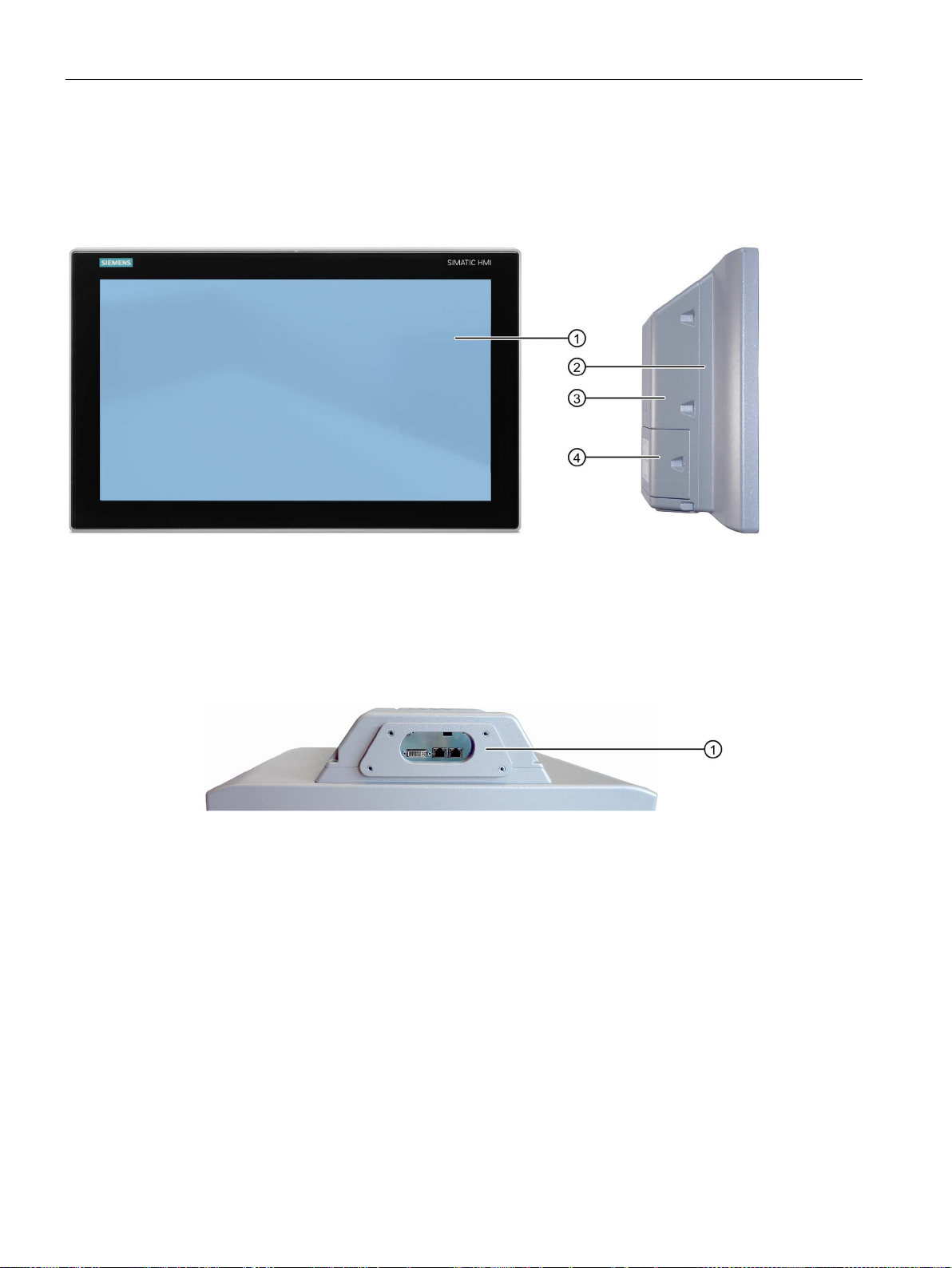
1.2
Design of the built-in units
1.2.1
Devices with resistive single touch screen
Front and side views
①
Recesses, each of which for a mounting clip
②
Display with touch screen
Bottom view
①
Recesses, each for a mounting clip
1.2 Design of the built-in units
The following figures show the 12" device as an example.
The bottom view shows a device with 24 V DC power supply and PROFIBUS interface.
SIMATIC IPC477D, IPC477D PRO
Operating Instructions, 11/2016, A5E31347228-AF
15
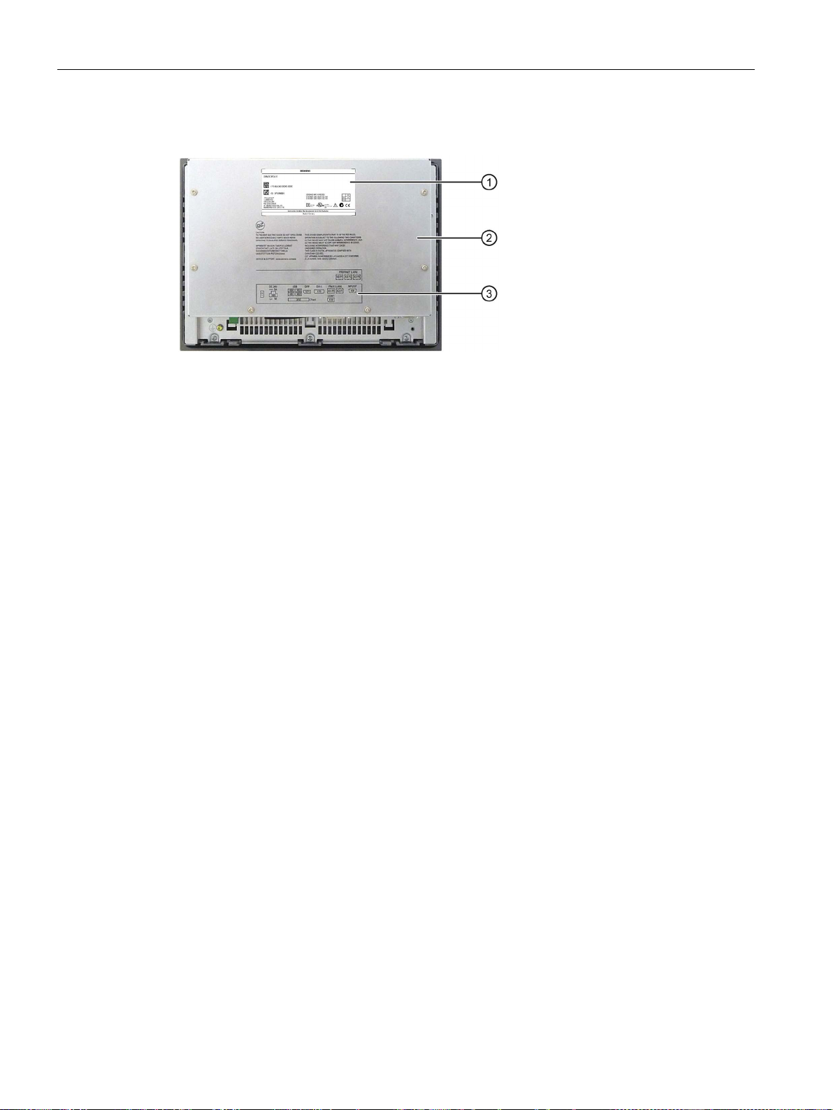
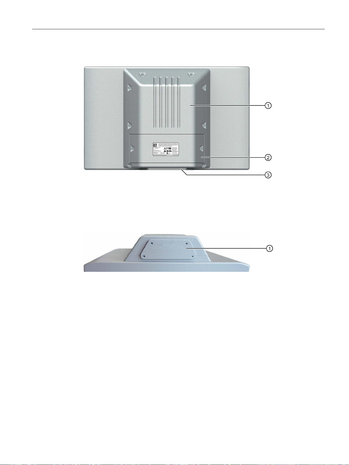
Overview
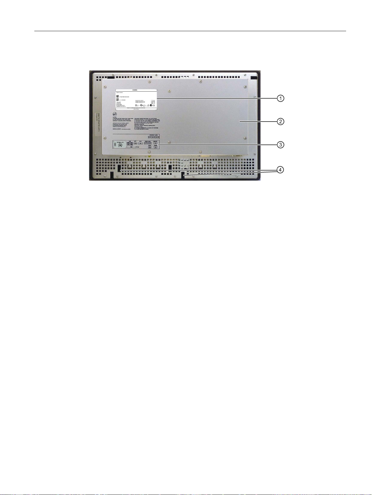
Rear view
①
Rating plate
②
Rear panel
③
Labeling for the interface arrangement
1.2 Design of the built-in units
SIMATIC IPC477D, IPC477D PRO
16 Operating Instructions, 11/2016, A5E31347228-AF
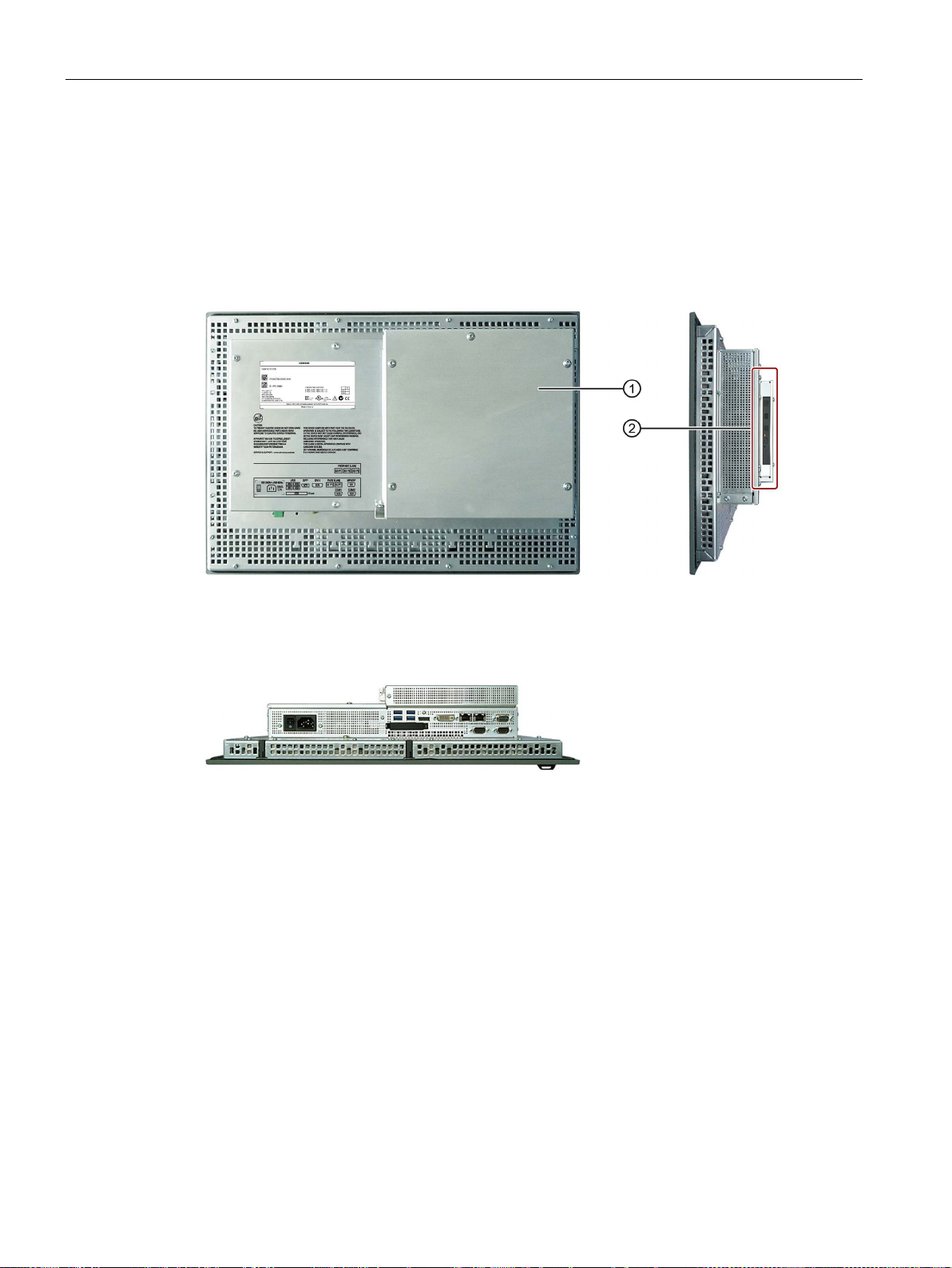
Overview
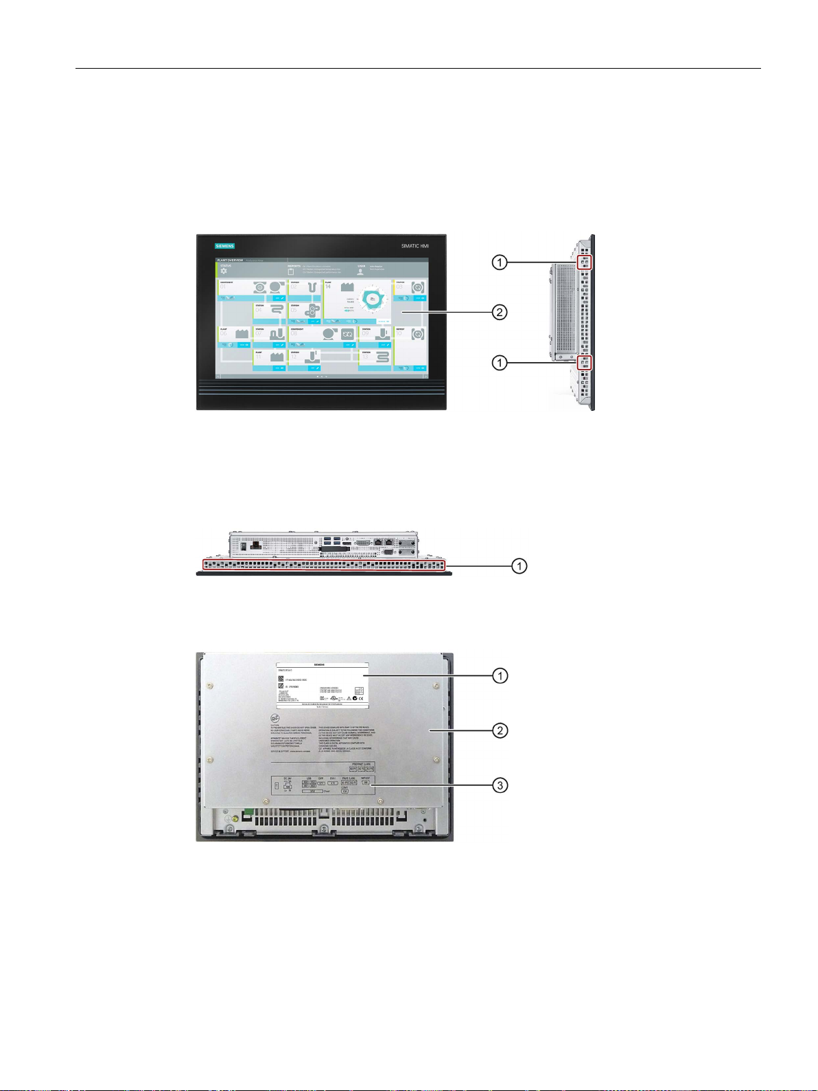
1.2.2
Devices with capacitive multi-touch screen
Front and side views
①
Recesses, each of which for a mounting clip
②
Display with touch screen
Bottom view
①
Recesses, each for a mounting clip
Rear view
①
Rating plate
②
Rear panel
③
Labeling for the interfaces
1.2 Design of the built-in units
The following figures show the 19" device without DVD drive and without PCIe card as an
example.
The bottom view shows a device with 24 VDC power supply without fieldbus interface.
SIMATIC IPC477D, IPC477D PRO
Operating Instructions, 11/2016, A5E31347228-AF
17
Overview
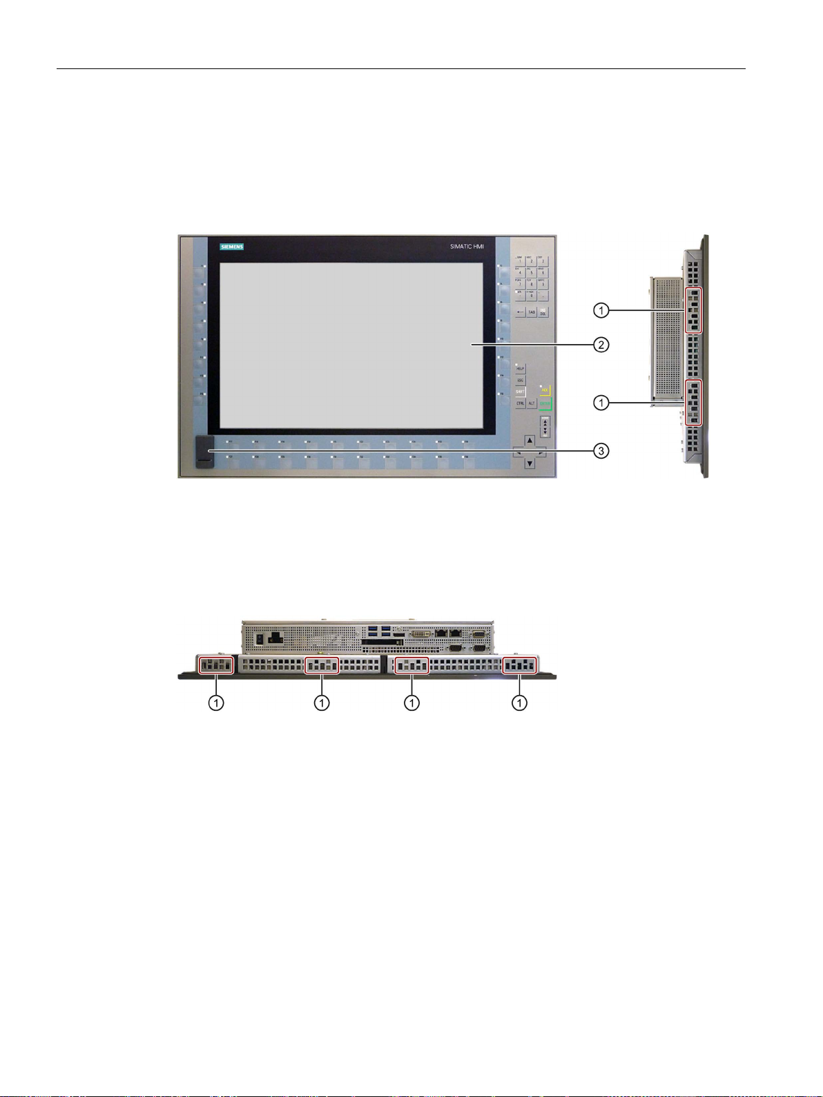
1.2.3
Touch/Key devices with resistive single touch screen
Front and side views
①
Recesses, each of which for a mounting clip
②
Display with touch screen
③
USB port
Bottom view
①
Recesses, each of which for a mounting clip
1.2 Design of the built-in units
The following figures show the Touch/Key device (15" only) without DVD drive and without
PCIe card as an example.
The bottom view shows a device with 24 V DC power supply and PROFIBUS interface.
SIMATIC IPC477D, IPC477D PRO
18 Operating Instructions, 11/2016, A5E31347228-AF
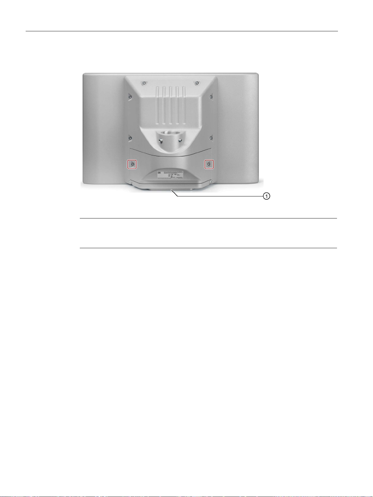
Overview
Rear view
①
Rating plate
②
Rear panel
③
Labeling for the interface arrangement
④
Guides for labeling strips
1.2 Design of the built-in units
SIMATIC IPC477D, IPC477D PRO
Operating Instructions, 11/2016, A5E31347228-AF
19
Overview
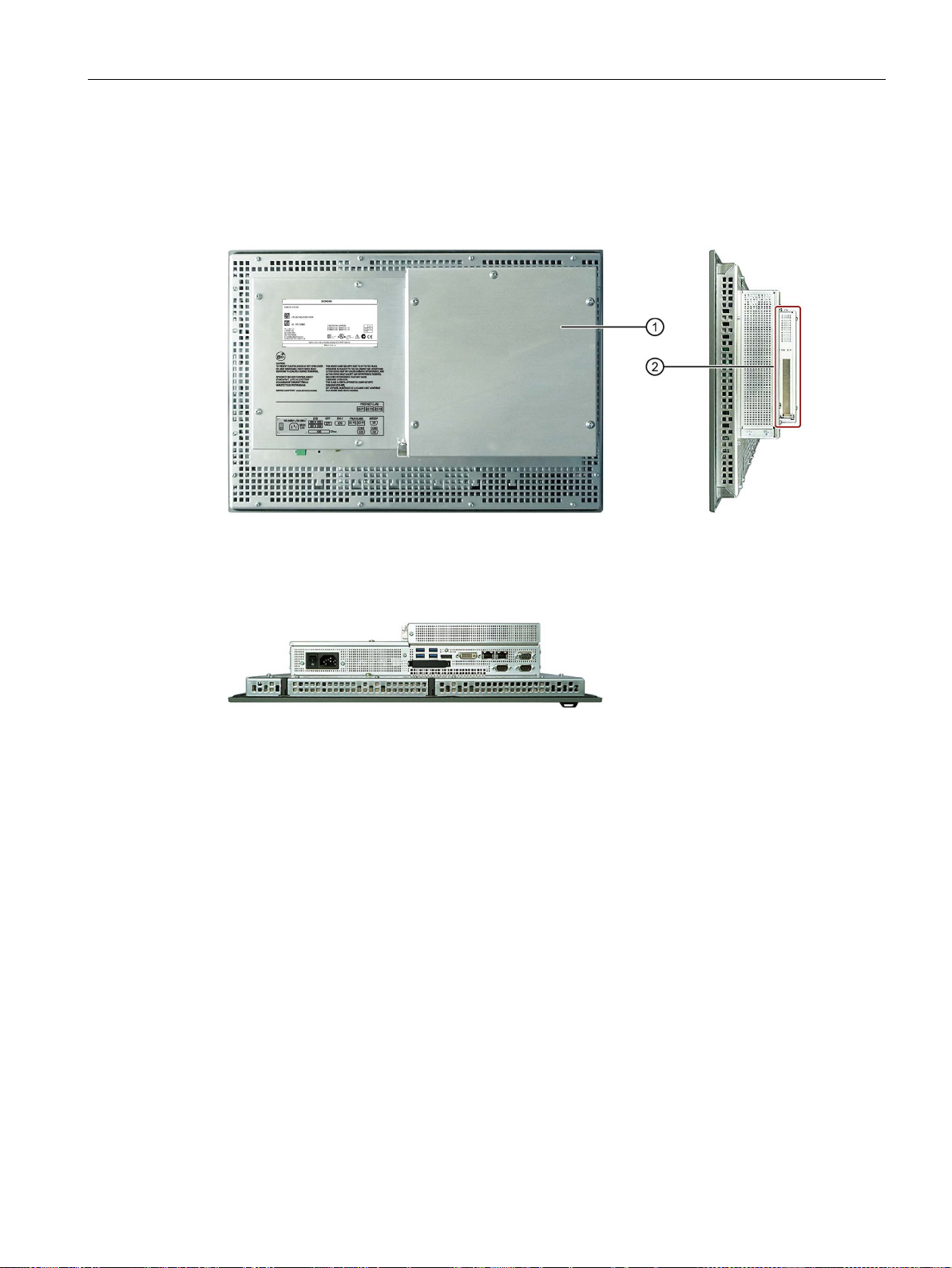
1.2.4
Devices with expansions
1.2.4.1
Devices with DVD drive
Rear view and side view
①
Rear panel
②
DVD drive
Bottom view
1.2 Design of the built-in units
The following figures show the 15" device with resistive single-touch screen as an example.
SIMATIC IPC477D, IPC477D PRO
20 Operating Instructions, 11/2016, A5E31347228-AF
Overview
1.2.4.2
Devices with PCIe card
Rear view and side view
①
Rear panel
②
PCIe card
Bottom view
1.2 Design of the built-in units
The following figures show the 15" device with resistive single-touch screen as an example.
SIMATIC IPC477D, IPC477D PRO
Operating Instructions, 11/2016, A5E31347228-AF
21
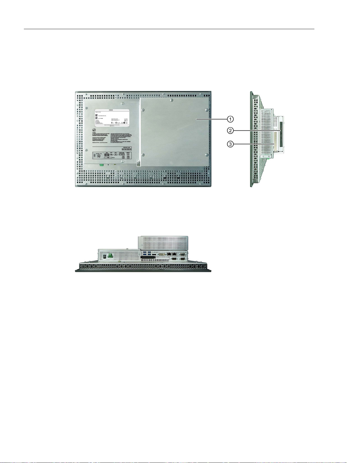
Overview
1.2.4.3
Devices with PCIe card and with DVD drive
Rear view and side view
①
Rear panel
②
DVD drive
③
PCIe card
Bottom view
1.2 Design of the built-in units
The following figures show the 15" device with resistive single-touch screen as an example.
SIMATIC IPC477D, IPC477D PRO
22 Operating Instructions, 11/2016, A5E31347228-AF
Overview
1.2.5
Operator controls or touch/key devices with resistive single-touch screen
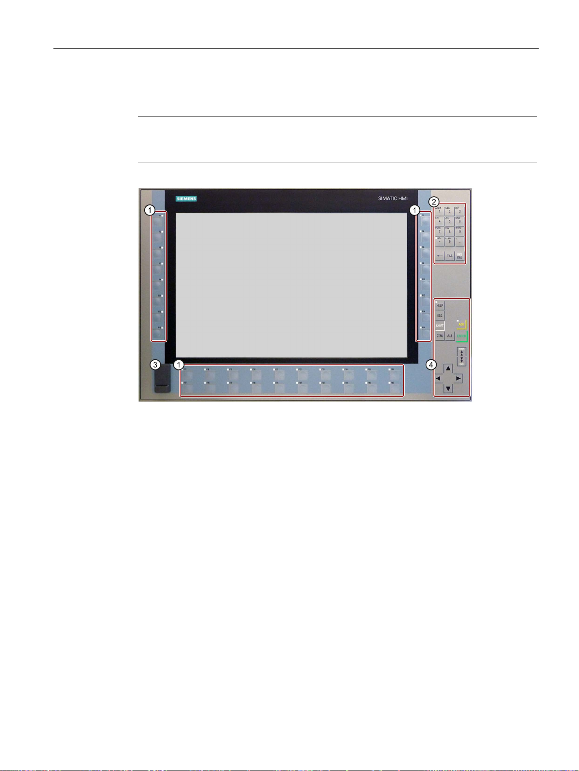
Note
If you open the sealed cover for the front USB port, the degree of protection
front of the device is no longer guaranteed.
①
Function keys
②
Keypad with alphanumeric and numeric keys
③
Sealed cover for the USB port
④
Control keys, cursor keys, On/Off switch
1.2 Design of the built-in units
IP65 for the
SIMATIC IPC477D, IPC477D PRO
Operating Instructions, 11/2016, A5E31347228-AF
23
Overview
1.2.6
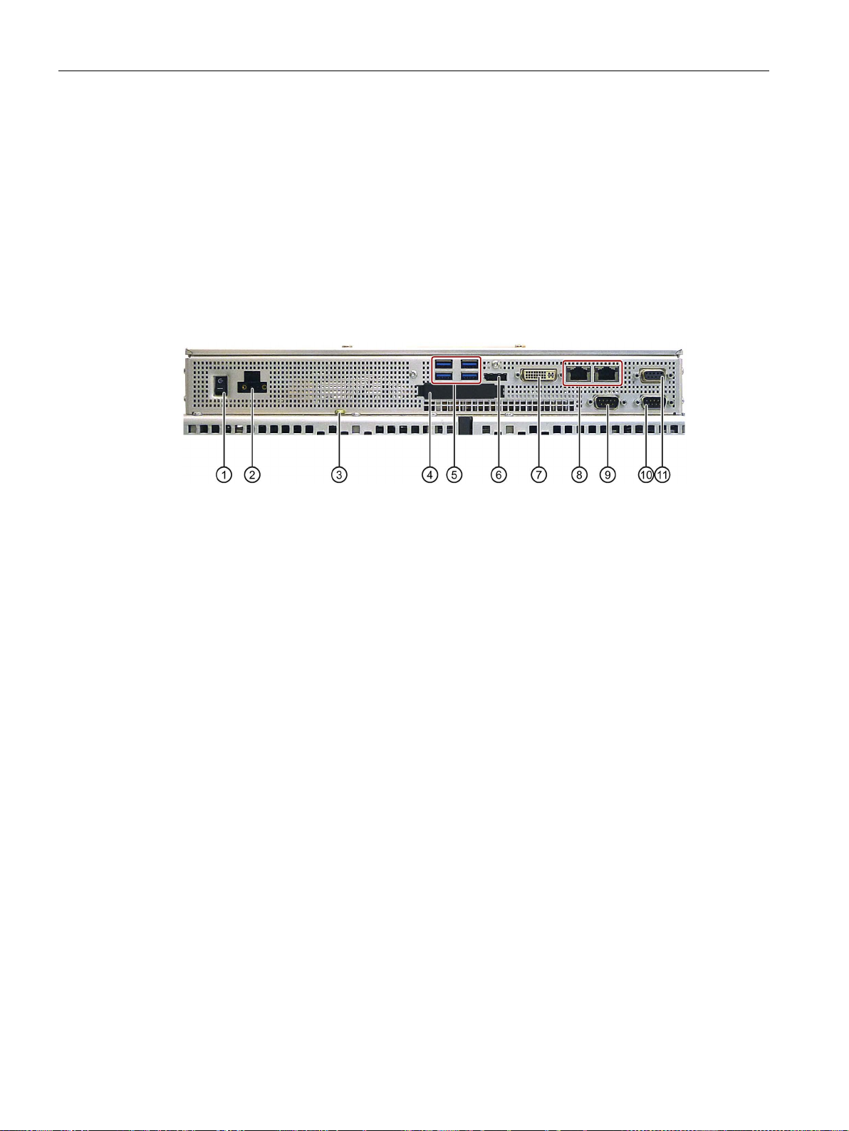
Interfaces and operator controls for devices with 24 V DC power supply
Devices with PROFIBUS interface
①
On/Off switch
②
24 V DC power supply
③
Protective conductor connection
④
Slot for external CFast card
With cover
⑤
4 x USB port
USB 3.0 high speed/high current
⑥
Display port
⑦
⑧
⑨
COM 1 port
Serial interface, 9-pin D-sub plug
⑩
COM 2 port
Serial interface, 9-pin D-sub plug
⑪
1.2 Design of the built-in units
The figures showing the interfaces apply to the following devices:
● IPC477D with 12" display
● IPC477D with 15" display
● IPC477D with 19" display
● IPC477D with 22" display
DVI-I port DVI connector for CRT or LCD monitor (VGA via
DVI-VGA adapter) with DVI interface
2 x Ethernet port RJ45 Ethernet connection 1 for 10/100/1000 Mbps or
RJ45 Ethernet connection 2 for 10/100/1000 Mbps
(not for PROFINET device)
PROFIBUS DP/MPI interface PROFIBUS DP/MPI interface RS 485, isolated,
9-pin D-sub socket
24 Operating Instructions, 11/2016, A5E31347228-AF
SIMATIC IPC477D, IPC477D PRO
Overview
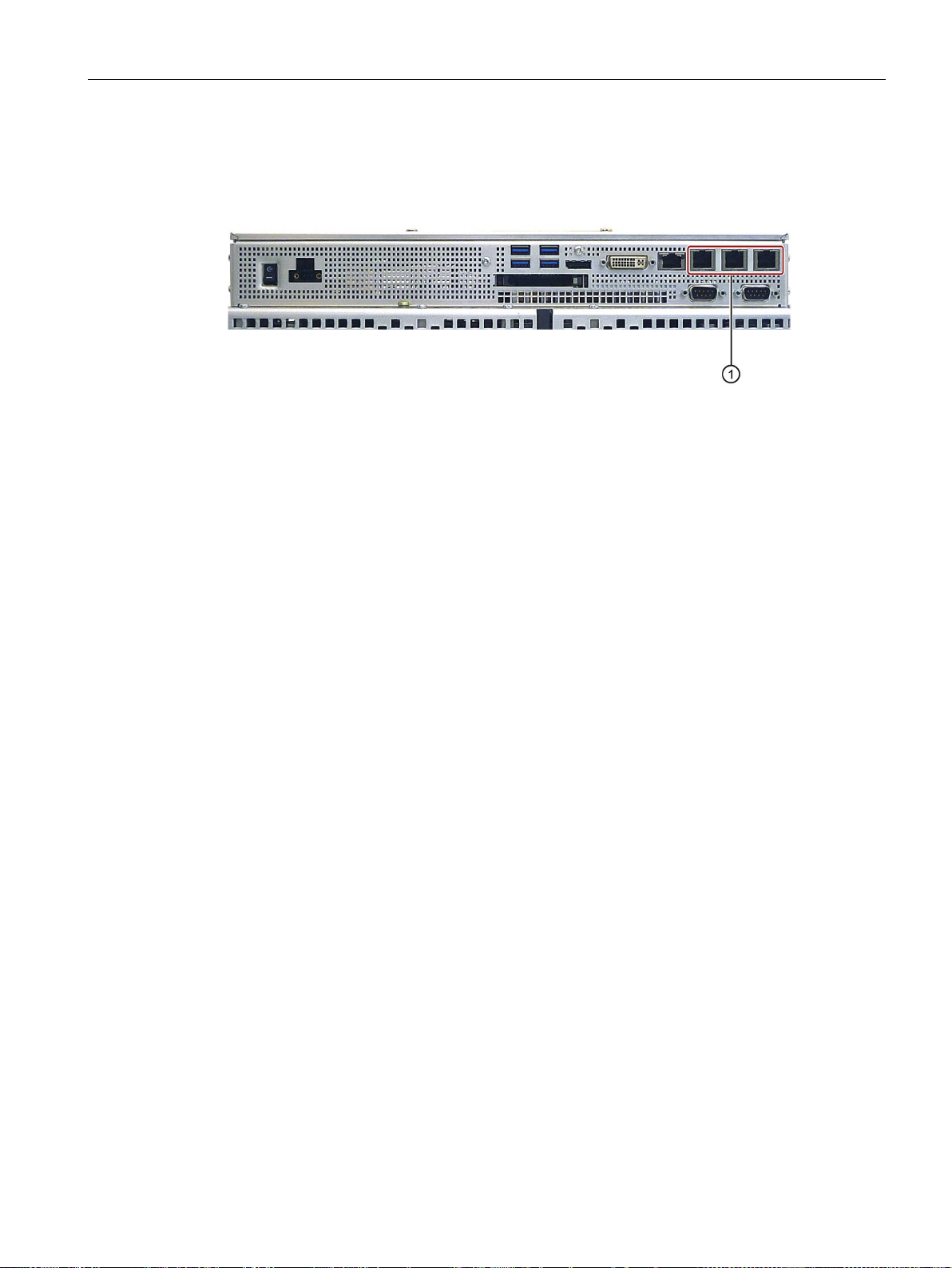
Devices with PROFINET interfaces
①
3 x PROFINET interfaces
CP-1616 onboard ports via RJ45 socket
1.2 Design of the built-in units
The unnamed interfaces in the following figure are identical to those on the PROFIBUS
device.
SIMATIC IPC477D, IPC477D PRO
Operating Instructions, 11/2016, A5E31347228-AF
25
Overview
1.2.7
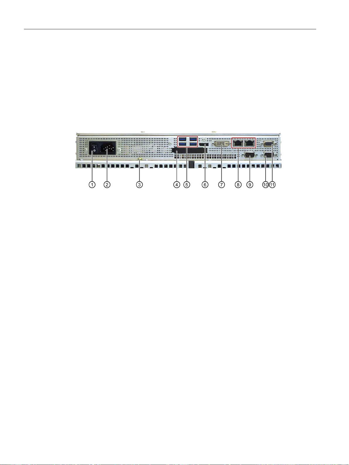
Interfaces and operator controls for devices with 240 V AC power supply
Devices with PROFIBUS interface
①
On/Off switch
② 240 V AC power supply
③
Protective conductor connection
④
Slot for external CFast card
With cover
⑤
4 x USB port
USB 3.0 high speed/high current
⑥
Display port
⑦
DVI-VGA adapter) with DVI interface
⑧
PROFINET device)
⑨
COM 1 port
Serial interface, 9-pin D-sub plug
⑩
COM 2 port
Serial interface, 9-pin D-sub plug
⑪
9-pin D-sub socket
1.2 Design of the built-in units
The figures showing the interfaces apply to the following devices:
● IPC477D with 15" display
● IPC477D with 19" display
● IPC477D with 22" display
DVI-I port DVI connector for CRT or LCD monitor (VGA via
2 x Ethernet port RJ45 Ethernet connection 1 for 10/100/1000 Mbps or
RJ45 Ethernet connection 2 for 10/100/1000 Mbps (not for
PROFIBUS DP/MPI interface
PROFIBUS DP/MPI interface RS 485, isolated,
SIMATIC IPC477D, IPC477D PRO
26 Operating Instructions, 11/2016, A5E31347228-AF

Overview
Devices with PROFINET interfaces
①
3 x PROFINET interface
CP-1616 onboard ports via RJ45 socket
1.2 Design of the built-in units
The unnamed interfaces in the following figure are identical to those on the PROFIBUS
device.
SIMATIC IPC477D, IPC477D PRO
Operating Instructions, 11/2016, A5E31347228-AF
27
Overview
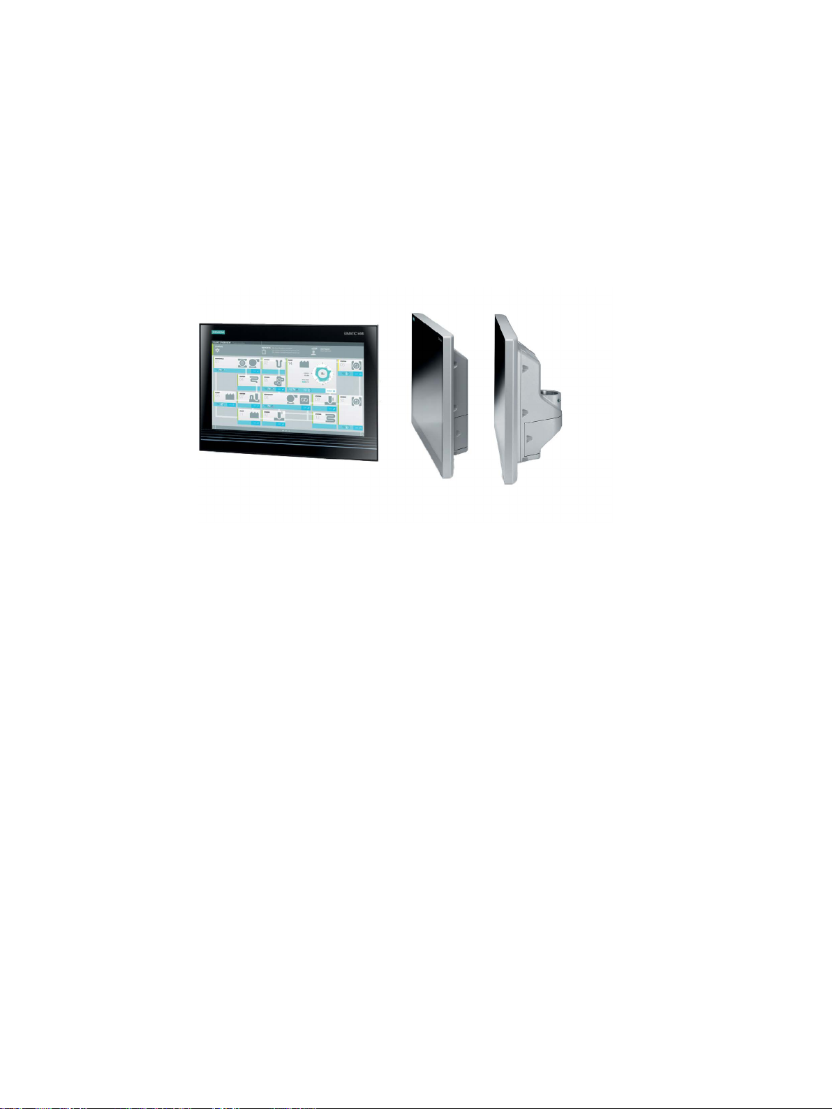
1.3
Design of the PRO device
Front view and side view
①
Display with multi-touch screen
②
Enclosure
③
Backplane cover
④
Terminal compartment cover
Bottom view
①
Mechanical interface for mounting/base adapter
1.3 Design of the PRO device
SIMATIC IPC477D, IPC477D PRO
28 Operating Instructions, 11/2016, A5E31347228-AF
Overview
Rear view - device version "prepared for stand/extension elements"
①
Backplane cover
②
Terminal compartment cover
③
Mechanical interface for mounting/base adapter
Bottom view - device version "prepared for stand/extension elements"
①
Cover plate
1.3 Design of the PRO device
SIMATIC IPC477D, IPC477D PRO
Operating Instructions, 11/2016, A5E31347228-AF
29
Overview
Rear view - device version "prepared for support arm and extension elements"
①
Terminal compartment cover
Note
The device version "prepared for support arm and extension elements" is intended for
devices with an extension element.
1.3 Design of the PRO device
SIMATIC IPC477D, IPC477D PRO
30 Operating Instructions, 11/2016, A5E31347228-AF
 Loading...