

Siemens SIMATIC IPC427E, SIMATIC IPC427D Quick Install Manual
Gerät einbauen
2
1
2
1
1
2
3
5
4
3
Mounting the device
12
Gerät anschließen
Connecting the device
1.1
Qualifiziertes Personal – Qualified Personnel
Das zu dieser Dokumentation zugehörige Produkt/System darf nur von für die jeweilige Aufgabenstellung qualifiziertem Personal gehandhabt werden unter Beachtung der für die jeweilige Aufgabenstellung zugehörigen Dokumentation, insbesondere der darin enthaltenen Sicherheits- und Warnhinweise.
Qualifiziertes Personal ist auf Grund seiner Ausbildung und Erfahrung befähigt, im Umgang mit diesen
Produkten/Systemen Risiken zu erkennen und mögliche Gefährdungen zu vermeiden.
The product/system described in this documentation may be operated only by personnel qualified for
the specific task in accordance with the relevant documentation, in particular its warning notices and
safety instructions. Qualified personnel are those who, based on their training and experience, are
capable of identifying risks and avoiding potential hazards when working with these products/systems.
http://support.automation.siemens.com
Zulässige Einbaulagen – Valid Mounting positions
1.2
Temperaturen für Gerät mit CFast- Karte, ohne PCI-Kar ten, installiert in RA L
Temperatures valid for device with CFast card, without PCI cards, installed in R AL
RAL = Restricted Access Location - e. g. a lockable cabinet
Betriebsstätte mit beschränktem Zutritt - z. B. ein abschließbarer Schaltschrank
50 °C
0 °C
35 °C
0 °C
45 °C
0 °C
45 °C
0 °C
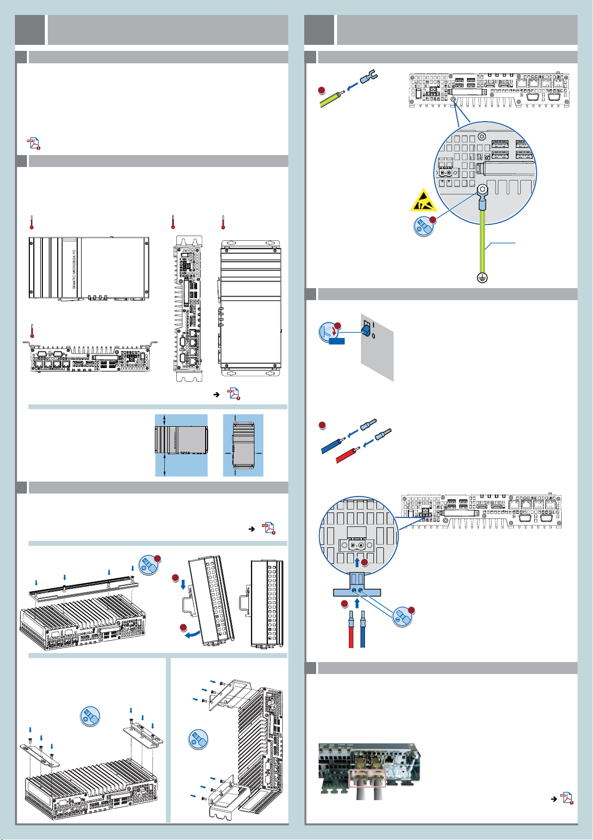
Schutzleiter anschließen – Connecting the protective earth
2.1
Stromversorgung anschließen – Connecting the power supply
2.2
0/OFF
M4
DC 24 V
Power
Supply
T20
Das Gerät darf nur an eine DC-24 -V-Stromversorgung angeschlossen werden, die den Anforderungen einer sicheren Kleinspannung
(SELV) gemäß der IEC/EN/DIN EN/UL 60950-1 entspricht.
Die Stromversorgung muss die Anforderung NEC Class 2 bz w. LPS
gemäß der IEC/EN/DIN EN/UL 60950-1 erfüllen.
2,5 mm²
Informationen zu weiteren Gerätevarianten in der Betriebsanleitung
Information on additional device variants in operating instructions
Erforderlicher Freiraum um das Gerät
Free space required around the device
Gerät anbauen – Mounting the device
1.3
Stellen Sie sicher, dass die Anschraubfläche an der Wand das Vierfache des Gesamtgewichts des
Geräts einschließlich Befestigungselemente tragen kann.
Verwenden Sie nur die in der Betriebsanleitung angegebenen Dübel und Schrauben.
Ensure that the mounting surface on the wall can bear four times the total
weight of the device, including fixing elements.
Use only the anchors and screws specified in the operating instructions.
Hutschienenmontage
Mounting on DIN rails
Wandmontage
Wall mounting
T20
T20
50 mm
100 mm
Buchmontage
Upright mounting
50 mm
50 mm
50 mm
2
50 mm
The device must only be connected to a 24 VDC power supply
which satisfies the requirements of safety extra low voltage (SELV)
according to IEC/EN/DIN EN/UL 60950 -1.
The power supply must meet the NEC Class 2 or LPS requirement in
accordance with IEC/EN/DIN EN/UL 60 950-1.
L+ M
0.5 x 3
Leitungen sichern – Securing the cables
2.3
Sichern Sie die angeschlossenen Leitungen zur Zugentlastung mit Kabelbindern an den markierten
Befestigungselementen. Achten Sie darauf, dass die Leitungen durch die Kabelbinder nicht gequetscht
werden. Beispiel:
Use cable ties to secure the connected cables to the selected fixing elements for strain relief.
Make sure that the cables are not crushed by the cable tie. Example:
T20
Weitere Beispiele in der Betriebsanleitung
Additional examples in operating instructions
1
2
3
2
1
1
3
Gerät in Betrieb nehmen
Commissioning the device
3
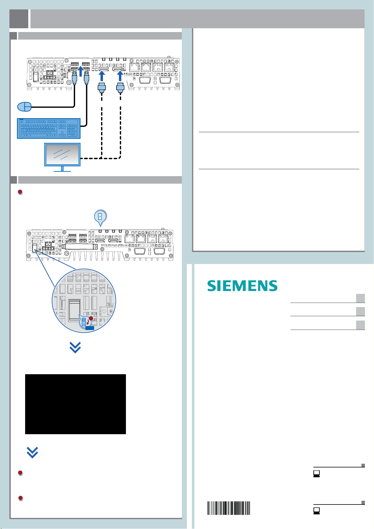
Maus, Tastatur, Monitor anschließen – Connecting mouse, keyboard, monitor
3.1
USB
DisplayPort
Gerät einschalten – Switching on the device
3.2
Schalten Sie den Ein-/Aus-Schalter in Position " I".
Die LED „PC ON/WD“ leuchtet.
Set the on/off switch to position "I".
The ‘PC ON/ WD‘ LED lights up.
PC ON/
WD
Abbildungen
Das vorliegende Dokument enthält Abbildungen zu den beschr iebenen Geräten und Zubehör.
Die Abbildungen können bezogen auf das geliefer te Gerät und Zubehör in Einzelheiten abweichen.
Illustrations
This document contains illustrations of the described devic es and accessories.
The illustrations may deviate from the particular ities of the delivered device and accessories.
Haftungsausschluss
Wir haben den Inhalt der Druckschrift auf Übereinstimmung mit der beschriebenen Hard- und
Software geprüft. Dennoch können Abweichungen nicht ausgeschlossen werden, so dass wir für
die vollständige Übereinstimmung keine Gewähr übernehmen. Die Angaben in dieser Druckschrif t
werden regelmäßig überprüft, notwendige Korrekturen sind in den nachfolgenden Auflagen
enthalten.
Disclaimer of Liability
We have reviewed the contents of this publication to ensure consistency with the hardware and
software described. Since variance cannot be precluded entirely, we cannot guarantee full
consistency. However, the information in this publication is reviewed regularly and any necessar y
corrections are included in subsequent editions.
Siemens AG
Industry Sector
Postfach 48 48
90026 NÜRNBERG
Press ESC for Boot Options
Warten Sie bis die Meldung erlischt.
Wait for the message to disappear.
Self-Test
1/ON
Gerät einbauen
Mounting the device
Gerät anschließen
Connecting the device
SIMATIC
Industrial PC
Gerät in Betrieb nehmen
Commissioning the device
1
SIMATIC IPC427E
Quick Install Guide
Technische Support-Zentrale
Central Technical Support
www.siemens.com/
automation/support
Folgen Sie den Anweisungen auf dem Bildschirm.
Follow the instruc tions on the screen.
08/2016
A5E37454815-AA
Reparatur und Ersatzteile
Service and spare parts
www.automation.
siemens.com/service
 Loading...