

Siemens SIMATIC IPC427D Operating Instructions Manual

___________________
___________________
___________________
___________________
___________________
___________________
___________________
___________________
___________________
___________________
___________________
___________________
SIMATIC
Industrial PC
SIMATIC IPC427D
Operating Instructions
05/2017
A5E31347215
Preface
Overview
1
Safety Instructions
2
Installing and connecting the
device
3
Commissioning the device
4
Extended device functions
5
Expanding and assigning
parameters to the device
6
Device maintenance and
repair
7
Technical specifications
8
Technical support
A
Markings and symbols
B
List of abbreviations
C
-AB

Siemens AG
Division Digital Factory
Postfach 48 48
90026 NÜRNBERG
GERMANY
A5E31347215-AB
Ⓟ
Copyright © Siemens AG 2017.
All rights reserved
Legal information
Warning notice system
DANGER
indicates that death or severe personal injury will result if proper precautions are not taken.
WARNING
indicates that death or severe personal injury may result if proper precautions are not taken.
CAUTION
indicates that minor personal injury can result if proper precautions are not taken.
NOTICE
indicates that property damage can result if proper precautions are not taken.
Qualified Personnel
personnel qualified
Proper use of Siemens products
WARNING
Siemens products may only be used for the applications described in the catalog and in the relevant technical
maintenance are required to ensure that the products operate safely and without any problems. The permissible
ambient conditions must be complied with. The information in the relevant documentation must be observed.
Trademarks
Disclaimer of Liability
This manual contains notices you have to observe in order to ensure your personal safety, as well as to prevent
damage to property. The notices referring to your personal safety are highlighted in the manual by a safety alert
symbol, notices referring only to property damage have no safety alert symbol. These notices shown below are
graded according to the degree of danger.
If more than one degree of danger is present, the warning notice representing the highest degree of danger will
be used. A notice warning of injury to persons with a safety alert symbol may also include a warning relating to
property damage.
The product/system described in this documentation may be operated only by
task in accordance with the relevant documentation, in particular its warning notices and safety instructions.
Qualified personnel are those who, based on their training and experience, are capable of identifying risks and
avoiding potential hazards when working with these products/systems.
Note the following:
documentation. If products and components from other manufacturers are used, these must be recommended
or approved by Siemens. Proper transport, storage, installation, assembly, commissioning, operation and
All names identified by ® are registered trademarks of Siemens AG. The remaining trademarks in this publication
may be trademarks whose use by third parties for their own purposes could violate the rights of the owner.
We have reviewed the contents of this publication to ensure consistency with the hardware and software
described. Since variance cannot be precluded entirely, we cannot guarantee full consistency. However, the
information in this publication is reviewed regularly and any necessary corrections are included in subsequent
editions.
for the specific
07/2017 Subject to change

Preface
Purpose of the Operating Instructions
Basic knowledge required
Scope of the operating instructions
Approbations
CE marking
Standards
Position in the information landscape
These operating instructions contain all the information you need to commission and operate
the SIMATIC IPC427D.
It is intended both for programming and testing personnel who commission the device and
connect it with other units (automation systems, programming devices), as well as for service
and maintenance personnel who install add-ons or carry out fault/error analyses.
A solid background in personal computers and Microsoft operating systems is required to
understand this manual. General knowledge in the field automation control engineering is
recommended.
These operating instructions are valid for all versions of the SIMATIC IPC427D.
You will find additional information in "Certificates and approvals (Page 105)".
You will find additional information in "Certificates and approvals (Page 105)".
For more information, refer to chapters "Certificates and approvals (Page 105)" and
"Technical specifications (Page 115)".
The IPC documentation comprises:
● SIMATIC IPC427D Quick Install Guide, containing product information related to the
device, e.g. important notes
SIMATIC IPC427D
Operating Instructions, 05/2017, A5E31347215-AB
● SIMATIC IPC427D Operating Instructions
The documentation is supplied with the IPC in multiple languages in electronic form as a
PDF file on the USB stick supplied in the documentation package.
3

Preface
Conventions
Note
A note is important information about
specific sections of the documentation that require special consideration.
History
Edition
Comments
01/2013
First edition
05/2017
Update for converting from DVD to USB stick
Guideline to the operating instructions
Content structure
Contents
Preface
Purpose, layout and description of the important topics
and chapters
device
The terms "PC" and "device" are sometimes used to refer to the SIMATIC IPC427D in this
documentation.
The term "Windows Embedded Standard" is used throughout to refer to "Windows
Embedded Standard 7". "Windows 7" is used as an abbreviation for "Windows 7 Ultimate".
the product, handling the product or a reference to
The following editions of these operating instructions have already been published:
Table of contents Detailed organization of the documentation, including the index of pages
Overview
Safety instructions All generally valid safety aspects:
Installing and connecting the device
Commissioning the
• Description of the product: Characteristics and field of application
• Product package
• Structure of the product/system: Operator control and connection ele-
ments
• Accessories, if available
• Legal requirements
• Product/system view during installation
• General information on commissioning
• Notes on operation
• Application planning: Aspects of storage, transport, environmental and
EMC conditions to be considered in the preparatory stage.
• Installation: Product installation options and installation instructions
• Connection: Options of connecting the product and wiring instructions
• Integration: Options of integrating the product into existing or planned
automation systems and networks.
Commissioning the product/system
SIMATIC IPC427D
4 Operating Instructions, 05/2017, A5E31347215-AB

Preface
Content structure
Contents
tions
device
Abbreviations
Abbreviations of the technical terms used
Extended device func-
Expanding and assigning parameters to the
Device maintenance
and repair
Technical specifications
Technical support
Monitoring and display functions
Procedure for installing device expansions (modules, drives)
• Replacing hardware components
• Restoring and setting up the operating system and BIOS (Recovery)
• Installing drivers and software
• Service and spare parts
• Recycling and disposal
• General specifications in compliance with relevant standards and cur-
rent/voltage values
• Guidelines and certifications, ESD guidelines, notes on retrofitting
• Dimension drawings: Dimensions of the device and of modules
• Detailed descriptions of boards and system resources
• Service and support
• Troubleshooting: Problems, causes, remedy
• BIOS Setup
SIMATIC IPC427D
Operating Instructions, 05/2017, A5E31347215-AB
5

Preface
SIMATIC IPC427D
6 Operating Instructions, 05/2017, A5E31347215-AB

Table of contents
Preface ................................................................................................................................................... 3
1 Overview............................................................................................................................................... 13
2 Safety Instructions ................................................................................................................................ 21
3 Installing and connecting the device ...................................................................................................... 27
1.1 Product description ................................................................................................................. 13
1.1.1 Applications ............................................................................................................................. 14
1.1.2 Features .................................................................................................................................. 14
1.2 Design of the device ............................................................................................................... 17
1.2.1 Interfaces and operating elements ......................................................................................... 17
1.2.2 Status displays ........................................................................................................................ 19
1.3 Accessories ............................................................................................................................. 20
2.1 General safety instructions ..................................................................................................... 21
2.2 Notes on usage ....................................................................................................................... 25
3.1 Preparing for installation ......................................................................................................... 27
3.1.1 Checking the delivery package ............................................................................................... 27
3.1.2 Identification data of the device .............................................................................................. 29
3.1.3 Permitted mounting positions ................................................................................................. 31
3.2 Installing the device ................................................................................................................ 33
3.2.1 Mounting instructions .............................................................................................................. 33
3.2.2 Installation on a DIN rail .......................................................................................................... 35
3.2.2.1 Attaching the DIN rail bracket ................................................................................................. 35
3.2.2.2 Mounting on DIN rails ............................................................................................................. 36
3.2.3 Wall mounting ......................................................................................................................... 37
3.2.4 Upright mounting ..................................................................................................................... 38
3.3 Connecting the device ............................................................................................................ 39
3.3.1 Notes on connecting ............................................................................................................... 39
3.3.2 Connecting the protective conductor ...................................................................................... 41
3.3.3 Connecting peripheral equipment ........................................................................................... 42
3.3.4 Connecting expansion cards .................................................................................................. 43
3.3.5 Connecting the terminal .......................................................................................................... 44
3.3.6 Connecting the power supply ................................................................................................. 45
3.3.7 Connecting the device to networks ......................................................................................... 46
3.3.8 PROFINET .............................................................................................................................. 48
3.3.9 Installing the strain relief ......................................................................................................... 50
3.3.10 Securing the lines ................................................................................................................... 51
SIMATIC IPC427D
Operating Instructions, 05/2017, A5E31347215-AB
7

Table of contents
4 Commissioning the device .................................................................................................................... 53
5 Extended device functions .................................................................................................................... 59
6 Expanding and assigning parameters to the device ............................................................................... 71
7 Device maintenance and repair ............................................................................................................. 81
4.1 General information on commissioning ................................................................................. 53
4.2 Switching on the device ......................................................................................................... 54
4.3 Windows Action Center .......................................................................................................... 55
4.4 SIMATIC IPC Wizard ............................................................................................................. 56
5.1 Monitoring Functions .............................................................................................................. 59
5.1.1 Introduction ............................................................................................................................ 59
5.1.2 Temperature monitoring/display ............................................................................................ 60
5.1.3 Watchdog (WD)...................................................................................................................... 61
5.1.4 Battery monitoring .................................................................................................................. 62
5.2 Enhanced Write Filter ............................................................................................................ 63
5.3 File Based Write Filter (FBWF) .............................................................................................. 66
5.4 Buffer memory MRAM ........................................................................................................... 68
5.5 Operation without monitor and keyboard ............................................................................... 68
5.6 Active Management Technology (AMT) ................................................................................ 68
5.7 Trusted Platform Modul (TPM) ............................................................................................... 70
6.1 Installing and removing the memory module ......................................................................... 71
6.1.1 Opening the device ................................................................................................................ 71
6.1.2 Opening the device containing expansion cards ................................................................... 73
6.1.3 Replacing memory modules .................................................................................................. 74
6.2 Installing and removing CFast cards...................................................................................... 76
6.3 Installing and removing PCIe cards ....................................................................................... 78
7.1 Maintenance ........................................................................................................................... 81
7.2 Repair information .................................................................................................................. 81
7.3 Installing and removing hardware .......................................................................................... 84
7.3.1 Installing and removing the backup battery ........................................................................... 84
7.3.2 Changing storage media ........................................................................................................ 87
7.3.2.1 Replacing a HDD/SSD ........................................................................................................... 87
7.3.2.2 Installing a memory card fitting .............................................................................................. 90
7.4 Installing the software ............................................................................................................ 92
7.4.1 Reinstalling the operating system .......................................................................................... 92
7.4.1.1 General installation procedure ............................................................................................... 92
7.4.1.2 Restoring the factory state ..................................................................................................... 93
7.4.1.3 Windows 7 .............................................................................................................................. 94
7.4.1.4 Windows Embedded Standard 7 ........................................................................................... 98
7.4.2 Partitioning data media ........................................................................................................ 100
7.4.2.1 Partitioning in Windows Embedded Standard 7 .................................................................. 100
7.4.2.2 Partitioning in Windows 7 Ultimate ...................................................................................... 101
7.4.2.3 Adapting partitions in Windows 7 Ultimate and Windows Embedded Standard 7 .............. 101
SIMATIC IPC427D
8 Operating Instructions, 05/2017, A5E31347215-AB

Table of contents
8 Technical specifications ...................................................................................................................... 105
7.4.3 Installing drivers and software .............................................................................................. 102
7.4.4 Update installation ................................................................................................................ 103
7.4.4.1 Updating the operating system ............................................................................................. 103
7.4.4.2 Installing or updating user programs and drivers ................................................................. 103
7.4.4.3 CP 1616 onboard .................................................................................................................. 103
7.4.5 Backing up data .................................................................................................................... 104
7.5 Recycling and disposal ......................................................................................................... 104
8.1 Certificates and approvals .................................................................................................... 105
8.1.1 Australia Class B ................................................................................................................... 107
8.2 Declaration of conformity ...................................................................................................... 107
8.2.1 Electromagnetic compatibility, Industrial and Residential Areas .......................................... 107
8.3 Directives and declarations ................................................................................................... 108
8.3.1 ESD guideline ....................................................................................................................... 108
8.4 Dimension drawings .............................................................................................................. 111
8.4.1 Dimension drawing - mounting on a DIN rail ........................................................................ 111
8.4.2 Dimension drawing - wall-mounting ...................................................................................... 112
8.4.3 Dimension drawing - vertical mounting ................................................................................. 113
8.4.4 Dimension drawing - device with expansion cards ............................................................... 114
8.5 Technical specifications ........................................................................................................ 115
8.5.1 General technical specifications ........................................................................................... 115
8.5.2 Ambient conditions ................................................................................................................ 118
8.5.3 Power requirements of the components ............................................................................... 120
8.5.4 Integrated DC power supply ................................................................................................. 121
8.5.5 Typical power consumption .................................................................................................. 121
8.6 Hardware descriptions .......................................................................................................... 122
8.6.1 External ports ........................................................................................................................ 122
8.6.1.1 COM1/COM2 ........................................................................................................................ 122
8.6.1.2 CFast card ............................................................................................................................ 123
8.6.1.3 DisplayPort ............................................................................................................................ 124
8.6.1.4 DVI-I ...................................................................................................................................... 125
8.6.1.5 Ethernet ................................................................................................................................ 126
8.6.1.6 USB 3.0 port ......................................................................................................................... 126
8.6.1.7 PROFIBUS ............................................................................................................................ 127
8.6.1.8 PROFINET ............................................................................................................................ 127
8.6.1.9 CAN bus ................................................................................................................................ 128
8.6.2 Internal ports ......................................................................................................................... 129
8.6.2.1 PCIe card .............................................................................................................................. 129
8.6.3 System resources ................................................................................................................. 131
8.6.3.1 Currently allocated system resources ................................................................................... 131
8.6.3.2 Allocation of system resources ............................................................................................. 131
SIMATIC IPC427D
Operating Instructions, 05/2017, A5E31347215-AB
9

Table of contents
8.6.4 I/O Address Areas ................................................................................................................ 133
8.6.4.1 Overview of the internal module registers ........................................................................... 133
8.6.4.2 Watchdog enable register / 066h select register (read/write, address 062h) ...................... 133
8.6.4.3 Watchdog trigger register (read only, address 066h) .......................................................... 134
8.6.4.4 CAN base address register .................................................................................................. 134
8.6.4.5 Output register user LED L1/L2/L3 (read/write, address 404Eh) ........................................ 135
8.6.4.6 Battery status register (read-only, address 50Ch) ............................................................... 135
8.6.4.7 MRAM address register ....................................................................................................... 136
8.6.5 CP 1616 onboard communications processor ..................................................................... 137
8.6.5.1 Introduction .......................................................................................................................... 137
8.6.5.2 Firmware Loader .................................................................................................................. 139
8.6.5.3 Further actions in STEP 7/NCM PC..................................................................................... 141
8.7 BIOS description .................................................................................................................. 142
8.7.1 Overview .............................................................................................................................. 142
8.7.2 Starting BIOS Setup ............................................................................................................. 143
8.7.3 BIOS Setup menus .............................................................................................................. 144
8.7.4 Main menu ........................................................................................................................... 145
8.7.5 Advanced Menu ................................................................................................................... 146
8.7.6 Security menu ...................................................................................................................... 156
8.7.7 Power menu ......................................................................................................................... 157
8.7.8 Boot menu ............................................................................................................................ 159
8.7.9 Exit Menu ............................................................................................................................. 163
8.7.10 Default BIOS Setup entries .................................................................................................. 164
8.7.11 Alarm, error and system messages ..................................................................................... 167
8.7.12 Performing a BIOS update ................................................................................................... 167
8.8 Active Management Technology (AMT) .............................................................................. 168
8.8.1 Introduction .......................................................................................................................... 168
8.8.2 Overview of AMT.................................................................................................................. 169
8.8.3 Enabling Intel® AMT / basic configuration ........................................................................... 169
8.8.4 Resetting the Intel® AMT to the default settings and disabling AMT .................................. 171
8.8.5 Determining the network address ........................................................................................ 171
8.8.6 Forcing user consent ........................................................................................................... 172
8.9 Functional scope in Windows .............................................................................................. 173
8.9.1 Windows Embedded Standard 7 ......................................................................................... 173
SIMATIC IPC427D
10 Operating Instructions, 05/2017, A5E31347215-AB

Table of contents
A Technical support ................................................................................................................................ 175
B Markings and symbols ........................................................................................................................ 179
C List of abbreviations ............................................................................................................................ 183
Glossary ............................................................................................................................................. 189
Index................................................................................................................................................... 197
A.1 Service and support .............................................................................................................. 175
A.2 Troubleshooting .................................................................................................................... 176
A.3 Notes on the use of third-party modules ............................................................................... 177
B.1 Overview ............................................................................................................................... 179
B.2 Safety .................................................................................................................................... 179
B.3 Operator controls .................................................................................................................. 179
B.4 Certificates, approvals and markings .................................................................................... 180
B.5 Interfaces .............................................................................................................................. 181
B.6 Directives and declarations ................................................................................................... 182
SIMATIC IPC427D
Operating Instructions, 05/2017, A5E31347215-AB
11

Table of contents
SIMATIC IPC427D
12 Operating Instructions, 05/2017, A5E31347215-AB
1
1.1
Product description
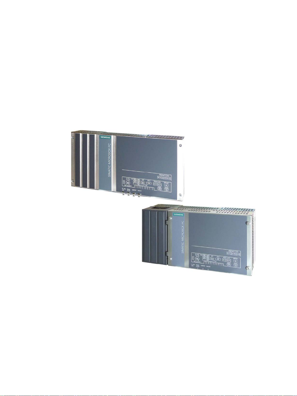
The SIMATIC IPC427D provides high-level industrial performance.
● Compact design
● Maintenance-free operation
● High degree of ruggedness
SIMATIC IPC427D
Operating Instructions, 05/2017, A5E31347215-AB
13

Overview
1.1.1
Applications
1.1.2
Features
Basic data
cards
max. 175 mm long
Power supply
24 V DC (-20%/+20%) max. 4 A
Conditions of use
Operation without fan
1.1 Product description
The device provides industrial PC systems for high-performance and space-saving
applications in particular in the field of machine, systems and switchgear cabinet
engineering:
● Measuring and controlling process and machine data, for example, automated washing
systems, assembling machines and packaging machines
● Operating and visualization tasks with separate monitors or displays, for example,
information terminals and large-scale displays in automotive production
● Data logging and processing, for example, system data logging and distributed process
control
Installation
Processor
Main memory
Free slots for expansion
Graphics
• Installation on a DIN rail
• Wall mounting
• Vertical mounting
• Intel Celeron 827E 1.4 GHz, 1.5 MB SLC
• Intel Core i3-3217UE 1.6 GHz, 3 MB SLC
• Intel Core i7-3517UE 1.7 GHz, 4 MB SLC
Memory modules without ECC:
• 1 GB DDR3-SDRAM SODIMM
• 2 GB DDR3-SDRAM SODIMM
• 4 GB DDR3-SDRAM SODIMM
• 8 GB DDR3-SDRAM SODIMM
Memory modules with ECC:
• 4 GB DDR3-ECC SODIMM
• 8 GB DDR3-ECC SODIMM
Up to 2 × PCIe cards, depending on enclosure version;
• Integrated Intel HD2000 or HD4000
• DVI resolution of 640 × 480 pixels up to 1920 × 1200 pixels
• Display port resolution max. 1920 × 1200 pixels
• Graphics memory is claimed in main memory (dynamic UMA)
SIMATIC IPC427D
14 Operating Instructions, 05/2017, A5E31347215-AB

Overview
Basic data
Drives and storage media
Hard disk
2.5", ≥ 250 GB, SATA
USB stick
External, can be connected via USB interface
Ports
COM2 (RS232); optional
DPP++: DisplayPort, DVI via DPP-to-DVI adapter
backward compatible with USB 2.0/1.1
1 × RJ45 (10/100/1000 Mbps) for PROFINET versions
PROFIBUS DP
12 Mbps (electrically isolated, compatible with CP 5622), optional
PROFINET
3 × RJ45 (10/100 Mbps), CP 1616 on-board, optional
CAN interface
Optional
Keyboard, mouse
Connected via external USB port
Extended device functions
user 1
Transient voltage interruption
Up to 15 ms buffer time at full load
TPM
Integrated Trusted Platform Module, optional, to TPM 1.2 standard
1.1 Product description
CFast card
• 2 GB optional or
• 4 GB optional or
• 8 GB optional or
• 16 GB optional
SSD (Solid State Disk) 2.5", ≥ 80 GB standard
Serial COM1 (RS232)
Graphics DVI-I: suitable for use as DVI or VGA
USB 4 × USB 3.0, simultaneous operation of max. 2 x high current ports,
Ethernet 2 × RJ45 (10/100/1000 Mbps), teaming capability, or
Temperature
• When permitted temperature range is exceeded
• Warnings can be analyzed by application program (local, via LAN)
Watchdog
• Monitoring function for program execution
• Restart can be parameterized in the event of a fault
• Warnings can be analyzed by application program (local, via LAN)
LED display 4 system status LEDs, of which three can be freely programmed by
Buffer memory 512 KB MRAM
1
optional
SIMATIC IPC427D
Operating Instructions, 05/2017, A5E31347215-AB
15

Overview
Software
Operating systems
1
pages of Customer Support.
See also
1.1 Product description
Available
Project-specific
For more information related to the control of the LEDs/MRAM on a Windows operating system,
refer to "Example programs for addressing the LEDs on Windows operating systems" on the FAQ
• Without
• Windows Embedded Standard 7
• Windows 7 Ultimate MUI
• LINUX
• QNX
• VxWorks
Output register user LED L1/L2/L3 (read/write, address 404Eh) (Page 135)
MRAM address register (Page 136)
Industry Automation and Drive Technologies - Homepage
(http://www.siemens.com/automation/service&support)
SIMATIC IPC427D
16 Operating Instructions, 05/2017, A5E31347215-AB
Overview
1.2
Design of the device
1.2.1
Interfaces and operating elements
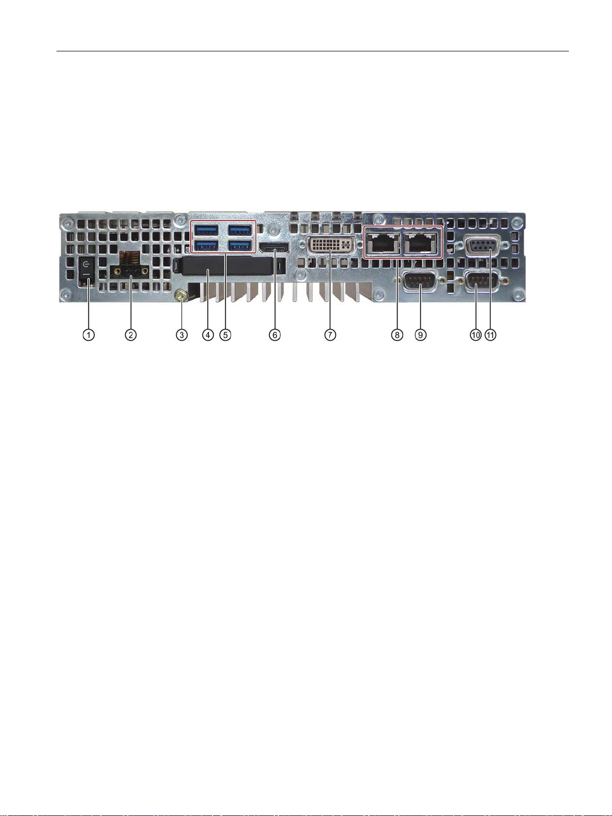
Device with PROFIBUS or CAN interface
①
"ON", when the "_" symbol is pressed. Position "OFF" is the delivery state.
②
24V DC
Power supply connection
③
Protective conductor
Protective conductor terminal
④
Memory card slot
Cover for the CFast card
⑤
4 × USB
USB 3.0 high current, backward compatible with USB 2.0/1.1
⑥
Display port
DisplayPort connection for digital monitor
⑦
DVI-I
DVI connector for CRT or LCD monitor with DVI port
⑧
with PROFINET versions)
⑨
COM1
Serial interface
⑩
COM2
Serial interface (optional)
⑪
CAN fieldbus
1.2 Design of the device
On/off switch The on/off switch does not isolate the device from the power supply. Position
2 × Ethernet RJ45 Ethernet connection 1 (exclusive PCI interrupt) for 10/100/1000 Mbps or
RJ45 Ethernet connection 2 (shared PCI interrupt) for 10/100/1000 Mbps (not
PROFIBUS DP/MPI or
PROFIBUS DP/MPI interface (RS 485, electrically isolated), 9-pin Sub-D socket or CAN fieldbus (optional; not for devices with PROFINET)
SIMATIC IPC427D
Operating Instructions, 05/2017, A5E31347215-AB
17
Overview
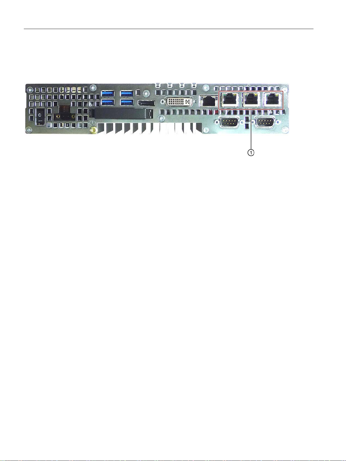
Device with PROFINET interfaces
①
PROFINET
CP 1616 onboard interface, three RJ45 sockets for devices with PROFINET
1.2 Design of the device
The interfaces not labeled in the diagram below are identical to those on the PROFIBUS
device.
SIMATIC IPC427D
18 Operating Instructions, 05/2017, A5E31347215-AB
Overview
1.2.2
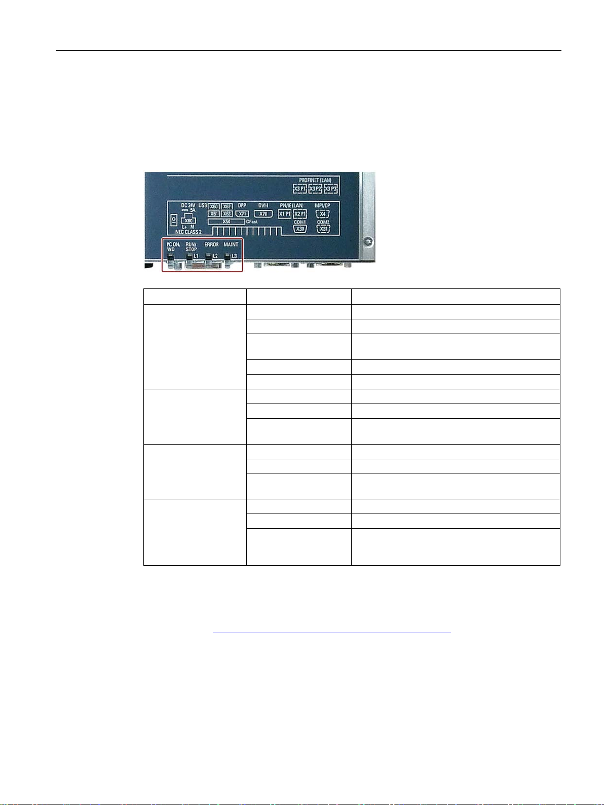
Status displays
Device with PROFIBUS
LED
State
Description
Off
-
Green
BIOS ready to boot
(1 Hz)
Yellow
Idle state
Flashing red (1 Hz)
Watchdog status display: active
Off
-
Green
Can be controlled by user program
Off
-
program (e.g. WinAC)
Off - Yellow
-
board CP1616 interface.
1.2 Design of the device
PC ON/WD
Flashing green/yellow
RUN/STOP / L1
Yellow Can be controlled by controller program (e.g.
ERROR / L2
Red Flashing red Can be controlled by user program or controller
MAINT /
L3
Red Can be controlled by controller program
BIOS in POST, power switch on
WinAC)
(e.g. WinAC) and shows group errors of the on-
For additional information on controlling the LEDs or the MRAM with a Windows operating
system, please refer to Output register user LED L1/L2/L3 (read/write, address 404Eh)
(Page 135). Example programs for controlling the LEDs on Windows operating systems are
available on the Customer Support page of Siemens Industry Automation and Drive
Technologies. (http://www.siemens.com/automation/service&support)
SIMATIC IPC427D
Operating Instructions, 05/2017, A5E31347215-AB
19
Overview
1.3
Accessories
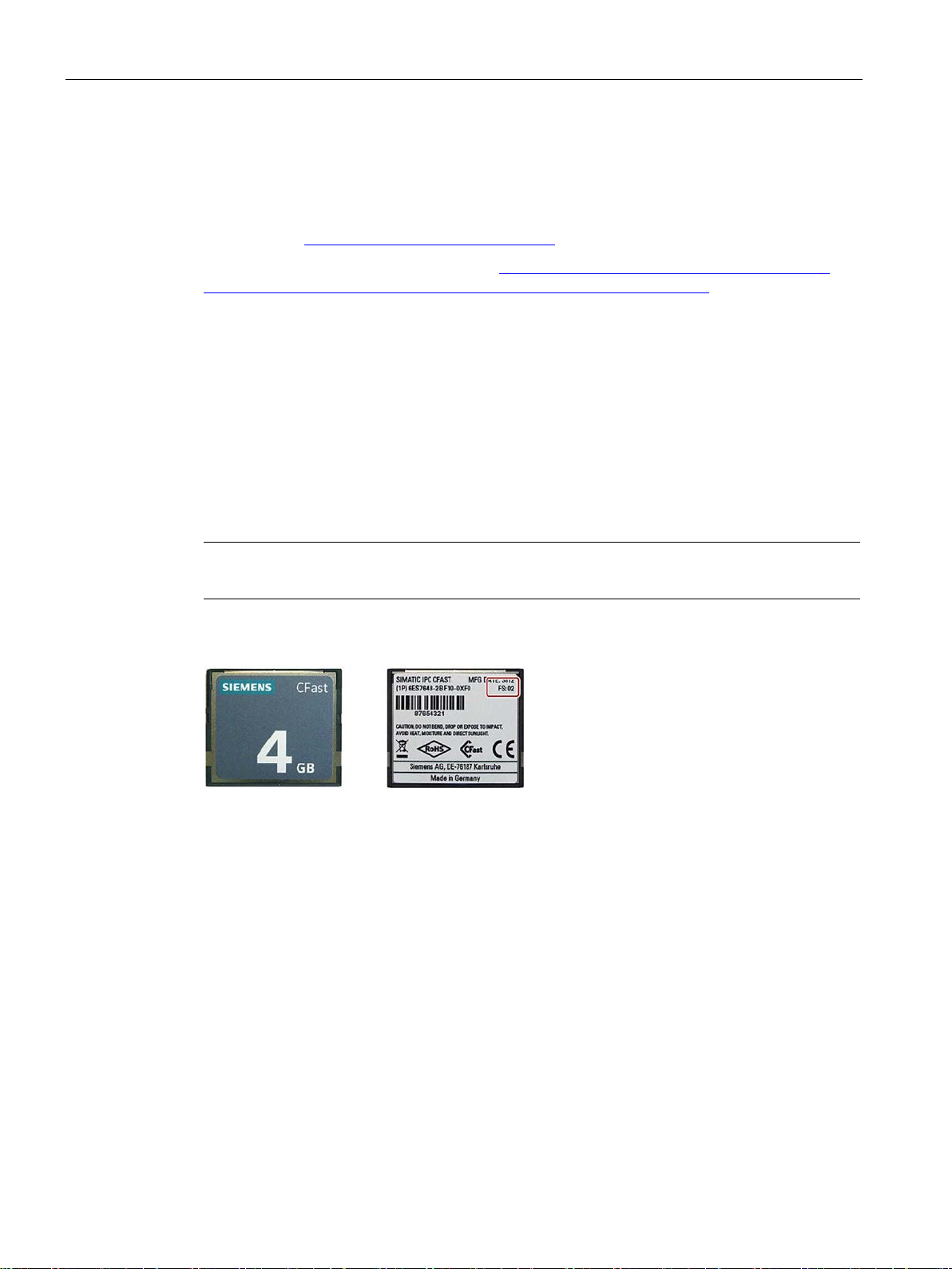
SIMATIC IPC CFast cards
Version of the SIMATIC IPC CFast card
Note
This device supports only SIMATIC IPC CFast cards with version
Memory modules
1.3 Accessories
Siemens offers accessories not included in the scope of delivery for the device. For more
information on available accessories, refer to the Internet at:
Industry Mall (http://mall.automation.siemens.com)
Expansion components and accessories (http://www.automation.siemens.com/mcms/pc-
based-automation/en/industrial-pc/expansion_components_accessories)
● 2 GB
● 4 GB
● 8 GB
● 16 GB
02 or higher.
The version ID is available on the label of the CFast card.
● SO-DIMM module 1024 MB DDR3 SDRAM or
● SO-DIMM module 2048 MB DDR3 SDRAM or
● SO-DIMM module 4096 MB DDR3 SDRAM or
● SO-DIMM module 8192 MB DDR3 SDRAM
SIMATIC IPC427D
20 Operating Instructions, 05/2017, A5E31347215-AB

2
2.1
General safety instructions
WARNING
Life-threatening voltages are present with an open control cabinet
System expansions
NOTICE
Damage through system expansions
When you install the device in a control cabinet, some areas or components in the open
control cabinet may be carrying life-threatening voltages.
If you touch these areas or components, you may be killed by electric shock.
Switch off the power supply to the cabinet before opening it.
Device and system expansions may be faulty and can affect the entire machine or plant.
The installation of expansions can damage the device, machine or plant. Device and
system expansions may violate safety rules and regulations regarding radio interference
suppression. If you install or exchange system expansions and damage your device, the
warranty becomes void.
SIMATIC IPC427D
Operating Instructions, 05/2017, A5E31347215-AB
21
Safety Instructions
NOTICE
"Open Type" UL508
WARNING
Risk of fire through expansion cards
Battery and rechargeable battery
WARNING
Risk of explosion and release of harmful substances
2.1 General safety instructions
Note the following for system expansions:
● Only install system expansion devices designed for this device. Contact your technical
support team or where you purchased your PC to find out which system expansion
devices may safely be installed.
● Observe the information on electromagnetic compatibility (Page 107).
Note that the device is classified as "Open Type" for use in the area of Industrial Control
Equipment (UL508). Installation of the device in an enclosure complying with UL508 for
specific permitted mounting positions (see corresponding section) is a prerequisite for
approval or operation in accordance with UL508.
Expansion cards generate additional heat. The device may overheat and cause a fire.
Please note the following:
• Observe the safety and installation instructions for the expansion cards.
• If in doubt, install the device in an enclosure that is compliant with sections 4.6 and 4.7.3
of the IEC/UL/EN/DIN-EN 60950-1 standard.
Improper handling of lithium batteries can result in an explosion of the batteries.
Explosion of the batteries and the released pollutants can cause severe physical injury.
Worn batteries jeopardize the function of the device.
Note the following when handling lithium batteries:
• Replace used batteries in good time; see the section "Replacing the backup battery" in
the operating instructions.
• Replace the lithium battery only with an identical battery or types recommended by the
manufacturer (order no.: A5E00331143).
• Do not throw lithium batteries into fire, do not solder on the cell body, do not recharge,
do not open, do not short-circuit, do not reverse polarity, do not heat above 100°C and
protect from direct sunlight, moisture and condensation.
SIMATIC IPC427D
22 Operating Instructions, 05/2017, A5E31347215-AB

Safety Instructions
High frequency radiation
NOTICE
Unintentional operating situations
ESD Guideline
NOTICE
Electrostatic sensitive devices (ESD)
2.1 General safety instructions
High frequency radiation, e g. from a cellular phone, interferes with device functions and
can result in malfunctioning of the device.
Persons are injured and the plant is damaged.
Avoid high-frequency radiation:
• Remove radiation sources from the environment of the device.
• Switch off radiating devices.
• Reduce the radio output of radiating devices.
• Observe the information on electromagnetic compatibility (Page 107).
Electrostatic sensitive devices can be labeled with an appropriate symbol.
When you touch electrostatic sensitive components, you can destroy them through voltages
that are far below the human perception threshold.
If you work with components that can be destroyed by electrostatic discharge, observe the
ESD Guideline (Page 108).
SIMATIC IPC427D
Operating Instructions, 05/2017, A5E31347215-AB
23

Safety Instructions
Industrial Security
Disclaimer for third-party software updates
Notes on protecting administrator accounts
See also
2.1 General safety instructions
Siemens provides products and solutions with industrial security functions that support the
secure operation of plants, systems, machines and networks.
In order to protect plants, systems, machines and networks against cyber threats, it is
necessary to implement – and continuously maintain – a holistic, state-of-the-art industrial
security concept. Siemens’ products and solutions only form one element of such a concept.
Customer is responsible to prevent unauthorized access to its plants, systems, machines
and networks. Systems, machines and components should only be connected to the
enterprise network or the internet if and to the extent necessary and with appropriate security
measures (e.g. use of firewalls and network segmentation) in place.
Additionally, Siemens’ guidance on appropriate security measures should be taken into
account. For more information about industrial security, please visit
(http://www.siemens.com/industrialsecurity).
Siemens’ products and solutions undergo continuous development to make them more
secure. Siemens strongly recommends to apply product updates as soon as available and to
always use the latest product versions. Use of product versions that are no longer supported,
and failure to apply latest updates may increase customer’s exposure to cyber threats.
To stay informed about product updates, subscribe to the Siemens Industrial Security RSS
Feed under (http://www.siemens.com/industrialsecurity).
This product includes third-party software. Siemens AG only provides a warranty for
updates/patches of the third-party software, if these have been distributed as part of a
Siemens software update service contract or officially released by Siemens AG. Otherwise,
updates/patches are undertaken at your own risk. You can find more information about our
Software Update Service offer on the Internet at Software Update Service
(http://www.automation.siemens.com/mcms/automation-software/en/software-update-
service/Pages/Default.aspx).
A user with administrator privileges has extensive access and manipulation options in the
system.
Therefore, ensure there are adequate safeguards for protecting the administrator accounts
to prevent unauthorized changes. To do this, use secure passwords and a standard user
account for normal operation. Other measures, such as the use of security policies, should
be applied as needed.
Technical Support (http://www.siemens.de/automation/csi_en_WW)
SIMATIC IPC427D
24 Operating Instructions, 05/2017, A5E31347215-AB

Safety Instructions
2.2
Notes on usage
WARNING
Risks associated with the unprotected machine or plant
Environment
NOTICE
Ambient conditions and chemical resistance
2.2 Notes on usage
According to the results of a risk analysis, certain hazard potentials associated with the
unprotected machine exist. These hazards could lead to personal injury.
Avoid such hazards by taking the following precautions in accordance with the risk analysis:
• Installation of additional safety equipment on the machine or plant. In particular, the
programming, parameter assignment and wiring of the inserted I/O modules must be
executed in accordance with the safety performance identified by the necessary risk
analysis (SIL, PL or Cat.).
• Use as intended must be validated for the device by means of a function test on the
plant. These tests help you to identify programming, parameter assignment and wiring
errors.
• Documentation of the test results that you can enter in the relevant safety verification
documents, if necessary.
Unsuitable environmental conditions have a negative impact on device operation. Chemical
substances such as cleaners or fuels may alter the color, shape and structure of the device
surface, for example, the front panel.
The device may be damaged. possibly resulting in malfunctions.
For this reason, please observe the following precautions:
• Always operate the device in closed rooms. All warranties shall be void in the case of
noncompliance.
• Operate the device only in accordance with the ambient conditions specified in the
technical specifications.
• Protect the device against dust, moisture and heat.
• Do not expose the device to direct sunlight or to other strong sources of light.
• Without additional safety measures, such as a supply of clean air, the device may not be
used in locations with harsh operating conditions caused by acidic vapors or gases.
• Observe the permitted mounting positions of the device.
• Do not obstruct the venting slots of the device.
• Always use suitable cleaning agents. Read the information about Chemical resistance of
the HMI devices and industrial PCs
(http://support.automation.siemens.com/WW/view/en/39718396) on the Internet.
SIMATIC IPC427D
Operating Instructions, 05/2017, A5E31347215-AB
25

Safety Instructions
Note
Use in an industrial environment without additional protective measures
The device has been designed for use in a normal
IEC
2.2 Notes on usage
industrial environment in accordance with
60721-3-3 (pollutant class 3C2 for chemical influences, 3S2 for dust without sand).
SIMATIC IPC427D
26 Operating Instructions, 05/2017, A5E31347215-AB

3
3.1
Preparing for installation
3.1.1
Checking the delivery package
Procedure
Note
Damage to the device during transport and storage
If a device is transported or stored without packaging, shocks, vibrations, pressure and
moisture may impact the unprotected unit. Damaged packaging indicates that ambient
conditions have
This may cause the device, machine or plant to malfunction.
•
•
1. When accepting a delivery, please check the packaging for visible transport damage.
2. If any transport damage is present at the time of delivery, lodge a complaint at the
shipping company in charge. Have the shipper confirm the transport damage
immediately.
3. Unpack the device at its installation location.
4. Keep the original packaging in case you have to transport the unit again.
already had a massive impact on the device and it may be damaged.
Keep the original packaging.
Pack the device in the original packaging for transportation and storage.
5. Check the contents of the packaging and any accessories you may have ordered for
completeness and damage.
SIMATIC IPC427D
Operating Instructions, 05/2017, A5E31347215-AB
27

Installing and connecting the device
WARNING
Electric shock and fire hazard due to damaged device
NOTICE
Damage from condensation
3.1 Preparing for installation
6. Please inform the delivery service immediately if the package contents are incomplete or
damaged or do not correspond with your order. Fax the enclosed form "SIMATIC IPC/PG
Quality Control Report".
A damaged device can be under hazardous voltage and trigger a fire in the machine or
plant. A damaged device has unpredictable properties and states.
Death or serious injury could occur.
Make sure that the damaged device is not inadvertently installed and put into operation.
Label the damaged device and keep it locked away. Send off the device for immediate
repair.
If the device is subjected to low temperatures or extreme fluctuations in temperature
during transportation, as is the case in cold weather, for example, moisture can build up
on or inside the device (condensation).
Moisture causes a short circuit in electrical circuits and damages the device.
In order to prevent damage to the device, proceed as follows:
• Store the device in a dry place.
• Bring the device to room temperature before starting it up.
• Do not expose the device to direct heat radiation from a heating device.
• If condensation develops, wait approximately 12 hours or until the device is
completely dry before switching it on.
7. Please keep the enclosed documentation in a safe place. It belongs to the device. You
need the documentation when you commission the device for the first time.
8. Write down the identification data of the device.
SIMATIC IPC427D
28 Operating Instructions, 05/2017, A5E31347215-AB
Installing and connecting the device
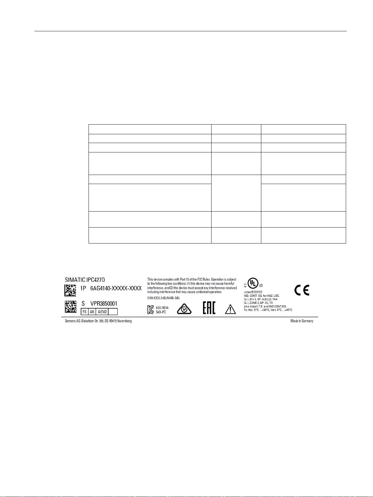
3.1.2
Identification data of the device
Unpacking the device
Identification date
Source
Value
Serial number
Nameplate
S VP ...
have COA labels
Ethernet address 1
menu
for PROFINET devices)
(only for PROFINET devices)
Nameplate
3.1 Preparing for installation
The device can be identified uniquely with the help of these numbers in case of repairs or
theft.
Enter identification data in the following table:
Article no. of the device Nameplate 6AG4140-...
Microsoft Windows Product Key
Certificate of Authenticity (COA)
Ethernet address 2 (not for PROFINET devices)
Back of the device
BIOS setup, "Advanced" -> "Peripheral
Configuration"
Only devices with preinstalled
Windows operating systems
CP 1616 onboard MAC Address Layer 2 (only
CP 1616 onboard MAC address PROFINET
SIMATIC IPC427D
Operating Instructions, 05/2017, A5E31347215-AB
29

Installing and connecting the device
Example of a COA label
See also
3.1 Preparing for installation
Microsoft Windows "Product Key" on the "Certificate of Authenticity" (COA):
The COA label is only attached to the rear of the device containing a Windows Embedded
Standard 7 or Windows 7 operating system.
● COA label of a device with Windows Embedded Standard 7 operating system
● COA label of a device with Windows 7 operating system
● COA label of a device with Windows 7 operating system with new safety feature
The silver scratch-off box is an additional safety feature to protect the product key from
unauthorized use by third parties. The silver scratch-off box partially hides the product
key. It is supposed to prevent use of the product key by unauthorized third parties. You
usually do not need this product key for commissioning because a valid product key has
already been integrated into the pre-installed operating system.
COA label with scratch-off box
(https://support.industry.siemens.com/cs/ww/de/view/109744977/en)
SIMATIC IPC427D
30 Operating Instructions, 05/2017, A5E31347215-AB
 Loading...