

Siemens SIMATIC IPC427C Operating Instructions Manual

SIMATIC Industrial PC SIMATIC IPC427C
_
_____________
_
_____________
_
_____________
_
_____________
_
_____________
_
_____________
_
_____________
_
_____________
_
_____________
_
_____________
_
_____________
_
_____________
_
_____________
_
_____________
_
_____________
_
_____________
_
_____________
_
_____________
_
_____________
Introduction
1
Safety Instructions
2
Description
3
Application planning
4
Installing/mounting
5
Connecting
6
Commissioning
7
Integration into an
Automation System
8
Functions
9
Expansions and
Configurations
10
Maintenance and Service
11
Alarm, error and system
messages
12
Troubleshooting/FAQs
13
Technical specifications
14
Dimension drawings
15
Detailed descriptions
16
Appendix
A
ESD guidelines
B
List of abbreviations
C
SIMATIC
Industrial PC
SIMATIC IPC427C
Operating Instructions
04/2009
A5E02414743-01
Legal information
Legal information
Warning notice system
This manual contains notices you have to observe in order to ensure your personal safety, as well as to prevent
damage to property. The notices referring to your personal safety are highlighted in the manual by a safety alert
symbol, notices referring only to property damage have no safety alert symbol. These notices shown below are
graded according to the degree of danger.
DANGER
indicates that death or severe personal injury will result if proper precautions are not taken.
WARNING
indicates that death or severe personal injury may result if proper precautions are not taken.
CAUTION
with a safety alert symbol, indicates that minor personal injury can result if proper precautions are not taken.
CAUTION
without a safety alert symbol, indicates that property damage can result if proper precautions are not taken.
NOTICE
indicates that an unintended result or situation can occur if the corresponding information is not taken into
account.
If more than one degree of danger is present, the warning notice representing the highest degree of danger will
be used. A notice warning of injury to persons with a safety alert symbol may also include a warning relating to
property damage.
Qualified Personnel
The device/system may only be set up and used in conjunction with this documentation. Commissioning and
operation of a device/system may only be performed by qualified personnel. Within the context of the safety notes
in this documentation qualified persons are defined as persons who are authorized to commission, ground and
label devices, systems and circuits in accordance with established safety practices and standards.
Proper use of Siemens products
Note the following:
WARNING
Siemens products may only be used for the applications described in the catalog and in the relevant technical
documentation. If products and components from other manufacturers are used, these must be recommended
or approved by Siemens. Proper transport, storage, installation, assembly, commissioning, operation and
maintenance are required to ensure that the products operate safely and without any problems. The permissible
ambient conditions must be adhered to. The information in the relevant documentation must be observed.
Trademarks
All names identified by ® are registered trademarks of the Siemens AG. The remaining trademarks in this
publication may be trademarks whose use by third parties for their own purposes could violate the rights of the
owner.
Disclaimer of Liability
We have reviewed the contents of this publication to ensure consistency with the hardware and software
described. Since variance cannot be precluded entirely, we cannot guarantee full consistency. However, the
information in this publication is reviewed regularly and any necessary corrections are included in subsequent
editions.
Siemens AG
Industry Sector
Postfach 48 48
90026 NÜRNBERG
GERMANY
A5E02414743-01
Ⓟ 04/2009
Copyright © Siemens AG 2009.
Technical data subject to change

SIMATIC IPC427C
Operating Instructions, 04/2009, A5E02414743-01
3
Table of contents
1 Introduction................................................................................................................................................
7
1.1 Preface...........................................................................................................................................
7
1.2 Guideline to the Operating Instructions .........................................................................................
8
2 Safety Instructions.....................................................................................................................................
9
2.1 General safety instructions ............................................................................................................
9
3 Description...............................................................................................................................................
11
3.1 Overview ......................................................................................................................................
11
3.2 Applications..................................................................................................................................
12
3.3 Features.......................................................................................................................................
13
3.4 Windows Embedded Standard 2009 ...........................................................................................
15
3.5 Design..........................................................................................................................................
17
3.5.1 External Design............................................................................................................................
17
3.5.2 Connection components ..............................................................................................................
18
3.5.3 Operator controls .........................................................................................................................
19
3.5.4 Status displays.............................................................................................................................
20
4 Application planning.................................................................................................................................
21
4.1 Transport......................................................................................................................................
21
4.2 Unpacking and checking the delivery unit ...................................................................................
22
4.3 Ambient and Environmental Conditions.......................................................................................
24
5 Installing/mounting...................................................................................................................................
25
5.1 Permitted mounting positions.......................................................................................................
25
5.2 Mounting information ...................................................................................................................
27
5.3 Mounting the device.....................................................................................................................
27
5.4 Mounting on DIN rails ..................................................................................................................
28
5.5 Mounting with mounting brackets ................................................................................................
30
5.6 Upright mounting..........................................................................................................................
32
6 Connecting ..............................................................................................................................................
33
6.1 Connecting peripheral equipment................................................................................................
33
6.2 Connecting the 24 V DC power supply........................................................................................
34
6.3 Protective ground connection ......................................................................................................
35
6.4 USB strain-relief...........................................................................................................................
36

Table of contents
SIMATIC IPC427C
4 Operating Instructions, 04/2009, A5E02414743-01
7 Commissioning ........................................................................................................................................ 37
7.1 Note before commissioning......................................................................................................... 37
7.2 Commissioning - Windows Embedded Standard 2009 .............................................................. 38
7.2.1 Basic commissioning - initial startup ........................................................................................... 38
7.3 Commissioning - Windows XP Professional............................................................................... 40
7.3.1 Basic commissioning - initial startup ........................................................................................... 40
7.3.2 Setting up the language selection for Windows XP Professional / Embedded Standard........... 41
7.4 Commissioning - other operating systems.................................................................................. 42
7.4.1 Commissioning - guide................................................................................................................ 42
8 Integration into an Automation System .................................................................................................... 43
8.1 Overview ..................................................................................................................................... 43
9 Functions................................................................................................................................................. 45
9.1 Monitoring Functions................................................................................................................... 45
9.1.1 Introduction ................................................................................................................................. 45
9.1.2 Temperature monitoring/display ................................................................................................. 46
9.1.3 Watchdog (WD)........................................................................................................................... 47
9.2 Enhanced Write Filter (EWF) ...................................................................................................... 48
9.3 File Based Write Filter (FBWF) ................................................................................................... 50
9.4 SRAM buffer memory.................................................................................................................. 52
9.5 Battery monitoring ....................................................................................................................... 53
9.6 Operation without monitor and keyboard.................................................................................... 54
10 Expansions and Configurations ............................................................................................................... 55
10.1 Open the device (front panel) ..................................................................................................... 55
10.2 Memory expansion ...................................................................................................................... 57
10.2.1 Installing the memory module ..................................................................................................... 57
10.3 Installing PCI-104 / PC/104 Plus modules .................................................................................. 59
10.3.1 Notes on the modules ................................................................................................................. 59
10.3.2 Mounting PCI-104 or PC/104 Plus modules ............................................................................... 60
10.4 Installing/Removing Compact Flash Cards................................................................................. 62
10.4.1 Installation options for Compact Flash cards.............................................................................. 62
10.4.2 Installing/removing an accessible Compact Flash card.............................................................. 63
10.4.3 Installing/removing a built-in Compact Flash card ...................................................................... 66
11 Maintenance and Service ........................................................................................................................ 67
11.1 Removing and Installing Hardware Components........................................................................ 67
11.1.1 Repairs........................................................................................................................................ 67
11.1.2 Preventive maintenance.............................................................................................................. 68
11.1.3 Replacing hard disk or SSD drive ............................................................................................... 69
11.1.4 Replace the backup battery ........................................................................................................ 71
11.2 Reinstalling the operating system ............................................................................................... 73
11.2.1 Windows Embedded Standard 2009 .......................................................................................... 73
11.2.1.1 General installation procedure .................................................................................................... 73
11.2.1.2 Restoring the software to factory state using the Restore DVD ................................................. 74
11.2.2 Windows XP Professional........................................................................................................... 76
11.2.2.1 General installation procedure .................................................................................................... 76

Table of contents
SIMATIC IPC427C
Operating Instructions, 04/2009, A5E02414743-01
5
11.2.2.2 Restoring the Software to Factory State Using the Restore DVD ...............................................77
11.2.2.3 Setting up the operating system via the Recovery CD/DVD .......................................................
79
11.3 Partitioning data media ................................................................................................................
81
11.3.1 Setting up the partitions under Windows Embedded Standard 2009..........................................
81
11.3.2 Setting up the partitions under Windows XP Professional ..........................................................
82
11.4 Installing drivers and software .....................................................................................................
83
11.4.1 Driver installation under Windows Embedded Standard 2009 ....................................................
83
11.4.2 Installing drivers and software .....................................................................................................
83
11.5 Installing updates .........................................................................................................................
84
11.5.1 Updating the operating system ....................................................................................................
84
11.5.2 Installing or updating application programs and drivers ..............................................................
84
11.5.3 Performing a BIOS update...........................................................................................................
85
11.6 Data backup .................................................................................................................................
86
11.6.1 Creating an image........................................................................................................................
86
12 Alarm, error and system messages .........................................................................................................
87
12.1 Boot error messages....................................................................................................................
87
13 Troubleshooting/FAQs.............................................................................................................................
89
13.1 General problems ........................................................................................................................
89
13.2 Problems when using modules of third-party manufacturers ......................................................
90
14 Technical specifications...........................................................................................................................
91
14.1 General specifications..................................................................................................................
91
14.2 Power requirements of the components ......................................................................................
95
14.3 Integrated DC power supply ........................................................................................................
96
15 Dimension drawings ................................................................................................................................
97
15.1 Overview of the dimensional drawings ........................................................................................
97
15.2 Dimension drawings of the device ...............................................................................................
98
15.3 Dimension drawings of the device with mounting brackets .........................................................
99
15.4 Dimensional drawings of the device with vertical mounting angles...........................................
101
15.5 Dimensional drawings of the device with expansion frames .....................................................
102
15.6 Dimension drawing of the blanking plate ...................................................................................
103
16 Detailed descriptions .............................................................................................................................
105
16.1 Internal components ..................................................................................................................
105
16.1.1 Overview of internal components...............................................................................................
105
16.1.2 Technical features of the motherboard ......................................................................................
106
16.1.3 External ports.............................................................................................................................
107
16.1.3.1 Overview ....................................................................................................................................
107
16.1.3.2 COM1/2......................................................................................................................................
107
16.1.3.3 DVI-I...........................................................................................................................................
108
16.1.3.4 Ethernet......................................................................................................................................
109
16.1.3.5 USB............................................................................................................................................
109
16.1.3.6 PROFIBUS.................................................................................................................................
110
16.1.3.7 CAN bus.....................................................................................................................................
110
16.1.4 Internal ports ..............................................................................................................................
111
16.1.4.1 Overview ....................................................................................................................................
111

Table of contents
SIMATIC IPC427C
6 Operating Instructions, 04/2009, A5E02414743-01
16.1.4.2 Compact Flash card interface ................................................................................................... 111
16.1.4.3 PCI-104 or PC/104-Plus interface (PCI part)............................................................................ 112
16.2 BIOS Setup ............................................................................................................................... 113
16.2.1 Overview ................................................................................................................................... 113
16.2.2 Starting BIOS Setup.................................................................................................................. 114
16.2.3 BIOS Setup menus ................................................................................................................... 115
16.2.4 Main menu................................................................................................................................. 117
16.2.5 Advanced Menu ........................................................................................................................ 122
16.2.6 Security menu ........................................................................................................................... 125
16.2.7 Boot menu................................................................................................................................. 126
16.2.8 Version menu ............................................................................................................................ 130
16.2.9 Exit Menu .................................................................................................................................. 131
16.2.10 Default BIOS Setup entries....................................................................................................... 132
16.3 System resources ..................................................................................................................... 135
16.3.1 Currently allocated system resources....................................................................................... 135
16.3.2 System resources used by the BIOS/DOS ............................................................................... 136
16.3.2.1 PCI Interrupt Lines .................................................................................................................... 136
16.4 I/O Address Areas..................................................................................................................... 137
16.4.1 Overview of the internal module registers................................................................................. 137
16.4.2 Watchdog enable register / 066h select register (read/write, address 062h) ........................... 138
16.4.3 Watchdog trigger register (read only, address 066h) ............................................................... 138
16.4.4 CAN base address register (write only, address 066h) ............................................................ 139
16.4.5 Output register LED 1 / 2 (read/write, address 404Eh)............................................................. 140
16.4.6 Battery status tab (read-only, address 50Fh)............................................................................ 141
16.4.7 SRAM address register............................................................................................................. 142
A Appendix................................................................................................................................................ 143
A.1 Guidelines and declarations...................................................................................................... 143
A.2 Certificates and approvals......................................................................................................... 144
A.3 Service and support .................................................................................................................. 146
B ESD guidelines ...................................................................................................................................... 147
B.1 ESD Guidelines............................................................................................................
............. 147
C List of abbreviations............................................................................................................................... 149
C.1 Abbreviations ............................................................................................................................ 149
Glossary ................................................................................................................................................ 155
Index...................................................................................................................................................... 167

SIMATIC IPC427C
Operating Instructions, 04/2009, A5E02414743-01
7
Introduction
1
1.1 Preface
Objective of this documentation
These operating instructions contain all the information you need for commissioning and
operation of the SIMATIC IPC427C.
It is intended both for programming and testing personnel who commission the device and
connect it with other units (automation systems, programming devices), as well as for service
and maintenance personnel who install add-ons or carry out fault/error analyses.
Basic knowledge requirements
A solid background in personal computers and Microsoft operating systems is required to
understand this manual. General knowledge in the field automation control engineering is
recommended.
Scope of validity of this document
The operating instructions are valid for all supplied variations of the SIMATIC IPC427C and
describe the delivery status as of May 2009.
Position in the information landscape
The documentation for the SIMATIC IPC427C includes the following sections:
● SIMATIC IPC427C, Operating Instructions (Compact)
● SIMATIC IPC427C, Operating Instructions
The documentation is supplied in German and English with the device in electronic form as a
PDF file on the "Documentation and Drivers" DVD.
Conventions
The term "PC" or "device" is sometimes used to refer to the SIMATIC IPC427C product in
this documentation.
History
Currently released versions of this operating manual:
Edition Comment
04/2009 First edition

Introduction
1.2 Guideline to the Operating Instructions
SIMATIC IPC427C
8 Operating Instructions, 04/2009, A5E02414743-01
1.2 Guideline to the Operating Instructions
Contents format Table of Contents
Contents Organization of the documentation, including the index of pages and chapters
Introduction Purpose, layout and description of the important topics.
Safety instructions Refers to all the valid technical safety aspects which have to be adhered to while installing,
commissioning and operating the product/systemin and in reference to statutory
regulations.
Description Fields of application, the features and the structure of the product/system
Application planning Aspects of storage, transport, environmental and EMC conditions to be considered in the
preparatory stage
Mounting Product installation options and installation instructions
Connecting Options of connecting the product and connection instructions
Commissioning Commissioning the product/system.
Integration Options of integrating the product into existing or planned system environments/networks
Functions Monitoring and display functions
Expansions / configurations Procedure for installing expansion devices (memory, modules).
Maintenance and service Replacement of hardware components, restoring and setup of the operating system,
installation of drivers and software
Alarm, error and system
messages
Error messages from booting
Troubleshooting Problems, cause, remedy
Technical specifications General specifications in compliance with relevant standards and current/voltage values
Dimension drawings Dimensions of the device and of modules
Detailed descriptions Structure, function and features of vital components, distribution of system resources and
use of the BIOS Setup routine
Appendix Guidelines and certifications, service and support, notes on retrofitting.
ESD guidelines General ESD guidelines.

SIMATIC IPC427C
Operating Instructions, 04/2009, A5E02414743-01
9
Safety Instructions
2
2.1 General safety instructions
CAUTION
Please observe the safety instructions on the back of the cover sheet of this
documentation. You should not expand your device unless you have read the relevant
safety instructions.
This device is compliant with the relevant safety measures to IEC, EN, VDE, UL, and CSA. If
you have questions about the validity of the installation in the planned environment, please
contact your service representative.
Repairs
Only authorized personnel are permitted to repair the device.
WARNING
Unauthorized opening of and improper repairs to the device may result in substantial
damage to equipment or endanger the user.
System expansions
Only install system expansion devices designed for this device. The installation of other
expansions can damage the system and violate the radio-interference suppression
regulations. Contact your technical support team or where you purchased your PC to find out
which system expansion devices may safely be installed.
CAUTION
If you install or exchange system expansions and damage your device, the warranty
becomes void.
Safety Instructions
2.1 General safety instructions
SIMATIC IPC427C
10 Operating Instructions, 04/2009, A5E02414743-01
Battery
This device is equipped with a Lithium battery. Batteries may only be replaced by qualified
personnel.
CAUTION
There is the risk of an explosion if the battery is not replaced as directed. Replace the
battery only with the same type or with an equivalent type recommended by the
manufacturer. Dispose of used batteries in accordance with local regulations.
WARNING
Risk of explosion and release of harmful substances!
For this reason, do not burn lithium batteries, do not solder on the cell body, do not open,
do not short circuit, do not reverse polarity, do not heat above 100°C, dispose of correctly,
and protect against direct sunlight, dampness and dew.
ESD directives
Modules containing electrostatic sensitive devices (ESDs) can be identified by the following
label:
Strictly follow the guidelines mentioned below when handling modules which are sensitive to
ESD:
● Always discharge your body´s static electricity before handling modules that are sensitive
to ESD (for example, by touching a grounded object).
● All devices and tools must be free of static charge.
● Always pull the mains connector and disconnect the battery before installing or removing
modules which are sensitive to ESD.
● Handle modules fitted with ESDs only by their edges.
● Do not touch any connector pins or conductors on modules containing ESDs.
SIMATIC IPC427C
Operating Instructions, 04/2009, A5E02414743-01
11
Description
3
3.1 Overview
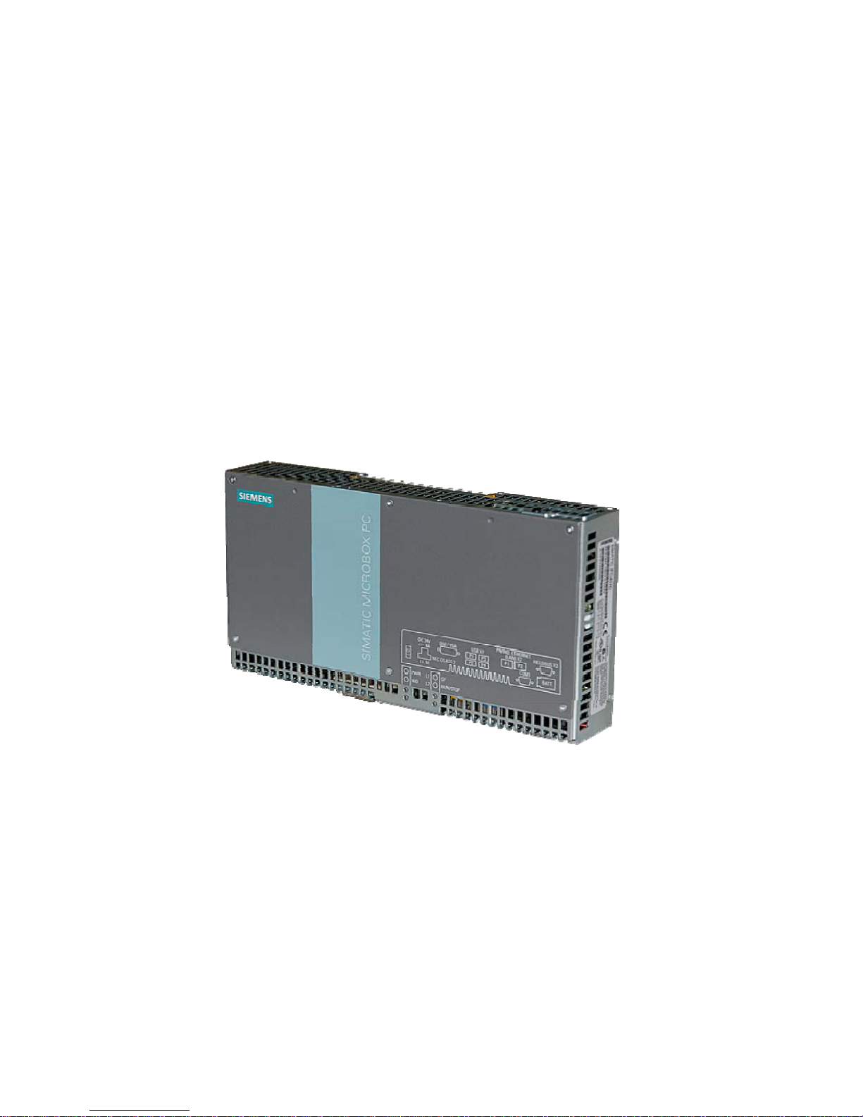
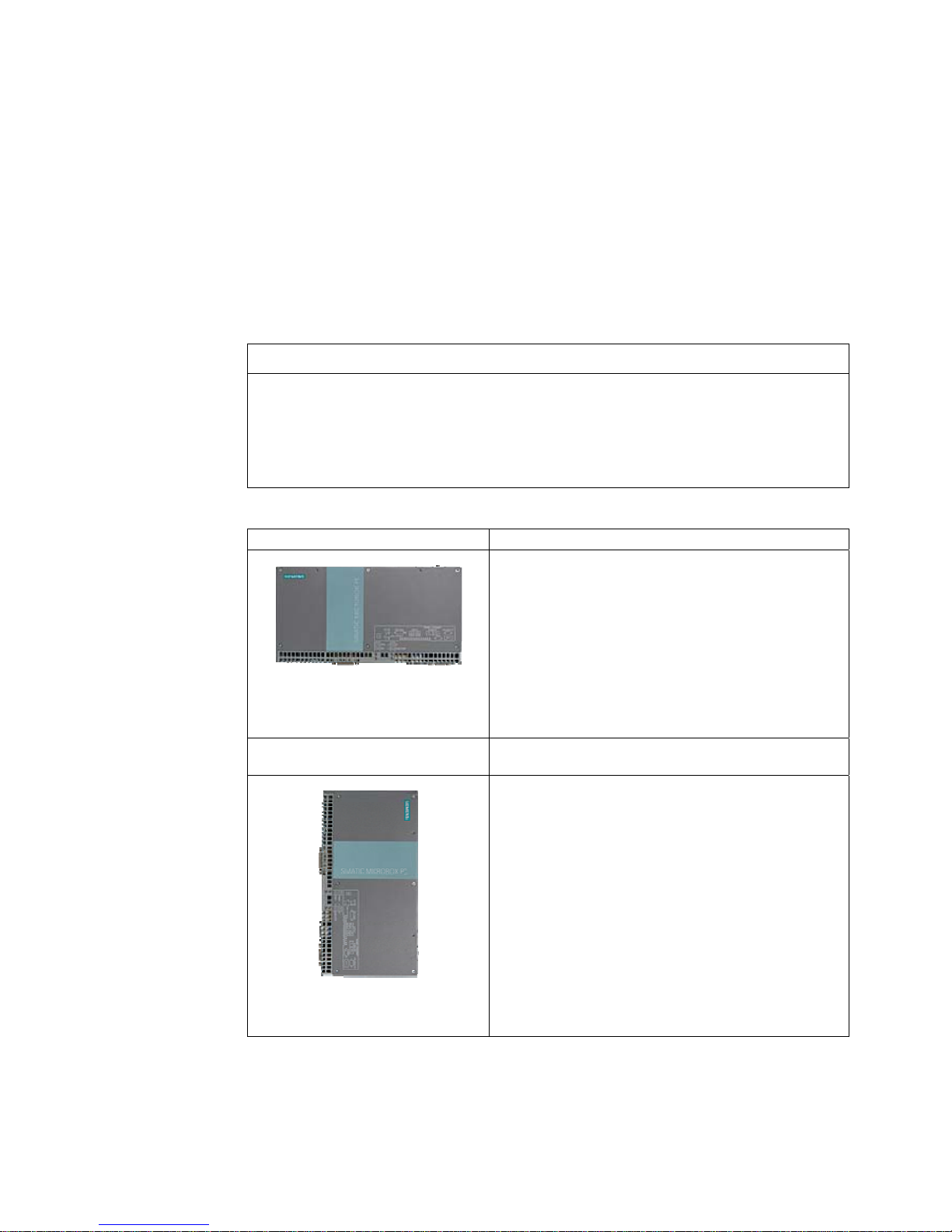
The SIMATIC IPC427C provides high-level industrial performance.
● Compact design
● Maintenance-free operation
● High degree of ruggedness
Figure 3-1 SIMATIC IPC427C

Description
3.2 Applications
SIMATIC IPC427C
12 Operating Instructions, 04/2009, A5E02414743-01
3.2 Applications
The device provides industrial PC systems for high-performance and space-saving
applications in particular in the field of machine, systems and switchgear cabinet
engineering:
● Measuring and controlling of process and machine data (for example, automated washing
systems, assembling machines, packaging machines)
● Operating and visualization tasks with separate display / monitor solutions (information
terminals, large-scale displays in automotive production)
● Data logging and processing (for example, system data logging, distributed process
control)

Description
3.3 Features
SIMATIC IPC427C
Operating Instructions, 04/2009, A5E02414743-01
13
3.3 Features
Basic data
Installation / mounting
• Installation on a DIN rail
• Wall mounting
• Vertical mountin
• Hanging assembly
Processor
• Intel Celeron M 1.2 GHz, 800 MHz FSB, 1 MB SLC or
• Intel Pentium Core 2 Solo 1.2 GHz, 800 MHz FSB,
3 MB SLC or
• Intel Pentium Core 2 Duo 1.2 GHz, 800 MHz FSB,
3 MB SLC
Main memory
• 512 MB DDR3-SDRAM SODIMM
• 1 GB DDR3-SDRAM SODIMM
• 2 GB DDR3-SDRAM SODIMM
• 4 GB DDR3-SDRAM SODIMM
Free slots for expansion Up to 3 x PCI/104 modules or 3x PC/104-
Plus
module
(PCI bus only);
installed with expansion frame
Graphics
• Integrated Intel GMA4500 graphics
• CRT resolution of 640x480 pixels up to 1920x1200
pixels
• DVI resolution of 640x480 pixels up to 1920x1200
pixels
• 8-512 MB graphics memory taken from main memory
(dynamic UMA)
Power supply 24 VDC (19.2 – 28.8 V) max. 4 A
Conditions of use
• Operation without fan
Drives and storage media
Compact Flash card
• 256 MByte optional or
• 2 GB optional or
• 4 GB optional or
• 8 GB optional
Hard disk ≥ 80 GB SATA HD 2.5" optional
SSD (Solid State Disk) ≥ 32 GB optional
Floppy/CDROM drive Connected via external USB port
USB stick Connected via external USB port

Description
3.3 Features
SIMATIC IPC427C
14 Operating Instructions, 04/2009, A5E02414743-01
Basic data
Ports
Serial COM1 (RS232)
COM2 (RS232); optional
Graphics DVI-I: combined DVI and VGA
USB 4 x USB 2.0 high current
Ethernet 2 x RJ 45 (10/100/1000 Mbps)
PROFIBUS DP 12 Mbps (isolated potential,
compatible to CP 5611), optional
CAN interface Optional
Keyboard, mouse Connected via external USB port
Monitoring and safety functions
Temperature
• When permitted temperature range is exceeded
• Warnings can be analyzed by application program
(local, via LAN)
Watchdog
• Monitoring function for program execution
• Restart can be parameterized in the event of a fault
• Warnings can be analyzed by application program
(local, via LAN)
LED display 4 LEDs for displaying system status
2 of these can be programmed by the user1
Transient voltage interruption Up to 15 ms buffer time at full load
Buffer memory 2 MB battery-buffered SRAM1
Software
Operating systems
Available
• Without
• Windows Embedded Standard 2009
• Windows XP Professional MUI SP3 preinstalled
2
Project-specific
• LINUX
• QNX
• VxWorks
• Others on request
• RMOS3 V3.40 (ordered separately)
1
You can find additional information about addressing the LEDs or the SRAM under a
Windows operating system in the section "Output register LED L1/L2". You can find example
programs for addressing the LEDs under Windows XP and under RMOS3 under the FAQ at
the Customer Support site Industry Automation and Drive Technologies - Homepage
(
http://www.siemens.com/automation/service&support).
2
MUI: Multi Language User Interface; 5 languages (English, German, French, Spanish,
Italian)

Description
3.4 Windows Embedded Standard 2009
SIMATIC IPC427C
Operating Instructions, 04/2009, A5E02414743-01
15
3.4 Windows Embedded Standard 2009
The supplied Windows Embedded Standard has the product version 2009. The overview
shows the basic device functions under Windows Embedded Standard 2009:
Function Hard disk / SSD version Compact Flash card version
Enhanced Write Filter (EWF) In RAM RAM(REG) In RAM RAM(REG)
SIMATIC IPC DiagBase Available V 1.2 Available V 1.2
Pagefile Deactivated in favor of the
EWF
Deactivated in favor of the EWF
System Restore Core Available Available
File based Writefilter (FBWF) Available Available
Registryfilter Available Available
Device Update Agent (DUA) Available Available
HORM Available Available
Telnet Server Available Available
Windows Backup Available Available
User Mode Driver Framework
(UMDF)
Available Available
MUI GER/FRA/ITA/SPA
Default language: English
GER
default language: English
Administrator Account Available Available
User Account Available Available
Explorer Shell Available Available
Internet Explorer (IE) Available, IE7 Available, IE7
Internet Information Server (IIS) Available V 5.1 Available V 5.1
Terminal Services Available Available
Bluetooth Available Available
Wireless Network Support Available Available
Windows Firewall Available Available
Windows Security Center Available Available
MSN Explorer Available Not available
Outlook Express Available Available
Administrative Tools Available Available
SMS Advanced Client Available Not available
Remote Desktop Available V 6.0 Available V 6.0
Remote Assistance Available Available
.NET Framework Available, V3.5 Not available
ASP.NET Available, V3.5 Not available
Windows .NET Messenger Available V 4.7 Available V 4.7
Code pages/User
Location/Keyboard
Available Selection available
Disk Management Services Available Available
Windows Installer Service Available V 3.1 Available V 3.1
Class Installer Available Available

Description
3.4 Windows Embedded Standard 2009
SIMATIC IPC427C
16 Operating Instructions, 04/2009, A5E02414743-01
Function Hard disk / SSD version Compact Flash card version
CoDevice Installer Available Available
Windows Movie Maker Available V 2.1 Not available
Media Player Available, V11.0 Available, V11.0
Windows Media Player Tour Available Not available
DirectX V9.0c V9.0c
Accessories Available Available
Help files for all components Available Not available
Games Available Not available
Fonts 316 118
Windows XP Tour Available Not available
Microsoft Silverlight Available V 1.0 Available V 1.0
NetMeeting Available V 3.1 Available V 3.1
Note
Activation of "HORM" and creation of a "Hiber File"
When "HORM" is activated, the "Hibernate" function can be used for Windows Embedded
Standard 2009:
• EWFMGR C: /activatehorm
"Hibernate" is activated following a restart. The system then always boots from this file.
Description
3.5 Design
SIMATIC IPC427C
Operating Instructions, 04/2009, A5E02414743-01
17
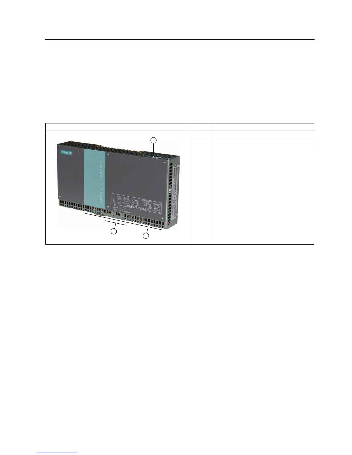
3.5 Design
3.5.1 External Design
Device components Pos Description
① Cover plate for Compact Flash module
② Connection elements
③ Status displays
Description
3.5 Design
SIMATIC IPC427C
18 Operating Instructions, 04/2009, A5E02414743-01
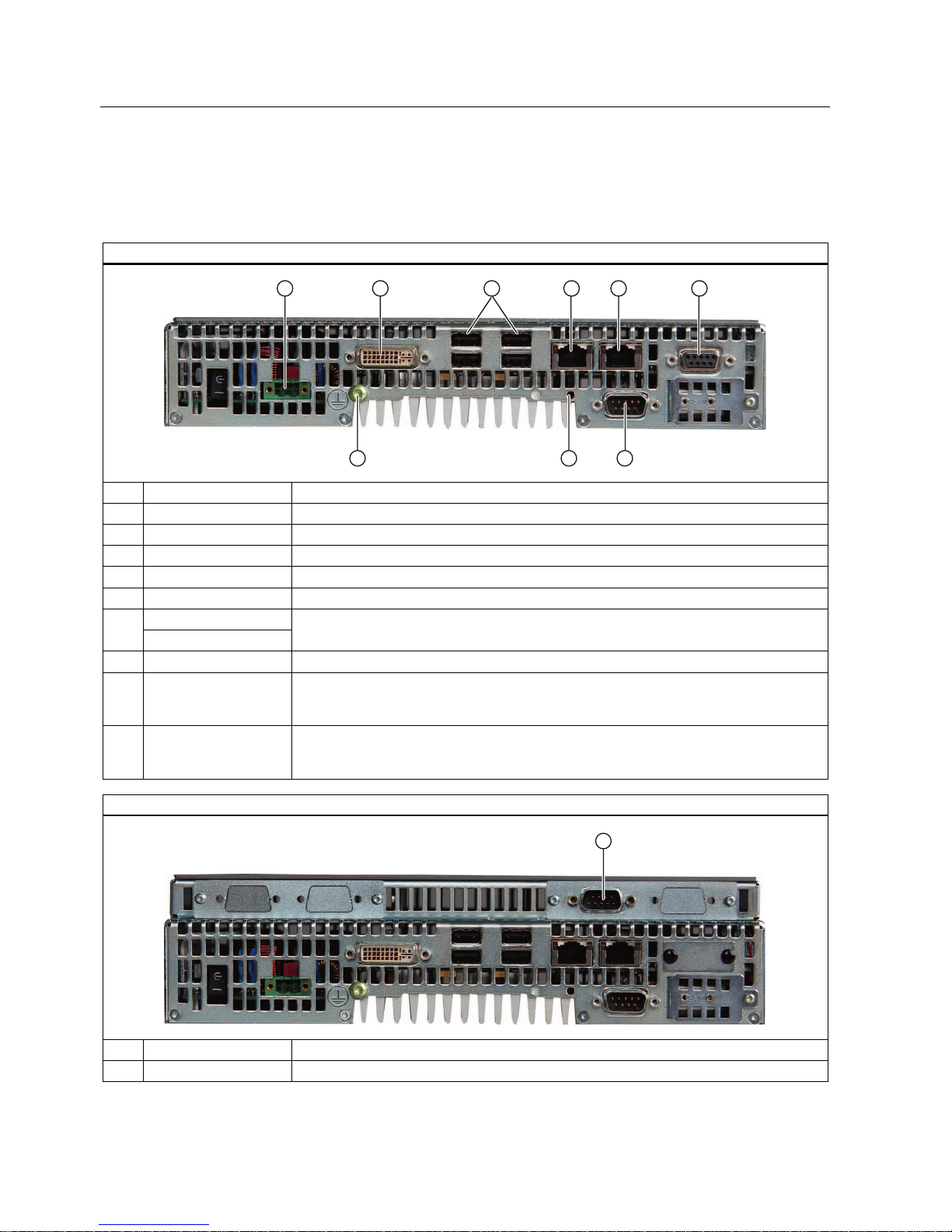
3.5.2 Connection components
Ports and power supply
Location of connection elements (version with PROFIBUS or CAN)
Pos Name Description
① 24 VDC Connection for a 24 V DC power supply
② DVI/VGA DVI/VGA connection for CRT or LCD monitor with DVI interface
③ USB 4 USB 2.0 connections, high-speed / low current
④ PN/IND. ETHERNET RJ45 Ethernet connection 1 (exclusive PCI interrupt) for 10/100/1000 Mbps
⑤ PN/IND. ETHERNET RJ45 Ethernet connection 2 (shared PCI interrupt) for 10/100/1000 Mbps
PROFIBUS DP/MPI ⑥
CAN fieldbus
PROFIBUS DP/MPI interface (RS 485 isolated), 9-pin Cannon socket or CAN fieldbus
(on request)
⑦ COM1 Serial port (RS232) 9-pin Cannon connector
⑧ USB strain-relief
fastener
The USB strain relief must be fastened to the device enclosure with an oval-head screw
(M4 thread). The USB cables can be fastened to the strain-relief assembly with a cable
tie.
⑨ PE terminal The PE terminal (M4 thread) must be connected to the protective ground conductor of the
plant, in which the device is to be installed. The minimum conductor cross-section may not
be less than 2,5 mm2.
Location of the connection elements (second COM interface)
Pos Designation Description
① COM2 Serial port (RS232) 9-pin Cannon connector
Description
3.5 Design
SIMATIC IPC427C
Operating Instructions, 04/2009, A5E02414743-01
19
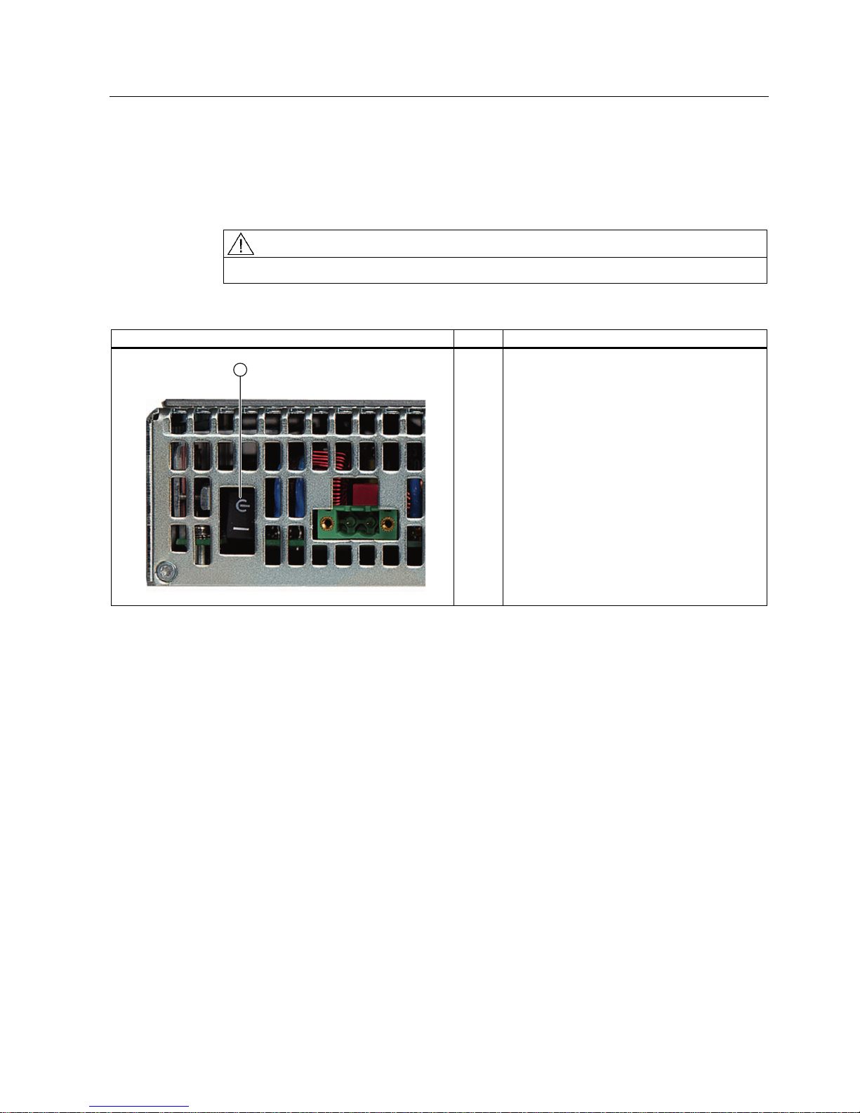
3.5.3 Operator controls
On/Off switch
CAUTION
The On/Off switch does not disconnect the device from the supply voltage.
Position of on/off switch Pos Description
① The on/off switch turns off the output voltages of
the power supply but not disconnect from the
supply system.
The delivery condition is: Power switch turned
off.
Description
3.5 Design
SIMATIC IPC427C
20 Operating Instructions, 04/2009, A5E02414743-01
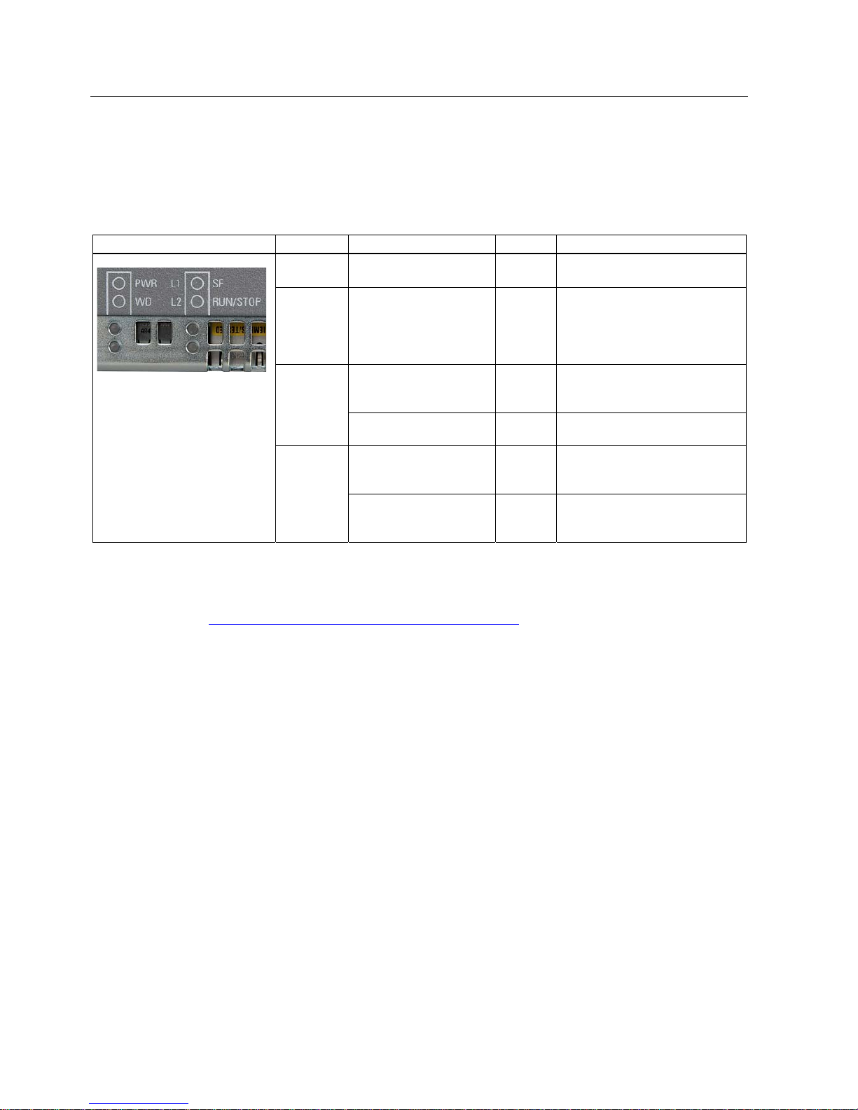
3.5.4 Status displays
Status displays LED Meaning LED Description
PWR Power supply OFF
GREEN
Standby mode
Supply voltage available
WD Watchdog status display OFF
GREEN
RED
Watchdog disabled Watchdog
enabled, monitoring time not
expired
Watchdog enabled, monitoring
time expired
User LED L1 OFF
YELLOW
RED
Can be controlled by user
programs1
L1
SF
Group errors RED Can be controlled by controller
program (e.g. WinAC)
1
User LED L2 OFF
YELLOW
GREEN
Can be controlled by user
programs1
L2
RUN/STOP
RUN
STOP
GREEN
YELLOW
Can be controlled by controller
program (e.g. WinAC)
1
1
You can find additional information about addressing the LEDs or the SRAM under a
Windows operating system in the section "Output register LED L1/L2". Example programs
for addressing the LEDs under Windows XP and under RMOS are available under the FAQ
at the Customer Support site Industry Automation and Drive Technologies - Homepage
(
http://www.siemens.com/automation/service&support).

SIMATIC IPC427C
Operating Instructions, 04/2009, A5E02414743-01
21
Application planning
4
4.1 Transport
Despite the device's rugged design, its internal components are sensitive to severe
vibrations or shock. You must therefore protect the device from severe mechanical stress
when transporting it.
You should always use the original packaging for shipping and transporting the device.
CAUTION
Risk of damage to the device!
If you are transporting the device in extreme weather conditions with large fluctuations in
temperature, care must be take to ensure that no moisture forms on or in the device
(condensation).
If condensation has developed on the device, wait at least 12 hours before you switch it on.
Application planning
4.2 Unpacking and checking the delivery unit
SIMATIC IPC427C
22 Operating Instructions, 04/2009, A5E02414743-01
4.2 Unpacking and checking the delivery unit
Unpacking the device
Note the following when unpacking the unit:
● It is advisable not to dispose of the original packing material. Keep it in case you have to
transport the unit again.
● Please keep the documentation in a safe place. It is required for initial commissioning and
is part of the device.
● Check the delivery unit for any visible transport damage.
● Verify that the shipment contains the complete unit and your separately ordered
accessories. Please inform your local dealer of any disagreements or transport damages.
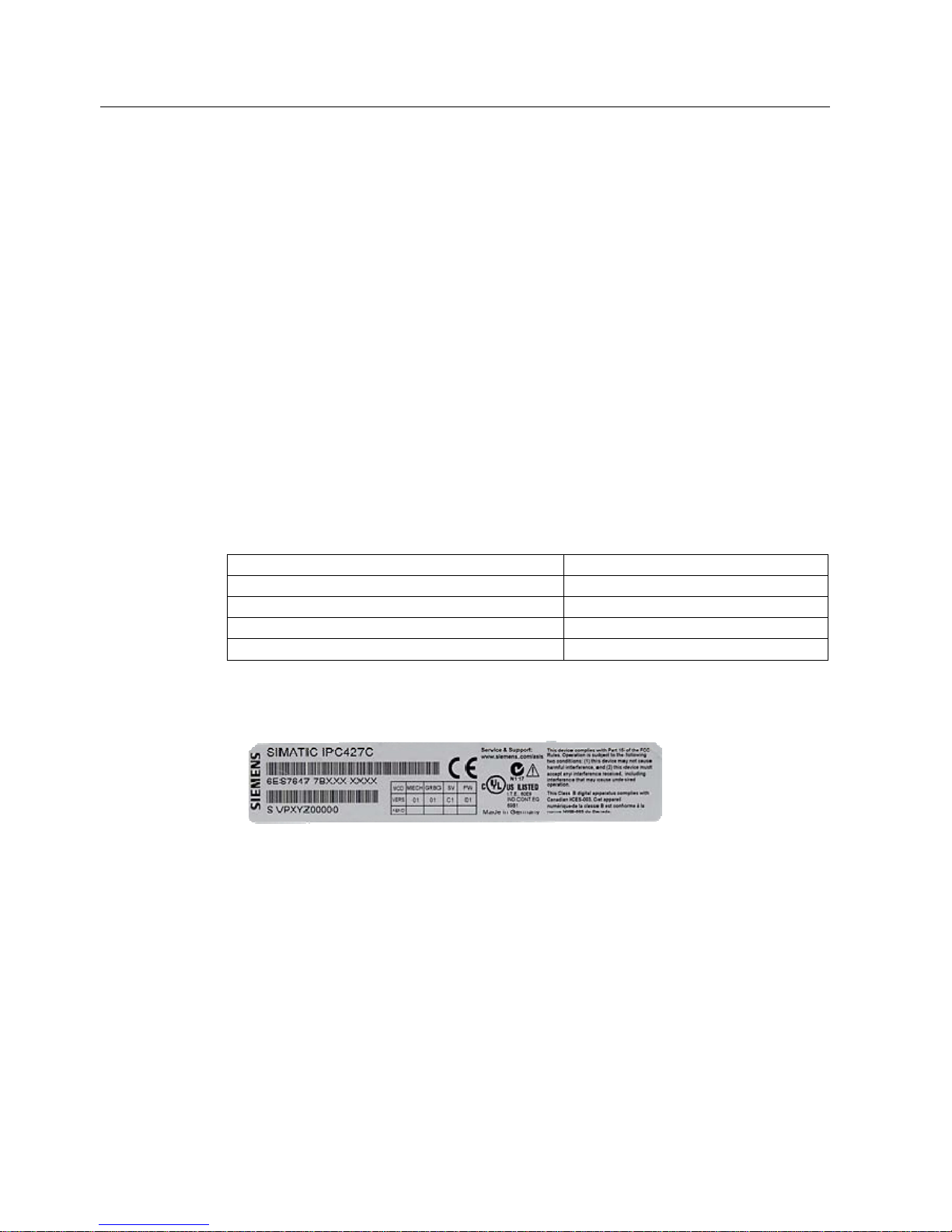
Noting the device identification data
The device can be identified uniquely with the help of these numbers in case of repairs or
theft.
Enter the data in the following table:
Serial number S VP ...
Order number of the device 6ES 7647-7B ...
Microsoft Windows Product Key
Ethernet address 1
Ethernet address 2
You can find the corresponding data here:
● Serial number: The serial number is available on the rating plate on the right side of the
device.
● Order number of the device: The order number is located on the rating plate.
Application planning
4.2 Unpacking and checking the delivery unit
SIMATIC IPC427C
Operating Instructions, 04/2009, A5E02414743-01
23
● Ethernet address: The Ethernet address of the device is available in your BIOS Setup
(F2 function key) under Main > Hardware Options > Ethernet 1 Address or
Ethernet 2 Address.
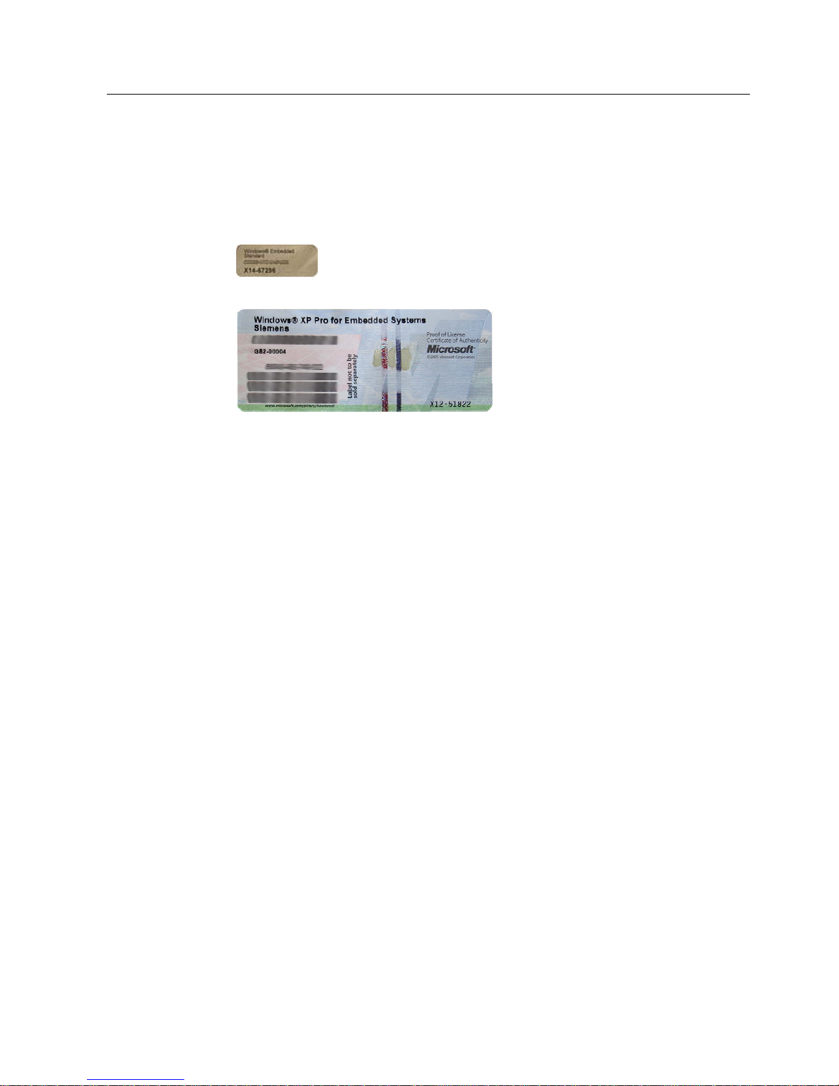
● Microsoft Windows "Product Key" from the "Certificate of Authenticity" (COA): The COA
label is only present in pre-installed Windows Embedded Standard 2009 or
XP Professional and is affixed to the back of the device.
Figure 4-1 COA Label Windows Embedded Standard 2009
Figure 4-2 COA Label Windows XP Pro for Embedded Systems

Application planning
4.3 Ambient and Environmental Conditions
SIMATIC IPC427C
24 Operating Instructions, 04/2009, A5E02414743-01
4.3 Ambient and Environmental Conditions
When you plan your project, you should make allowances for:
● The climatic and mechanical environmental conditions specified in the specifications
given in your operating instructions.
● The device is approved for operation in closed rooms only.
● Avoid extreme ambient conditions. Protect the device against dust, moisture and heat.
● Do not place the device in direct sunlight.
● Ensure that the distance to other components or the sides of cabinets is at least 50 mm
above and 100 mm below the device.
● Do not cover the ventilation slots of the device.
● Always observe the mounting positions permitted for this device.
● The connected or built-in peripherals should not introduce a counter emf in excess of
0.5 V into the device.
SIMATIC IPC427C
Operating Instructions, 04/2009, A5E02414743-01
25
Installing/mounting
5
5.1 Permitted mounting positions
NOTICE
The device is approved for operation in closed rooms only.
Ensure that there is a minimum clearance to the other components or the walls of a
housing:
• Below at least 100 mm
• Above at least 50 mm
Horizontal (preferred position) Permitted temperatures
Operation with hard disk:
• with up to 3 expansion modules
(max. load 9 W): +5 to +40°C
Operation with CompactFlash card and/or SSD drive:
• with up to 3 expansion modules
(max. load 9 W): 0 to +45°C
• with up to 3 expansion modules
(max. load 9 W) in RAL: 0 to +50°C
Operation with Compact Flash cards:
• without expansion modules in RAL: 0 to +55°C
Vertical
(power supply at the top)
Operation with hard disk:
• with up to 3 expansion modules
(max. load 9 W): +5 to +40°C
With installed Compact Flash card:
• without expansion modules: 0 to +45°C
Operation with CompactFlash card and/or SSD drive:
• with up to 3 expansion modules
(max. load 9 W) in RAL: 0 to +45°C
Operation with Compact Flash cards:
• with up to 3 expansion modules
(max. load 9 W) in RAL: 0 to +50°C
Notes:
When mounted on a DIN rail, the device should be secured
to prevent shifting (e.g. with a DIN rail ground terminal).
Installing/mounting
5.1 Permitted mounting positions
SIMATIC IPC427C
26 Operating Instructions, 04/2009, A5E02414743-01
Suspended
Operation with CompactFlash card and/or SSD drive and
without expansion modules:
0 to +40°C
Note:
Mounting brackets are required if the device is suspended.
Upright mounting Permitted temperatures
Operation with hard disk:
• with up to 3 expansion modules
(max. load 9 W): +5 to +40°C
With installed Compact Flash card:
• without expansion modules: 0 to +45°C
Operation with CompactFlash card and/or SSD drive:
• with up to 3 expansion modules
(max. load 9 W) in RAL: 0 to +45°C
Operation with Compact Flash cards:
• with up to 3 expansion modules
(max. load 9 W) in RAL: 0 to +50°C
RAL = Restricted Access Location
(e.g. installation of the unit in a lockable cabinet)
NOTICE
The safety and installation instructions for the expansion modules should be followed if the
device is expanded with PCI-104 / PC/104-plus modules.
If necessary, the device should be installed in an enclosure that meets the requirements of
paragraphs 4.6 and 4.7.3 of IEC/UL/EN/DINEN60950-1.

Installing/mounting
5.2 Mounting information
SIMATIC IPC427C
Operating Instructions, 04/2009, A5E02414743-01
27
5.2 Mounting information
Before you install the device, read the following mounting instructions.
NOTICE
Adhere to the SIMATIC assembly guidelines and the relevant DIN/VDE requirements or the
country-specific regulations when mounting in switching cabinets.
NOTICE
Ensure that the device is classified as "Open Type" when using the device in the area of
Industrial Control Equipment (UL508). A UL508 conform enclosure is therefore a
mandatory requirement for approval or operation according to UL508.
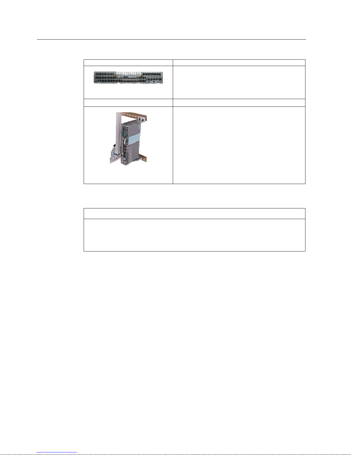
5.3 Mounting the device
Mounting methods
SIMATIC IPC427C can be mounted on DIN rails, with mounting brackets and in an upright
position.
Installing/mounting
5.4 Mounting on DIN rails
SIMATIC IPC427C
28 Operating Instructions, 04/2009, A5E02414743-01
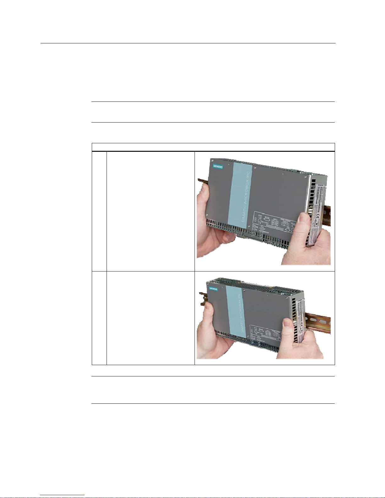
5.4 Mounting on DIN rails
Mounting the device on DIN rails
Note
Use of Siemens 35 mm standard mounting rail is recommended.
Steps for mounting on DIN rails
1. Set the device inclined on the
upper DIN rail.
2. Swing the device fully onto the rails
until both clamps completely latch.
Note
To ensure secure mounting on vertical mounting rails, a DIN rail ground terminal should be
mounted beneath the device.

Installing/mounting
5.4 Mounting on DIN rails
SIMATIC IPC427C
Operating Instructions, 04/2009, A5E02414743-01
29
NOTICE
The rails are secured to a wall or cabinet similar to mounting with mounting brackets.
Ensure that the wall or ceiling can hold four times the total weight of the device (including
the rails and additional expansion modules). Also see section
Mounting with mounting
brackets (Page
30).
Removing the device from the DIN rail
● Push down the device until the clamps release it.
● Swing the device out of the rails.
Installing/mounting
5.5 Mounting with mounting brackets
SIMATIC IPC427C
30 Operating Instructions, 04/2009, A5E02414743-01
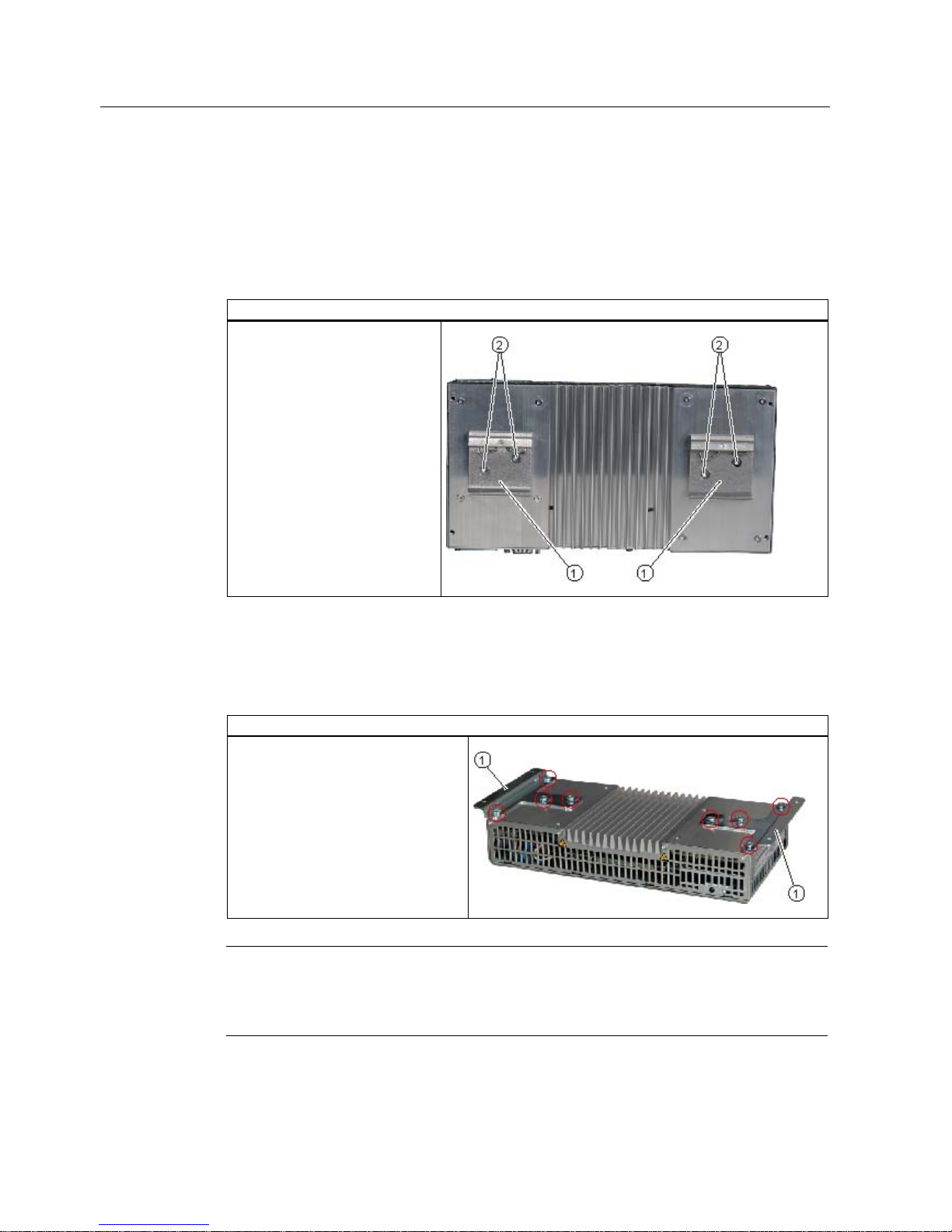
5.5 Mounting with mounting brackets
Removing mounting clamps from the device
Two mounting clamps are factory installed on the device for DIN rail mounting. These need
to be removed before mounting the mounting brackets.
Steps for removing the mounting clamps
Remove the four screws ② and
the two mounting clamps ① from
the back of the device.
Installing brackets on the device
Two mounting brackets are included in the device package. They can be installed on the
device with four screws supplied.
Steps for installing the mounting brackets
Install the mounting brackets on the
device.
Note
Required tools
You need a TORX T20 screwdriver to remove the mounting clamps and mount the mounting
brackets.
 Loading...