

Siemens SIMATIC IPC377E Operating Instructions Manual

___________________
___________________
___________________
___________________
___________________
___________________
___________________
___________________
___________________
___________________
___________________
___________________
___________________
SIMATIC
Industrial PC
SIMATIC IPC377E
Operating Instructions
2017/05
A5E40965249
Preface
Overview
1
Safety instructions
2
Installing and connecting the
device
3
Commissioning the device
and device functions
4
Operating the device
5
Expanding and assigning
parameters to the device
6
Maintaining and repairing the
device
7
Technical specifications
8
Appendix Motherboard
A
Technical Support
B
Markings and symbols
C
List of abbreviations
D
-AA

Siemens AG
Division Digital Factory
Postfach 48 48
90026 NÜRNBERG
GERMANY
A5E40965249-AA
Ⓟ
Copyright © Siemens AG 2017.
All rights reserved
Legal information
Warning notice system
DANGER
indicates that death or severe personal injury will result if proper precautions are not taken.
WARNING
indicates that death or severe personal injury may result if proper precautions are not taken.
CAUTION
indicates that minor personal injury can result if proper precautions are not taken.
NOTICE
indicates that property damage can result if proper precautions are not taken.
Qualified Personnel
personnel qualified
Proper use of Siemens products
WARNING
Siemens products may only be used for the applications described in the catalog and in the relevant technical
maintenance are required to ensure that the products operate safely and without any problems. The permissible
ambient conditions must be complied with. The information in the relevant documentation must be observed.
Trademarks
Disclaimer of Liability
This manual contains notices you have to observe in order to ensure your personal safety, as well as to prevent
damage to property. The notices referring to your personal safety are highlighted in the manual by a safety alert
symbol, notices referring only to property damage have no safety alert symbol. These notices shown below are
graded according to the degree of danger.
If more than one degree of danger is present, the warning notice representing the highest degree of danger will
be used. A notice warning of injury to persons with a safety alert symbol may also include a warning relating to
property damage.
The product/system described in this documentation may be operated only by
task in accordance with the relevant documentation, in particular its warning notices and safety instructions.
Qualified personnel are those who, based on their training and experience, are capable of identifying risks and
avoiding potential hazards when working with these products/systems.
Note the following:
documentation. If products and components from other manufacturers are used, these must be recommended
or approved by Siemens. Proper transport, storage, installation, assembly, commissioning, operation and
All names identified by ® are registered trademarks of Siemens AG. The remaining trademarks in this publication
may be trademarks whose use by third parties for their own purposes could violate the rights of the owner.
We have reviewed the contents of this publication to ensure consistency with the hardware and software
described. Since variance cannot be precluded entirely, we cannot guarantee full consistency. However, the
information in this publication is reviewed regularly and any necessary corrections are included in subsequent
editions.
for the specific
04/2017 Subject to change

Preface
Basic knowledge required
Scope of validity of this documentation
Scope of this documentation
Conventions
History
Edition
Comment
05/2017
First edition
These operating instructions contain all the information you need for commissioning and
operating the SIMATIC IPC377E.
It is intended both for programming and testing personnel who commission the device and
connect it with other units (automation systems, programming devices), as well as for service
and maintenance personnel who install add-ons or carry out fault/error analyses.
A solid background in personal computers and Microsoft operating systems is required to
understand this manual. General knowledge in the field automation control engineering is
recommended.
These operating instructions are valid for all versions of the SIMATIC IPC377E.
The documentation for SIMATIC IPC377E consists of:
● Product information, e.g. "Important notes on your device"
● Quick Install Guide SIMATIC IPC377E
● SIMATIC IPC377E operating instructions in English
The PDF version of the documentation is supplied with the device on the
"Documentation and Drivers" CD/DVD.
The terms "PC" or "device" are used in place of the product name SIMATIC IPC377E in
these operating instructions.
In these operating instructions, "Windows Embedded Standard" is also used as a standard
term for "Windows Embedded Standard 7". "Windows 7" is used as an abbreviation for
"Windows 7 Ultimate".
SIMATIC IPC377E
Operating Instructions, 2017/05, A5E40965249-AA
The following earlier release versions of these operating instructions have been published:
3

Preface
SIMATIC IPC377E
4 Operating Instructions, 2017/05, A5E40965249-AA

Table of contents
Preface ................................................................................................................................................... 3
1 Overview................................................................................................................................................. 9
2 Safety instructions ................................................................................................................................. 15
3 Installing and connecting the device ...................................................................................................... 21
4 Commissioning the device and device functions .................................................................................... 37
5 Operating the device ............................................................................................................................. 41
1.1 Product description ................................................................................................................... 9
1.2 Structure of the devices .......................................................................................................... 10
1.2.1 Views of the basic device ....................................................................................................... 10
1.2.2 Interfaces and operator controls of the basic device .............................................................. 12
1.2.3 Status displays ........................................................................................................................ 13
2.1 Security Information ................................................................................................................ 15
2.2 General safety instructions ..................................................................................................... 15
2.3 Notes on usage ....................................................................................................................... 18
3.1 Preparing for installation ......................................................................................................... 21
3.1.1 Checking the delivery package ............................................................................................... 21
3.1.2 Identification data of the device .............................................................................................. 22
3.1.3 Permitted mounting positions ................................................................................................. 24
3.1.4 Preparing the mounting cutout ................................................................................................ 25
3.2 Installing the device ................................................................................................................ 27
3.2.1 Installation guidelines.............................................................................................................. 27
3.2.2 Secure with mounting clips ..................................................................................................... 28
3.2.3 VESA mounting ....................................................................................................................... 30
3.3 Connecting the device ............................................................................................................ 31
3.3.1 Notes on connecting ............................................................................................................... 31
3.3.2 Connecting the function earth ................................................................................................. 32
3.3.3 Connecting the power supply ................................................................................................. 33
3.3.4 Connect device to networks .................................................................................................... 34
4.1 General information on commissioning .................................................................................. 37
4.2 Initial commissioning ............................................................................................................... 38
4.3 Switching off the device .......................................................................................................... 39
4.4 Windows Security Center ....................................................................................................... 40
5.1 Operator input options ............................................................................................................ 42
5.2 IPC calibration function ........................................................................................................... 42
5.3 Operating the touch screen .................................................................................................... 43
SIMATIC IPC377E
Operating Instructions, 2017/05, A5E40965249-AA
5

Table of contents
6 Expanding and assigning parameters to the device ............................................................................... 45
7 Maintaining and repairing the device ..................................................................................................... 51
8 Technical specifications ........................................................................................................................ 67
6.1 Open the device ..................................................................................................................... 45
6.2 Installing the Mini card ........................................................................................................... 47
7.1 Maintenance ........................................................................................................................... 51
7.2 Repair information .................................................................................................................. 51
7.3 Cleaning the Device Front ..................................................................................................... 52
7.4 Recycling and disposal .......................................................................................................... 53
7.5 Installing and removing hardware .......................................................................................... 54
7.5.1 Replacing the backup battery ................................................................................................ 54
7.5.2 Replacing the drive of a basic device .................................................................................... 55
7.6 Installing the software ............................................................................................................ 56
7.6.1 Reinstalling the operating system .......................................................................................... 56
7.6.1.1 Source for installation of the operating system ...................................................................... 56
7.6.1.2 Restoring the delivery state ................................................................................................... 57
7.6.1.3 Installation of Windows 7 ....................................................................................................... 59
7.6.1.4 Installing drivers and software ............................................................................................... 62
7.6.1.5 Setting up the language selection by means of the Multilanguage User Interface (MUI)...... 62
7.6.2 Installing the drivers on Windows 7 ....................................................................................... 64
8.1 Certificates and approvals ..................................................................................................... 67
8.2 Directives and declarations .................................................................................................... 69
8.2.1 Electromagnetic compatibility for industrial environments ..................................................... 69
8.2.2 ESD guideline ........................................................................................................................ 69
8.3 Dimension drawings ............................................................................................................... 72
8.3.1 Dimension drawing 12" device ............................................................................................... 72
8.4 Technical data ........................................................................................................................ 73
8.4.1 General technical specifications ............................................................................................ 73
8.4.2 Environmental conditions ....................................................................................................... 75
8.4.3 Shipbuilding ............................................................................................................................ 76
8.4.4 Power supply 12" device ........................................................................................................ 77
8.5 Hardware description ............................................................................................................. 78
8.5.1 Technical features of the motherboard .................................................................................. 78
8.5.2 External interfaces ................................................................................................................. 78
8.5.2.1 Overview of interfaces ........................................................................................................... 78
8.5.2.2 DC in connector ..................................................................................................................... 78
8.5.2.3 Serial interface ....................................................................................................................... 79
8.5.2.4 USB 2.0 port ........................................................................................................................... 80
8.5.2.5 USB 3.0 port ........................................................................................................................... 80
8.5.2.6 DisplayPort ............................................................................................................................. 81
8.5.2.7 Ethernet port .......................................................................................................................... 81
8.5.3 Internal interface .................................................................................................................... 82
8.5.3.1 Overview of internal interfaces ............................................................................................... 82
8.5.3.2 Mini PCIe and mSATA interface ............................................................................................ 82
8.5.4 Currently allocated system resources .................................................................................... 83
SIMATIC IPC377E
6 Operating Instructions, 2017/05, A5E40965249-AA

Table of contents
A Appendix Motherboard .......................................................................................................................... 99
B Technical Support ............................................................................................................................... 103
C Markings and symbols ........................................................................................................................ 105
D List of abbreviations ............................................................................................................................ 109
Glossary ............................................................................................................................................. 113
Index................................................................................................................................................... 121
8.6 BIOS description ..................................................................................................................... 84
8.6.1 BIOS getting started ................................................................................................................ 84
8.6.2 Main setup .............................................................................................................................. 85
8.6.3 Advanced setup ...................................................................................................................... 87
8.6.4 Chipset setup .......................................................................................................................... 91
8.6.5 Security setup ......................................................................................................................... 92
8.6.6 Boot Setup .............................................................................................................................. 94
8.6.7 Save and Exit .......................................................................................................................... 96
A.1 Jumpers .................................................................................................................................. 99
B.1 Service and support .............................................................................................................. 103
B.2 Problem solving .................................................................................................................... 104
C.1 Overview ............................................................................................................................... 105
C.2 Safety .................................................................................................................................... 105
C.3 Operator controls .................................................................................................................. 105
C.4 Certificates, approvals and markings .................................................................................... 106
C.5 Interfaces .............................................................................................................................. 107
SIMATIC IPC377E
Operating Instructions, 2017/05, A5E40965249-AA
7

Table of contents
SIMATIC IPC377E
8 Operating Instructions, 2017/05, A5E40965249-AA

1
1.1
Product description
SIMATIC IPC377E provides high-level industrial functionality.
● Compact design
● Rugged
● Maintenance-free operation possible
SIMATIC IPC377E is available with various operating units that differ with regard to the
display size. This display is a color display with a backlit "wide-screen" format TFT color
display.
Display is available for the SIMATIC IPC377E:
● 12" touch
SIMATIC IPC377E
Operating Instructions, 2017/05, A5E40965249-AA
9
Overview
1.2
Structure of the devices
1.2.1
Views of the basic device
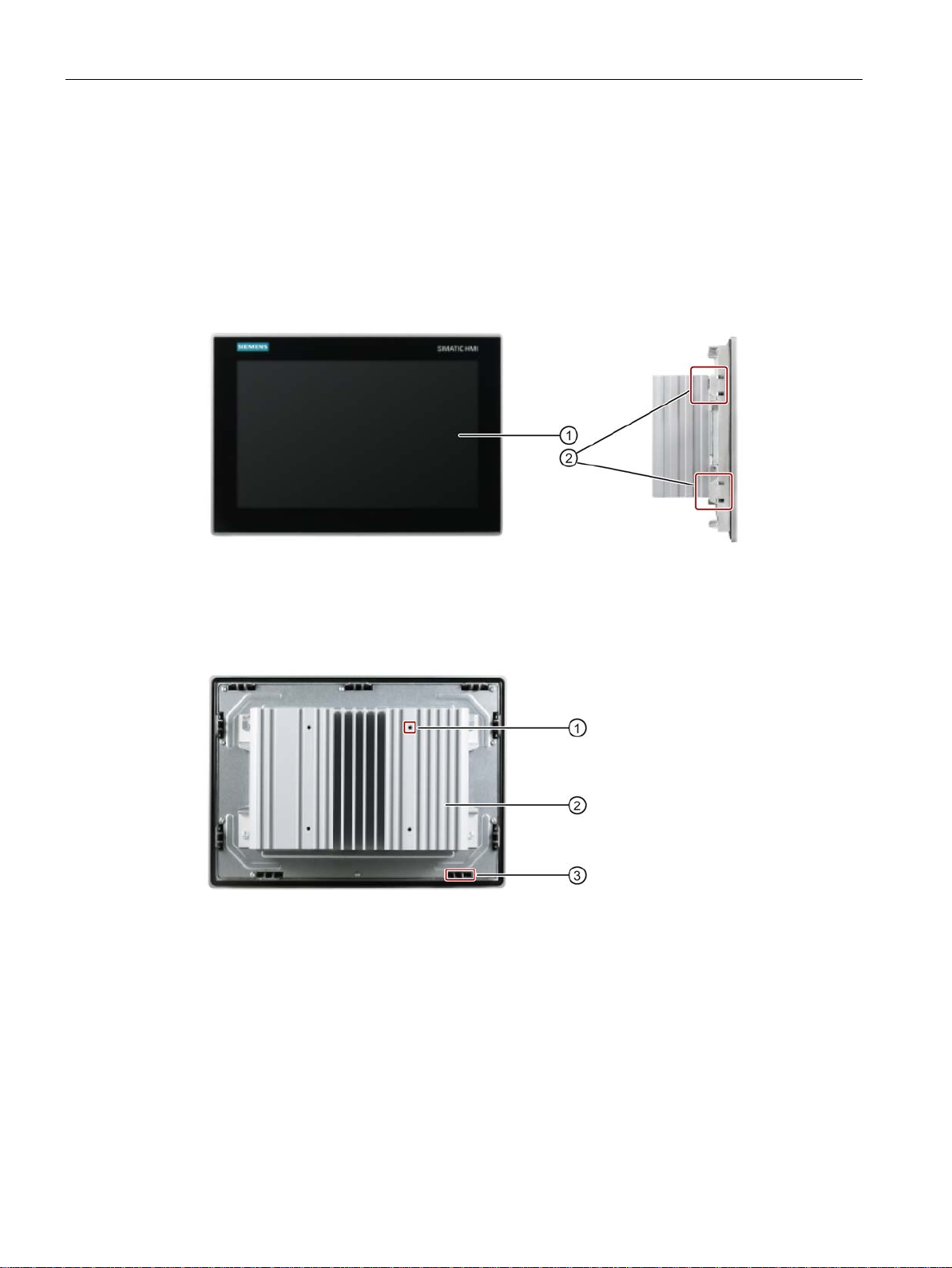
Front and side view
①
Display/touch screen
②
Recesses for mounting clips
Rear view
①
Recesses hole for VESA mounting
②
Cooling fin
③
Recesses for mounting clips
1.2 Structure of the devices
SIMATIC IPC377E
10 Operating Instructions, 2017/05, A5E40965249-AA
Overview
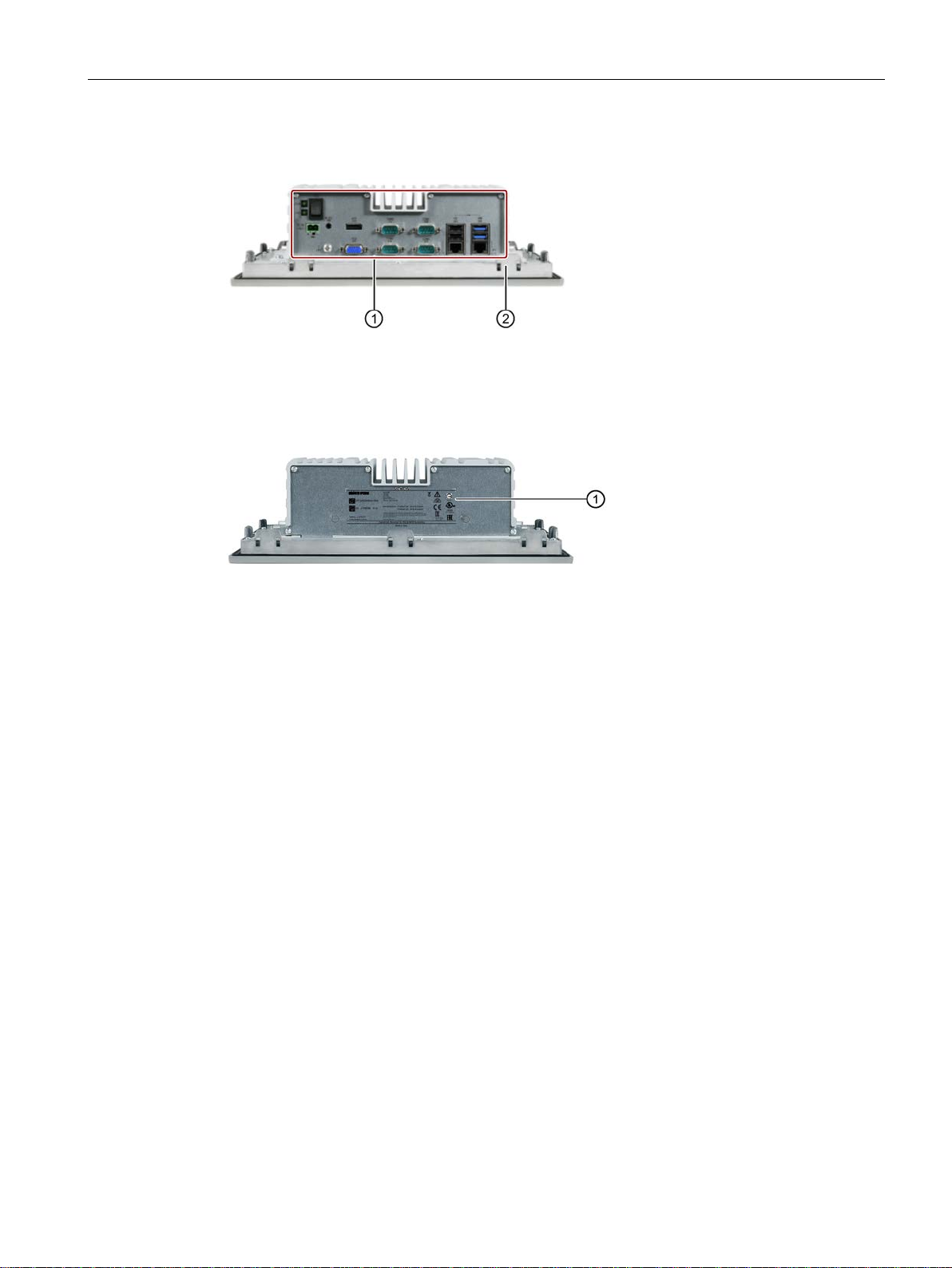
Bottom view
①
Interfaces and operating elements
②
Recesses for mounting clips
Top view
①
Product label
1.2 Structure of the devices
SIMATIC IPC377E
Operating Instructions, 2017/05, A5E40965249-AA
11
Overview
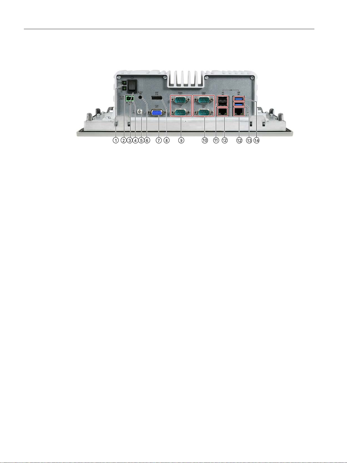
1.2.2
Interfaces and operator controls of the basic device
①
Power status display
②
HDD status display
③
On/off switch.
④
Connection for a
⑤
Function earth
⑥
Connection for analog audio source and speaker
⑦
VGA interface
⑧
Display Port connection
⑨
Serial interface, 9
•
⑩
Serial interface, 9
•
•
•
⑪
USB 2.0, high current
⑫
RJ45 Etherne
⑬
USB 3.0 port 2, high current
⑭
USB 3.0 port 1, high current
1.2 Structure of the devices
RS-232
RS-232
RS-422
RS-485
Observe the printing on the rear of the device.
24 VDC power supply
-pin
-pin
t connection for 10/100/1000 Mbps
SIMATIC IPC377E
12 Operating Instructions, 2017/05, A5E40965249-AA
Overview
1.2.3
Status displays
Display
Meaning
LED
Description
Off
Hibernate, switched off or unplugged
Green
PC is in operation.
Green flashing
standby
Off
No accessing
Green flashing
Accessing data
1.2 Structure of the devices
PWR PC operating status display
HDD Display for hard disk access
SIMATIC IPC377E
Operating Instructions, 2017/05, A5E40965249-AA
13

Overview
1.2 Structure of the devices
SIMATIC IPC377E
14 Operating Instructions, 2017/05, A5E40965249-AA
2
2.1
Security Information
Industrial Security
2.2
General safety instructions
WARNING
Life-threatening voltages are present with an open control cabinet
Siemens provides products and solutions with industrial security functions that support the
secure operation of plants, systems, machines and networks.
In order to protect plants, systems, machines and networks against cyber threats, it is
necessary to implement – and continuously maintain – a holistic, state-of-the-art industrial
security concept. Siemens’ products and solutions only form one element of such a concept.
Customer is responsible to prevent unauthorized access to its plants, systems, machines
and networks. Systems, machines and components should only be connected to the
enterprise network or the internet if and to the extent necessary and with appropriate security
measures (e.g. use of firewalls and network segmentation) in place.
Additionally, Siemens’ guidance on appropriate security measures should be taken into
account. For more information about industrial security, please visit
(http://www.siemens.com/industrialsecurity).
Siemens’ products and solutions undergo continuous development to make them more
secure. Siemens strongly recommends to apply product updates as soon as available and to
always use the latest product versions. Use of product versions that are no longer supported,
and failure to apply latest updates may increase customer’s exposure to cyber threats.
To stay informed about product updates, subscribe to the Siemens Industrial Security RSS
Feed under (http://www.siemens.com/industrialsecurity).
When you install the device in a control cabinet, some areas or components in the open
control cabinet may be carrying life-threatening voltages.
If you touch these areas or components, you may be killed by electric shock.
Switch off the power supply to the cabinet before opening it.
SIMATIC IPC377E
Operating Instructions, 2017/05, A5E40965249-AA
15
Safety instructions
System expansions
NOTICE
Damage through system expansions
WARNING
Risk of fire
NOTICE
"Open Type" UL61010-2-201
2.2 General safety instructions
Device and system expansions may be faulty and can affect the entire machine or plant.
The installation of expansions can damage the device, machine or plant. Device and
system expansions may violate safety rules and regulations regarding radio interference
suppression. If you install or exchange system expansions and damage your device, the
warranty becomes void.
Note the following for system expansions:
● Only install system expansion devices designed for this device. Contact your technical
support team or where you purchased your PC to find out which system expansion
devices may safely be installed.
● Observe the information on electromagnetic compatibility (Page 69).
For vertical installation in upright format, observe the following:
Install the device in an enclosure that meets the requirements of paragraphs 4.6 and 4.7.3
of the standards EN 60950-1:2006 and IEC/UL/EN/DIN-EN 60950-1.
Note that the device is classified as "Open Type" for use in the area of Industrial Control
Equipment (UL61010-2-201). A UL61010-2-201 conform enclosure is therefore a
mandatory requirement for approval or operation according to UL61010-2-201.
SIMATIC IPC377E
16 Operating Instructions, 2017/05, A5E40965249-AA
Safety instructions
Battery
WARNING
Risk of explosion and release of harmful substances
Strong high-frequency radiation
NOTICE
Observe immunity to RF radiation
ESD Guideline
NOTICE
Electrostatic sensitive devices (ESD)
2.2 General safety instructions
Improper handling of lithium batteries can result in an explosion of the batteries.
Explosion of the batteries and the released pollutants can cause severe physical injury.
Worn batteries jeopardize the function of the device.
Note the following when handling lithium batteries:
• Replace used batteries in good time; see the section "Replacing the backup battery
(Page 54)" in the operating instructions.
• Replace the lithium battery only with an identical battery or types recommended by the
manufacturer (type: CR2032).
• Do not throw lithium batteries into fire, do not solder on the cell body, do not recharge,
do not open, do not short-circuit, do not reverse polarity, do not heat above 100°C, and
protect from direct sunlight, moisture and condensation.
The device has an increased immunity to RF radiation according to the specifications on
electromagnetic compatibility in the technical specifications.
Radiation exposure in excess of the specified immunity limits can impair device functions,
result in malfunctions and therefore injuries or damages.
Read the information on immunity to RF radiation in the technical specifications.
Electrostatic sensitive devices can be labeled with an appropriate symbol.
When you touch electrostatic sensitive components, you can destroy them through voltages
that are far below the human perception threshold.
If you work with components that can be destroyed by electrostatic discharge, observe the
ESD Guideline (Page 69).
SIMATIC IPC377E
Operating Instructions, 2017/05, A5E40965249-AA
17

Safety instructions
2.3
Notes on usage
WARNING
Risks associated with the unprotected machine or plant
Environment
NOTICE
Ambient conditions and chemical resistance
2.3 Notes on usage
According to the results of a risk analysis, certain hazard potentials associated with the
unprotected machine exist. These hazards could lead to personal injury.
Avoid such hazards by taking the following precautions in accordance with the risk analysis:
• Installation of additional safety equipment on the machine or plant. In particular, the
programming, parameter assignment and wiring of the inserted I/O must be executed in
accordance with the safety performance identified by the necessary risk analysis (SIL,
PL or Cat.).
• Use as intended must be validated for the device by means of a function test on the
plant. These tests help you to identify programming, parameter assignment and wiring
errors.
• Documentation of the test results that you can enter in the relevant safety verification
documents, if necessary.
Unsuitable environmental conditions have a negative impact on device operation. Chemical
substances such as cleaners or fuels may alter the color, shape and structure of the device
surface, for example, the front panel.
The device may be damaged. possibly resulting in malfunctions.
For this reason, please observe the following precautions:
• Always operate the device in closed rooms. All warranties shall be void in the case of
noncompliance.
• Operate the device only in accordance with the ambient conditions specified in the
technical specifications.
• Protect the device against dust, moisture and heat.
• Do not expose the device to direct sunlight or to other strong sources of light.
• Without additional safety measures, such as a supply of clean air, the device may not be
used in locations with harsh operating conditions caused by acidic vapors or gases.
• Always use suitable cleaning agents. Read the information about chemical resistance in
the Internet, see "SIMATIC IPC after-sales information system
(http://www.siemens.com/asis)".
SIMATIC IPC377E
18 Operating Instructions, 2017/05, A5E40965249-AA

Safety instructions
Note
Use in an industrial environment without additional protective measures
The device has been designed for use in a norma
IEC
TFT displays
NOTICE
Burn-in effect and backlighting
Defective pixels in the display
2.3 Notes on usage
l industrial environment in accordance with
60721-3-3 (pollutant class 3C2 for chemical influences, 3S2 for sand and dust).
A permanent picture with bright screen objects leads to a burn-in effect. The longer the
same screen contents are displayed, the longer it will take for the burn-in effect to
disappear. Screensavers (for example, "starfield simulation") for the backlit active black
mode reduce the burn-in effect. The brightness of the backlighting deteriorates over the
course of the screen's life cycle.
The service life of the screen and backlighting is extended by the following measures:
• Switch on the screensaver. The backlight brightness is reduced while the screensaver is
active.
• You should also reduce the backlighting.
• Observe the backlighting operating time.
At present, the manufacturing process of modern displays does not guarantee that all pixels
of the display will be perfect. A small number of defective pixels in the display is therefore
unavoidable. This does not present a functional problem as long as the defective pixels are
not bunched in one location.
Additional information is available in the section "Technical specifications (Page 67)".
SIMATIC IPC377E
Operating Instructions, 2017/05, A5E40965249-AA
19

Safety instructions
2.3 Notes on usage
SIMATIC IPC377E
20 Operating Instructions, 2017/05, A5E40965249-AA

3
3.1
Preparing for installation
3.1.1
Checking the delivery package
Procedure
Note
Damage to the device during transport and storage
If a device is transported or stored without packaging, shocks, vibrations, pressure and
moisture may impact the unprotected unit. A damaged packaging indicates that ambient
conditions have already had a massive impact on the device
The device may be damaged.
Do not dispose of the original packaging. Pack the device during transportation and
storage.
1. When accepting a delivery, please check the packaging for visible transport damage.
2. If any transport damage is present at the time of delivery, lodge a complaint at the
shipping company in charge. Have the shipper confirm the transport damage
immediately.
3. Unpack the device at its installation location.
4. Keep the original packaging in case you have to transport the unit again.
.
5. Check the contents of the packaging and any accessories you may have ordered for
completeness and damage. You will find the accessories, such as mounting hardware
and Ethernet connector strain relief, under the foam insert in the box.
SIMATIC IPC377E
Operating Instructions, 2017/05, A5E40965249-AA
21
Installing and connecting the device
WARNING
Electric shock and fire hazard due to damaged device
NOTICE
Damage from condensation
3.1.2
Identification data of the device
Order number
6AV...
Serial number
S V
Product version
FS
Windows "Product Key"
Ethernet address 1 (MAC)
Ethernet address 2 (MAC)
3.1 Preparing for installation
6. If the contents of the packaging are incomplete, damaged or do not match your order,
inform the responsible delivery service immediately. Fax the enclosed form "SIMATIC
IPC/PG Quality Control Report".
A damaged device can be under hazardous voltage and trigger a fire in the machine or
plant. A damaged device has unpredictable properties and states.
Death or serious injury could occur.
Make sure that the damaged device is not inadvertently installed and put into operation.
Label the damaged device and keep it locked away. Send off the device for immediate
repair.
If the device is subjected to low temperatures or extreme fluctuations in temperature
during transportation, for example in cold weather, moisture could build up on or inside
the HMI device.
Moisture causes a short circuit in electrical circuits and damages the device.
In order to prevent damage to the device, proceed as follows:
• Store the device in a dry place.
• Bring the device to room temperature before starting it up.
• Do not expose the device to direct heat radiation from a heating device.
• If condensation develops, wait approximately 12 hours or until the device is
completely dry before switching it on.
7. Please keep the enclosed documentation in a safe place. It belongs to the device. You
need the documentation when you commission the device for the first time.
8. Write down the identification data of the device.
The device can be clearly identified with the help of this identification data in case of repairs
or theft.
Enter the identification data in the following table:
SIMATIC IPC377E
22 Operating Instructions, 2017/05, A5E40965249-AA
Installing and connecting the device
Procedure
Note
Replacement device without storage media
When you order a replacement device, remove all the storage
for example HDD. Insert the storage media in the replacement device.
Example of a COA label
3.1 Preparing for installation
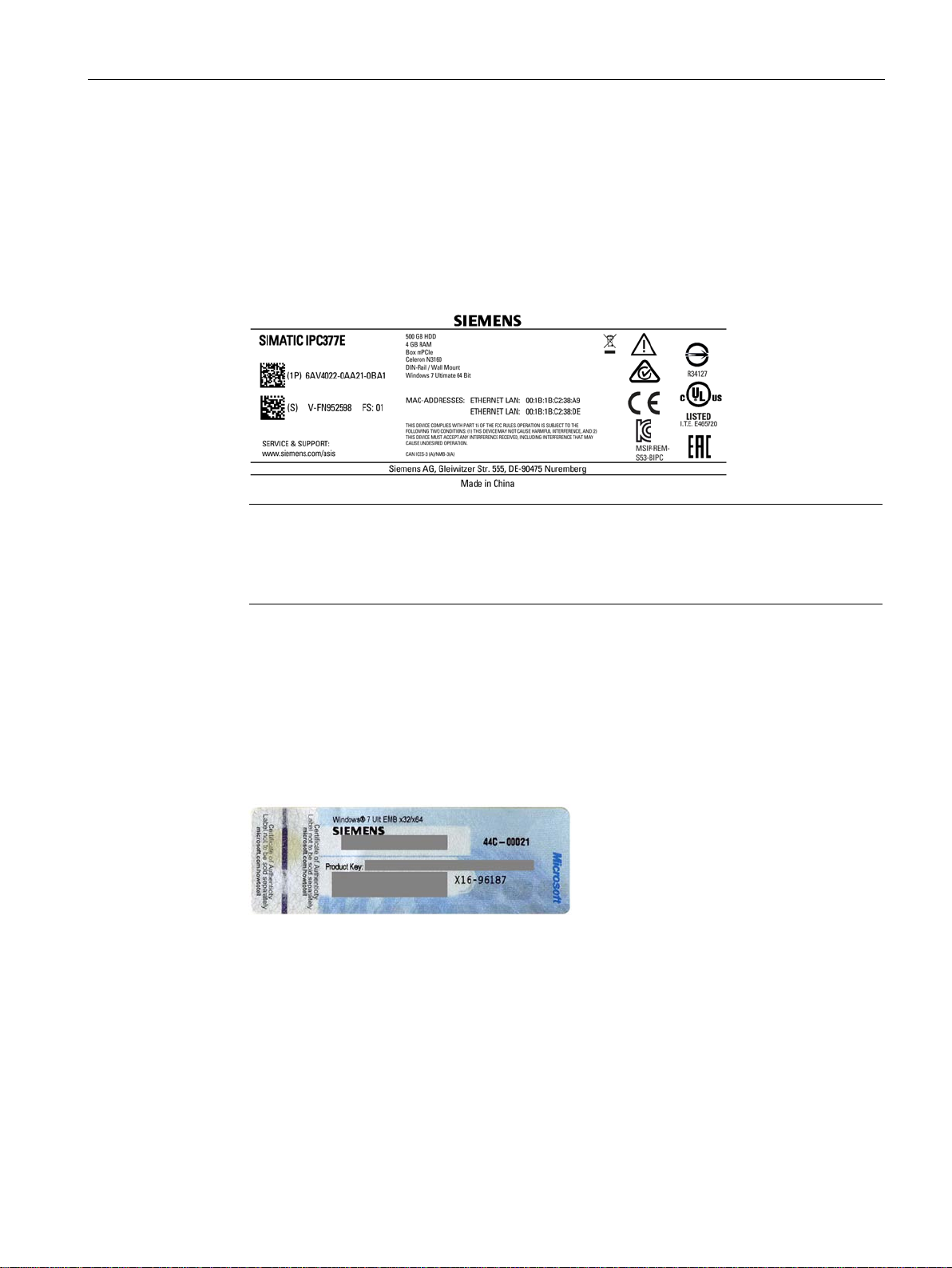
You can find this information on the rating plate and COA label. The rating plate is located on
the back of the unit. The COA label is only available with pre-installed Windows operating
systems and is affixed to the rear of the device.
1. Transfer order number, serial number, production version (FS), and Ethernet addresses
from the rating plate. Below is an example of a product label.
2. Take down the Windows "Product Key" from the COA label.
Microsoft Windows "Product Key" on the "Certificate of Authenticity" (COA):
The COA label is only attached to the rear of the device containing a Windows Embedded
Standard 7 or Windows 7 operating system.
● COA label of a device with Windows 7 operating system
media from your device,
SIMATIC IPC377E
Operating Instructions, 2017/05, A5E40965249-AA
23
Installing and connecting the device
3.1.3
Permitted mounting positions
Maximum ambient tem-
perature at the device
Comment
sure.
Maximum ambient tem-
perature at the device
Comment
3.1 Preparing for installation
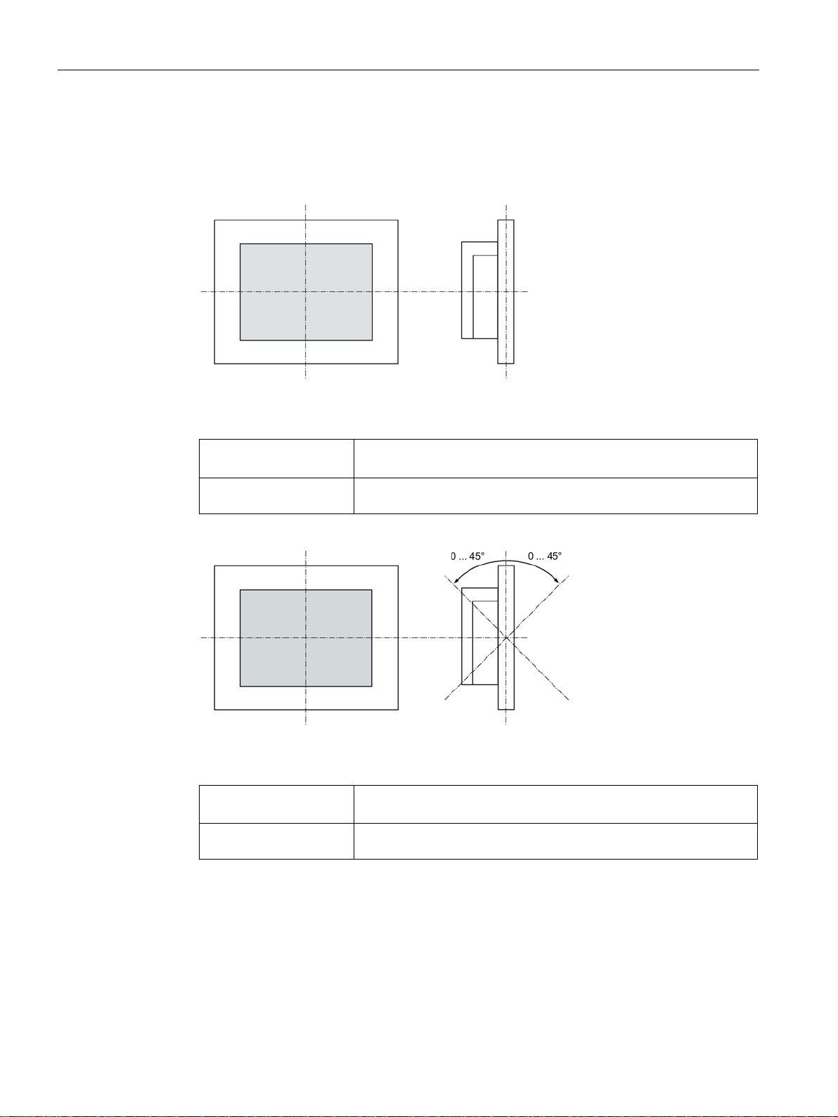
The device may be mounted in the following positions:
● Standard position: Vertical installation in horizontal format
For vertical installation in horizontal format, the following ambient temperatures are
permitted:
40 °C The device enclosure fulfills the requirement of a fire protection enclo-
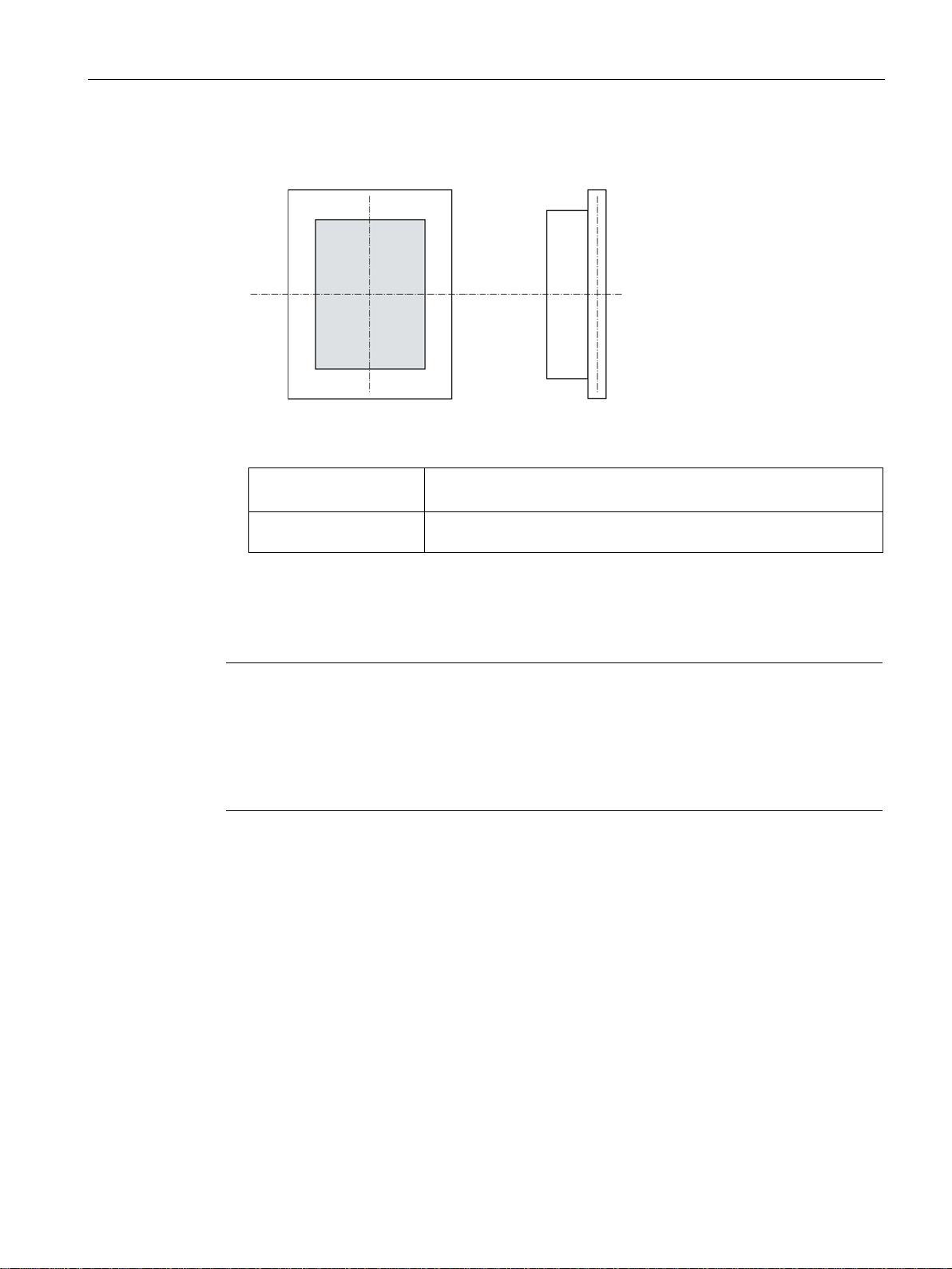
● Inclined installation in horizontal format with a vertical inclination of maximum ±45 °
For inclined installation in horizontal format, the following ambient temperatures are
permitted:
40 °C The device enclosure fulfills the requirement of a fire protection enclo-
sure.
SIMATIC IPC377E
24 Operating Instructions, 2017/05, A5E40965249-AA
Installing and connecting the device
Maximum ambient tem-
perature at the device
Comment
"General safety instructions (Page 15)").
3.1.4
Preparing the mounting cutout
Note
Stability of the mounting cutout
The material in the area of the mounting cutout must provide sufficient strength to guarantee
the enduring and safe mounting of the HMI device.
To achieve the degrees of prote
of the material cannot occur due to the force of the mounting clips or operation of the device.
Degrees of protection
3.1 Preparing for installation
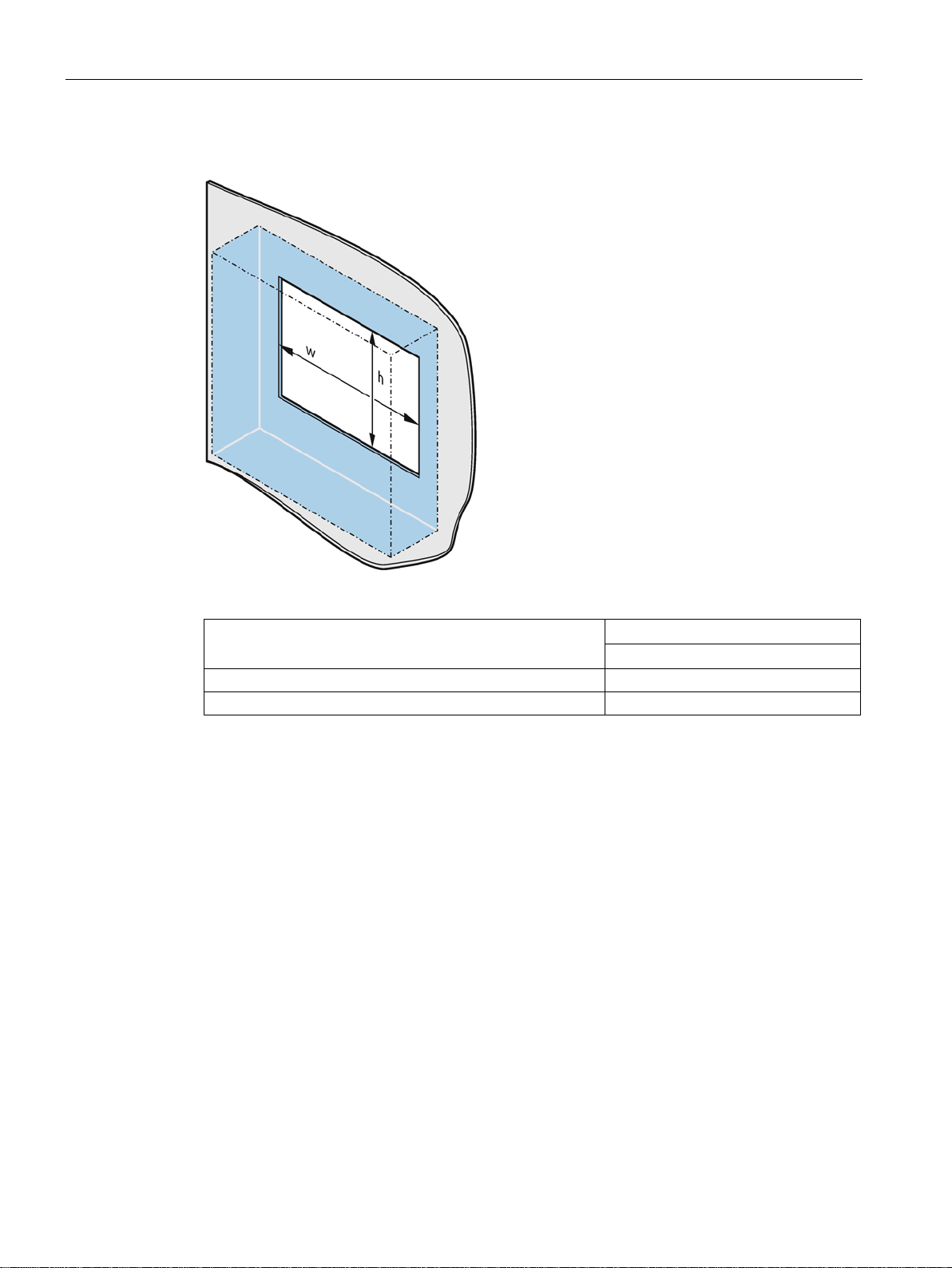
● Vertical installation in upright format, display turned through ±90 ° compared with the
standard position
For vertical installation in upright format, the following ambient temperatures are
permitted:
40 °C The device must be installed in a fire protection enclosure (see
The degrees of protection of the HMI device can only be guaranteed if the following
requirements are met:
● Material thickness at the mounting cutout for IP65 degree of protection, or for
enclosure type 4X/type 12 (indoor use only): 2 mm to 6 mm
● Permissible deviation from plane at the mounting cutout: ≤ 0.5 mm
This condition must be fulfilled for the mounted HMI device.
● Permissible surface roughness in the area of the seal: ≤ 120 µm (R
ction described below, it must be ensured that deformation
120)
z
SIMATIC IPC377E
Operating Instructions, 2017/05, A5E40965249-AA
25
Installing and connecting the device
Dimensions of the mounting cutout
Mounting cutout
Device
12 inch
Width w *
302+1 mm
Height h *
208+1 mm
*
Width and height should be reversed accordingly when mounting in vertical format.
3.1 Preparing for installation
The following table shows the dimensions of the required mounting cutout:
SIMATIC IPC377E
26 Operating Instructions, 2017/05, A5E40965249-AA
Installing and connecting the device
3.2
Installing the device
3.2.1
Installation guidelines
WARNING
Dangerous voltage in control cabinet
NOTICE
Risk of fire
Note
In the standard installation position, the device meets the requirements for fire protection
enclosures in accordance with EN 60950-1. It can therefore be installed without an additional
fire protection covering.
3.2 Installing the device
The installer of the plant is responsible for proper installation of the device.
A high voltage may be present in the switchgear cabinet and could cause a dangerous
electric shock.
It may result in death or serious physical injury.
Isolate the power supply to the control cabinet before opening it. Ensure that the power to
the control cabinet cannot be turned on accidentally.
If you install the device in an unapproved mounting position or if you do not observe the
ambient conditions, the device can overheat.
Overheating can cause a fire. Proper functioning of the device is no longer guaranteed.
Before you install the device, note the following general installation information.
● Install the device only in one of the permitted mounting positions.
● For installation in a control cabinet, observe the applicable country-specific regulations.
● Ensure that the device is classified as "Open Type" when using it in the area of Industrial
Control Equipment (UL61010-2-201). A UL61010-2-201 conform enclosure is therefore a
mandatory requirement for approval or operation according to UL61010-2-201.
● Provide adequate volume in the control cabinet for air circulation and heat transport.
Keep at least 5 cm distance between the device and control cabinet.
● The ventilation slots of the device may not be covered or obstructed.
● The minimum distance between the device and the cabinet is 5 cm at the air output end.
● Ensure there is enough free space in the control cabinet to allow the cover to be
removed.
● Equip the control cabinet with struts for stabilizing the mounting cut-out. Install struts
where necessary.
SIMATIC IPC377E
Operating Instructions, 2017/05, A5E40965249-AA
27
Installing and connecting the device
IP65 degree of protection
WARNING
Risk of electric shock
3.2.2
Secure with mounting clips
Positions of the mounting clips
HMI device
Mounting clips
Type
Quan-
tity
Position on the HMI device
Requirement
3.2 Installing the device
The specified degree of protection cannot be guaranteed if the device is not correctly
installed. Moisture or water could leak in and cause electric shock or destroy the plant.
The degree of protection IP65 is ensured for the front of the device under the following
conditions:
• The mounting cutout was prepared based on the correct dimensions; see chapter
"Preparing the mounting cutout (Page 25)".
• The device was secured with the supplied mounting clamps or with clamps which can
be optionally ordered.
• The mounting seal is undamaged.
To achieve the degree of protection for the HMI device, the positions for the mounting clips
shown below must be adhered to.
The positions of the mounting clips are marked by stamps on the cutouts. Fit the mounting
clips in all the stamped cutouts.
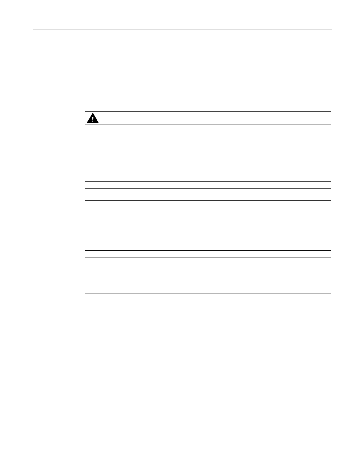
The following table shows the type, number, and position of the mounting clips needed for
the respective HMI devices.
12" display
9
SIMATIC IPC377E
28 Operating Instructions, 2017/05, A5E40965249-AA
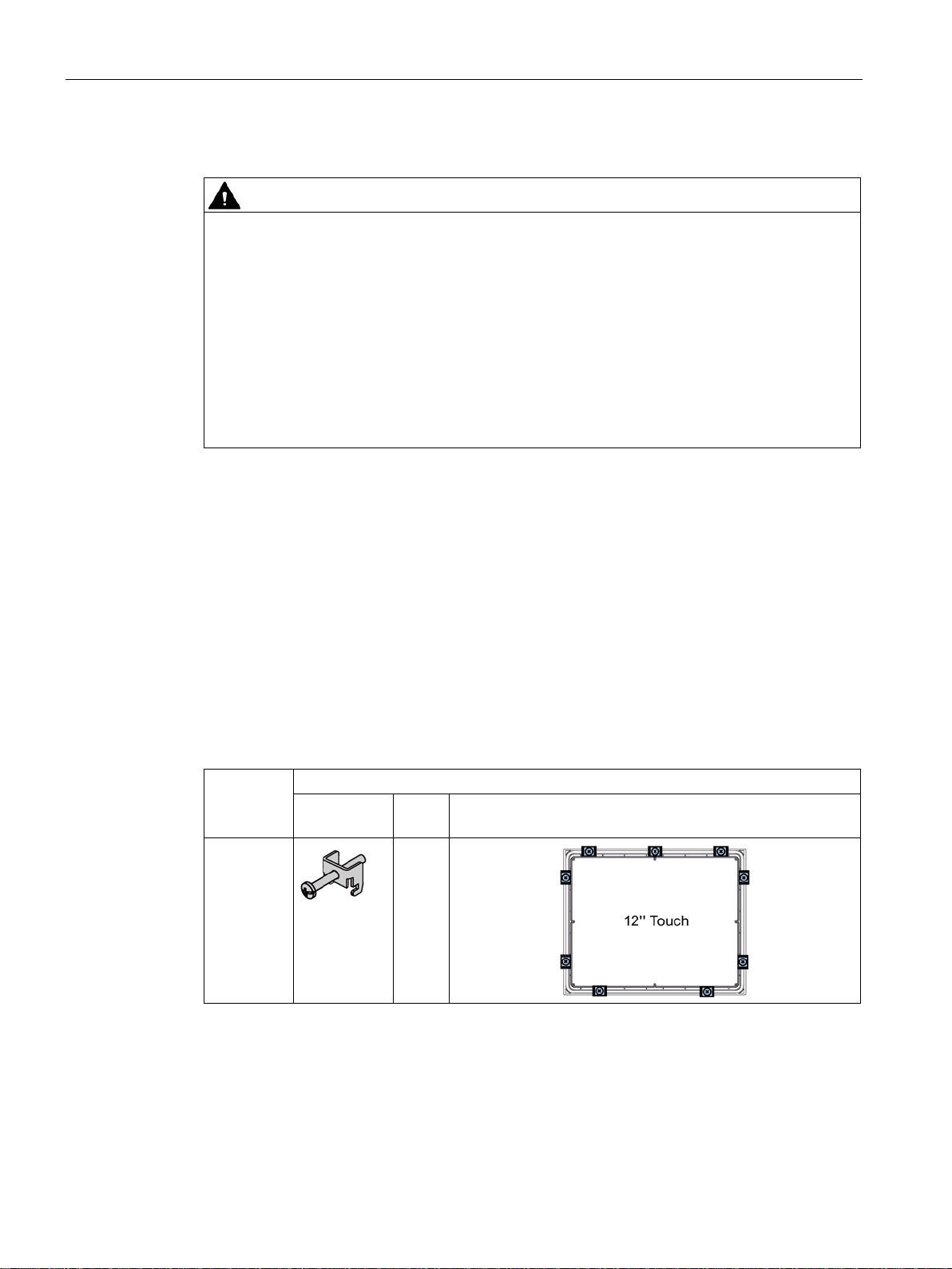
● All packaging components and protective films should be removed from the device.
● To install the panel, you need the mounting clips from the accessories kit.
Installing and connecting the device
Procedure
Insert the panel device into the mounting
cutout from the front.
Insert a mounting clip into the cutout
provided on the device.
Tighten the threaded pin to secure the
mounting clip. The threaded pins have a
maximum tightening torque of 0.5 Nm on
the 12 inch variants.
Repeat steps 2 and 3 for all mounting
clips.
Check the fit of the mounting seal.
Result
3.2 Installing the device
The device is mounted and the relevant degree of protection is ensured at the front.
SIMATIC IPC377E
Operating Instructions, 2017/05, A5E40965249-AA
29
Installing and connecting the device
3.2.3
VESA mounting
Requirements
Procedure
Note
Make sure your support application is VESA100 compliant. Otherwise, you can not use it to
support IPC377E.
Note
Observe the torques
If you use too much
support arm or stand, the support arm may be damaged. If you tighten the screws with a
torque that is too low
Tighten the screws with the following torques, which
Adhere to the torque specifications of the third
1.5
3.2 Installing the device
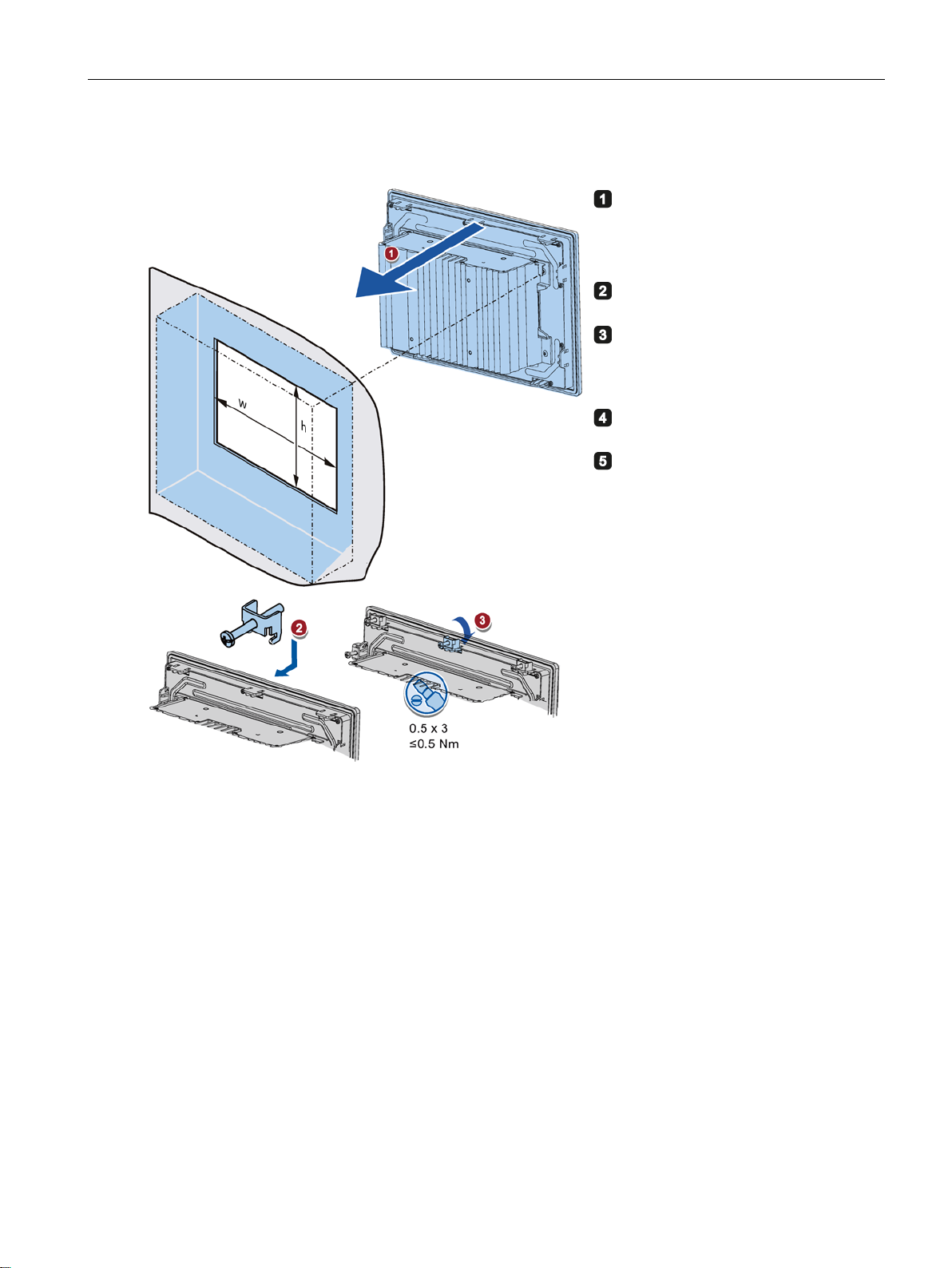
IPC377E is VESA (Video Electronics Standards Association) compliant and can be mounted
on all kinds of applications utilizing the standard VESA100 mounting interfaces.
Its rear panel provides access to retention screw holes that support VESA mounting.
● All packaging components and protective films have been removed.
● VESA support application (for example, an arm or a stand) from a third party
torque to tighten the screws of the screws for fastening the device to a
, the device is not sealed.
may not be exceeded.
-party vendors:
Nm for connecting the device and the VESA mounting interface.
Secure the device to the mounting interface with four M4 x 10 screws.
SIMATIC IPC377E
30 Operating Instructions, 2017/05, A5E40965249-AA
 Loading...