

Siemens SIMATIC IPC347E Operating Instructions Manual

___________________
___________________
___________________
___________________
___________________
___________________
___________________
___________________
___________________
___________________
___________
___________________
___________________
SIMATIC
Industrial PC
SIMATIC IPC347E
Operating Instructions
09/2018
A
Preface
Overview
1
Safety instructions
2
Installing and connecting the
device
3
Commissioning the device
4
Installing hardware
expansions
5
Device maintenance
6
Technical specifications
7
Appendix Motherboard
A
Appendix BIOS
B
Appendix The pin definition
of ATX power supply output
connector
C
Appendix Technical support
D
Appendix List of
abbreviations
E
5E41134132-AE

Siemens AG
Divis ion D igital Fac tory
Postf ach 48 48
90026 NÜRNBERG
GERMANY
A5E41134132-AE
Ⓟ
Copyright © Siemens AG 2018.
All rights res erved
Legal information
Warning notice system
DANGER
indicates that death or severe personal injury will result if proper precautions are not taken.
WARNING
indicates that death or severe personal injury may result if proper precautions are not taken.
CAUTION
indicates that minor personal injury can result if proper precautions are not taken.
NOTICE
indicates that property damage can result if proper precautions are not taken.
Qualified Personnel
personnel qualified
Proper use of Siemens products
WARNING
Siemens products may only be used for the applications described in the catalog and in the relevant technical
Trademarks
Disclaimer of Liability
This manual contains notices you have to observe in order to ensure your personal safety, as well as to prevent
damage to property. The notices referring to your personal safety are highlighted in the manual by a safety alert
symbol, notices referring only to property damage have no safety alert symbol. These notices shown below are
graded according to the degree of danger.
If more than one degree of danger is present, the warning notice representing the highest degree of danger will
be used. A notice warning of injury to persons with a safety alert symbol may also include a warning relating to
property damage.
The product/system described in this documentation may be operated only by
task in accordance with the relevant documentation, in particular its warning notices and safety instructions.
Qualified personnel are those who, based on their training and experience, are capable of identifying risks and
avoiding potential hazards when working with these products/systems.
Note the following:
documentation. If products and components from other manufacturers are used, these must be recommended
or approved by Siemens. Proper transport, storage, installation, assembly, commissioning, operation and
maintenance are required to ensure that the products operate safely and without any problems. The permissible
ambient conditions must be complied with. The information in the relevant documentation must be observed.
All names identified by ® are registered trademarks of Siemens AG. The remaining trademarks in this publication
may be trademarks whose use by third parties for their own purposes could violate the rights of the owner.
We have reviewed the contents of this publication to ensure consistency with the hardware and software
described. Since variance cannot be precluded entirely, we cannot guarantee full consistency. However, the
information in this publication is reviewed regularly and any necessary corrections are included in subsequent
editions.
for the specific
09/2018 Subject to change

Preface
Purpose of the Operating Instructions
Validity of the Operating Instructions
Conventions
Basic knowledge required
Position in the information landscape
This operating instruction contains all the information you need for commissioning and
operating SIMATIC IPC347E.
This operating instruction is intended for the following personnel:
● programming and testing personnel who commission the device and connect it with the
peripheral equipment.
● service and maintenance personnel who install add-ons or carry out fault/error analyses.
These operating instructions are valid for all supplied versions of the SIMATIC IPC347E.
The updates of the document will be published on the Siemens technical support
(https://support.industry.siemens.com).
The terms "PC" or "device" are sometimes used in place of the product name SIMATIC
IPC347E in these operating instructions.
Knowledge of personal computers and Microsoft operating systems is required.
General knowledge of automation control engineering is recommended.
The documentation for the SIMATIC IPC347E includes the following sections:
● SIMATIC IPC347E, Quick Install Guide
● SIMATIC IPC347E, Important Notes Product Information
● SIMATIC IPC347E, Operating Instructions
The Quick Install Guide and the "Documentation and Drivers" DVD are in the accessory box
supplied with the product. The Operating Instructions is part of the "Documentation and
Drivers" DVD.
For further instructions on how to handle the software, refer to the corresponding
documentation.
SIMATIC IPC347E
Operating Instructions, 09/2018, A5E41134132-AE
3

Preface
History
Version
Comments
02/2016
The first edition
08/2017
The second edition
10/2017
The third edition
07/2018
Add the workaround for the Windows boot problem caused by SATA selection.
09/2018
Add the information that complies with UL61010.
Currently released versions of these operating instructions.
Table 1 Versions for the IPC347E
SIMATIC IPC347E
4 Operating Instructions, 09/2018, A5E41134132-AE

Table of contents
Preface ................................................................................................................................... 3
1 Overview ................................................................................................................................ 9
2 Safety instructions ...................................................................................................................17
3 Installing and connecting the device ...........................................................................................25
4 Commissioning the device ........................................................................................................37
5 Installing hardware expansions ..................................................................................................41
1.1 Product description .............................................................................................................. 9
1.2 Design of the device .......................................................................................................... 11
1.2.1 Exterior design .................................................................................................................. 11
1.2.2 Operator controls............................................................................................................... 15
2.1 Security information ........................................................................................................... 17
2.2 General safety instructions ................................................................................................ 18
2.3 Headphones ...................................................................................................................... 21
2.4 Notes on use ..................................................................................................................... 22
3.1 Preparing for installation .................................................................................................... 25
3.1.1 Checking the delivery package .......................................................................................... 25
3.1.2 Device identification data ................................................................................................... 26
3.2 Installing the device ........................................................................................................... 28
3.2.1 Installation information ....................................................................................................... 28
3.2.2 Mounting location and position........................................................................................... 29
3.3 Connecting the device ....................................................................................................... 31
3.3.1 Connection information ...................................................................................................... 31
3.3.2 Connecting the function earth ............................................................................................ 32
3.3.3 Connecting the power supply ............................................................................................. 33
3.3.4 Connecting the device to networks .................................................................................... 35
3.3.5 Dual-monitoring ................................................................................................................. 36
4.1 Requirements for commissioning ....................................................................................... 37
4.2 Initial commissioning ......................................................................................................... 37
4.3 Switching off the device ..................................................................................................... 38
5.1 Opening the device............................................................................................................ 41
5.2 Expansion cards ................................................................................................................ 42
5.2.1 Notes on the expansion cards............................................................................................ 42
5.2.2 Installing expansion cards ................................................................................................. 43
5.3 Disk drives ........................................................................................................................ 45
5.3.1 Installation options for drives ............................................................................................. 45
5.3.2 Removing the drive module ............................................................................................... 45
5.3.3 Installing drives or hard disks ............................................................................................. 46
5.3.4 Removing and installing internal hard disks ....................................................................... 48
SIMATIC IPC347E
Operating Instructions, 09/2018, A5E41134132-AE
5

Table of contents
6 Device maintenance ................................................................................................................ 49
7 Technical specifications ........................................................................................................... 69
A Appendix Motherboard ............................................................................................................ 83
6.1 Repair information ..............................................................................................................49
6.2 Recycling and disposal .......................................................................................................50
6.3 Maintenance ......................................................................................................................51
6.3.1 Maintenance intervals.........................................................................................................51
6.3.2 Replacing filters..................................................................................................................51
6.3.3 Beep code ..........................................................................................................................52
6.4 Removing and installing hardware components ..................................................................53
6.4.1 Removing the device fan ....................................................................................................53
6.4.2 Installing memory module ...................................................................................................54
6.4.3 Replacing the backup battery .............................................................................................56
6.4.4 Removing the power supply ...............................................................................................57
6.4.5 Removing the motherboard ................................................................................................58
6.4.6 Replacing the processor .....................................................................................................58
6.5 Installing the software .........................................................................................................61
6.5.1 Source for installation of the operating system ....................................................................61
6.5.2 Restoring the delivery state ................................................................................................61
6.5.3 Installing Windows..............................................................................................................64
6.5.3.1 Installation of Windows 7 ....................................................................................................64
6.5.4 Installing drivers and software ............................................................................................67
7.1 Certificates and approvals ..................................................................................................69
7.2 Guidelines and declarations ...............................................................................................72
7.2.1 Electromagnetic compatibility .............................................................................................72
7.3 Dimension drawings ...........................................................................................................72
7.3.1 Dimension drawing of the device ........................................................................................72
7.3.2 Dimensional drawings for the installation of expansion cards ..............................................73
7.3.3 Dimension drawing for the use of telescopic rails ................................................................74
7.4 Technical data ....................................................................................................................74
7.4.1 General technical specifications .........................................................................................74
7.4.2 Power requirements of the components (maximum values) ................................................79
7.4.3 Basic power supply ............................................................................................................79
7.4.4 Telescopic rails ..................................................................................................................80
7.4.5 Power cable .......................................................................................................................80
7.5 BIOS description ................................................................................................................81
A.1 Motherboard general ..........................................................................................................83
A.2 Jumpers .............................................................................................................................84
A.3 Internal Connector ..............................................................................................................87
A.3.1 Fan connector ....................................................................................................................87
A.3.2 Front panel connector (F_Panel1 & F_Panel2) ....................................................................88
A.3.3 Internal USB 2.0 connector (USB 2_56 & USB 2_78) ..........................................................89
A.3.4 Internal RS-232 COM Connector (COM3 & COM4) ............................................................90
A.3.5 Internal DIO Connector (DIO1) ...........................................................................................91
A.3.6 Internal LPT Connector (LPT1 – Parallel Port) ....................................................................92
SIMATIC IPC347E
6 Operating Instructions, 09/2018, A5E41134132-AE

Table of contents
B Appendix BIOS ..................................................................................................................... 101
C Appendix The pin definition of ATX power supply output connector ................................................ 121
D Appendix Technical support .................................................................................................... 123
E Appendix List of abbreviations ................................................................................................. 127
Glossary .............................................................................................................................. 133
Index ................................................................................................................................... 145
A.3.7 Internal USB 2.0 Vertical Connector (USB2_9) .................................................................. 93
A.3.8 ATX power 24-pin connector (EATX_PWR1) ..................................................................... 94
A.3.9 ATX Power 4-pin connector (EATX_PWR2) ....................................................................... 95
A.3.10 Intel CPU socket(LGA1) .................................................................................................... 95
A.3.11 DDR3 Memory sockets ...................................................................................................... 95
A.3.12 SATA 3.0/6.0 Gbps Port Connectors (SATA6G_1/ SATA6G_2/ SATA3G_3/
SATA3G_4) ....................................................................................................................... 96
A.3.13 Battery socket ................................................................................................................... 96
A.4 Installing drivers ................................................................................................................ 97
A.4.1 Installing the drivers on Windows 7 .................................................................................... 97
B.1 BIOS getting started .........................................................................................................101
B.2 Main setup .......................................................................................................................102
B.3 Advanced setup................................................................................................................104
B.4 Chipset setup ...................................................................................................................111
B.5 Boot Setup .......................................................................................................................115
B.6 Security setup ..................................................................................................................117
B.7 Save and Exit ...................................................................................................................119
D.1 Service and support..........................................................................................................123
D.2 Problem solving ................................................................................................................124
D.2.1 General information ..........................................................................................................124
SIMATIC IPC347E
Operating Instructions, 09/2018, A5E41134132-AE
7

Table of contents
SIMATIC IPC347E
8 Operating Instructions, 09/2018, A5E41134132-AE
1
1.1
Product description
The SIMATIC IPC347E is an industrial PC in 19" rack format design (4U).
● Powerful processors up to Intel Core i5 (4th generation)
● No additional dust protection measures required thanks to filter mat and overpressure
ventilation
● Robust all-metal enclosure
● Variety of interfaces
● Lockable front cover
● Prepared for mounting on telescopic rails
SIMATIC IPC347E
Operating Instructions, 09/2018, A5E41134132-AE
9

Overview
SIMATIC IPC347E configuration plan
State Drive(SSD)
Display
integrated graphic engine support up to 1920 x1200 pixels
Power Supply
100V to 240V AC
Audio (line in, line out, mic)
Front LEDs
Power supply status, Hard disk status
1
More language packages are available on the recovery DVD. You can install them as your
need.
2
If you need interface extension, refer to the interface configuration in General technical
specifications
1.1 Product description
Type
Mounting
Chipset
CPU type
Memory
Hard Disk
Drive(HDD) or Solid
• 19" rack, 4 U
• support horizontal installation
• Intel® H81
• Intel® Pentium® Dual Core™ G3420 (2C/2T; 3.2 GHz; 3 MB cache)
• Intel® Core™ i5-4570S (4C/4T; 2.9 (3.6) GHz; 6 MB cache)
• 2 GB DDR3-1600
• 4 GB DDR3-1600
• 8 GB DDR3-1600
500 GB or 1 TB HDD, or 256 GB SSD
Drive bays
Optical Driver
Operation System
Expansion slot
Interface 2 x USB 3.0 (rear), 5 x USB 2.0 (2x in the front, 2x in the rear, 1x internal), 2 x COM 2
• 1 x 3.5" slot
• 3 x 5.25" slot
• DVD-R/W
• Without
• Windows 7 Ultimate. Multi-Language (English version is preinstalled) 1, 64-Bit, SP1
• Without
• 4 x PCI
• 1 x PCIe x 1; Gen2.0
• 1 x PCIe x 8 (2 lanes); Gen2.0
• 1 x PCIe x 16 ; Gen2.0
(RS232/RS422/RS485), 2 x Ethernet (RJ45, 10/100/1000Mbit/s), 1 x VGA, 1 x DVI-D, 2 x PS/2,
(Page 74).
SIMATIC IPC347E
10 Operating Instructions, 09/2018, A5E41134132-AE
Overview
1.2
Design of the device
1.2.1
Exterior design
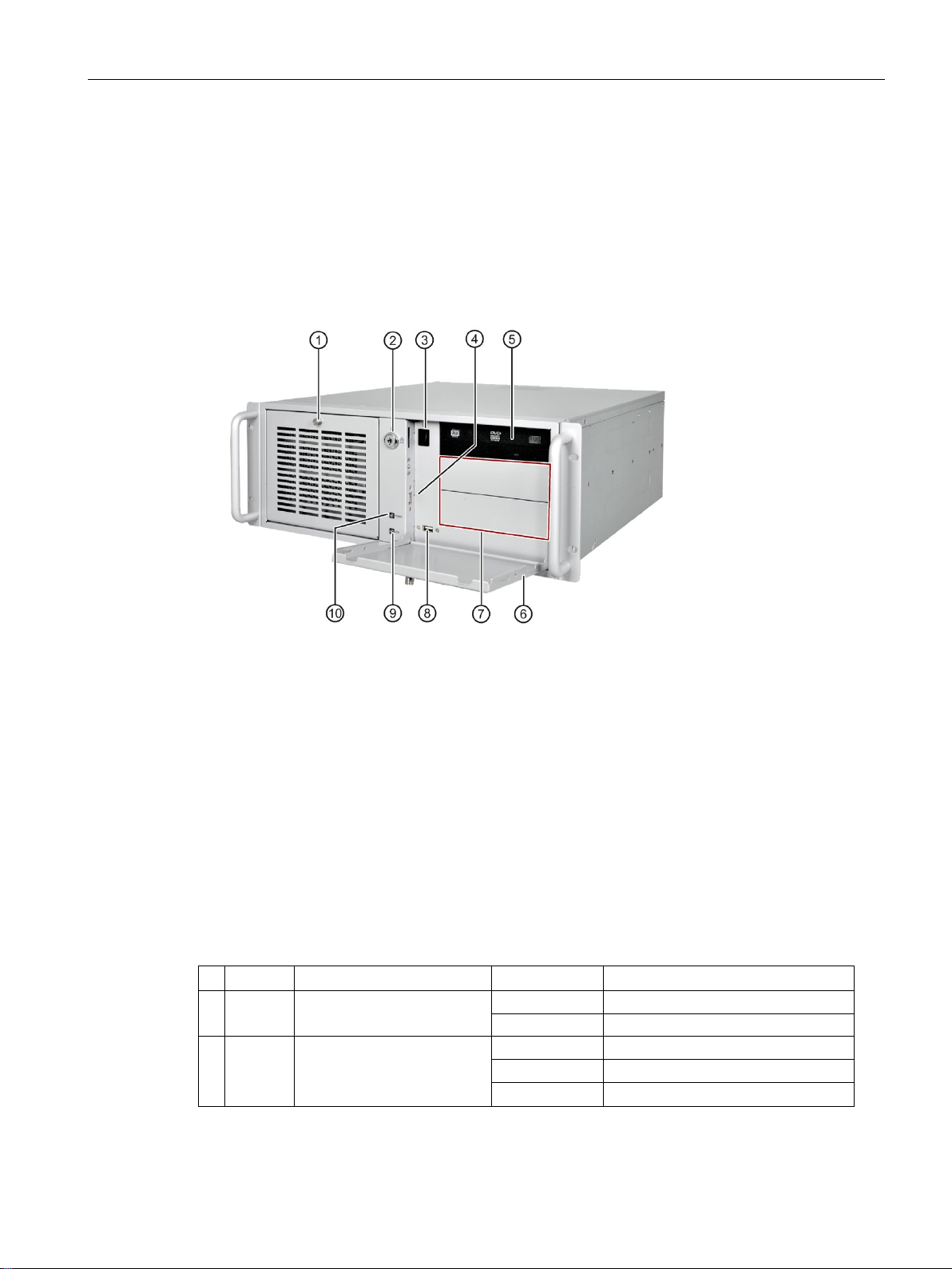
Front view
①
Front left door
⑥
Front right door
②
Lock
⑦
Drive bays 2 x 5.25"
③
On/off button
⑧
Connections for
ible with USB 1.1 1
④
Connection for USB 2.0 devices,
compa
⑨
HDD status display
⑤
Drive bay
⑩
Power status display
1
Each USB port can be disabled/enabled separately by disabling/enabling the associated
U
A
Display
Meaning
LED
Description
⑨
Off
No accessing
Green flashing
Accessing data
⑩
Off
Hibernate, switched off or unplugged
Green
PC is in operation.
Green flashing
standby
1.2 Design of the device
tible with USB 1.1 1
SB port in BIOS. On how to disable/enable the USB port, see USB configuration in
dvanced setup (Page 104).
HDD Display for hard disk access
Power PC operating status display
USB 2.0 devices, compat-
SIMATIC IPC347E
Operating Instructions, 09/2018, A5E41134132-AE
11
Overview
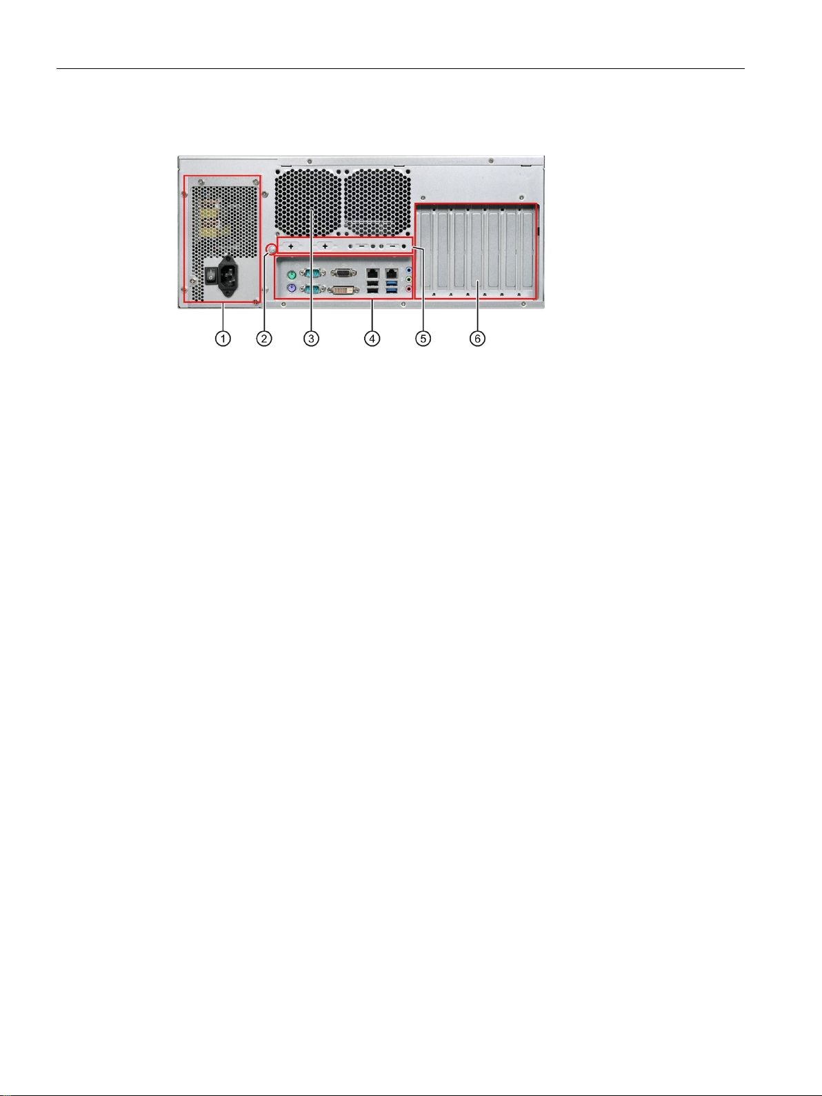
Rear view
①
Power supply
②
Function earth
③
Air outlet
④
Interfaces
⑤
Extensible interface
⑥
Expansion slots for:
•
•
•
•
1.2 Design of the device
4 × PCI
1 × PCle × 1
1 × PCIe x 8 (2 lanes)
1 × PCIe x 16
SIMATIC IPC347E
12 Operating Ins tructions, 09/2018, A5E41134132-AE
Overview
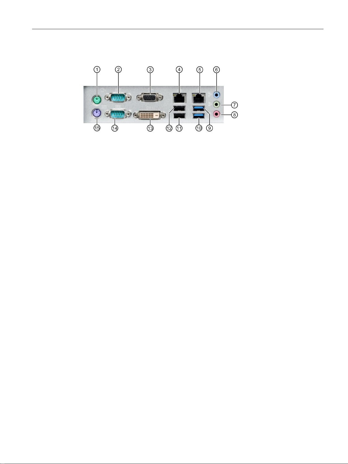
Interfaces
①
Mouse Port
Connection for a PS/2 mouse
②
COM
Serial interface 1 (V.24), 9
Default setting: RS-232/RS422/RS485.
③
VGA
Connection for monitor with VGA interface
④
LAN2
RJ
listed in Component label.
⑤
LAN1 1
RJ‐45 Ethernet Port for 10/100/1000Mbps LAN, the MAC-Address is
listed in Component label.
⑥
Line i
Connection for analog audio source, 3.5 mm phono jack
⑦
Line out (green)
Connection for active speakers or headset, 3.5 mm phono jack
⑧
Microphone (pink)
Connection
⑨
USB Port 1
Connections for USB 3.0 devic
⑩
USB Port 2 2
Connections for USB 3.0 devices, compatible with USB 2.0/1.1
⑪
USB Port 4
Connections for USB 2.0 devices, compatible with USB 1.1
⑫
USB Port 3
Connections for USB 2.0 devices, compatible with USB 1.1
⑬
DVI‐D Port
Connection for CRT or LCD monitor with DVI interface
⑭
COM Port 2
Serial interface 1 (V.24), 9
Default setting: RS-232/RS422/RS485.
⑮
Keyboard port
Connection for a PS/2 keyboard
1
See the pin assignment below.
2
Each
associated USB port in BIOS. On how to disable the USB port, see USB configuration in
A
1.2 Design of the device
Port 1 1
1
-45 Ethernet Port for 10/100/1000Mbps LAN, the MAC-Address is
-pin D-sub socket
n (blue)
2
for microphone, 3.5 mm phono jack
es, compatible with USB 2.0/1.1
2
2
2
-pin D-sub socket
of the USB port can be disabled/enabled separately by disabling/enabling its
dvanced setup (Page 104).
SIMATIC IPC347E
Operating Instructions, 09/2018, A5E41134132-AE
13
Overview
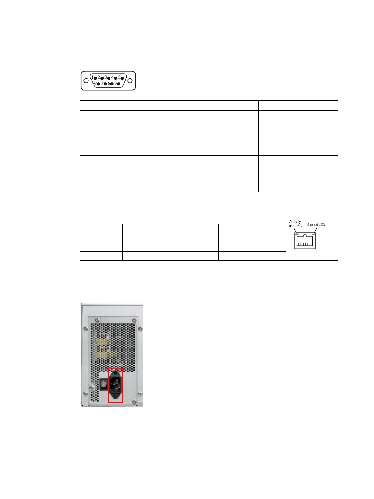
Pin assignment for COM port 1 and 2
Pin
RS-232
RS-422
RS-485
1
DCD
422TX-
485TX-/485RX-
2
RXD
422RX+
4
DTR
422RX-
5 GND
GND
GND
6
DSR
7
RTS
8
CTS
9
RI
LAN port LED indications
Activity Link LED
Speed LED
Status
Description
Status
Description
Off
no link established
Off
link speed 10Mbps
Blink
transferring data
Green
link speed 1Gbps
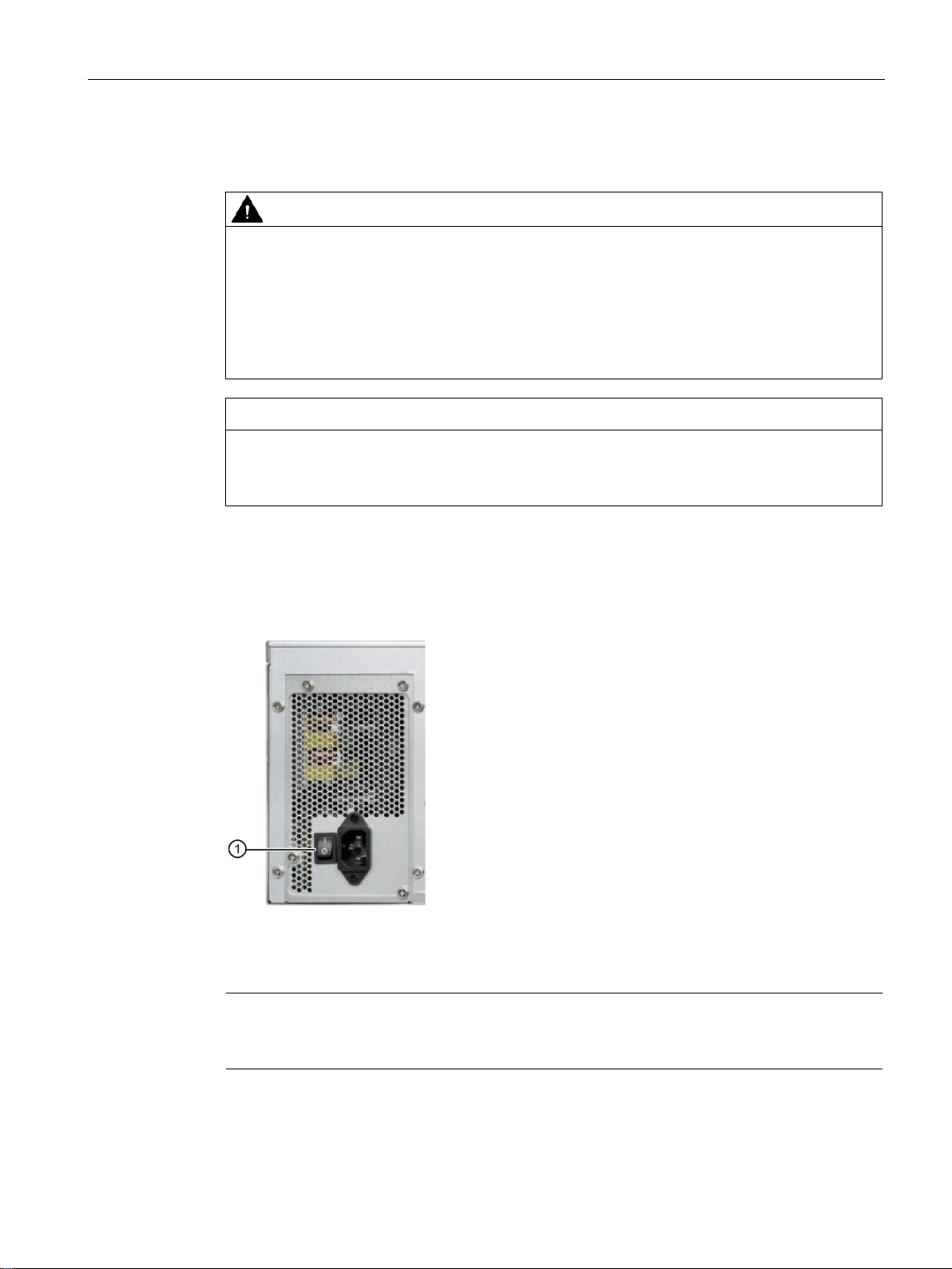
Power supply
1.2 Design of the device
3 TXD 422TX+ 485TX+/485RX+
Orange link established Red link speed 100Mbps
The following figure shows the connector for the IPC347E power supply.
SIMATIC IPC347E
14 Operating Ins tructions, 09/2018, A5E41134132-AE
Overview
1.2.2
Operator controls
WARNING
No mains disconnection
NOTICE
Make sure the disconnect devices main readily operable.
The MAINS plug or an appliance coupler of the apparatus is used as the disconnect device,
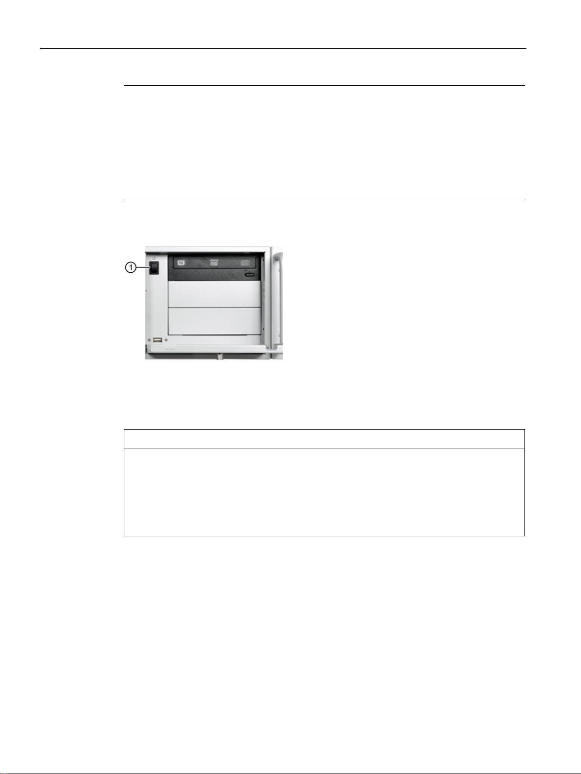
On/off switch
①
On/off switch
On/off button
Note
The on/off button is only effective when the power supply is switched on via the on/off switch
at the rear of the dev
1.2 Design of the device
The on/off button and on/off switch do not disconnect the device from the mains.
In the case of damage to the device, connecting cables or improper opening of the device,
there is a risk of fire and electric shock.
Always pull out the power plug when the device is not in use. Disconnect the device from
the network by additional measures, for example, with an isolating switch.
the disconnect device shall remain readily operable.
The following figure shows the location of the on/off switch.
ice.
SIMATIC IPC347E
Operating Instructions, 09/2018, A5E41134132-AE
15
Overview
Note
The PC switches on automatically after the power recovers when "Power Failure Recovery"
is active.
Depending on the
automatically or you must press the on/off button on the front. T
becomes effective when the device is without mains voltage for at least 10 seconds.
Automatic startup may endanger the operation of the machine or plant, for example, after a
power failure. Take this into account when designing the pla
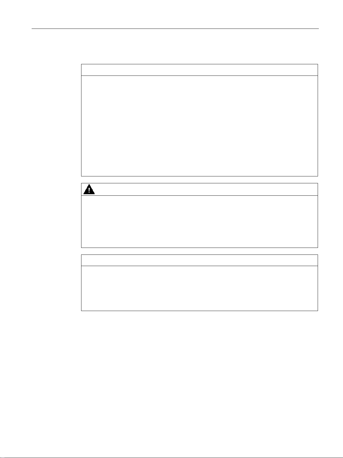
The on/off/reset button
•
•
•
1
You can set this operation as shut down, sleep or hibernate in operating system.
NOTICE
Data loss
1.2 Design of the device
"Power Failure Recovery" setting in BIOS, the PC switches on
he BIOS setting only
nt.
The following figure shows the position of the on/off button at the front of the device.
① has three functions:
Switch on the PC, press the on/off button once
shortly.
Shut down the operating system and switch off
PC, press the on/off button once shortly.
Switch off PC without shutting down the
operating system, press for more than 4
seconds – hardware reset.
1
If the device is restarted by hardware reset, data in the main memory is deleted and the
data on the hard disk drive may be lost.
Perform a hardware reset only in the case of an emergency. Close all running programs.
Make sure that there is no more read or write access to drives and I/O before performing
the hardware reset.
SIMATIC IPC347E
16 Operating Ins tructions, 09/2018, A5E41134132-AE

2
2.1
Security information
Siemens provides products and solutions with industrial security functions that support the
secure operation of plants, systems, machines and networks.
In order to protect plants, systems, machines and networks against cyber threats, it is
necessary to implement – and continuously maintain – a holistic, state-of-the-art industrial
security concept. Siemens' products and solutions constitute one element of such a concept.
Customers are responsible for preventing unauthorized access to their plants, systems,
machines and networks. Such systems, machines and components should only be
connected to an enterprise network or the internet if and to the extent such a connection is
necessary and only when appropriate security measures (e.g. firewalls and/or network
segmentation) are in place.
For additional information on industrial security measures that may be implemented, please
visit (https://www.siemens.com/industrialsecurity).
Siemens' products and solutions undergo continuous development to make them more
secure. Siemens strongly recommends that product updates are applied as soon as they are
available and that the latest product versions are used. Use of product versions that are no
longer supported, and failure to apply the latest updates may increase customers' exposure
to cyber threats.
To stay informed about product updates, subscribe to the Siemens Industrial Security RSS
Feed under (https://www.siemens.com/industrialsecurity).
SIMATIC IPC347E
Operating Instructions, 09/2018, A5E41134132-AE
17

Safety instructions
2.2
General safety instructions
Fully disconnecting the device from mains voltage
WARNING
Risk of fire and electric shock
shock and fire hazard, for example, if the device or connection cables are damaged or if the
If the device is mounted in a control cabinet: Shut down the operating system and switch
Devices in the control cabinet
WARNING
Life-threatening voltages are present with an open control cabinet
2.2 General safety instructions
The on/off button and on/off switch do not fully disconnect the device from the main power
supply. If the device is switched off with the on/off switch, there remains a risk of electric
device is used improperly.
Always completely disconnect the device from the main power supply as follows before
performing work on the device or when the device will not be used over an extended period
of time.
• If the device is not mounted in a control cabinet: Shut down the operating system and
pull the power plug on the rear of the device.
•
the AC circuit breaker to "Off".
• Properly connect the device to a protective conductor.
When you open the control cabinet, some areas or components might be carrying lifethreatening voltages.
If you touch these areas or components, electric shock might kill you.
Switch off the power supply to the cabinet before opening it.
SIMATIC IPC347E
18 Operating Ins tructions, 09/2018, A5E41134132-AE
Safety instructions
System expansions
NOTICE
Damage to the device, machine or plant due to device and system expansions
stem expansions and damage
CAUTION
Fire hazard due to overheating of the device
NOTICE
Open Equipment
2.2 General safety instructions
Device and system expansions may contain faults and affect the entire device, machine or
plant.
Device and system expansions may violate safety rules and regulations regarding radio
interference suppression. If you install or replace device or sy
your device, the warranty is voided.
Note the following:
• Only install device or system expansions designed for this device. Contact your
technical support team or the point of sale to find out which device and system
expansions are suitable for installation.
• Please observe the information on electromagnetic compatibility in the technical
specifications.
Expansion cards generate additional heat. The device can overheat or cause a fire.
• Observe the safety and installation instructions for the expansion cards.
• If necessary, install the device in an enclosure that meets the requirements of
paragraphs 4.6 and 4.7.3 of the standards EN 60950-1:2006 and IEC/UL/EN/DIN-EN
60950-1.
When the device is used in the area of Industrial Control Equipment in accordance with
UL61010-2-201, the device is classified as "Open equipment".
Open equipment must be installed within an enclosure which protects you from hazards,
including mechanical hazards, electrical shock and spread of fire.
SIMATIC IPC347E
Operating Instructions, 09/2018, A5E41134132-AE
19

Safety instructions
Battery
WARNING
Risk of explosion and release of harmful substances
High frequency radiation
NOTICE
Unintentional operating situations
High frequency radiation, e.g. from a cellular phone, may interfere with device functions and
2.2 General safety instructions
Improper handling of lithium batteries can result in an explosion of the batteries.
Explosion of lithium batteries and the released pollutants can cause serious physical injury.
Damaged batteries jeopardize the function of the device.
Note the following when handling lithium batteries:
• Replace used batteries in good time.
• Replace the lithium battery only with the type recommended by the manufactory. For
detailed information, refer to the section "Replacing the backup battery (Page 56)" in the
operating instructions.
• For any requirements on product maintenance, contact Siemens Technical support
(Page 123).
• Do not throw lithium batteries into fire, do not solder on the cell body, do not recharge,
do not open, do not short-circuit, do not reverse polarity, do not heat above 100°C and
protect from direct sunlight, moisture and condensation.
can cause malfunctions resulting in personal injury or material damage.
Avoid high-frequency radiation:
• Remove radiation sources from the environment of the device.
• Switch off radiating devices.
• Reduce the radio output of radiating devices.
• Please observe the information on electromagnetic compatibility in the technical
specifications.
SIMATIC IPC347E
20 Operating Ins tructions, 09/2018, A5E41134132-AE
Safety instructions
ESD directive
NOTICE
Electrostatic sensitive devices (ESD)
s
2.3
Headphones
CAUTION
Impaired hearing due to excessive sound pressure
CAUTION
Protection against access by unauthorized persons
2.3 Headphones
Electrostatic sensitive devices can be labeled with an appropriate symbol.
When you touch electrostatic sensitive components, you can destroy them through voltage
that are far below the human perception threshold.
If you work with components that can be destroyed by electrostatic discharge, observe the
ESD directive in the technical specifications.
The setting of the volume and the equalizer can increase the sound pressure in the
headphones. Other factors not mentioned by the manufacturer can also influence the
sound pressure, for example, the operating system, equalizer software, firmware and
driver.
Excessive sound pressure from headphones can result in impaired hearing or even loss of
hearing.
Set the volume control and equalizer to the lowest value before you put on the
headphones. Keep checking the volume control setting. Only use headphones and
software approved by the manufacturer.
An unauthorized user can operate the device incorrectly and bypass logon by restarting the
device.
Operator actions by unauthorized persons jeopardize operational reliability.
Take the following safety precautions:
• Lock the front panel cover.
• Do not use keyboards with an on/off button (Power button).
• If the device has an on/off button, assign the parameters of the function of the on/off
button to meet your requirements under Windows. You can find the settings in the
"Power Options" menu.
SIMATIC IPC347E
Operating Instructions, 09/2018, A5E41134132-AE
21

Safety instructions
2.4
Notes on use
Possible functional restrictions in case of non-validated plant operation
NOTICE
2.4 Notes on use
The device is tested and certified on the basis of the technical standards. In rare cases,
functional restrictions can occur during plant operation.
Validate the correct functioning of the plant to avoid functional restrictions.
Rack-mount instructions
A) Elevated Operating Ambient - If installed in a closed or multi-unit rack, the operating
ambient temperature of the rack environment may be greater than the room ambient.
Therefore consideration should be given to installing the equipment in an environment
compatible with the maximum ambient temperature (Tma) specified by the manufacturer.
B) Reduced Air Flow - Installation of the equipment in a rack should be such that the
amount of air flow required for safe operation of the equipment is not compromised.
C) Mechanical Loading - Mounting of the equipment in the rack should be such that a
hazardous condition is not achieved due to uneven mechanical loading.
D) Circuit Overloading - Consideration should be given to the connection of the equipment
to the supply circuit and the effect that overloading of the circuits might have on overcurrent
protection and supply wiring. Appropriate consideration of equipment nameplate ratings
should be used when addressing this concern.
E) Reliable Earthing - Reliable earthing of rack-mounted equipment should be maintained.
Particular attention should be given to supply connections other than direct connections to
the branch circuit (e. g. use of power strips).
SIMATIC IPC347E
22 Operating Ins tructions, 09/2018, A5E41134132-AE
Safety instructions
CAUTION
Ambient conditions
WARNING
Risk of electric shock when using a power connection without earth connection
Note
Use in an industrial environment without additional protective measures
This device was designed for use in a normal industrial env
IEC
2.4 Notes on use
Ambient conditions for which the device is not suitable can cause faults or damage the
device.
Note the following:
• This device could malfunction if operated in close proximity to wireless communication
devices, such as a mobile phone, Wi-Fi or Bluetooth device.
• The MAINS plug or an appliance coupler of the device is used as the disconnect device,
the disconnect device shall remain readily operable.
• Operate the device only in closed rooms. Failure to comply nullifies the warranty.
• Do not put anything on top of the device.
• To reduce the risk of fire or electric shock, do not expose this product to rain or
moisture.
• Device shall not be exposed to dripping or splashing and no objects filled with liquids,
such as vases, shall be placed on the device.
• Operate the device only in accordance with the ambient conditions specified in the
technical specifications.
• Do not expose the device to direct sunlight or other strong sources of light.
• Without additional measures, such as a supply of clean air, the device may not be used
in locations with harsh operating conditions caused by acidic vapors or gases.
• Protect the device against dust, moisture and heat.
• Observe the permitted mounting positions of the device.
• Do not obstruct the venting slots of the device.
Using a mains cable without proper earth connection can result in personal injury or even
death by electric shock. A mains cable is not included with IPC347E. Make sure the cable
you use provides a proper earth connection.
It is highly recommended that you use a mains cable from SIEMENS.
60721-3-3.
SIMATIC IPC347E
Operating Instructions, 09/2018, A5E41134132-AE
ironment according to
23

Safety instructions
2.4 Notes on use
SIMATIC IPC347E
24 Operating Ins tructions, 09/2018, A5E41134132-AE

3
3.1
Preparing for installation
3.1.1
Checking the delivery package
Procedure
NOTICE
Damage to the device during transport and storage
1. When you receive a delivery, inspect the packaging for visible transport damage.
2. In case of any transport damage, turn to the shipping company in charge. Have the
forwarder confirm the transport damage immediately.
3. Unpack the device at its installation location.
4. Keep the original packaging in case you have to transport the unit again.
If a device is transported or stored without packaging, shocks, vibrations, pressure and
moisture might impact the unprotected device. A damaged packaging indicates that
ambient conditions have already had an impact the device.
The device might be damaged.
Do not dispose of the original packaging. Pack the device when it needs to be
transported or stored.
5. Inspect the contents of the packaging and all the accessories you ordered. Make sure
that they are complete and not damaged.
SIMATIC IPC347E
Operating Instructions, 09/2018, A5E41134132-AE
25

Installing and connecting the device
WARNING
Electric shock and fire hazard due to damaged device
NOTICE
Damage from condensation
3.1.2
Device identification data
Rating plate
3.1 Preparing for installation
6. If the contents of the packaging are incomplete, damaged or do not match with your
order, inform our service department or the sales representative who deliver you the
product immediately.
A damaged device can be under hazardous voltage and trigger a fire in the machine or
the plant. A damaged device has unpredictable properties and states.
Death or serious injury could occur.
Make sure that the damaged device is not inadvertently installed and put into operation.
If the device is subjected to low temperatures or extreme fluctuations in temperature
during the transportation, for example in cold weather, moisture could condensed on or
inside the device.
Moisture can result in short-circuits and damage the device.
In order to prevent damage to the device, observe the following rules:
If a condensation happens, wait approximately 12 hours or until the device is completely
dry before switching it on.
7. Keep the enclosed documentation in a safe place. You need the documentation when
you commission the device for the first time or meet other problems in the later work.
8. Record the identification data of the device.
The device can be clearly identified with the help of this identification data in case of repairs
or loss.
The following illustrations are examples. The data of your device may differ from the data in
these examples.
The rating plate is located on the inside of the front door for the SIMATIC IPC347E.
SIMATIC IPC347E
26 Operating Ins tructions, 09/2018, A5E41134132-AE

Installing and connecting the device
Identification data
Where is it?
④
COA label
Component label
Identification data
Where is it?
⑤
3.1 Preparing for installation
The rating plate of the SIMATIC IPC347E is shown below.
Order number
Serial number
Product version
Unified Siemens address for
product liability
①
②
③
The COA label (Certificate of Authenticity) is only provided with a pre-installed Windows
operating system. Open the front door to check for the COA label.
SIMATIC IPC347E
Operating Instructions, 09/2018, A5E41134132-AE
The component label is located inside the front door.
Ethernet address 1,
MAC address
Ethernet address 2,
MAC address
⑥
Normally, ⑥=⑤+1. For example, If
MAC address 1 is C0-D9-62-10-D0-A5,
MAC address 2 is C0-D9-62-10-D0-A6.
27

Installing and connecting the device
Procedure
Identification date
Source
Value
Order number
Rating plate
6AG4012-1 ...
Manufacturing version
Rating plate
FS
Microsoft Windows Product Key
COA label
Component label
⑤
3.2
Installing the device
3.2.1
Installation information
NOTICE
Risk of fire
Note
If the equipment is used in a manner not specified by the manufacture, the protection
provided by the equipment m
3.2 Installing the device
Serial number Rating plate s XXX 1234...
Ethernet address 1, MAC address BIOS setup > "Main" menu
Ethernet address 2, MAC address
or:
⑥
1. Copy the order number, serial number and manufacturing version in the table listed
above.
2. Copy the Windows "Product Key" to the table.
3. Copy the Ethernet addresses from the component label to the table.
The Ethernet addresses can also be found in the BIOS setup (F2 key) under "Main >
System Information", entries "LAN 1 MAC" and "LAN 2 MAC".
If you install the device in an unapproved mounting position or if you do not observe the
ambient conditions, the device can overheat. Conformity with the low voltage directive
becomes void.
Device overheating can cause a fire. Proper functioning of the device is no longer
guaranteed.
Before you install the device, note the following general installation information.
ight be impaired.
SIMATIC IPC347E
28 Operating Instructions, 09/2018, A5E41134132-AE

Installing and connecting the device
3.2.2
Mounting location and position
Optional mounting locations
3.2 Installing the device
● The device is approved for indoor operation only.
● When the device is used in the area of Industrial Control Equipment in accordance with
UL61010-2-201, the device is classified as "Open equipment".
Open equipment must be installed within an enclosure which protects you from hazards,
including mechanical hazards, electrical shock and spread of fire.
● Install the device only in one of the described permitted mounting positions.
● For installation of control cabinet, observe the country-specific regulations.
● Provide adequate volume in the switchgear cabinet for air circulation and heat transport.
Keep at least 10 cm between the device and the switchgear cabinet.
● Do not cover the vent slots of the device.
● Ensure that the maximum air intake temperature, measured 5 cm before the air intake
opening, does not exceed 40° C. The maximum air intake temperature must be
accounted for especially when sizing closed switchgear cabinets.
● The minimum distance between the device and the housing is 10 cm on the air output
end.
● Ensure that the installed device does not pose a danger, for example, hit someone by
falling over.
● All the external circuit of the device must be SELV circuit.
The device can be mounted horizontally in control desks and 19" rack systems.
SIMATIC IPC347E
Operating Instructions, 09/2018, A5E41134132-AE
29
Installing and connecting the device
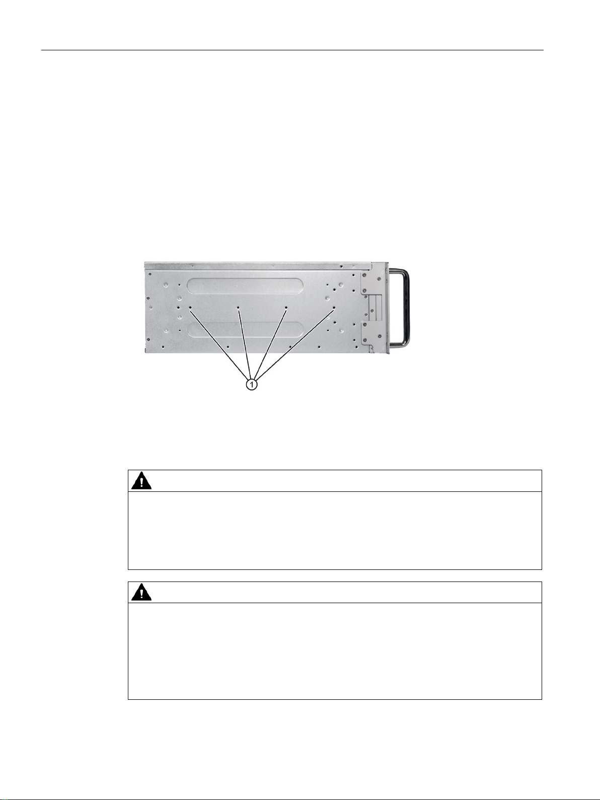
Possible mounting positions
①
Threaded holes for 3A68
WORKS CO., LTD or other telescopic rails match the dimensional and technical r
quirements.
CAUTION
Risk of short-circuit and electric shock
CAUTION
Risk of physical injury
3.2 Installing the device
You can mount the device as follows:
● Mounting with mounting brackets, horizontal
● Mounting on device bases, horizontal
● Mounting on telescopic rails
When telescopic rails are used for mounting, the device can be withdrawn fully from the
cabinet or rack. For detailed information on telescopic rails, see the sections "Technical
specifications of the telescopic rails (Page 80)" and "Dimensional drawing for the use of
telescopic rails (Page 74)".
The figure below shows the position of the mounting holes for angle brackets or
telescopic rails.
-508 R&L telescopic rails from the company KING SLIDE
e-
Some small widget or water may drop into the device from the holes in the rear of the
device.
Make sure the rear cover of device is vertical to the ground after mounted. Don't put
anything filled with liquid on top of the device.
The device is too heavy to be mounted exclusively with the 19-inch brackets of the front
panel.
The device may fall down, injure people and get damaged.
Secure the device using additional measures. The mounting screws of the telescopic rails
may not protrude more than 5 mm into the device.
SIMATIC IPC347E
30 Operating Ins tructions, 09/2018, A5E41134132-AE
 Loading...