

Siemens SIMATIC IPC327E Operating Instructions Manual

SIMATIC IPC327E
SIMATIC
Industrial PC
SIMATIC IPC327E
Operating Instructions
06/2019
A5E40965257
Preface
Overview
1
Safety instructions
2
Installing and connecting the
device
3
Commissioning the device
and device functions
4
Expanding and assigning
parameters to the device
5
Maintaining and repairing the
device
6
Technical specifications
7
Appendix Motherboard
A
Technical support
B
Markings and symbols
C
List of abbreviations
D
-AD

Siemens AG
Division Digital Factory
Postfach 48 48
90026 NÜRNBERG
GERMANY
A5E40965257-AD
Ⓟ
Copyright © Siemens AG 2019.
All rights reserved
Legal information
Warning notice system
DANGER
indicates that death or severe personal injury will result if proper precautions are not taken.
WARNING
indicates that death or severe personal injury may result if proper precautions are not taken.
CAUTION
indicates that minor personal injury can result if proper precautions are not taken.
NOTICE
indicates that property damage can result if proper precautions are not taken.
Qualified Personnel
personnel qualified
Proper use of Siemens products
WARNING
Siemens products may only be used for the applications described in the catalog and in the relevant technical
ambient conditions must be complied with. The information in the relevant documentation must be observed.
Trademarks
Disclaimer of Liability
This manual contains notices you have to observe in order to ensure your personal safety, as well as to prevent
damage to property. The notices referring to your personal safety are highlighted in the manual by a safety alert
symbol, notices referring only to property damage have no safety alert symbol. These notices shown below are
graded according to the degree of danger.
If more than one degree of danger is present, the warning notice representing the highest degree of danger will
be used. A notice warning of injury to persons with a safety alert symbol may also include a warning relating to
property damage.
The product/system described in this documentation may be operated only by
task in accordance with the relevant documentation, in particular its warning notices and safety instructions.
Qualified personnel are those who, based on their training and experience, are capable of identifying risks and
avoiding potential hazards when working with these products/systems.
Note the following:
documentation. If products and components from other manufacturers are used, these must be recommended
or approved by Siemens. Proper transport, storage, installation, assembly, commissioning, operation and
maintenance are required to ensure that the products operate safely and without any problems. The permissible
All names identified by ® are registered trademarks of Siemens AG. The remaining trademarks in this publication
may be trademarks whose use by third parties for their own purposes could violate the rights of the owner.
We have reviewed the contents of this publication to ensure consistency with the hardware and software
described. Since variance cannot be precluded entirely, we cannot guarantee full consistency. However, the
information in this publication is reviewed regularly and any necessary corrections are included in subsequent
editions.
for the specific
07/2019 Subject to change

Preface
Basic knowledge requirements
Scope of validity of this document
Scope of this documentation
Conventions
These operating instructions contain all the information you need for commissioning and
operation of the SIMATIC IPC327E.
It is intended both for programming and testing personnel who commission the device and
connect it with other units (automation systems, programming devices), as well as for service
and maintenance personnel who install add-ons or carry out fault/error analyses.
A solid background in personal computers and Microsoft operating systems is required to
understand this manual. General knowledge in the field automation control engineering is
recommended.
These operating instructions are valid for all versions of the SIMATIC IPC327E.
The documentation for the SIMATIC IPC327E consists of:
● Product information, e.g. "Important notes on your device"
● Quick Install Guide SIMATIC IPC327E
● SIMATIC IPC327E operating instructions in English and Chinese
The PDF version of the documentation is supplied with the device on the
"Documentation and Drivers" CD/DVD.
The terms "PC" and "device" are sometimes used to refer to the SIMATIC IPC327E in this
documentation.
In these operating instructions, the abbreviation "Windows 7" denotes the term
"Windows 7 Ultimate".
SIMATIC IPC327E
Operating Instructions, 06/2019, A5E40965257-AD
3

Preface
History
Edition
Comment
08/2017
First edition
system documents.
07/2018
Amendment to certification part.
The following editions of these operating instructions have been published:
11/2017 Operating system information has been replaced by references to separate operating
06/2019 Update the Advanced menu for BIOS description.
SIMATIC IPC327E
4 Operating Instructions, 06/2019, A5E40965257-AD

Table of contents
Preface ................................................................................................................................................... 3
1 Overview................................................................................................................................................. 8
2 Safety instructions ................................................................................................................................. 12
3 Installing and connecting the device ...................................................................................................... 16
4 Commissioning the device and device functions .................................................................................... 29
5 Expanding and assigning parameters to the device ............................................................................... 33
6 Maintaining and repairing the device ..................................................................................................... 37
1.1 Product description ................................................................................................................... 8
1.2 Structure of the devices ............................................................................................................ 9
1.2.1 Views of the basic device ......................................................................................................... 9
1.2.2 Interfaces of the basic device ................................................................................................. 10
1.2.3 Status displays ........................................................................................................................ 11
2.1 Security information ................................................................................................................ 12
2.2 General safety instructions ..................................................................................................... 12
2.3 Notes on use ........................................................................................................................... 15
3.1 Preparing for installation ......................................................................................................... 16
3.1.1 Checking the delivery package ............................................................................................... 16
3.1.2 Identification data of the device .............................................................................................. 17
3.1.3 Permitted mounting positions ................................................................................................. 19
3.2 Mounting the device ................................................................................................................ 20
3.2.1 Mounting instructions .............................................................................................................. 20
3.2.2 Mounting on a standard rail .................................................................................................... 22
3.2.3 Wall mounting ......................................................................................................................... 24
3.3 Connecting the device ............................................................................................................ 24
3.3.1 Notes on connecting ............................................................................................................... 24
3.3.2 Connecting the function earth ................................................................................................. 25
3.3.3 Connecting the power supply ................................................................................................. 26
3.3.4 Connect device to networks .................................................................................................... 27
4.1 General information on commissioning .................................................................................. 29
4.2 Initial commissioning ............................................................................................................... 29
4.3 Switching off the device .......................................................................................................... 31
4.4 Windows Security Center ....................................................................................................... 32
5.1 Open the device ...................................................................................................................... 33
5.2 Installing the Mini card ............................................................................................................ 34
6.1 Maintenance ........................................................................................................................... 37
SIMATIC IPC327E
Operating Instructions, 06/2019, A5E40965257-AD
5

Table of contents
7 Technical specifications ........................................................................................................................ 45
A Appendix Motherboard .......................................................................................................................... 76
6.2 Repair information .................................................................................................................. 37
6.3 Recycling and disposal .......................................................................................................... 38
6.4 Installing and removing hardware .......................................................................................... 39
6.4.1 Replacing the backup battery ................................................................................................ 39
6.4.2 Replacing the drive of a basic device .................................................................................... 40
6.5 Installing the software ............................................................................................................ 41
6.5.1 Installing the drivers ............................................................................................................... 42
7.1 Certificates and approvals ..................................................................................................... 45
7.2 Directives and declarations .................................................................................................... 47
7.2.1 Electromagnetic compatibility, Industrial and Residential Areas ........................................... 47
7.2.2 ESD guideline ........................................................................................................................ 48
7.3 Dimension drawings ............................................................................................................... 50
7.3.1 Dimension drawing basic device............................................................................................ 50
7.4 Technical data ........................................................................................................................ 51
7.4.1 General technical specifications ............................................................................................ 51
7.4.2 Environmental conditions ....................................................................................................... 53
7.4.3 Power demand of the components ........................................................................................ 54
7.4.4 DC power supply .................................................................................................................... 55
7.5 Hardware descriptions ........................................................................................................... 55
7.5.1 Technical features of the motherboard .................................................................................. 55
7.5.2 External interfaces ................................................................................................................. 56
7.5.2.1 Overview of interfaces ........................................................................................................... 56
7.5.2.2 DC in connector ..................................................................................................................... 56
7.5.2.3 Serial interface ....................................................................................................................... 56
7.5.2.4 USB 2.0 port ........................................................................................................................... 58
7.5.2.5 USB 3.0 port ........................................................................................................................... 58
7.5.2.6 DisplayPort ............................................................................................................................. 58
7.5.2.7 Ethernet port .......................................................................................................................... 59
7.5.3 Internal interfaces................................................................................................................... 60
7.5.3.1 Overview of internal interfaces ............................................................................................... 60
7.5.3.2 Mini PCIe and mSATA interface ............................................................................................ 60
7.5.4 Currently allocated system resources .................................................................................... 61
7.6 BIOS description .................................................................................................................... 61
7.6.1 BIOS getting started ............................................................................................................... 61
7.6.2 Main setup .............................................................................................................................. 63
7.6.3 Advanced setup ..................................................................................................................... 64
7.6.4 Chipset setup ......................................................................................................................... 68
7.6.5 Security setup ........................................................................................................................ 69
7.6.6 Boot Setup ............................................................................................................................. 71
7.6.7 Save and Exit ......................................................................................................................... 74
A.1 Jumpers ................................................................................................................................. 76
SIMATIC IPC327E
6 Operating Instructions, 06/2019, A5E40965257-AD

Table of contents
B Technical support .................................................................................................................................. 79
C Markings and symbols .......................................................................................................................... 82
D List of abbreviations .............................................................................................................................. 85
Glossary ............................................................................................................................................... 89
Index..................................................................................................................................................... 97
B.1 Service and support ................................................................................................................ 79
B.2 Troubleshooting ...................................................................................................................... 80
B.3 Notes on the use of third-party modules ................................................................................. 81
C.1 Overview ................................................................................................................................. 82
C.2 Safety ...................................................................................................................................... 82
C.3 Operator controls .................................................................................................................... 82
C.4 Certificates, approvals and markings ...................................................................................... 83
C.5 Interfaces ................................................................................................................................ 84
SIMATIC IPC327E
Operating Instructions, 06/2019, A5E40965257-AD
7
1
1.1
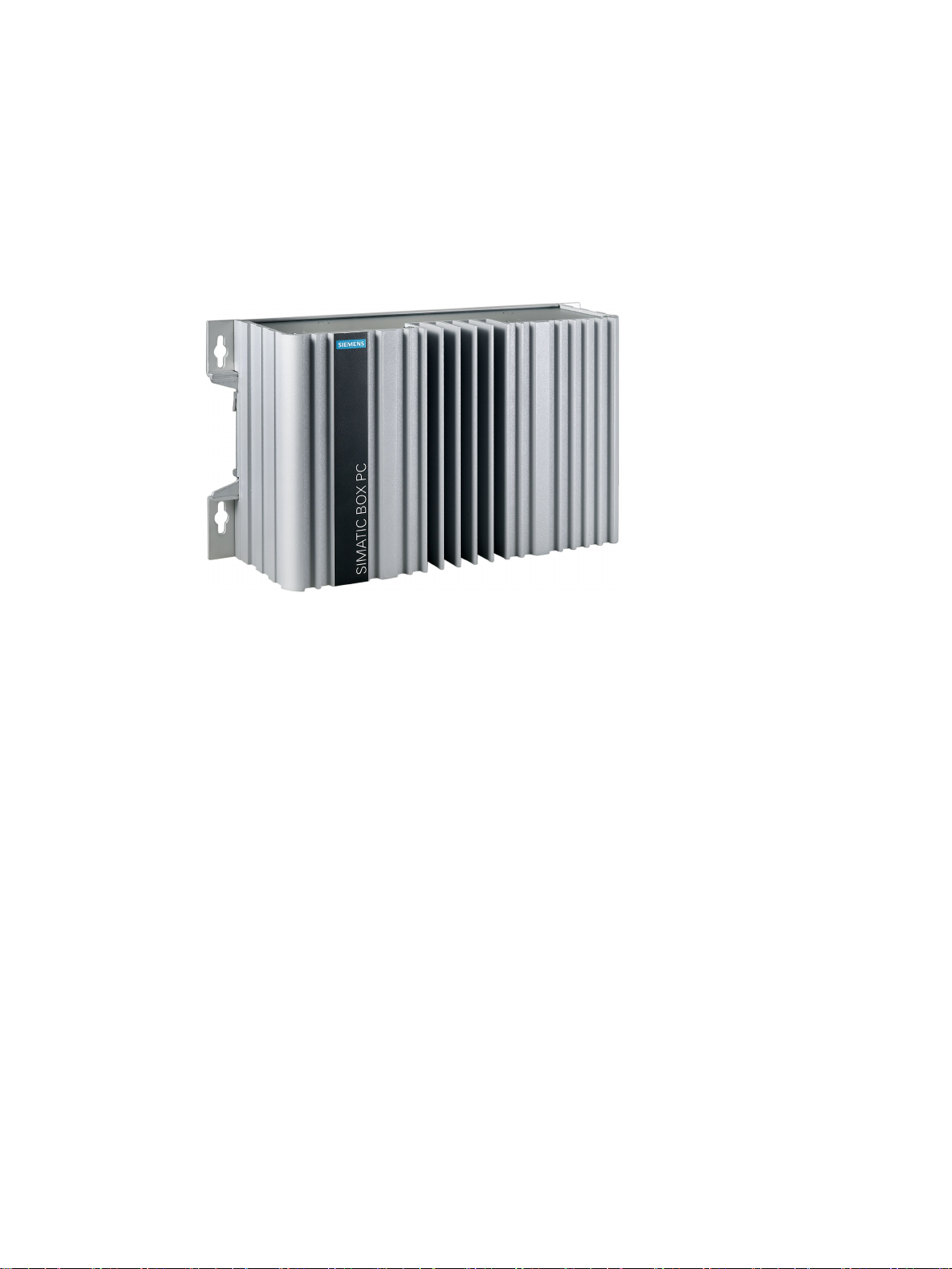
Product description
SIMATIC IPC327E provides industrial functionality.
● Compact design
● Fanless
● Various interfaces
● IP40 protection
SIMATIC IPC327E
8 Operating Instructions, 06/2019, A5E40965257-AD
Overview
1.2
Structure of the devices
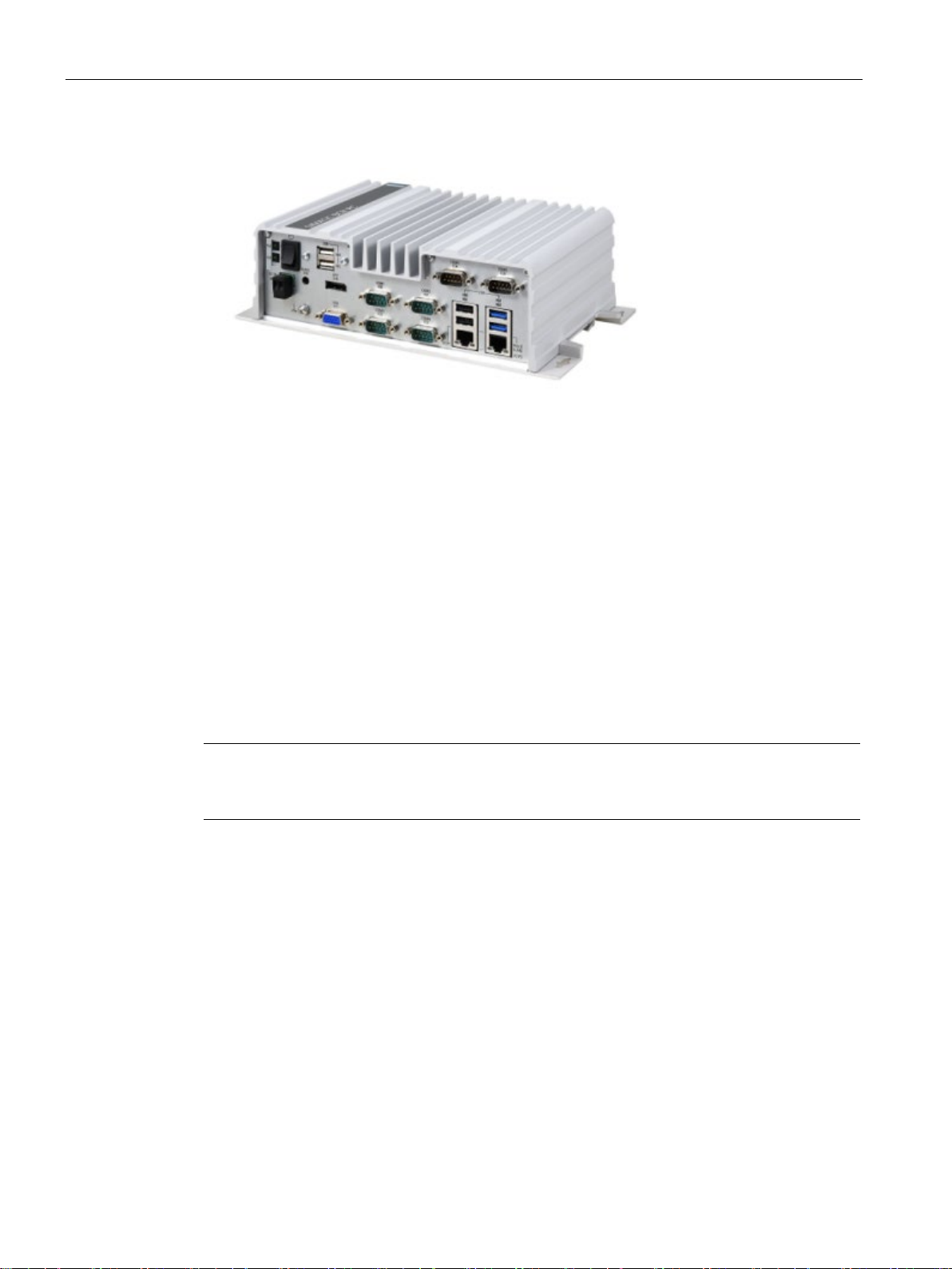
1.2.1
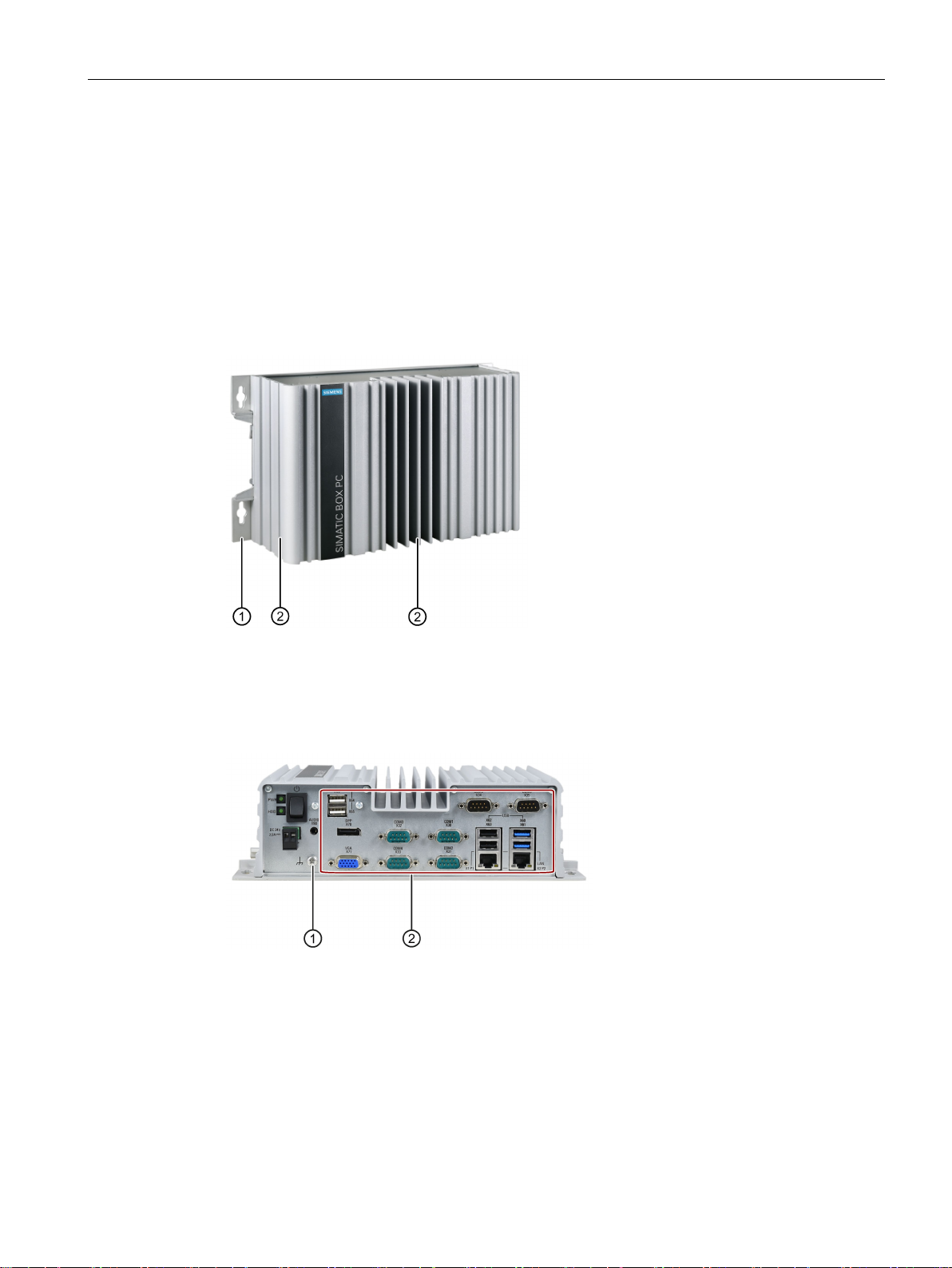
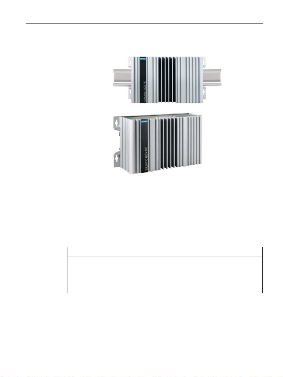
Views of the basic device
Front view and side view
①
Mounting holes for wall mounting
②
Cooling fins
Bottom view
①
Function earth
②
Ports
1.2 Structure of the devices
The front view as below is the standard mounting position.
SIMATIC IPC327E
Operating Instructions, 06/2019, A5E40965257-AD
9
Overview
1.2.2
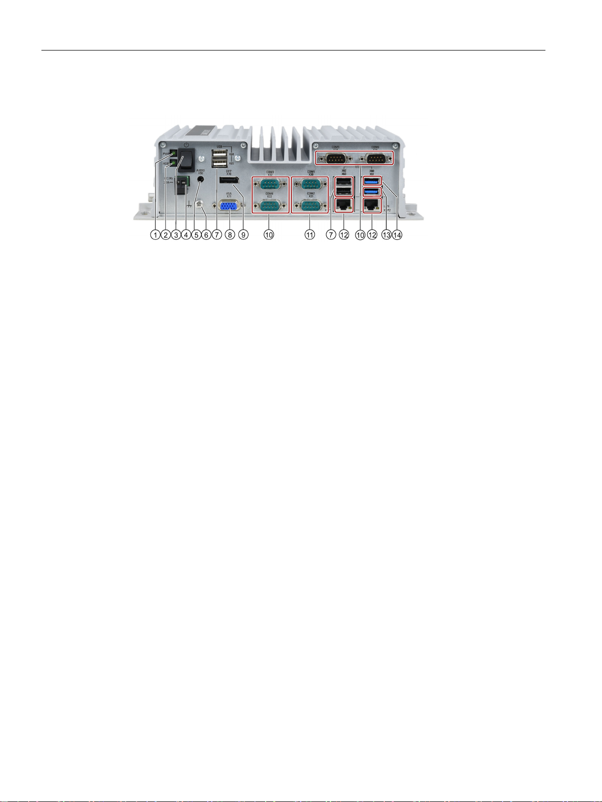
Interfaces of the basic device
①
Power status display
②
HDD status display
③
On/off switch
④
Connection for a 24 VDC power supply
⑤
Connection for analog audio source and speaker.
⑥
Function earth
⑦
USB
⑧
VGA interface
⑨
DisplayPort connection
⑩
Serial interface, 9
•
⑪
Serial interface, 9
•
•
•
⑫
RJ45 Ethernet connection for 10/100/1000 Mbps
⑬
USB 3.0 port 2, high current
⑭
USB 3.0 port 1, high current
1.2 Structure of the devices
2.0, high current
-pin
RS-232
-pin
RS-232
RS-422
RS-485
SIMATIC IPC327E
10 Operating Instructions, 06/2019, A5E40965257-AD
Overview
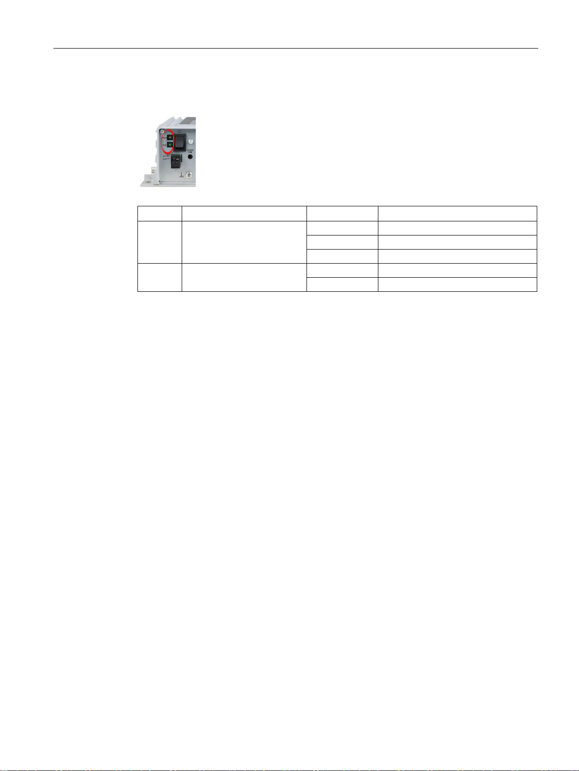
1.2.3
Status displays
Display
Meaning
LED
Description
Off
Hibernate, switched off or unplugged
Green
PC is in operation.
Green flashing
standby
Off
No accessing
Green flashing
Accessing data
1.2 Structure of the devices
PWR PC operating status display
HDD Display for hard disk access
SIMATIC IPC327E
Operating Instructions, 06/2019, A5E40965257-AD
11

2
2.1
Security information
2.2
General safety instructions
WARNING
Life-threatening voltages are present with an open control cabinet
Siemens provides products and solutions with industrial security functions that support the
secure operation of plants, systems, machines and networks.
In order to protect plants, systems, machines and networks against cyber threats, it is
necessary to implement – and continuously maintain – a holistic, state-of-the-art industrial
security concept. Siemens’ products and solutions constitute one element of such a concept.
Customers are responsible for preventing unauthorized access to their plants, systems,
machines and networks. Such systems, machines and components should only be
connected to an enterprise network or the internet if and to the extent such a connection is
necessary and only when appropriate security measures (e.g. firewalls and/or network
segmentation) are in place.
For additional information on industrial security measures that may be implemented, please
visit (https://www.siemens.com/industrialsecurity).
Siemens' products and solutions undergo continuous development to make them more
secure. Siemens strongly recommends that product updates are applied as soon as they are
available and that the latest product versions are used. Use of product versions that are no
longer supported, and failure to apply the latest updates may increase customers' exposure
to cyber threats.
To stay informed about product updates, subscribe to the Siemens Industrial Security RSS
Feed visit (https://www.siemens.com/industrialsecurity).
When you install the device in a control cabinet, some areas or components in the open
control cabinet may be carrying life-threatening voltages.
If you touch these areas or components, you may be killed by electric shock.
Switch off the power supply to the cabinet before opening it.
SIMATIC IPC327E
12 Operating Instructions, 06/2019, A5E40965257-AD
Safety instructions
System expansions
NOTICE
Damage through system expansions
WARNING
Risk of fire through expansion cards
NOTICE
"Open Type" UL61010-2-201
2.2 General safety instructions
Device and system expansions may be faulty and can affect the entire machine or plant.
The installation of expansions can damage the device, machine or plant. Device and
system expansions may violate safety rules and regulations regarding radio interference
suppression. If you install or exchange system expansions and damage your device, the
warranty becomes void.
Note the following for system expansions:
● Only install system expansion devices designed for this device. Contact your technical
support team or where you purchased your PC to find out which system expansion
devices may safely be installed.
● Observe the information on electromagnetic compatibility (Page 47).
Expansion cards generate additional heat. The device may overheat and cause a fire.
Please note the following:
• Observe the safety and installation instructions for the expansion cards.
• If in doubt, install the device in an enclosure that is compliant with sections 4.6 and 4.7.3
of the IEC/UL/EN/DIN-EN 60950-1 standard.
Note that the device is classified as "Open Type" for use in the area of Industrial Control
Equipment (UL61010-2-201). A UL61010-2-201 conform enclosure is therefore a
mandatory requirement for approval or operation according to UL61010-2-201.
SIMATIC IPC327E
Operating Instructions, 06/2019, A5E40965257-AD
13
Safety instructions
Battery
WARNING
Risk of explosion and release of harmful substances
Strong high-frequency radiation
NOTICE
Observe immunity to RF radiation
ESD Guideline
NOTICE
Electrostatic sensitive devices (ESD)
When you touch electrostatic sensitive components, you can destroy them through voltages
2.2 General safety instructions
Improper handling of lithium batteries can result in an explosion of the batteries.
Explosion of the batteries and the released pollutants can cause severe physical injury.
Worn batteries jeopardize the function of the device.
Note the following when handling lithium batteries:
• Replace used batteries in good time; see the section "Replacing the backup battery
(Page 39)" in the operating instructions.
• Replace the lithium battery only with an identical battery or types recommended by the
manufacturer (type: CR2032).
• For any requirements on product maintenance, contact Siemens Technical support
(Page 79).
• Do not throw lithium batteries into fire, do not solder on the cell body, do not recharge,
do not open, do not short-circuit, do not reverse polarity, do not heat above 100°C and
protect from direct sunlight, moisture and condensation.
The device has an increased immunity to RF radiation according to the specifications on
electromagnetic compatibility in the technical specifications.
Radiation exposure in excess of the specified immunity limits can impair device functions,
result in malfunctions and therefore injuries or damages.
Read the information on immunity to RF radiation in the technical specifications.
Electrostatic sensitive devices can be labeled with an appropriate symbol.
that are far below the human perception threshold.
If you work with components that can be destroyed by electrostatic discharge, observe the
ESD Guideline (Page 48).
SIMATIC IPC327E
14 Operating Instructions, 06/2019, A5E40965257-AD

Safety instructions
2.3
Notes on use
NOTICE
Possible functional restrictions in case of non-validated plant operation
Note
Use in an industrial environment without additional protective measures
This device was designed for use in a normal industrial environment according to
IEC
2.3 Notes on use
The device is tested and certified on the basis of the technical standards. In rare cases,
functional restrictions can occur during plant operation.
Validate the correct functioning of the plant to avoid functional restrictions.
60721-3-3.
SIMATIC IPC327E
Operating Instructions, 06/2019, A5E40965257-AD
15

3
3.1
Preparing for installation
3.1.1
Checking the delivery package
Procedure
Note
Damage to the device during transport and storage
If a device is transported or stored without packaging, shocks, vibrations, pressure and
moisture may impact the unprotected unit. A damaged packaging indicates that ambient
co
The device may be damaged.
Do not dispose of the original packaging. Pack the device during transportation and
storage.
1. When accepting a delivery, please check the packaging for visible transport damage.
2. If any transport damage is present at the time of delivery, lodge a complaint at the
shipping company in charge. Have the shipper confirm the transport damage
immediately.
3. Unpack the device at its installation location.
4. Keep the original packaging in case you have to transport the unit again.
nditions have already had a massive impact on the device.
5. Check the contents of the packaging and any accessories you may have ordered for
completeness and damage.
SIMATIC IPC327E
16 Operating Instructions, 06/2019, A5E40965257-AD

Installing and connecting the device
WARNING
Electric shock and fire hazard due to damaged device
NOTICE
Damage from condensation
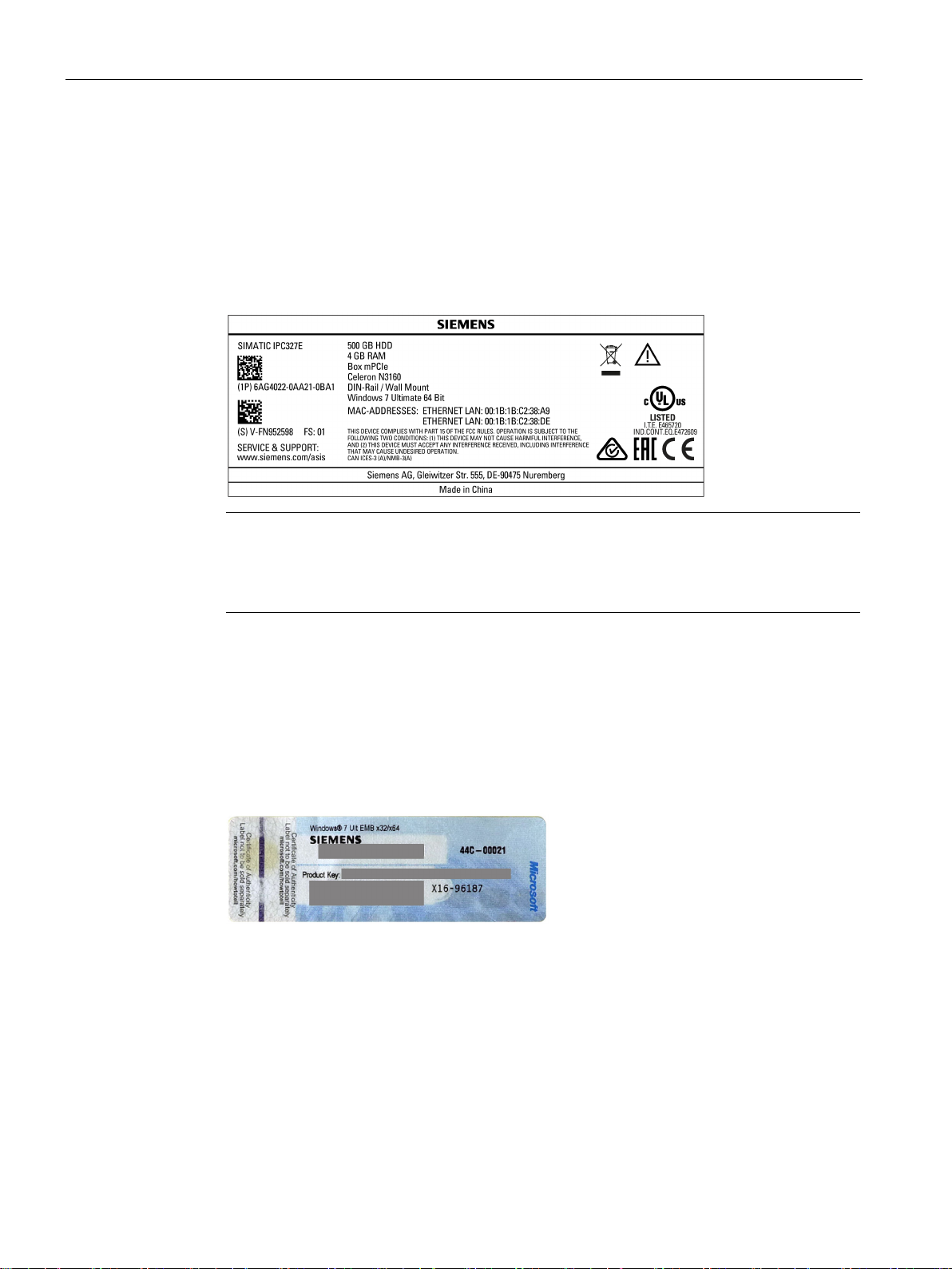
3.1.2
Identification data of the device
Order number
6AG...
Serial number
S V
Production version
FS
Windows "Product Key"
Ethernet address 1 (MAC)
Ethernet address 2 (MAC)
3.1 Preparing for installation
6. If the contents of the packaging are incomplete, damaged or do not match your order,
inform the responsible delivery service immediately.
A damaged device can be under hazardous voltage and trigger a fire in the machine or
plant. A damaged device has unpredictable properties and states.
Death or serious injury could occur.
Make sure that the damaged device is not inadvertently installed and put into operation.
Label the damaged device and keep it locked away. Send off the device for immediate
repair.
If the device is subjected to low temperatures or extreme fluctuations in temperature
during transportation, for example in cold weather, moisture could build up on or inside
the device.
Moisture causes a short circuit in electrical circuits and damages the device.
In order to prevent damage to the device, proceed as follows:
• Store the device in a dry place.
• Bring the device to room temperature before starting it up.
• Do not expose the device to direct heat radiation from a heating device.
• If condensation develops, wait approximately 12 hours or until the device is
completely dry before switching it on.
7. Please keep the enclosed documentation in a safe place. It belongs to the device. You
need the documentation when you commission the device for the first time.
8. Write down the identification data of the device.
The device can be clearly identified with the help of this identification data in case of repairs
or theft.
Enter the identification data in the following table:
SIMATIC IPC327E
Operating Instructions, 06/2019, A5E40965257-AD
17
Installing and connecting the device
Procedure
Note
Replacement device without storage media
When you order a replacement device, remove all the storage media from your device,
for example HDD. Insert the storage media into the replacement device.
Example of a COA label
3.1 Preparing for installation
Obtain the data from the product label and COA label. The product label is located on the
back panel of the device. The COA label is only available in pre-installed Windows operating
systems and is affixed to the rear of the device.
1. Get the information of order number, serial number, production version (FS), and
Ethernet addresses from the product label. Below is an example of a product label.
2. Take down the Windows "Product Key" from the COA label.
Microsoft Windows "Product Key" on the "Certificate Of Authenticity" (COA):
The COA label is only attached to the rear of the device containing a preinstalled and
activated Windows operating system.
● COA label of a device with Windows operating system
SIMATIC IPC327E
18 Operating Instructions, 06/2019, A5E40965257-AD

Installing and connecting the device
3.1.3
Permitted mounting positions
3.1 Preparing for installation
The following mounting positions are permitted:
● Horizontal mounting position
The horizontal mounting position is the preferred position.
● Vertical mounting position
SIMATIC IPC327E
Operating Instructions, 06/2019, A5E40965257-AD
19
Installing and connecting the device
3.2
Mounting the device
3.2.1
Mounting instructions
Note
If the equipment is used in manner not specified by the manufacture, the protection provided
by the equipment may be impaired.
3.2 Mounting the device
● Desk mounting position
Take into account the permitted temperature range for operation that depends on the
mounting position in accordance with the "Technical specifications (Page 51)" section.
Ensure that the following clearances measurements to another component or to a wall of a
housing are complied with:
● Below the device: ≥ 100 mm
● Above the device: ≥ 50 mm
Note the following:
● The device is approved for operation indoor only.
● For installation in a control cabinet, observe the applicable country-specific regulations.
● When the device is used in the area of Industrial Control Equipment in accordance with
UL61010-2-201, note that the device is classified as "Open Type". A UL61010-2-201
conform enclosure is therefore a requirement for approval or operation according to
UL61010-2-201.
● All the external circuit of the device should be SELV circuit.
SIMATIC IPC327E
20 Operating Instructions, 06/2019, A5E40965257-AD
Installing and connecting the device
Mounting on a
standard rail
Wall mounting
Position of the interfaces
Fasten securely
NOTICE
Insufficient load carrying capacity
3.2 Mounting the device
Possible mounting types of the device:
The mounting types are described in the following sections using the basic device as an
example.
For standard rail, the interface side of device can point either up or down. In the case of wall
mounting, the interface side of the device can point up, down, to the left or to the right.
If the mounting surface for wall and vertical mounting does not have sufficient load carrying
capability, the device may fall down and be damaged.
Ensure that the mounting surface on the wall can bear four times the total weight of the
device, including fixing elements.
SIMATIC IPC327E
Operating Instructions, 06/2019, A5E40965257-AD
21

Installing and connecting the device
NOTICE
Incorrect fixing elements
Material
Bore diameter
Fixing element
min. 13 mm thick
3.2.2
Mounting on a standard rail
Requirement
3.2 Mounting the device
If you use anchors and screws other than those specified below for wall and vertical
mounting, safe mounting is not guaranteed. The device can fall and may be damaged.
Use only the anchors and screws specified in the following table.
Concrete Select according to the
specification of the
mounting elements used
Plasterboard,
Metal,
min. 2 mm thick
• Anchor, ∅ 6 mm, 40 mm long
• Screw, ∅ 4-5 mm, 40 mm long
Toggle plug, ∅ 12 mm, 50 mm long
• Screw M4 × 15
• M4 nut
Mounting on a standard rail is suitable for horizontal mounting of the device.
● A SIEMENS 35 mm standard rail TH35-15 conforming to EN 60715:2001
The standard rail is mounted.
SIMATIC IPC327E
22 Operating Instructions, 06/2019, A5E40965257-AD
Installing and connecting the device
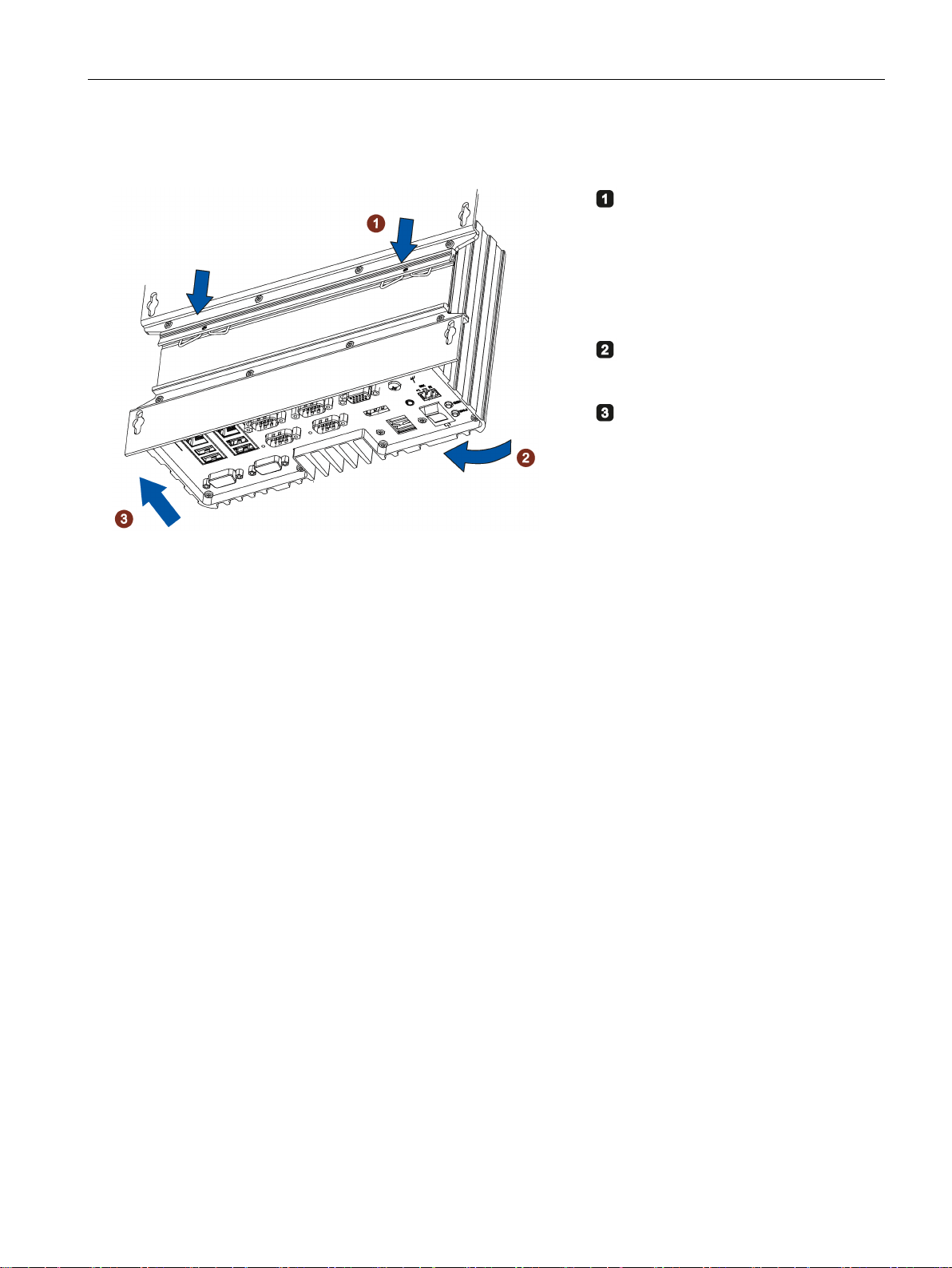
Procedure for mounting
Place the device with the standard
rail bracket onto the mounting rail
from above.
If the device is tilted when you place
it down, the standard rail bracket
does not grip.
Press the device down and toward
the standard rail until the standard
rail bracket engages.
Check whether the device is seated
firmly on the standard rail.
Procedure for dismantling
3.2 Mounting the device
1. Press the device down until the lower rail guide frees the device.
2. Swing the device out of the rails.
3. Remove the device from the rail.
SIMATIC IPC327E
Operating Instructions, 06/2019, A5E40965257-AD
23
Installing and connecting the device
3.2.3
Wall mounting
Requirement
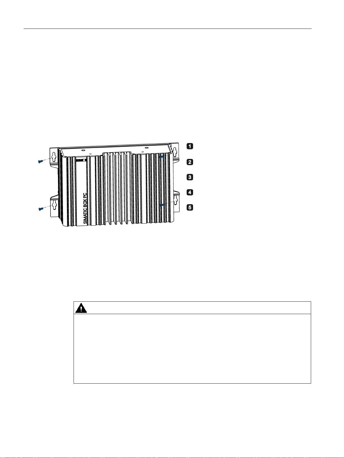
Procedure for mounting
3.3
Connecting the device
3.3.1
Notes on connecting
WARNING
Risk of fire and electric shock
The on/off switch does not isolate the device from the power supply. Risk of electric shock if
3.3 Connecting the device
Wall mounting is suitable for both horizontal and vertical mounting of the device.
● A screwdriver
● Four anchors and four screws
Place the device onto the mounting surface.
Mark the fixing holes.
Drill the fixing holes.
Insert the anchors in the drilled holes.
Screw on the device.
the device is opened incorrectly or defective. There is also a risk of fire if the device or
connecting lines are damaged. Death or serious bodily injury can result.
You should therefore protect the device as follows:
• Always pull out the power plug when you are not using the device or if the device is
defective. The power plug must be freely accessible.
• Use a central power isolating switch for cabinet installation.
SIMATIC IPC327E
24 Operating Instructions, 06/2019, A5E40965257-AD
Installing and connecting the device
WARNING
Risk of lightning strikes
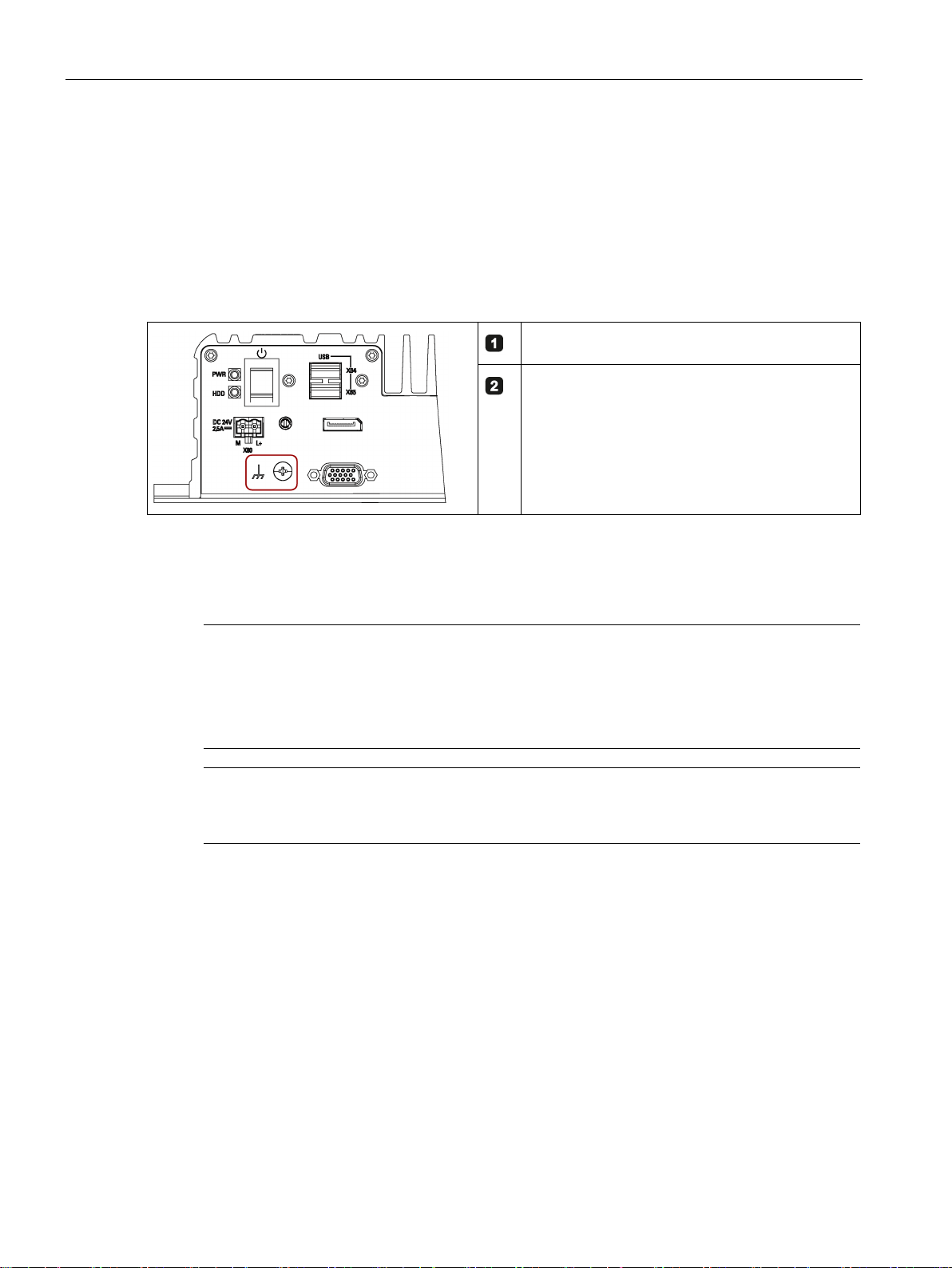
3.3.2
Connecting the function earth
Note
The function earth cannot connect hazard live parts.
WARNING
Electric shock and risk of fire
3.3 Connecting the device
A lightning flash may enter the mains cables and data transmission cables and jump to a
person.
Death, serious injury and burns can be caused by lightning.
Take the following precautions:
• Disconnect the device from the power supply in good time when a thunderstorm is
approaching.
• Do not touch mains cables and data transmission cables during a thunderstorm.
• Keep a sufficient distance from electric cables, distributors, systems, etc.
A connected function earth discharges dangerous electrical charges from the metal
enclosure. The current flowing through the function earth when such a fault occurs triggers
an upstream protective device that disconnects the machine from the power supply.
The function earth also improves the discharge of interference generated by external power
cables, signal cables or cables for I/O modules to ground.
The connection for the function earth is labeled with the following symbol:
High voltage may be present in a defective device, which can cause fire or an electric
shock if touched. Death and serious bodily injury can result.
• Connect the device to the function earth before you put it into operation.
• The function earth terminal on the device must be connected to the function earth of the
control cabinet or system in which the device is installed.
• Never operate the device without function earth.
• If a device is defective, remove it from operation without delay and label it accordingly.
SIMATIC IPC327E
Operating Instructions, 06/2019, A5E40965257-AD
25
Installing and connecting the device
Requirement
Procedure
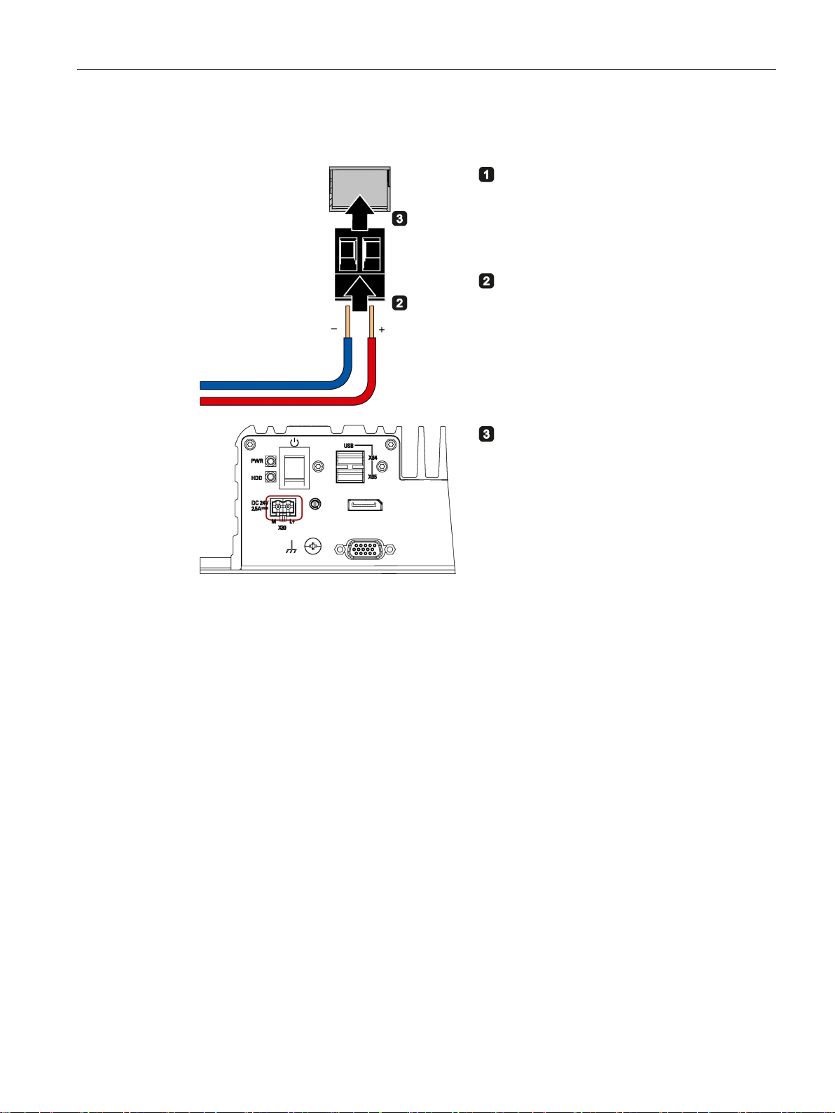
3.3.3
Connecting the power supply
Note
The device should only be connected to a 24 VDC power supply which satisfies t
requirements of safe extra low voltage (SELV) according to IEC/EN/DIN EN/UL 60950
The power supply must meet the requirement NEC Class 2 or LPS according to the
IEC/EN/DIN EN/UL 60950
Note
The 24 VDC power supply must be adapted to the input data of the device (see the technical
specifications in the operating instructions).
Requirement
3.3 Connecting the device
● PH2 screwdriver
● Cable lug for M4
● Function earth with minimum cross-section of 2.5 mm
2
copper cable
Clamp the cable lug on the function earth.
Firmly attach the cable lug to the function earth
connection on the device using the M4 thread (see
part labeled).
-1.
● The function earth is connected.
● You are using the supplied terminal.
● A two-core cable with a cable cross-section of 0.75 mm
connection.
● A slotted screwdriver with a 3mm blade.
he
2
to 2.5 mm2 for the 24 VDC
-1.
SIMATIC IPC327E
26 Operating Instructions, 06/2019, A5E40965257-AD
Installing and connecting the device
Procedure
Switch off the 24 VDC power supply.
Connect the cores of the power supply.
Insert the terminal at the indicated position.
3.3.4
Connect device to networks
Ethernet
3.3 Connecting the device
The following options are available for integrating the device in existing or planned system
environments and networks.
You can use the integrated Ethernet interfaces (10/100/1000 Mbps) for communication and
data exchange with automation devices, e.g. SIMATIC S7.
You need a suitable software to use this functionality: STEP 7, WinCC, SIMATIC NET.
SIMATIC IPC327E
Operating Instructions, 06/2019, A5E40965257-AD
27

Installing and connecting the device
Industrial Ethernet
Note
You need a category 6 Ethernet cable for operation at 1000 Mbps.
PROFINET
SIMATIC NET
Additional information
3.3 Connecting the device
You can establish a network between the device and other computers via Industrial Ethernet.
The on-board LAN interfaces are twisted-pair TP interfaces that support data transmission
rates of 10/100/1000 Mbps.
PROFINET RT can be operated via:
● Standard Ethernet interfaces
● Implemented PROFINET Driver and valid runtime license (for further information, refer to
PROFINET Driver (http://w3.siemens.com/mcms/distributed-io/en/profinet/profinet-
driver/pages/) )
Use this software package to create, operate and configure an innovative network for Field &
Control level. Information on this can be found on the SIMATIC NET Manual Collection CD.
The software package and the documentation are not included in the product package.
You can find additional information on the Internet at:
Technical support (https://support.industry.siemens.com/cs/?lc=en-WW)
SIMATIC IPC327E
28 Operating Instructions, 06/2019, A5E40965257-AD

4
4.1
General information on commissioning
Note
Windows Embedded Standard 7
Read the EWF and FBWF information
Two configurable write filters (Enhanced Write Filter and File Based Write Filter) are
provided wi
activate and use them, otherwise you may experience data loss.
Requirement
4.2
Initial commissioning
th Windows Embedded Standard. Read the EWF/FBWF information if you
● The device is connected to the power supply.
● The function earth is connected.
● The connection cables are plugged in correctly.
● The following hardware is available for initial commissioning:
– One USB keyboard
– One USB mouse
– A monitor/display
For the configuration with operating system pre-installed, the operating system is set up
automatically on the device after the initial switch on. The commissioning procedure in this
chapter is only applicable to the IPCs with operating system.
SIMATIC IPC327E
Operating Instructions, 06/2019, A5E40965257-AD
29

Commissioning the device and device functions
NOTICE
Faulty installation
Do not switch off the device during the entire installation process. Do not change the default
Note
If you install Windows 7 not by our restore or recovery DVD, you need to do the following two
steps:
•
•
If you install Windows 8 or Windows 10, you don't need to do the above two step
Procedure
Note
Once the operating system has been set up, the device may restart.
Result
4.2 Initial commissioning
For the configurations without operating system pre-installed, contact the operating system
provider to install the operating system firstly.
If you change the default values in the BIOS setup or if you turn off the device during the
installation, you disrupt the installation and the operating system is not installed correctly.
The operating safety of the device and the plant is at risk.
values in the BIOS setup.
Get the xHCI (USB) driver from the Documentation and Drivers DVD.
Refer to “Walkthrough: Create a Windows RE Image (https://technet.microsoft.com/en-
us/library/dd744525(v=ws.10).aspx)” to mount USB driver into the Windows Recovery
Environment(RE).
s.
1. Press the on/off switch.
The green POWER LED lights up. The module carries out a self-test.
2. Follow the instructions on the screen.
Press <ESC> or <DELETE> to enter setup.
3. Make the region and language settings.
If you want your system language to be international, select English. For information on
changing the region and language settings at a later point in time, refer to the section
Installing the software (Page 41).
The interface of the operating system is displayed every time you turn on the device and
after the startup routine.
SIMATIC IPC327E
30 Operating Instructions, 06/2019, A5E40965257-AD
 Loading...