

Siemens simatic ipc227e Operating Instructions Manual

___________________
___________________
___________________
___________________
___________________
___________________
___________________
___________________
___________________
___________________
___________________
SIMATIC
Industrial PC
SIMATIC IPC227E
Operating Instructions
11/2016
A5E357
Preface
Overview
1
Safety instructions
2
Installing and connecting the
device
3
Commissioning the device
and device functions
4
Expanding and assigning
parameters to the device
5
Maintaining and repairing the
device
6
Technical specifications
7
Technical support
A
Markings and symbols
B
List of abbreviations
C
82395-AB

Siemens AG
Division Digital Factory
Postfach 48 48
90026 NÜRNBERG
GERMANY
A5E35782395-AA
Ⓟ
Copyright © Siemens AG 2016.
All rights reserved
Legal information
Warning notice system
DANGER
indicates that death or severe personal injury will result if proper precautions are not taken.
WARNING
indicates that death or severe personal injury may result if proper precautions are not taken.
CAUTION
indicates that minor personal injury can result if proper precautions are not taken.
NOTICE
indicates that property damage can result if proper precautions are not taken.
Qualified Personnel
personnel qualified
Proper use of Siemens products
WARNING
Siemens products may only be used for the applications described in the catalog and in the relevant technical
ambient conditions must be complied with. The information in the relevant documentation must be observed.
Trademarks
Disclaimer of Liability
This manual contains notices you have to observe in order to ensure your personal safety, as well as to prevent
damage to property. The notices referring to your personal safety are highlighted in the manual by a safety alert
symbol, notices referring only to property damage have no safety alert symbol. These notices shown below are
graded according to the degree of danger.
If more than one degree of danger is present, the warning notice representing the highest degree of danger will
be used. A notice warning of injury to persons with a safety alert symbol may also include a warning relating to
property damage.
The product/system described in this documentation may be operated only by
task in accordance with the relevant documentation, in particular its warning notices and safety instructions.
Qualified personnel are those who, based on their training and experience, are capable of identifying risks and
avoiding potential hazards when working with these products/systems.
Note the following:
for the specific
documentation. If products and components from other manufacturers are used, these must be recommended
or approved by Siemens. Proper transport, storage, installation, assembly, commissioning, operation and
maintenance are required to ensure that the products operate safely and without any problems. The permissible
All names identified by ® are registered trademarks of Siemens AG. The remaining trademarks in this publication
may be trademarks whose use by third parties for their own purposes could violate the rights of the owner.
We have reviewed the contents of this publication to ensure consistency with the hardware and software
described. Since variance cannot be precluded entirely, we cannot guarantee full consistency. However, the
information in this publication is reviewed regularly and any necessary corrections are included in subsequent
editions.
12/2016 Subject to change

Preface
Basic knowledge requirements
Scope of validity of this document
Scope of this documentation
Conventions
History
Edition
Comment
11/2016
Amendment regarding Windows 10
These operating instructions contain all the information you need for commissioning and
operation of the SIMATIC IPC227E.
It is intended both for programming and testing personnel who commission the device and
connect it with other units (automation systems, programming devices), as well as for service
and maintenance personnel who install add-ons or carry out fault/error analyses.
A solid background in personal computers and Microsoft operating systems is required to
understand this manual. General knowledge in the field automation control engineering is
recommended.
These operating instructions are valid for all versions of the SIMATIC IPC227E.
The documentation for the SIMATIC IPC227E consists of:
● Product information, e.g. "Important notes on your device"
● Quick Install Guide SIMATIC IPC227E
● SIMATIC IPC227E operating instructions in English and German
The documentation is supplied with the IPC in multiple languages as PDF on the USB stick
supplied in the documentation package.
The terms "PC" and "device" are sometimes used to refer to the SIMATIC IPC227E in this
documentation.
In these operating instructions, "Windows Embedded Standard" is also used as a standard
term for "Windows Embedded Standard 7". The abbreviation "Windows 7" denotes the term
"Windows 7 Ultimate".
The following editions of these operating instructions have been published:
SIMATIC IPC227E
Operating Instructions, 11/2016, A5E35782395-AB
06/2015 First edition
3

Preface
SIMATIC IPC227E
4 Operating Instructions, 11/2016, A5E35782395-AB

Table of contents
Preface ...................................................................................................................................................... 3
1 Overview .................................................................................................................................................... 9
2 Safety instructions ................................................................................................................................... 19
3 Installing and connecting the device ........................................................................................................ 25
1.1 Product description ................................................................................................................... 9
1.2 Structure of the devices .......................................................................................................... 11
1.2.1 Views of the basic device ....................................................................................................... 11
1.2.2 Views of the PCIe device version ........................................................................................... 12
1.2.3 Interfaces and operator controls of the basic device .............................................................. 14
1.2.4 Interfaces and operator controls PCIe device version ............................................................ 15
1.2.5 Status displays ........................................................................................................................ 16
1.3 Accessories ............................................................................................................................. 17
2.1 General safety instructions ..................................................................................................... 19
2.2 Notes on use ........................................................................................................................... 23
3.1 Preparing for installation ......................................................................................................... 25
3.1.1 Checking the delivery package ............................................................................................... 25
3.1.2 Identification data of the device .............................................................................................. 27
3.1.3 Permitted mounting positions ................................................................................................. 29
3.1.4 Installing the cable strain relief ............................................................................................... 30
3.1.5 Installing Ethernet connector strain relief ............................................................................... 31
3.1.6 Installing the ATEX cable strain relief ..................................................................................... 32
3.2 Mounting the device ................................................................................................................ 32
3.2.1 Mounting instructions .............................................................................................................. 32
3.2.2 Mounting on a standard rail .................................................................................................... 35
3.2.3 Wall mounting ......................................................................................................................... 36
3.2.4 Upright mounting ..................................................................................................................... 37
3.3 Connecting the device ............................................................................................................ 38
3.3.1 Notes on connecting ............................................................................................................... 38
3.3.2 Connecting the protective conductor ...................................................................................... 40
3.3.3 Connecting the power supply ................................................................................................. 41
3.3.4 Connect device to networks .................................................................................................... 43
SIMATIC IPC227E
Operating Instructions, 11/2016, A5E35782395-AB
5

Table of contents
4 Commissioning the device and device functions ...................................................................................... 45
5 Expanding and assigning parameters to the device ................................................................................. 55
6 Maintaining and repairing the device ....................................................................................................... 63
4.1 General information on commissioning ................................................................................. 45
4.2 Switching on the device ......................................................................................................... 46
4.3 Windows Security Center ....................................................................................................... 47
4.4 Advanced device functions .................................................................................................... 48
4.4.1 Monitoring functions ............................................................................................................... 48
4.4.1.1 Overview of the monitoring functions ..................................................................................... 48
4.4.1.2 Temperature monitoring/display ............................................................................................ 49
4.4.1.3 Watchdog (WD) ...................................................................................................................... 49
4.4.1.4 Battery monitoring .................................................................................................................. 50
4.4.2 Enhanced Write Filter ............................................................................................................ 51
4.4.3 File-Based Write Filter ........................................................................................................... 53
4.4.4 Buffer memory NVRAM ......................................................................................................... 54
5.1 Open the device ..................................................................................................................... 55
5.2 Installing a PCIe module ........................................................................................................ 57
5.3 Installing and removing CFast cards...................................................................................... 60
6.1 Maintenance ........................................................................................................................... 63
6.2 Repair information .................................................................................................................. 63
6.3 Installing and removing hardware .......................................................................................... 65
6.3.1 Replace the backup battery ................................................................................................... 65
6.3.2 Replacing the drive of a basic device .................................................................................... 68
6.3.3 Replacing a drive for the PCIe device version ....................................................................... 70
6.4 Installing the software ............................................................................................................ 72
6.4.1 Reinstalling the operating system .......................................................................................... 72
6.4.1.1 General installation procedure ............................................................................................... 72
6.4.1.2 Restoring the delivery state ................................................................................................... 73
6.4.1.3 Installation of Windows 7 ....................................................................................................... 75
6.4.1.4 Windows with AHCI Controller ............................................................................................... 77
6.4.1.5 Setting up the language selection by means of the Multilanguage User Interface (MUI) ...... 80
6.4.2 Partitioning data media .......................................................................................................... 82
6.4.3 Installing drivers and software ............................................................................................... 82
6.4.4 Installing updates ................................................................................................................... 83
6.4.4.1 Updating the operating system .............................................................................................. 83
6.4.4.2 Installing or updating application programs and drivers ........................................................ 83
6.4.5 Backing up data ..................................................................................................................... 83
6.5 Recycling and disposal .......................................................................................................... 84
SIMATIC IPC227E
6 Operating Instructions, 11/2016, A5E35782395-AB

Table of contents
7 Technical specifications ........................................................................................................................... 85
7.1 Certificates and approvals ...................................................................................................... 85
7.1.1 FCC (USA) and ICES (Canada) Compliance ......................................................................... 87
7.2 Directives and declarations ..................................................................................................... 89
7.2.1 Electromagnetic compatibility, Industrial and Residential Areas ............................................ 89
7.2.2 ESD guideline ......................................................................................................................... 90
7.3 Dimension drawings................................................................................................................ 93
7.3.1 Dimension drawing basic device ............................................................................................ 93
7.3.2 Dimension drawing PCIe device version ................................................................................ 96
7.4 Technical data ......................................................................................................................... 99
7.4.1 General technical specifications ............................................................................................. 99
7.4.2 Ambient conditions ................................................................................................................ 102
7.4.3 Shipbuilding .......................................................................................................................... 104
7.4.4 Power demand of the components ....................................................................................... 104
7.4.5 Direct current supply (DC) .................................................................................................... 105
7.5 Hardware descriptions .......................................................................................................... 106
7.5.1 Technical features of the motherboard ................................................................................. 106
7.5.2 External interfaces ................................................................................................................ 106
7.5.2.1 Overview of interfaces .......................................................................................................... 106
7.5.2.2 Serial interface ...................................................................................................................... 107
7.5.2.3 CFast .................................................................................................................................... 109
7.5.2.4 USB 2.0 port ......................................................................................................................... 110
7.5.2.5 USB 3.0 port ......................................................................................................................... 110
7.5.2.6 DisplayPort ............................................................................................................................ 111
7.5.2.7 Ethernet port ......................................................................................................................... 112
7.5.3 Internal interfaces ................................................................................................................. 113
7.5.3.1 Overview of internal interfaces ............................................................................................. 113
7.5.3.2 PCIe interface ....................................................................................................................... 113
7.5.4 System resources ................................................................................................................. 114
7.5.4.1 Currently allocated system resources ................................................................................... 114
7.5.4.2 System resources occupied by the BIOS/DOS .................................................................... 114
7.5.5 Input/output address areas ................................................................................................... 116
7.5.5.1 Overview of the internal module registers ............................................................................ 116
7.5.5.2 Watchdog enable register / 066h select register (read/write, address 062h) ....................... 116
7.5.5.3 Watchdog trigger register (read only, address 066h) ........................................................... 117
7.5.5.4 Output register user LED L1/L2/L3 (read/write, address 404Eh) ......................................... 117
7.5.5.5 Battery status register (read-only, address 50Ch) ................................................................ 118
7.5.5.6 NVRAM address register ...................................................................................................... 118
7.6 BIOS description ................................................................................................................... 11
7
.6.1 Overview ............................................................................................................................... 119
7.6.2 Opening the BIOS selection menu ....................................................................................... 120
7.6.3 Structure of the BIOS Setup menu ....................................................................................... 122
7.6.4 Exit menu .............................................................................................................................. 124
7.6.5 Default BIOS Setup entries ................................................................................................... 125
7.6.6 BIOS update ......................................................................................................................... 128
7.6.7 Alarm, error and system messages ...................................................................................... 129
7.7 Functional scope in Windows ............................................................................................... 130
7.7.1 Windows Embedded Standard 7 .......................................................................................... 130
SIMATIC IPC227E
Operating Instructions, 11/2016, A5E35782395-AB
9
7

Table of contents
A Technical support .................................................................................................................................. 133
B Markings and symbols ........................................................................................................................... 137
C List of abbreviations ............................................................................................................................... 141
Glossary ................................................................................................................................................ 145
Index ...................................................................................................................................................... 153
A.1 Service and support ............................................................................................................. 133
A.2 Troubleshooting ................................................................................................................... 134
A.3 Notes on the use of third-party modules .............................................................................. 135
B.1 Overview .............................................................................................................................. 137
B.2 Safety ................................................................................................................................... 137
B.3 Operator controls ................................................................................................................. 137
B.4 Certificates, approvals and markings ................................................................................... 138
B.5 Interfaces ............................................................................................................................. 139
SIMATIC IPC227E
8 Operating Instructions, 11/2016, A5E35782395-AB
1
1.1
Product description
SIMATIC IPC227E
Operating Instructions, 11/2016, A5E35782395-AB
9

Overview
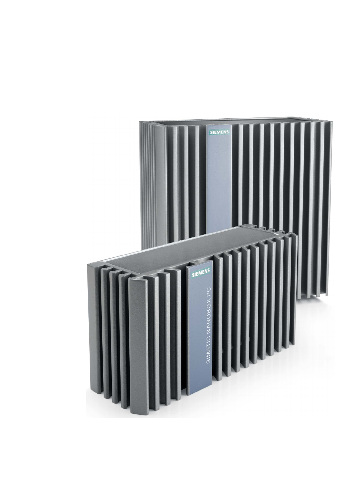
1.1 Product description
SIMATIC IPC227E provides high-level industrial functionality.
● Compact design
● High degree of ruggedness
● Maintenance-free operation possible
SIMATIC IPC227E
10 Operating Instructions, 11/2016, A5E35782395-AB
Overview
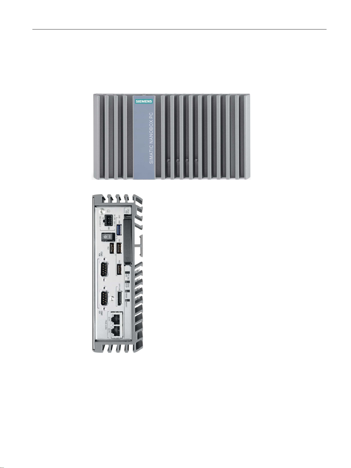
1.2
Structure of the devices
1.2.1
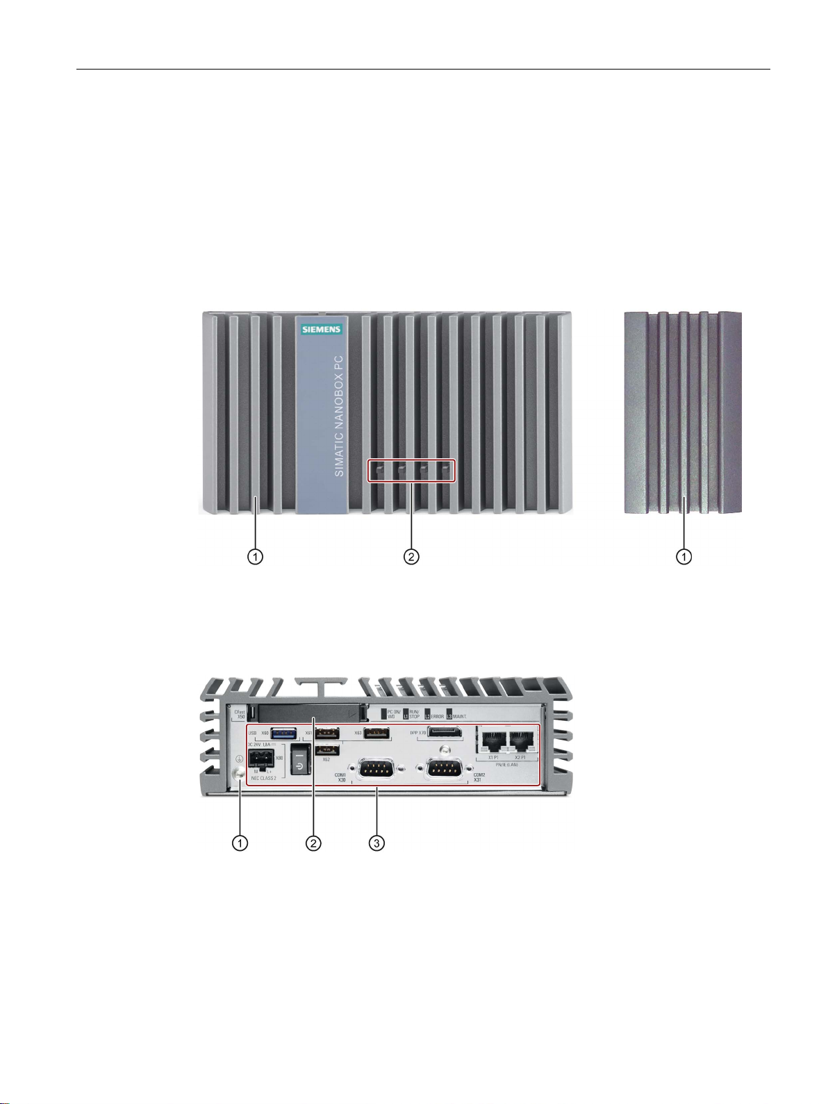
Views of the basic device
Front view and side view
①
Cooling fins
②
LED display
Bottom view
①
Protective conductor connection
②
Memory card slot
③
Ports
1.2 Structure of the devices
The front view on the left is the standard mounting position, side view on the right.
SIMATIC IPC227E
Operating Instructions, 11/2016, A5E35782395-AB
11
Overview
1.2.2
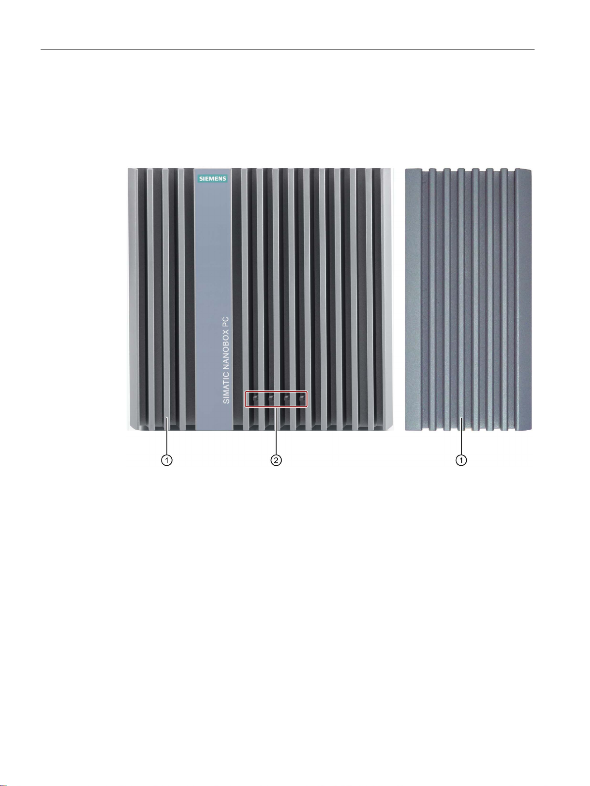
Views of the PCIe device version
Front view and side view
①
Cooling fins
②
LED display
1.2 Structure of the devices
The front view on the left is the standard mounting position, side view on the right.
SIMATIC IPC227E
12 Operating Instructions, 11/2016, A5E35782395-AB
Overview
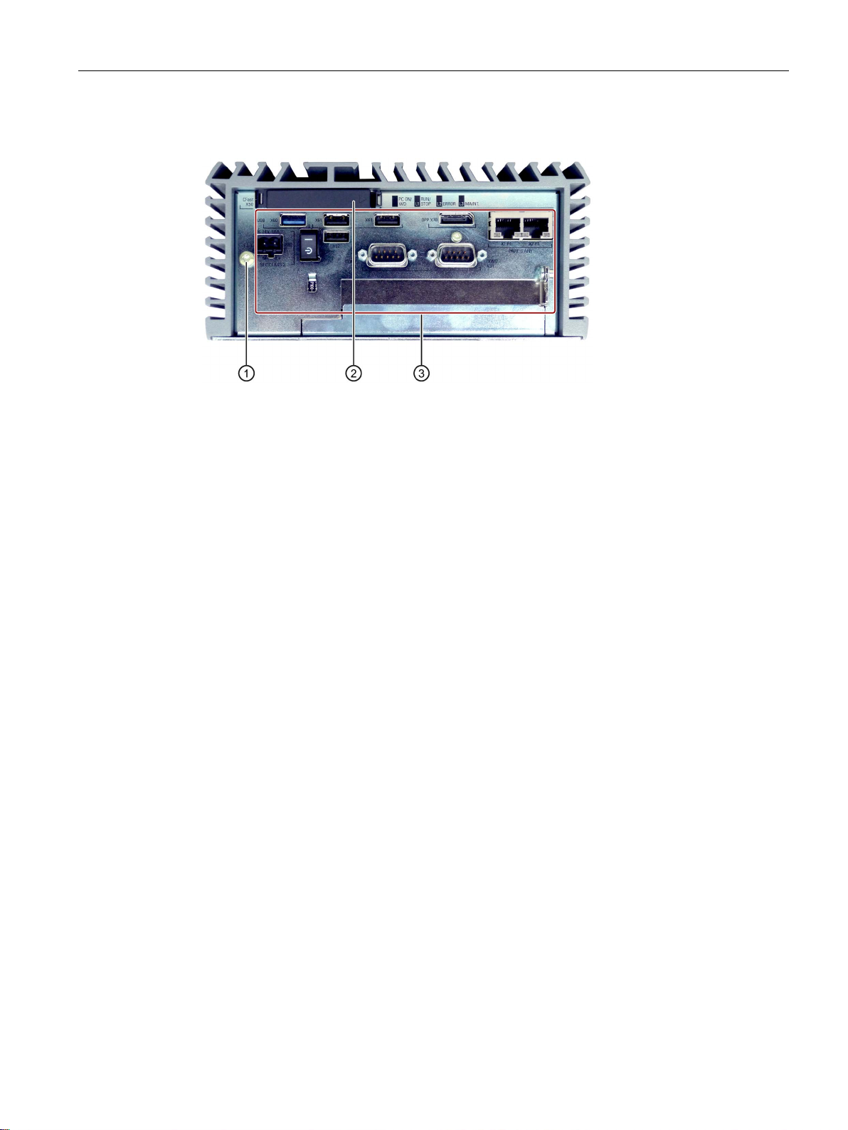
Bottom view
①
Protective conductor connection
②
Memory card slot
③
Ports
1.2 Structure of the devices
SIMATIC IPC227E
Operating Instructions, 11/2016, A5E35782395-AB
13
Overview
1.2.3
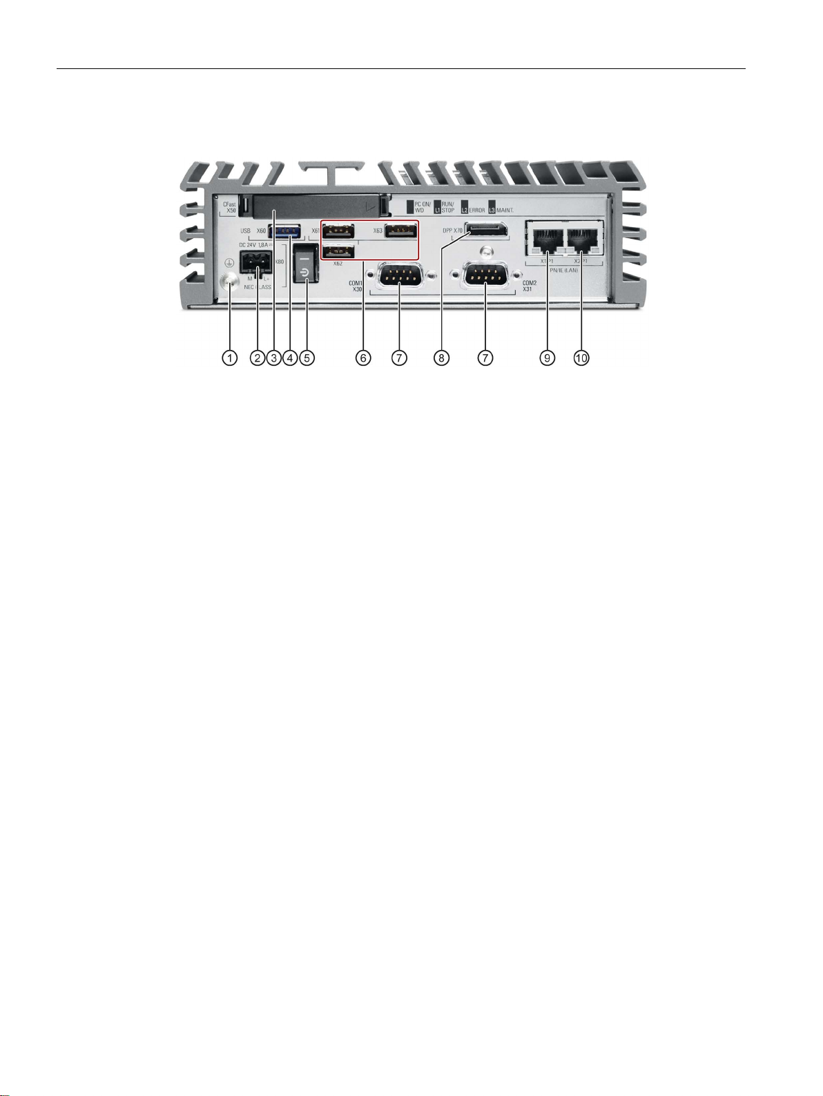
Interfaces and operator controls of the basic device
①
Protective conductor connection
②
Connection for a 24 VDC power supply
③
Memory card slot
④
USB 3.0 port, high current
⑤
On/off switch. OFF position, when the symbol "C
⑥
USB 2.0 port, high current
⑦
Serial interface, 9
•
•
•
⑧
DisplayPort connection
⑨
RJ45 Ethernet connection 1 for 10/100/1000 Mbps
⑩
RJ45 Ethernet connection 2 for 10/100/1000
1.2 Structure of the devices
-" is pressed in.
-pin (optional)
RS 232
RS 422
RS-485
Mbps
SIMATIC IPC227E
14 Operating Instructions, 11/2016, A5E35782395-AB
Overview
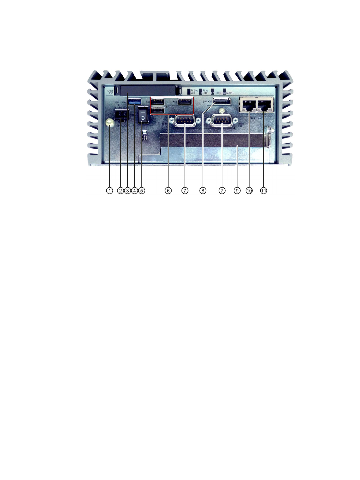
1.2.4
Interfaces and operator controls PCIe device version
①
Protective conductor
②
Connection for a 24 VDC power supply
③
Memory card slot
④
USB 3.0 port, high current
⑤
On/off switch. OFF position, when the symbol "C
⑥
USB 2.0 port, high current
⑦
Serial interface, 9
•
•
•
⑧
DisplayPort connection
⑨
Slot for a PCIe x1 card
⑩
RJ45 Ethernet connection 1 for 10/100/1000 Mbps
⑪
RJ45 Ethernet connection 2 for 10/100/1000
1.2 Structure of the devices
connection
-" is pressed in.
-pin
RS 232
RS 422
RS-485
Mbps
SIMATIC IPC227E
Operating Instructions, 11/2016, A5E35782395-AB
15
Overview
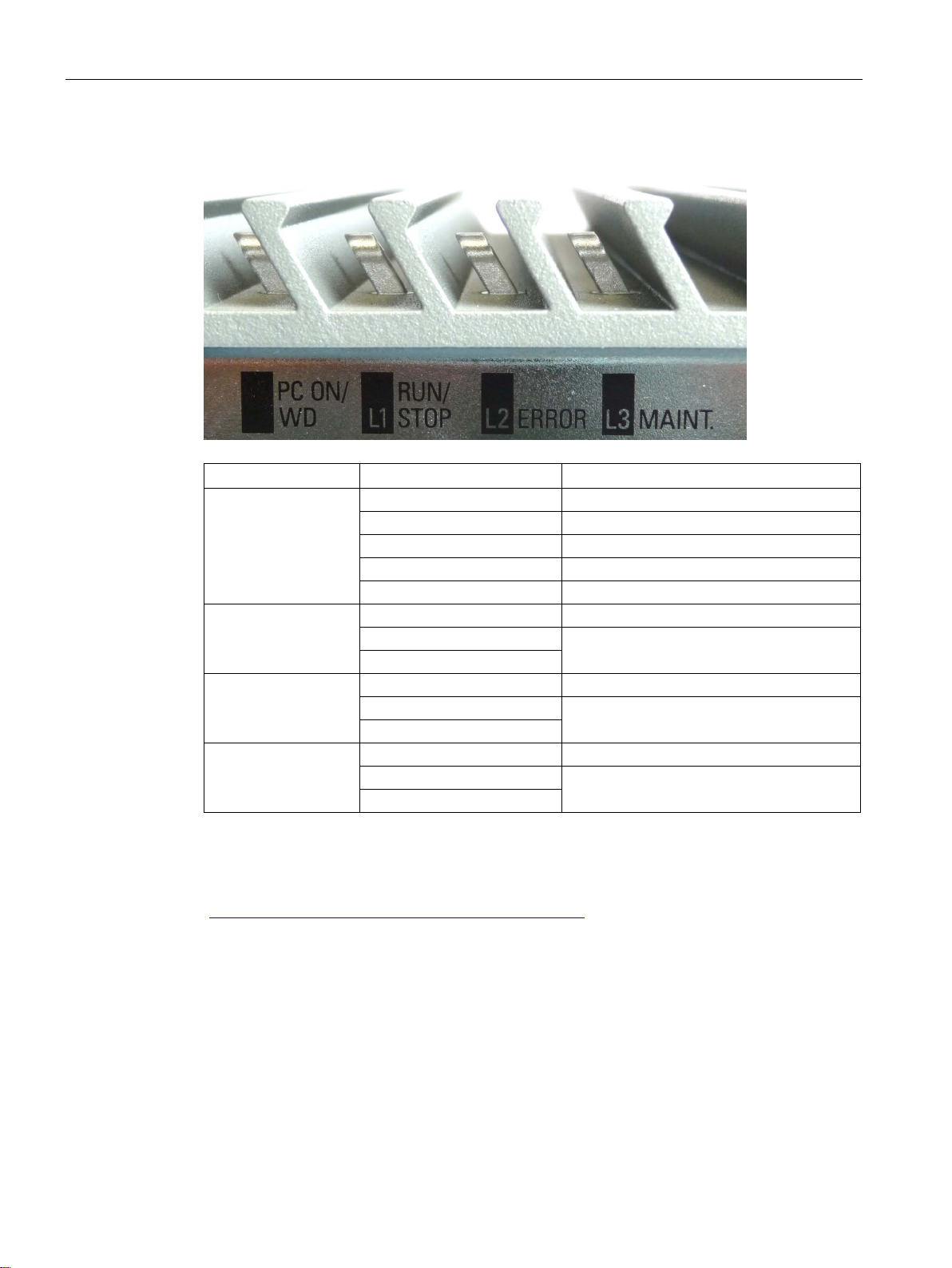
1.2.5
Status displays
LED
State
Description
Off - Green
BIOS ready to boot
Flashing green/yellow (1 Hz)
BIOS in POST, power switch on
Yellow
Idle state
Flashing red (1 Hz)
Watchdog status display: active
Off - Green
Yellow
Off - Red
Yellow
Off - Yellow
Red
1.2 Structure of the devices
PC ON/WD
RUN/STOP / L1
Can be controlled by user program / control
program (e.g. WinAC)
ERROR / L2
Can be controlled by user program / control
program (e.g. WinAC)
MAINT /
L3
Can be controlled by user program / control
program (e.g. WinAC)
You can find information on the individual LEDs in the section Output register user
LED L1/L2/L3 (read/write, address 404Eh) (Page 117). Example programs for controlling the
LEDs on Windows operating systems are available on the Customer Support page of
Siemens Industry Automation and Drive Technologies.
(http://www.siemens.com/automation/service&support)
SIMATIC IPC227E
16 Operating Instructions, 11/2016, A5E35782395-AB
Overview
1.3
Accessories
CFast cards
Note
CFast cards can only be replaced with cards of the same manufacturing versions
This device supports only SIMATIC IPC CFast cards with version
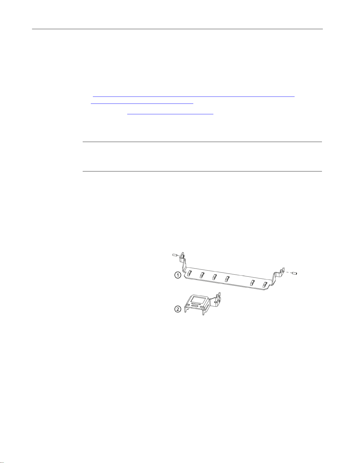
Strain relief
The cable strain relief set co
tains:
•
•
•
•
•
Dust protection set
1.3 Accessories
This chapter contains the scope of accessories valid at the time these operating instructions
were written. Additional accessories can be found on the Internet at:
● Expansion components and accessories
(http://www.automation.siemens.com/mcms/pc-based-automation/en/industrial-
pc/expansion_components_accessories)
● Industry Mall (https://mall.industry.siemens.com)
02 or higher.
The following CFast cards can be ordered:
● CFast card, 4 GB
● CFast card, 8 GB
● CFast card, 16 GB
The Dust protection set interfaces contains:
● 40 pieces covers for USB interface
n-
5 pieces cable strain relief ①
5 pieces Ethernet connector
strain relief
Setscrews M3x8
Allen key
Cable ties
②
● 20 pieces covers for RJ45 Ethernet connection
● 20 pieces DisplayPort cover
SIMATIC IPC227E
Operating Instructions, 11/2016, A5E35782395-AB
17

Overview
Graphics adapter
1.3 Accessories
● DisplayPort DVI adapter
● DisplayPort VGA adapter
SIMATIC IPC227E
18 Operating Instructions, 11/2016, A5E35782395-AB

2
2.1
General safety instructions
WARNING
Life-threatening voltages are present with an open control cabinet
System expansions
NOTICE
Damage through system expansions
WARNING
Risk of fire through expansion cards
nclosure that is compliant with sections 4.6 and 4.7.3
When you install the device in a control cabinet, some areas or components in the open
control cabinet may be carrying life-threatening voltages.
If you touch these areas or components, you may be killed by electric shock.
Switch off the power supply to the cabinet before opening it.
Device and system expansions may be faulty and can affect the entire machine or plant.
The installation of expansions can damage the device, machine or plant. Device and
system expansions may violate safety rules and regulations regarding radio interference
suppression. If you install or exchange system expansions and damage your device, the
warranty becomes void.
Note the following for system expansions:
● Only install system expansion devices designed for this device. Contact your technical
● Observe the information on electromagnetic compatibility (Page 89).
Expansion cards generate additional heat. The device may overheat and cause a fire.
support team or where you purchased your PC to find out which system expansion
devices may safely be installed.
Please note the following:
• Observe the safety and installation instructions for the expansion cards.
• If in doubt, install the device in an e
of the IEC/UL/EN/DIN-EN 60950-1 standard.
SIMATIC IPC227E
Operating Instructions, 11/2016, A5E35782395-AB
19

Safety instructions
NOTICE
"Open Type" UL508
Battery and rechargeable battery
WARNING
Risk of explosion and release of harmful substances
Strong high-frequency radiation
NOTICE
Observe immunity to RF radiation
2.1 General safety instructions
Note that the device is classified as "Open Type" for use in the area of Industrial Control
Equipment (UL508). A UL508 conform enclosure is therefore a mandatory requirement for
approval or operation according to UL508.
Improper handling of lithium batteries can result in an explosion of the batteries.
Explosion of the batteries and the released pollutants can cause severe physical injury.
Worn batteries jeopardize the function of the device.
Note the following when handling lithium batteries:
• Replace used batteries in good time; see the section "Replacing the backup battery" in
the operating instructions.
• Replace the lithium battery only with an identical battery or types recommended by the
manufacturer (order no.: A5E34345932).
• Do not throw lithium batteries into fire, do not solder on the cell body, do not recharge,
do not open, do not short-circuit, do not reverse polarity, do not heat above 100°C and
protect from direct sunlight, moisture and condensation.
The device has an increased immunity to RF radiation according to the specifications on
electromagnetic compatibility in the technical specifications.
Radiation exposure in excess of the specified immunity limits can impair device functions,
result in malfunctions and therefore injuries or damages.
Read the information on immunity to RF radiation in the technical specifications.
SIMATIC IPC227E
20 Operating Instructions, 11/2016, A5E35782395-AB

Safety instructions
ESD Guideline
NOTICE
Electrostatic sensitive devices (ESD)
When you touch electrostatic sensitive components, you can destroy them through voltages
Industrial Security
2.1 General safety instructions
Electrostatic sensitive devices can be labeled with an appropriate symbol.
that are far below the human perception threshold.
If you work with components that can be destroyed by electrostatic discharge, observe the
ESD Guideline (Page 90).
Siemens provides products and solutions with industrial security functions that support the
secure operation of plants, systems, machines and networks.
In order to protect plants, systems, machines and networks against cyber threats, it is
necessary to implement – and continuously maintain – a holistic, state-of-the-art industrial
security concept. Siemens’ products and solutions only form one element of such a concept.
Customer is responsible to prevent unauthorized access to its plants, systems, machines
and networks. Systems, machines and components should only be connected to the
enterprise network or the internet if and to the extent necessary and with appropriate security
measures (e.g. use of firewalls and network segmentation) in place.
Additionally, Siemens’ guidance on appropriate security measures should be taken into
account. For more information about industrial security, please visit
(http://www.siemens.com/industrialsecurity).
Siemens’ products and solutions undergo continuous development to make them more
secure. Siemens strongly recommends to apply product updates as soon as available and to
always use the latest product versions. Use of product versions that are no longer supported,
and failure to apply latest updates may increase customer’s exposure to cyber threats.
To stay informed about product updates, subscribe to the Siemens Industrial Security RSS
Feed under (https://support.industry.siemens.com).
SIMATIC IPC227E
Operating Instructions, 11/2016, A5E35782395-AB
21

Safety instructions
Disclaimer for third-party software updates
Notes on protecting administrator accounts
2.1 General safety instructions
This product includes third-party software. Siemens AG only provides a warranty for
updates/patches of the third-party software, if these have been distributed as part of a
Siemens software update service contract or officially released by Siemens AG. Otherwise,
updates/patches are undertaken at your own risk. You can find more information about our
Software Update Service offer on the Internet at Software Update Service
(http://www.automation.siemens.com/mcms/automation-software/en/software-update-
service).
A user with administrator privileges has extensive access and manipulation options in the
system.
Therefore, ensure there are adequate safeguards for protecting the administrator accounts
to prevent unauthorized changes. To do this, use secure passwords and a standard user
account for normal operation. Other measures, such as the use of security policies, should
be applied as needed.
SIMATIC IPC227E
22 Operating Instructions, 11/2016, A5E35782395-AB

Safety instructions
2.2
Notes on use
NOTICE
Possible functional restrictions in case of non-validated plant operation
Note
Use in an industrial environment without additional protective measures
This device was designed for use in a normal industrial environment according to
IEC
2.2 Notes on use
The device is tested and certified on the basis of the technical standards. In rare cases,
functional restrictions can occur during plant operation.
Validate the correct functioning of the plant to avoid functional restrictions.
60721-3-3.
SIMATIC IPC227E
Operating Instructions, 11/2016, A5E35782395-AB
23

Safety instructions
2.2 Notes on use
SIMATIC IPC227E
24 Operating Instructions, 11/2016, A5E35782395-AB

3
3.1
Preparing for installation
3.1.1
Checking the delivery package
Procedure
Note
Damage to the device during transport and storage
If a device is transported or stored without packaging, shocks, vibrations, pressure and
moisture may impact the unprotected unit. A damaged packaging indicates that ambient
conditions have already had a massive impact on the device.
The device may be damaged.
Do not dispose of the original packaging. Pack the device during transportation and
storage.
1. When accepting a delivery, please check the packaging for visible transport damage.
2. If any transport damage is present at the time of delivery, lodge a complaint at the
shipping company in charge. Have the shipper confirm the transport damage
immediately.
3. Unpack the device at its installation location.
4. Keep the original packaging in case you have to transport the unit again.
5. Check the contents of the packaging and any accessories you may have ordered for
completeness and damage.
SIMATIC IPC227E
Operating Instructions, 11/2016, A5E35782395-AB
25

Installing and connecting the device
WARNING
Electric shock and fire hazard due to damaged device
NOTICE
Damage from condensation
3.1 Preparing for installation
6. If the contents of the packaging are incomplete, damaged or do not match your order,
inform the responsible delivery service immediately. Fax the enclosed form "SIMATIC
IPC/PG Quality Control Report".
A damaged device can be under hazardous voltage and trigger a fire in the machine or
plant. A damaged device has unpredictable properties and states.
Death or serious injury could occur.
Make sure that the damaged device is not inadvertently installed and put into operation.
Label the damaged device and keep it locked away. Send off the device for immediate
repair.
If the device is subjected to low temperatures or extreme fluctuations in temperature
during transportation, for example in cold weather, moisture could build up on or inside
the HMI device.
Moisture causes a short circuit in electrical circuits and damages the device.
In order to prevent damage to the device, proceed as follows:
• Store the device in a dry place.
• Bring the device to room temperature before starting it up.
• Do not expose the device to direct heat radiation from a heating device.
• If condensation develops, wait approximately 12 hours or until the device is
completely dry before switching it on.
7. Please keep the enclosed documentation in a safe place. It belongs to the device. You
need the documentation when you commission the device for the first time.
8. Write down the identification data of the device.
SIMATIC IPC227E
26 Operating Instructions, 11/2016, A5E35782395-AB
Installing and connecting the device
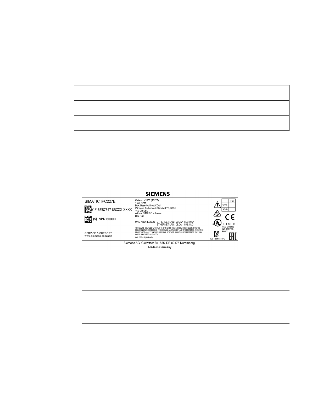
3.1.2
Identification data of the device
Serial number
S VP
Windows "Product Key"
Ethernet address 1 (MAC)
Ethernet address 2 (MAC)
Procedure
Note
Replacement device without storage media
When you order a replacement device, remove all the storage media from your device,
for example SSD. Insert the storage media into the replacement device.
3.1 Preparing for installation
The device can be clearly identified with the help of this identification data in case of repairs
or theft.
Enter the identification data in the following table:
Order number 6ES ...
Production version FS
Obtain the data from the rating plate and COA label. The rating plate is located on the back
panel of the device. The COA label is only available in pre-installed Windows operating
systems and is affixed to the rear of the device.
1. Transfer order number, serial number, production version (FS), and Ethernet addresses
from the rating plate.
The Ethernet addresses can also be found in the BIOS Setup under "Main > Advanced >
Peripheral Configuration" (see section "Technical Specifications").
Replacement device: On the rating plate, the order number of a replacement device
which is available from stock at short notice is listed under "Spare Part Space Units". The
replacement device is always supplied without storage media.
2. Transfer the Windows "Product Key" from the COA label.
SIMATIC IPC227E
Operating Instructions, 11/2016, A5E35782395-AB
27
Installing and connecting the device
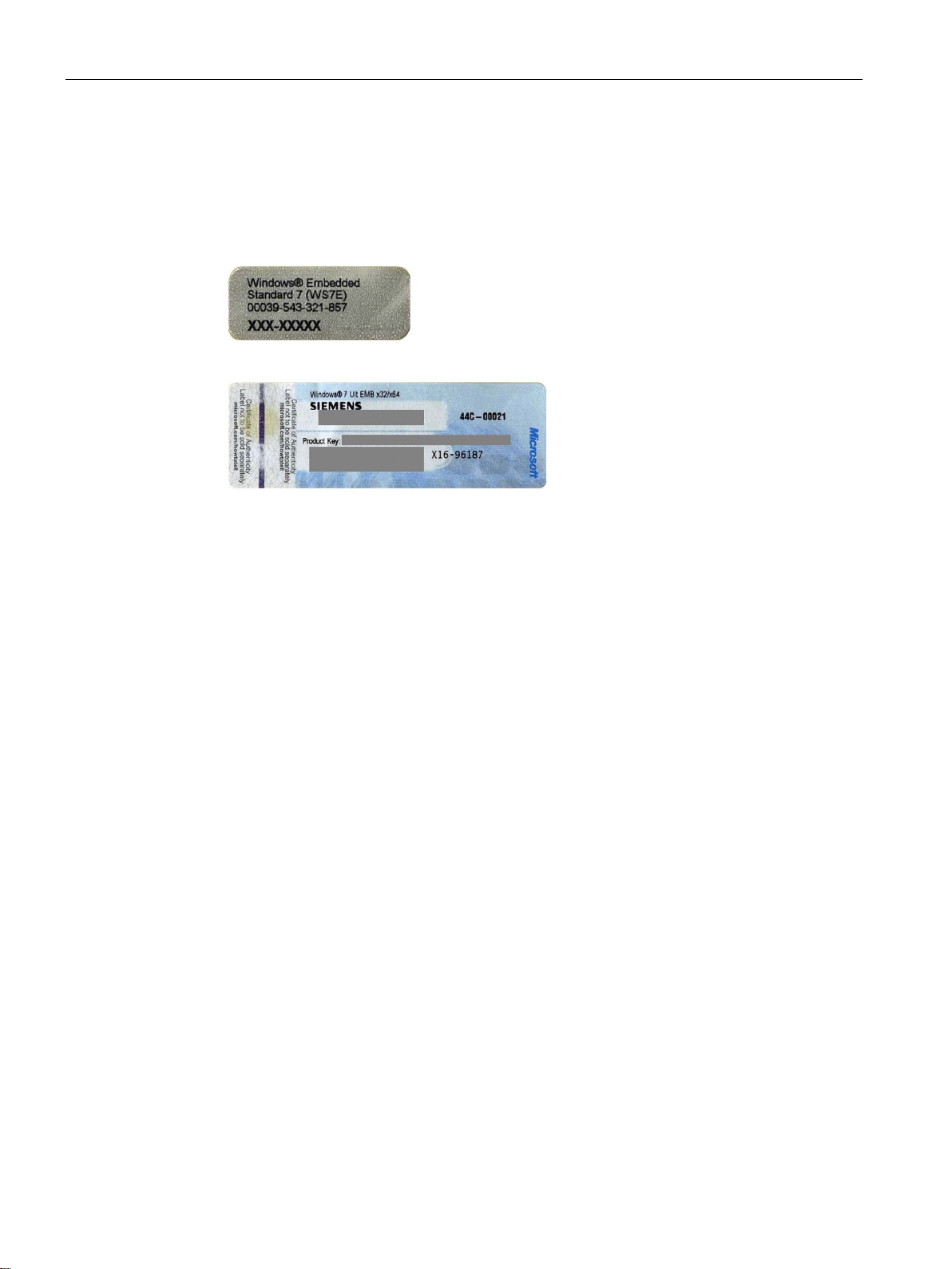
Example of a COA label
3.1 Preparing for installation
Microsoft Windows "Product Key" on the "Certificate of Authenticity" (COA):
The COA label is only attached to the rear of the device containing a Windows Embedded
Standard 7 or Windows 7 operating system.
● COA label of a device with Windows Embedded Standard 7 operating system
● COA label of a device with Windows 7 operating system
SIMATIC IPC227E
28 Operating Instructions, 11/2016, A5E35782395-AB
Installing and connecting the device
3.1.3
Permitted mounting positions
3.1 Preparing for installation
The following mounting positions are permitted:
● Horizontal mounting position
The horizontal mounting position is the preferred position.
● Vertical mounting position – upright mounting
Take into account the permitted temperature range for operation that depends on the
mounting position in accordance with the "Technical specifications (Page 99)" section.
Ensure that the following clearances measurements to another component or to a wall of a
housing are complied with:
● Below the device: ≥ 100 mm
● Above the device: ≥ 50 mm
SIMATIC IPC227E
Operating Instructions, 11/2016, A5E35782395-AB
29

Installing and connecting the device
3.1.4
Installing the cable strain relief
Procedure
Insert the metal plate of the
strain relief into the last
notch left and right.
Secure the strain relief on
the left and righ
ly with an M3x8 setscrew.
Secure the connection c
bles with cable ties to the
cable strain relief.
3.1 Preparing for installation
The cable strain relief plate carries the cables and prevents unintentional loosening of the
connector from the device. The cable strain relief is available as an accessory.
t respective-
a-
SIMATIC IPC227E
30 Operating Instructions, 11/2016, A5E35782395-AB
 Loading...