

Siemens SIMATIC IPC1047 Quick Install Manual
Gerät einbauen
Mounting the device
12
Gerät anschließen
Connecting the device
1.1
Vor Einbau und Inbetriebnahme – Before mounting and commissioning
WICHTIG: Beachten Sie alle dem Gerät beiliegenden Dokumente und die Betriebsanleitung, bevor
Sie das Gerät einbauen und anschließen. Die vollständige Dokumentation des Geräts finden Sie auf
der beiliegenden DVD "Documentation and Drivers" und im Internet
(http://www.siemens.de/simatic-ipc-doku-portal).
IMPORTANT: observe all documents enclosed with the devic e and the operating instructions manual
before mounting and connecting the device. You find the complete documentation of the devic e on
the enclosed „ Documentation and Driver s" DVD and on the internet
(http://www.siemens.com/simatic-ipc-doku-portal).
Das Handbuchsymbol weist auf detaillierte Informationen in der Betriebsanleitung hin.
The manual symbol refers to detailed information in the operating instructions.
VORSICHT
!
bedeutet, dass eine leichte Körperverletzung eintreten kann, wenn die entsprechenden
Vorsichtsmaßnahmen nicht getroffen werden.
CAUTION
!
with a safety aler t symbol, indicates that minor personal injury can result if proper precautions are
not taken.
Zulässige Einbaulagen – Valid Mounting positions
1.2
50 °C (Grundausbau- basic configuration)
40 °C (Maximalausbau - maximum configuration)
0 °C
Der Freiraum im Bereich der Lüftungsschlitze muss mindestens 50 mm betragen.
Hinweis zur Stromversorgung – Information about the power supply
2.1
Das Gerät ist ausschließlich für den Betrieb an geerdeten Stromversorgungsnetzen vorgesehen
(TN-Netze nach VDE 0100 Teil 100 bzw. IEC 60364-1). Der Betrieb über nicht geerdete oder über
Impedanz-geerdete Netze ist nicht erlaubt.
The device is solely intended for operation on grounded power supply systems ( TN systems
according to VDE 0100, Part 100, or IEC 60364 -1). It is not designed for operation on ungrounded
or impedance- grounded power net works.
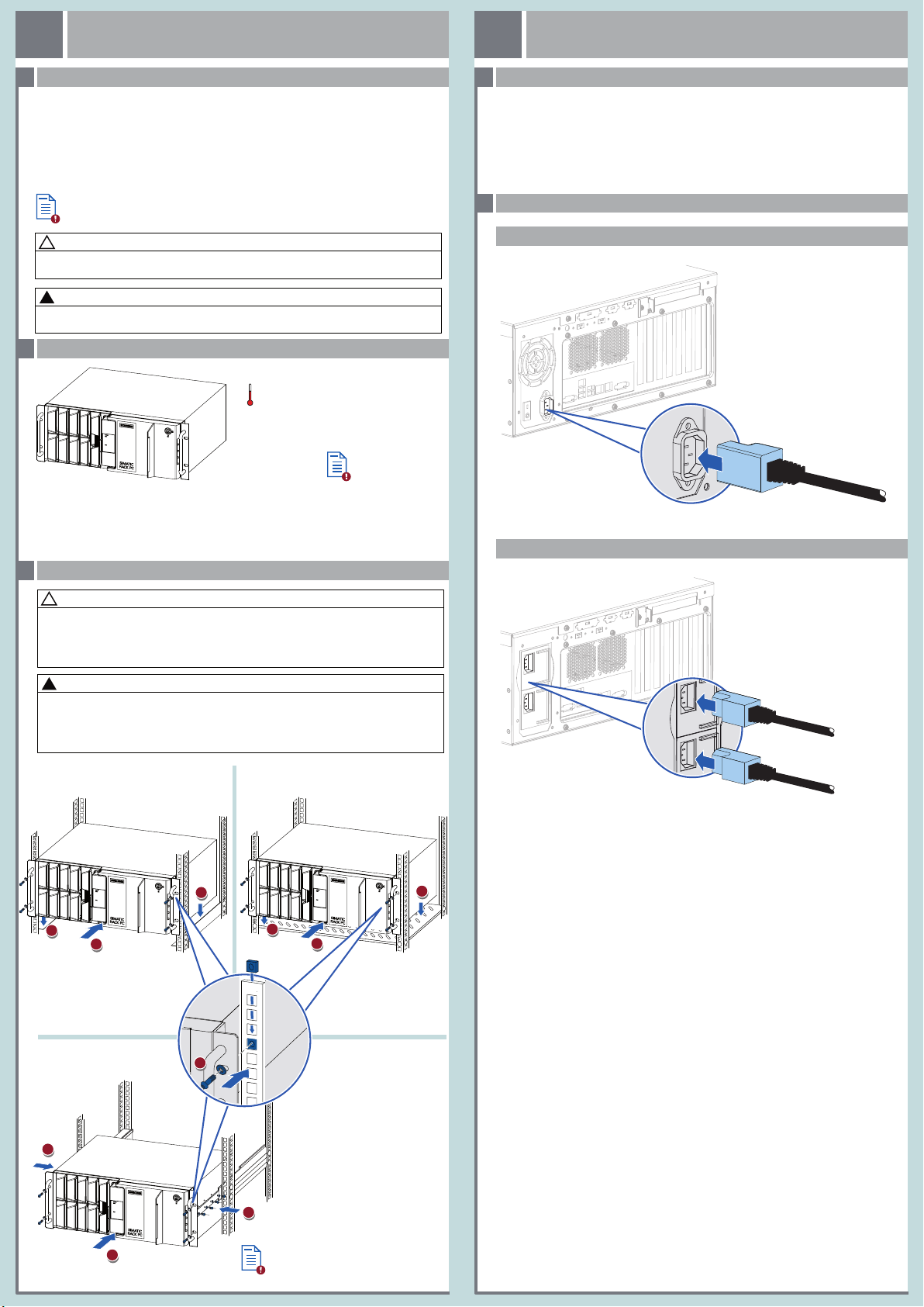
Stromversorgung anschließen – Connecting the power supply
2.2
Gerät ohne redundante Stromversorgung – Device without redundant power supply
At least 50 mm space has to be left free around the ventilation slots.
Gerät einbauen – Installing the device
1.3
VORSICHT
!
Gefahr d er Körper verletzung
Das Gerät ist zu schwer, um ausschließlich an den 19"-Halterungen der Front montiert zu werden.
Das Gerät kann herunterfallen, Personen verlet zen und beschädigt werden.
Befestigen Sie das Gerät zusätzlich. Die Befestigungsschrauben der Teleskopschienen dürfen
maximal 5 mm in das Gerät hineinragen.
CAUTION
!
Risk of physi cal injur y
The device is too heavy to be mounted exclusively with the 19 inch brackets of the front panel.
The device may fall down, injure people and get damaged.
Secure the device using additional measures. The mounting screws of the telescopic rails may not
protrude more than 5 mm into the device.
Montage mit Winkelprofilen
Mounting on angle brackets
1
2
1
Montage auf Geräteböden
Mounting on device bases
1
2
Gerät mit redundanter Stromversorgung – Device with redundant power supply
1
Montage mit Teleskopschienen
Mounting on telescopic rails
1
2
3
1
Gerät in Betrieb nehmen
Commissioning the device
3
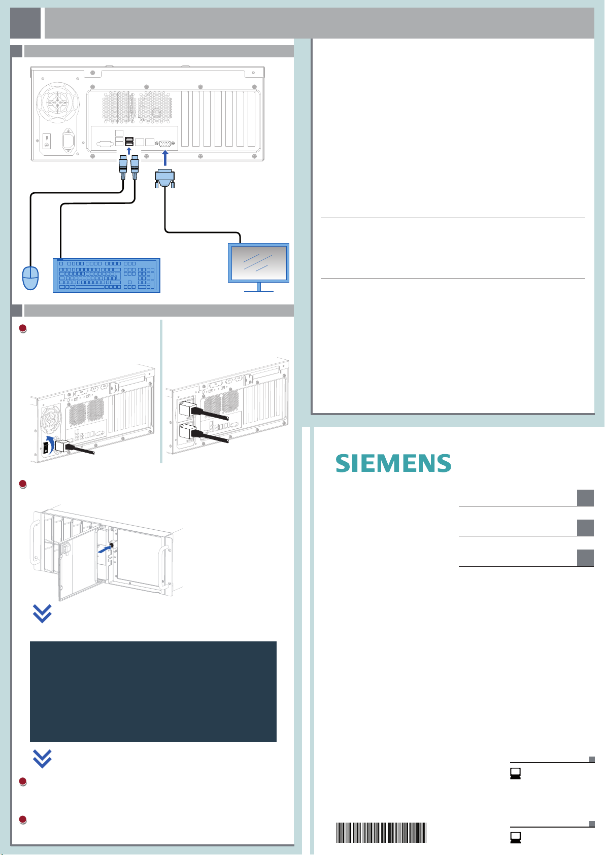
Maus, Tastatur, Monitor anschließen – Connecting mouse, keyboard, monitor
3.1
USB
VGA
Gerät einschalten – Switching on the device
3.2
Geräte ohne redundante Stromversorgung:
1
Schalten Sie den Ein- /Aus-Schalter
in Position "1".
Devices without redundant power supply:
Set the on/off switch to position "1".
Geräte mit redundanter Stromversorgung
besitzen keinen Ein-/Aus-Schalter.
Devices with redundant power supply do not
have an on/off switch.
Abbildungen
Das vorliegende Dokument enthält Abbildungen zu den beschriebenen Geräten und Zubehör.
Die Abbildungen können bezogen auf das geliefer te Gerät und Zubehör in Einzelheiten abweichen.
Illustrations
This document contains illustrations of the described devices and accessories.
The illustrations may deviate from the particularities of the delivered device and accessories.
Haftungsausschluss
Wir haben den Inhalt der Druckschrift auf Übereinstimmung mit der beschriebenen Hard- und
Software geprüft. Dennoch können Abweichungen nicht ausgeschlossen werden, so dass wir für
die vollständige Übereinstimmung keine Gewähr übernehmen. Die Angaben in dieser Druckschrif t
werden regelmäßig überprüft, notwendige Korrekturen sind in den nachfolgenden Auf lagen
enthalten.
Disclaimer of Liabi lity
We have reviewed the contents of this publication to ensure consistency with the hardware and
software described. Since variance cannot be precluded entirely, we cannot guarantee full
consistency. However, the information in this publication is reviewed regularly and any necessary
corrections are included in subsequent editions.
Siemens AG
Division Digital Factory
Postfach 48 48
90026 NÜRNBERG
2
Drücken Sie den Ein-Aus-Taster.
Press the on/of f button.
Self-Test
Version 2.17.1249. Copyright (C) 2016 Americ an Megatren ds, Inc.
Supermicro X10DRi/X10DRi-T Series BIOS Date: 09/13/2016 Ver: 2.1
CPU : Intel(R) Xeon(R) CPU E5 -2620 v4 @ 2.10GHz Speed: 2100MHz M emory 65 536MB
DDR4 2134MHZ
Press <DEL> or <ESC> to ente r setup.
3
Warten Sie bis die Meldung erlischt.
Wait for the message to disappear.
4
Folgen Sie den Anweisungen auf dem Bildschirm.
Follow the instructions on the screen.
SIMATIC
Industrial PC
SIMATIC IPC1047
Quick Install Guide
09/2018
A5E45118494-AA
Gerät einbauen
Mounting the device
Gerät anschließen
Connecting the device
Gerät in Betrieb nehmen
Commissioning the device
Technische Support-Zentrale
Central Technical Support
www.siemens.com/
automation/support
Reparatur und Ersatzteile
Service and spare parts
https://support.industry.
siemens.com/sc/de/en/sc
1
2
3
 Loading...