

Siemens SIMATIC Industrial Flat Panel IFP1500, SIMATIC Industrial Flat Panel IFP1900, SIMATIC Industrial Flat Panel IFP2200 Operating Instructions Manual

Industrial Flat Panel IFP1500, IFP1900,
IFP2200
___________________
___________________
___________________
___________________
___________________
___________________
___________________
___________________
___________________
___________________
SIMATIC
Industrial Monitors
Industrial Flat Panel IFP1500,
IFP1900, IFP2200
Operating Instructions
06/2014
A5E31298376
-AB
Preface
Overview
1
Safety information
2
Installing and connecting the
device
3
Commissioning the device
4
Operating the device
5
Maintaining and servicing
your device
6
Technical information
7
Technical Support
A
List of abbreviations
B
Siemens AG
Industry Sector
Postfach 48 48
90026 NÜRNBERG
GERMANY
A5E31298376-AB
Ⓟ
06/2014 Subject to change
Copyright © Siemens AG 2014.
All rights reserved
Legal information
Warning notice system
This manual contains notices you have to observe in order to ensure your personal safety, as well as to prevent
damage to property. The notices referring to your personal safety are highlighted in the manual by a safety alert
symbol, notices referring only to property damage have no safety alert symbol. These notices shown below are
graded according to the degree of danger.
DANGER
indicates that death or severe personal injury will result if proper precautions are not taken.
WARNING
indicates that death or severe personal injury may result if proper precautions are not taken.
CAUTION
indicates that minor personal injury can result if proper precautions are not taken.
NOTICE
indicates that property damage can result if proper precautions are not taken.
If more than one degree of danger is present, the warning notice representing the highest degree of danger will
be used. A notice warning of injury to persons with a safety alert symbol may also include a warning relating to
property damage.
Qualified Personnel
The product/system described in this documentation may be operated only by
personnel qualified
for the specific
task in accordance with the relevant documentation, in particular its warning notices and safety instructions.
Qualified personnel are those who, based on their training and experience, are capable of identifying risks and
avoiding potential hazards when working with these products/systems.
Proper use of Siemens products
Note the following:
WARNING
Siemens products may only be used for the applications described in the catalog and in the relevant technical
documentation. If products and components from other manufacturers are used, these must be recommended
or approved by Siemens. Proper transport, storage, installation, assembly, commissioning, operation and
maintenance are required to ensure that the products operate safely and without any problems. The permissible
ambient conditions must be complied with. The information in the relevant documentation must be observed.
Trademarks
All names identified by ® are registered trademarks of Siemens AG. The remaining trademarks in this publication
may be trademarks whose use by third parties for their own purposes could violate the rights of the owner.
Disclaimer of Liability
We have reviewed the contents of this publication to ensure consistency with the hardware and software
described. Since variance cannot be precluded entirely, we cannot guarantee full consistency. However, the
information in this publication is reviewed regularly and any necessary corrections are included in subsequent
editions.

Industrial Flat Panel IFP1500, IFP1900, IFP2200
Operating Instructions, 06/2014, A5E31298376-AB
3
Preface
These operating instructions contain all the information you need for commissioning and
operation of the SIMATIC Industrial Flat Panel IFP.
It is intended both for programming and testing personnel who commission the device and
connect it with other units (automation systems, programming devices), as well as for service
and maintenance personnel who install add-ons or carry out fault/error analyses.
Basic knowledge required
A solid background in personal computers and Microsoft operating systems is required to
understand this manual. General knowledge in the field automation control engineering is
recommended.
Scope of the operating instructions
These operating instructions apply to all IFP1500, IFP1900 and IFP2200 Industrial Flat
Panels with the order numbers 6AV7863-....
Scope of this documentation
The SIMATIC Industrial Flat Panel is supplied with the following documents:
● In printed form: Quick Install Guide SIMATIC IFP1500, IFP1900, IFP2200, Installation
and Commissioning Instructions
● Electronically as PDF file on the "Documentation and Drivers" CD/DVD:
– IFP1500, IFP1900, IFP2200 Operating Instructions
– Operating Manual SIMATIC IPC Wizard
You can find the operating manual in the IPC Wizard installation directory after
installing the IPC Wizard.
Conventions
In these operating instructions, the SIMATIC IFP is also referred to as "Flat Panel" or
"device".
At some places in these operating instructions, the general term "Windows Embedded
Standard" is used to refer to "Windows Embedded Standard 2009" and "Windows
Embedded Standard 7". "Windows 7" is used as an abbreviation for "Windows 7 Ultimate".
A touch device generally refers to a device with a touch screen, as opposed to a pure
"display device". Touch screen is the general term for a capacitive multi-touch screen and
resistive single touch screen.

Preface
Industrial Flat Panel IFP1500, IFP1900, IFP2200
4 Operating Instructions, 06/2014, A5E31298376-AB
Figures
This manual contains figures of the described devices. The supplied device may differ in
some details from the figures. Within some of the figures, one device is used to represent all
Industrial Flat Panels.
History
The following earlier release versions of these operating instructions have been published:
Edition
Comment
09/2012
First Edition
06/2014
Description of devices with capacitive multi-touch screen

Industrial Flat Panel IFP1500, IFP1900, IFP2200
Operating Instructions, 06/2014, A5E31298376-AB
5
Table of contents
Preface ................................................................................................................................................... 3
1 Overview................................................................................................................................................. 9
1.1 Product description ........................................................................................................................ 9
1.2 Scope of delivery.......................................................................................................................... 11
1.3 Construction of the devices .......................................................................................................... 12
1.3.1 IFP1900, IFP2200 Multitouch ...................................................................................................... 12
1.3.2 IFP1500, IFP1900, IFP2200 Touch ............................................................................................. 14
1.3.3 IFP1500 Touch/Key ..................................................................................................................... 15
1.3.4 Interfaces ..................................................................................................................................... 16
1.3.4.1 Standard versions ........................................................................................................................ 16
1.3.4.2 Extended versions ....................................................................................................................... 16
1.4 Accessories .................................................................................................................................. 17
2 Safety information ................................................................................................................................. 19
2.1 General safety instructions .......................................................................................................... 19
2.2 Notes about usage ....................................................................................................................... 22
3 Installing and connecting the device ...................................................................................................... 25
3.1 Preparing for installation .............................................................................................................. 25
3.1.1 Checking the delivery package .................................................................................................... 25
3.1.2 Permitted mounting positions ....................................................................................................... 27
3.1.3 Checking clearances .................................................................................................................... 29
3.1.4 Preparing the mounting cutout ..................................................................................................... 30
3.1.5 Labeling the function keys ........................................................................................................... 31
3.2 Mounting the device ..................................................................................................................... 33
3.2.1 Notes on installation ..................................................................................................................... 33
3.2.2 Position of the mounting clips or brackets ................................................................................... 34
3.2.3 Fastening the device with mounting clamps or latch fasteners ................................................... 35
3.3 Connecting the device ................................................................................................................. 37
3.3.1 Overview ...................................................................................................................................... 37
3.3.2 Notes on connection .................................................................................................................... 39
3.3.3 Connecting the PE conductor or equipotential bonding .............................................................. 39
3.3.4 Connecting the power supply ....................................................................................................... 41
3.3.4.1 Connecting the DC power supply ................................................................................................ 41
3.3.4.2 Connecting an AC power supply .................................................................................................. 43
3.3.5 Connecting the device to a PC .................................................................................................... 45
3.3.5.1 Standard version .......................................................................................................................... 45
3.3.5.2 Extended version ......................................................................................................................... 45
3.3.6 Connecting a USB device ............................................................................................................ 46
3.3.7 Securing the cables ..................................................................................................................... 47

Table of contents
Industrial Flat Panel IFP1500, IFP1900, IFP2200
6 Operating Instructions, 06/2014, A5E31298376-AB
4 Commissioning the device .................................................................................................................... 49
4.1 General information on commissioning ....................................................................................... 49
4.2 SIMATIC IPC Wizard .................................................................................................................. 50
4.2.1 Product description ..................................................................................................................... 50
4.2.2 System requirements .................................................................................................................. 50
4.2.3 Installing IPC Wizard ................................................................................................................... 52
5 Operating the device ............................................................................................................................. 55
5.1 Operator input options ................................................................................................................. 55
5.2 Operating a device with resistive single touch screen ................................................................ 56
5.3 Operating a device with capacitive multi-touch screen ............................................................... 57
5.4 Operating a Touch/Key device .................................................................................................... 59
5.5 IPC Wizard functions ................................................................................................................... 63
5.5.1 Overview ..................................................................................................................................... 63
5.5.2 IPC Wizard features for devices with resistive single touch screen............................................ 63
5.5.2.1 Calibrating the touch screen ....................................................................................................... 63
5.5.2.2 Standard calibration .................................................................................................................... 64
5.5.2.3 Extended calibration .................................................................................................................... 65
5.5.2.4 Extended Touch touch functionality ............................................................................................ 66
5.5.2.5 Using the on-screen keyboard for Windows 7 and Windows Embedded Standard 7/P ............. 67
5.5.2.6 Using the on-screen keyboard for Windows Embedded Standard 7/E ...................................... 68
6 Maintaining and servicing your device ................................................................................................... 69
6.1 Cleaning the device ..................................................................................................................... 69
6.2 Spare parts and repairs ............................................................................................................... 70
6.3 Recycling and disposal ............................................................................................................... 70
7 Technical information ............................................................................................................................ 71
7.1 Certificates and approvals........................................................................................................... 71
7.1.1 Programmable logic controllers................................................................................................... 74
7.2 Directives and declarations ......................................................................................................... 74
7.2.1 ESD guideline ............................................................................................................................. 74
7.2.2 Electromagnetic compatibility...................................................................................................... 76
7.3 Dimension drawings .................................................................................................................... 77
7.3.1 Dimension drawing of the IFP1500 Monitor and Touch .............................................................. 77
7.3.2 Dimension drawing of the IFP1900 Multitouch ........................................................................... 78
7.3.3 Dimension drawing of the IFP1900 Monitor and Touch .............................................................. 79
7.3.4 Dimension drawing of the IFP2200 Multitouch ........................................................................... 80
7.3.5 Dimension drawing of the IFP2200 Monitor and Touch .............................................................. 81
7.3.6 Dimension drawing of the IFP1500 Touch/Key........................................................................... 82
7.3.7 Dimensions for labeling strips ..................................................................................................... 82
7.4 Rating plate ................................................................................................................................. 83

Table of contents
Industrial Flat Panel IFP1500, IFP1900, IFP2200
Operating Instructions, 06/2014, A5E31298376-AB
7
7.5 Technical specifications ............................................................................................................... 84
7.5.1 General technical specifications .................................................................................................. 84
7.5.2 Ambient conditions ....................................................................................................................... 86
7.5.2.1 Transport and storage conditions ................................................................................................ 86
7.5.2.2 Operating conditions .................................................................................................................... 87
7.5.2.3 Information on insulation tests, protection class and degree of protection .................................. 90
7.6 Interface description ..................................................................................................................... 91
7.6.1 24 V DC Power Supply ................................................................................................................ 91
7.6.2 DVI-D interface............................................................................................................................. 92
7.6.3 DisplayPort ................................................................................................................................... 93
7.6.4 USB interface, Type B ................................................................................................................. 94
7.6.5 USB hub, Type A ......................................................................................................................... 94
A Technical Support ................................................................................................................................. 95
A.1 Service and support ..................................................................................................................... 95
B List of abbreviations .............................................................................................................................. 97
Glossary ............................................................................................................................................... 99
Index................................................................................................................................................... 101

Table of contents
Industrial Flat Panel IFP1500, IFP1900, IFP2200
8 Operating Instructions, 06/2014, A5E31298376-AB
Industrial Flat Panel IFP1500, IFP1900, IFP2200
Operating Instructions, 06/2014, A5E31298376-AB
9
1
1.1
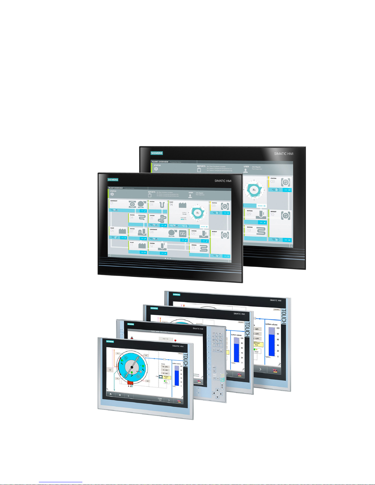
Product description
SIMATIC Industrial Flat Panels are LCD monitors suitable for industrial use with a brilliant
TFT display which can be connected to all SIMATIC IPCs as well as almost all generally
available PCs.

Overview
1.1 Product description
Industrial Flat Panel IFP1500, IFP1900, IFP2200
10 Operating Instructions, 06/2014, A5E31298376-AB
Features of SIMATIC Industrial Flat Panels
● Rugged front
● Brilliant TFT display with a wide reading angle;
Resistive single touch screen in sizes 15", 19" and 22"
Capacitive multi-touch screen available in sizes 19" and 22"
● Available as pure display device (monitor) or touch device
● Can be placed up to 5 m from the IPC
● DVI-D and DisplayPort V1.1 interface
● Multi-monitoring support
● Backlighting can be dimmed via software
● 24 V DC power supply
● Degree of protection IP65 in installed state
● Enclosure type: Front face only Type 4X/Type 12 (indoor use only)
● Up to 16 million colors
Additional features of the Extended versions
● Up to 30 m away from PC possible via DVI
● Power supply (with USB) 24 V DC and 100-240 V AC
● 2 USB ports
● Also available as touch/key version with front USB interface
Overview
1.2 Scope of delivery
Industrial Flat Panel IFP1500, IFP1900, IFP2200
Operating Instructions, 06/2014, A5E31298376-AB
11
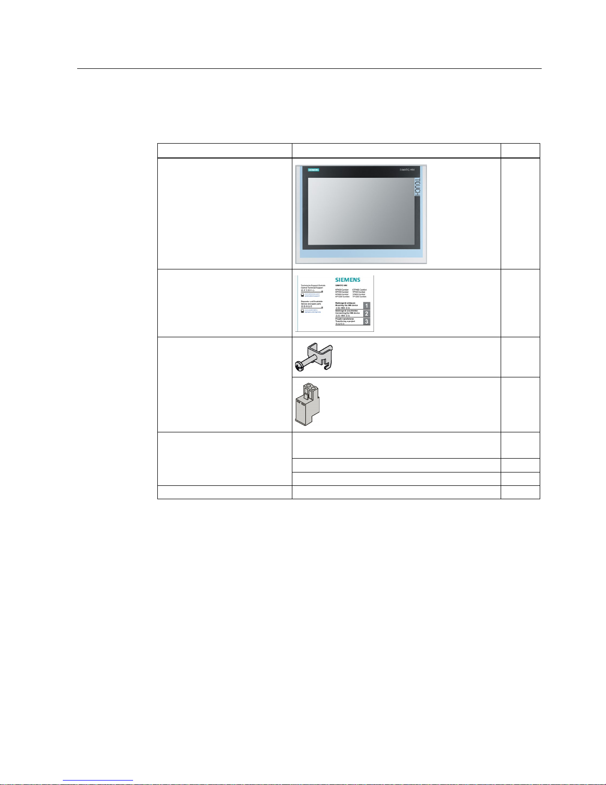
1.2
Scope of delivery
The product package includes the following components:
Name
Figure
Number
Industrial Flat Panel
1
Installation instructions
(Quick Install Guide)
1
"Mounting clamps and power
supply plugs" accessory kit
12
1
"Connecting cables" accessory kit DVI connecting cable
2 m in length, for commissioning
1
USB connecting cable, 2 m 1
1
Power supply cable 230 V AC 2
1
"Documentation and Drivers" CD
1
1
Not with standard display device (monitor)
2
Only for devices with AC power supply
Overview
1.3 Construction of the devices
Industrial Flat Panel IFP1500, IFP1900, IFP2200
12 Operating Instructions, 06/2014, A5E31298376-AB
1.3
Construction of the devices
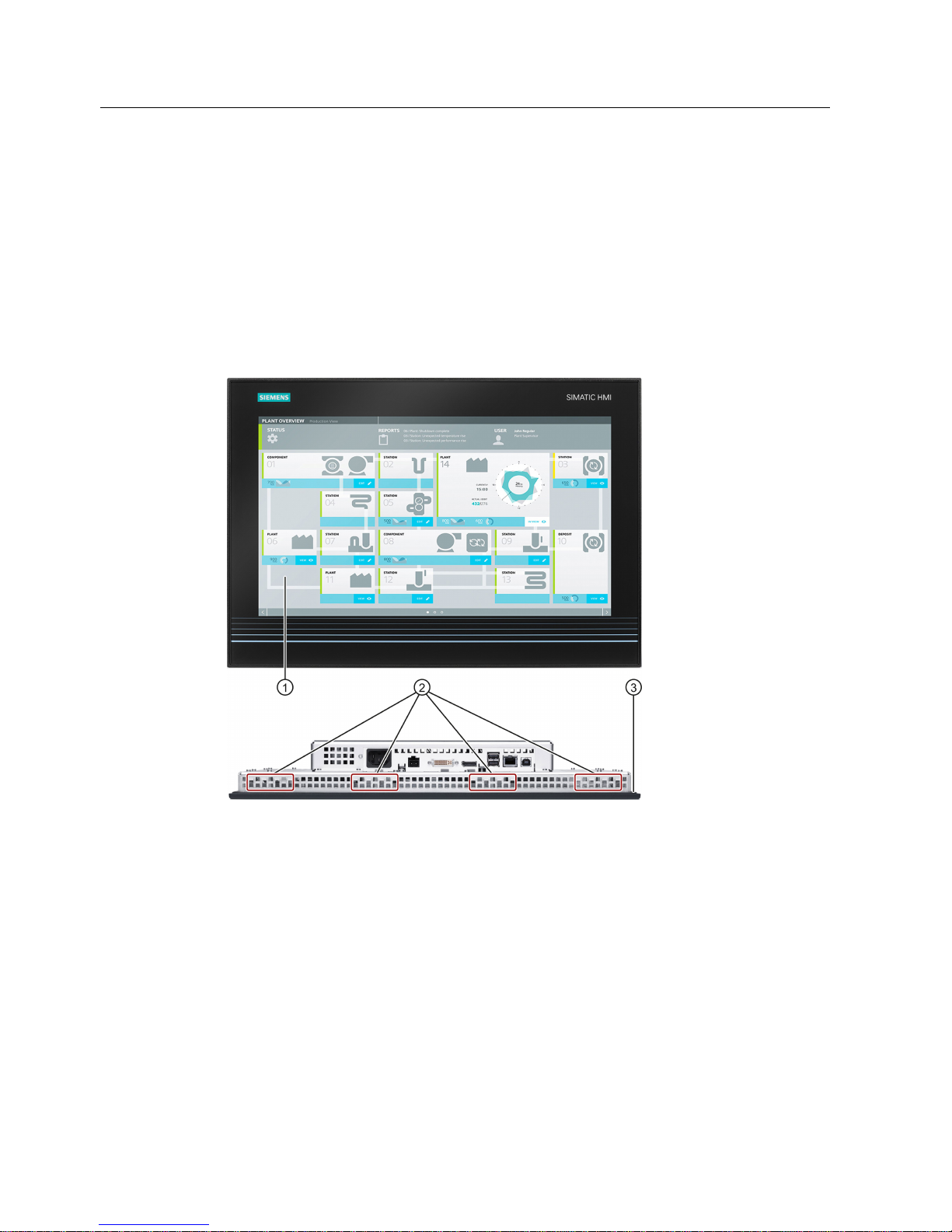
1.3.1
IFP1900, IFP2200 Multitouch
This section describes the design of the multi-touch devices, using the IFP1900 Multitouch
as an example.
Front view and side view
①
Display/touch screen
②
Recesses for mounting clamps
③
Mounting seal
Overview
1.3 Construction of the devices
Industrial Flat Panel IFP1500, IFP1900, IFP2200
Operating Instructions, 06/2014, A5E31298376-AB
13
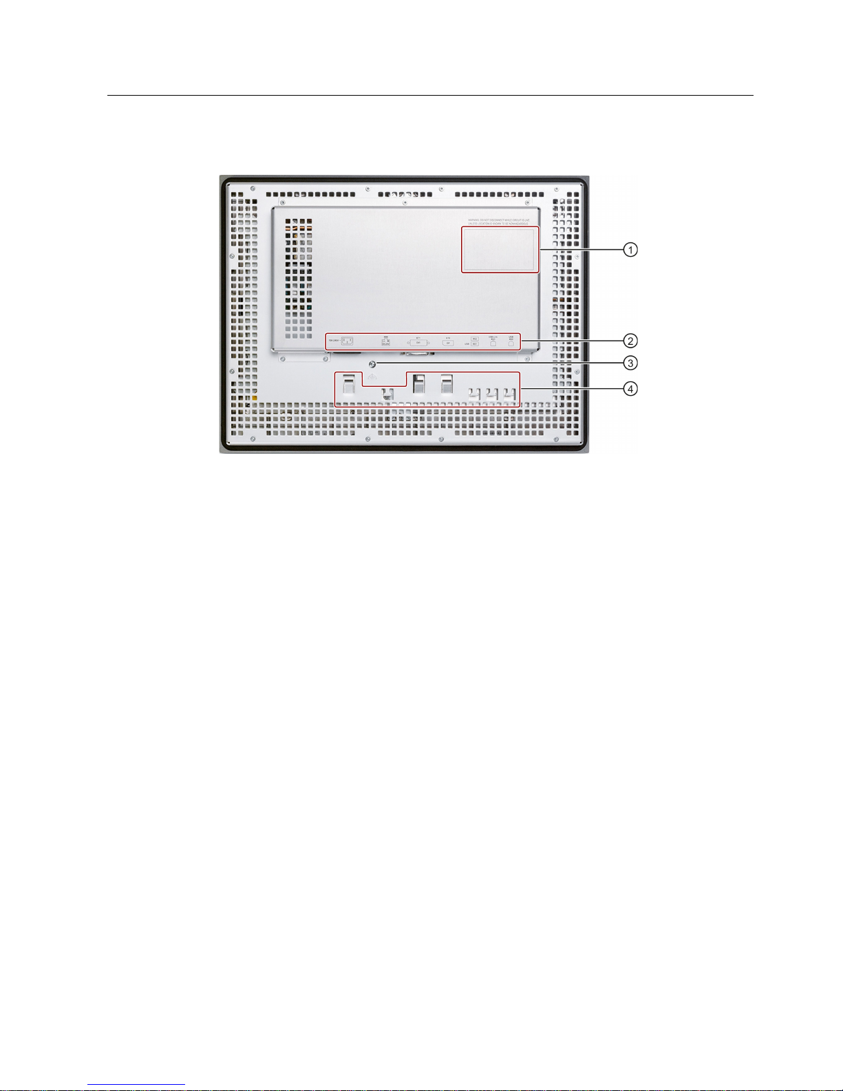
Rear view
①
Rating plate
②
Interface name
③
Equipotential bonding
④
Retaining elements for strain relief of the connecting cables

Overview
1.3 Construction of the devices
Industrial Flat Panel IFP1500, IFP1900, IFP2200
14 Operating Instructions, 06/2014, A5E31298376-AB
1.3.2
IFP1500, IFP1900, IFP2200 Touch
This section describes the design of the monitor and touch devices, using the IFP1500
Touch as an example.
Front view and side view
①
Display/touch screen
②
Recesses for mounting clamps
③
Mounting seal
Rear view
See section "IFP1900, IFP2200 Multitouch".
Overview
1.3 Construction of the devices
Industrial Flat Panel IFP1500, IFP1900, IFP2200
Operating Instructions, 06/2014, A5E31298376-AB
15
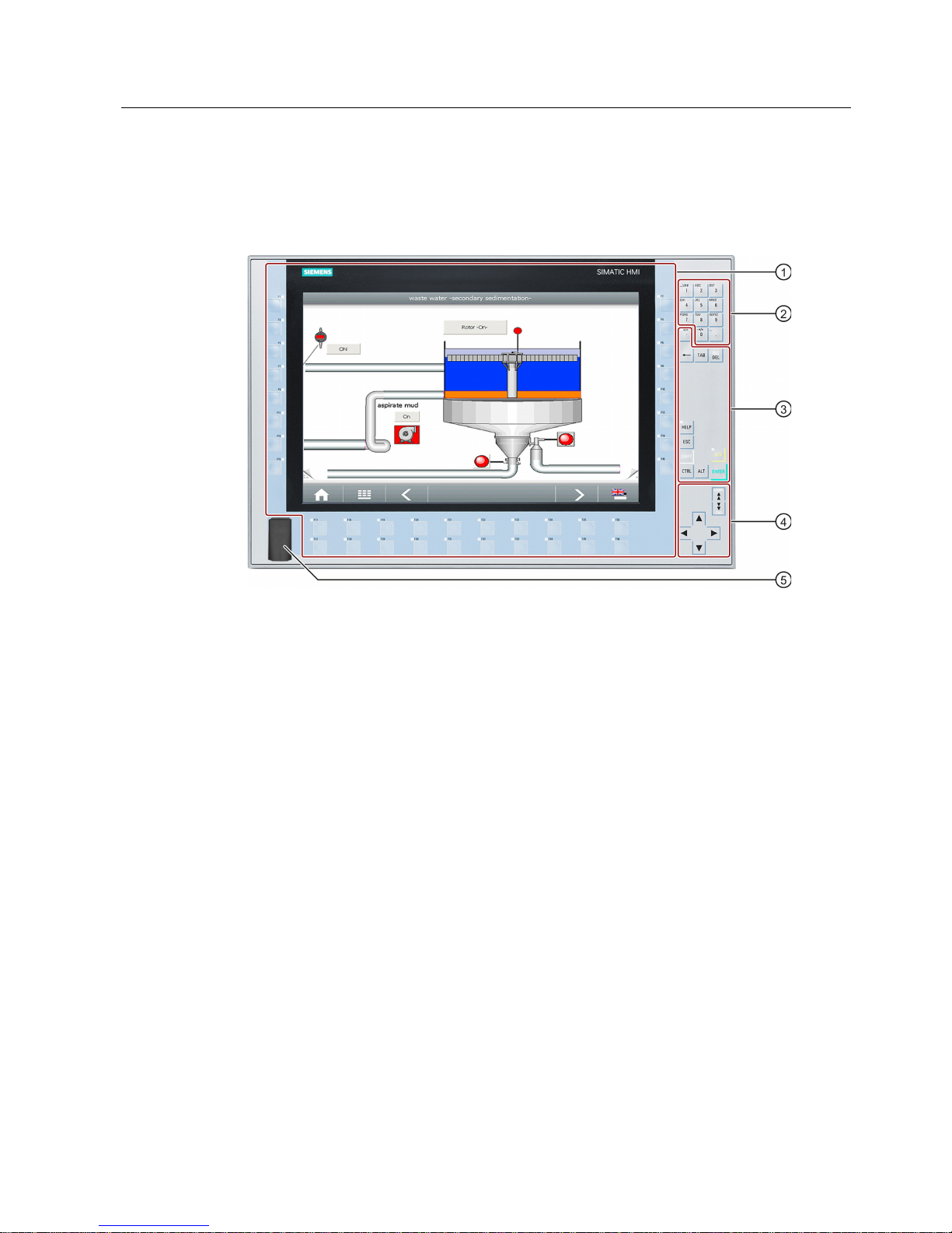
1.3.3
IFP1500 Touch/Key
Front view
①
Display and function keys with LED
②
Alphanumeric keys
③
Control keys
④
Cursor keys
⑤
USB port
Overview
1.3 Construction of the devices
Industrial Flat Panel IFP1500, IFP1900, IFP2200
16 Operating Instructions, 06/2014, A5E31298376-AB
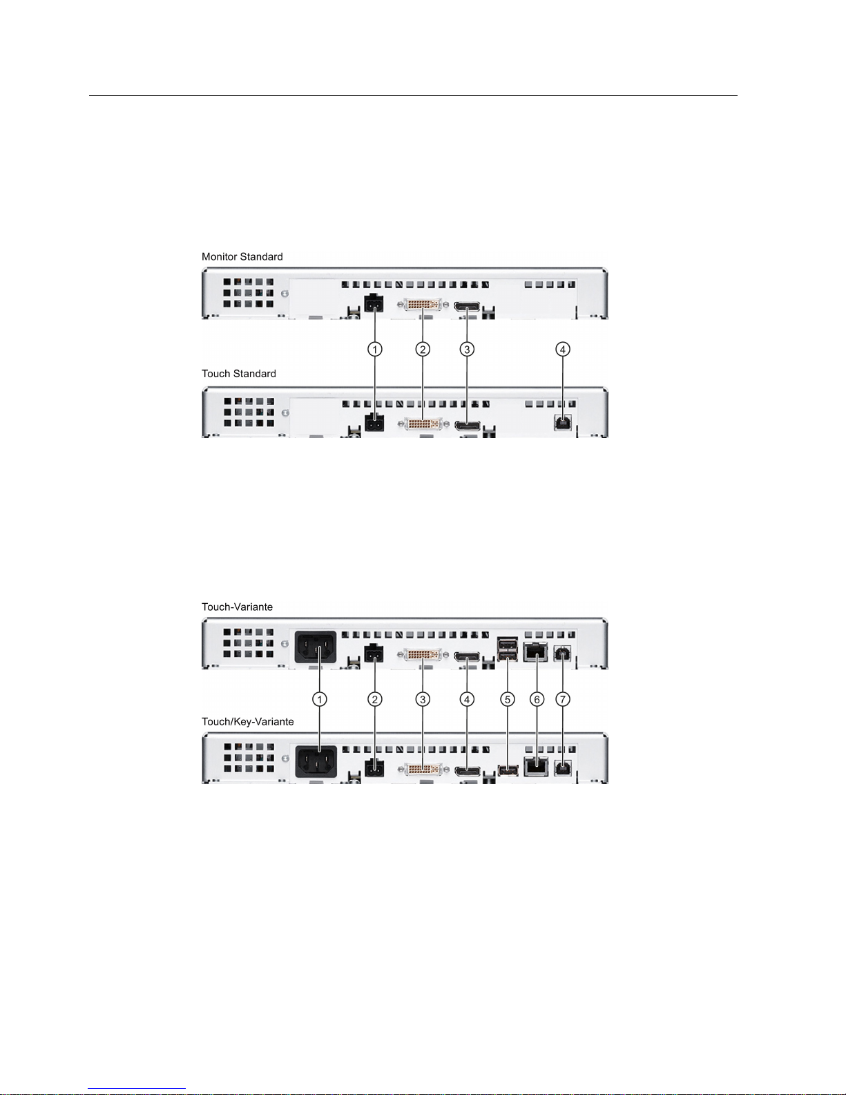
1.3.4
Interfaces
1.3.4.1
Standard versions
①
X80 connector for 24 V DC power supply
②
X71 DVI-D interface
③
X70 DisplayPort interface
④
X60 USB Type B
1.3.4.2
Extended versions
①
Connection for 100 to 240 V AC power
supply
⑤
X61/X62 USB Type A
②
X80 connector for 24 V DC power supply
⑥
X63 USB link interface
③
X71 DVI-D interface
⑦
X60 USB Type B
④
X70 DisplayPort interface
Overview
1.4 Accessories
Industrial Flat Panel IFP1500, IFP1900, IFP2200
Operating Instructions, 06/2014, A5E31298376-AB
17
1.4
Accessories
This section contains the number of accessories available at the time of publication of the
operating instructions. You will find additional accessories on the Internet at:
● Industry Mall (http://mall.automation.siemens.com)
● Expansion components and accessories (http://www.automation.siemens.com/mcms/pc-
based-automation/en/industrial-pc/expansion_components_accessories)
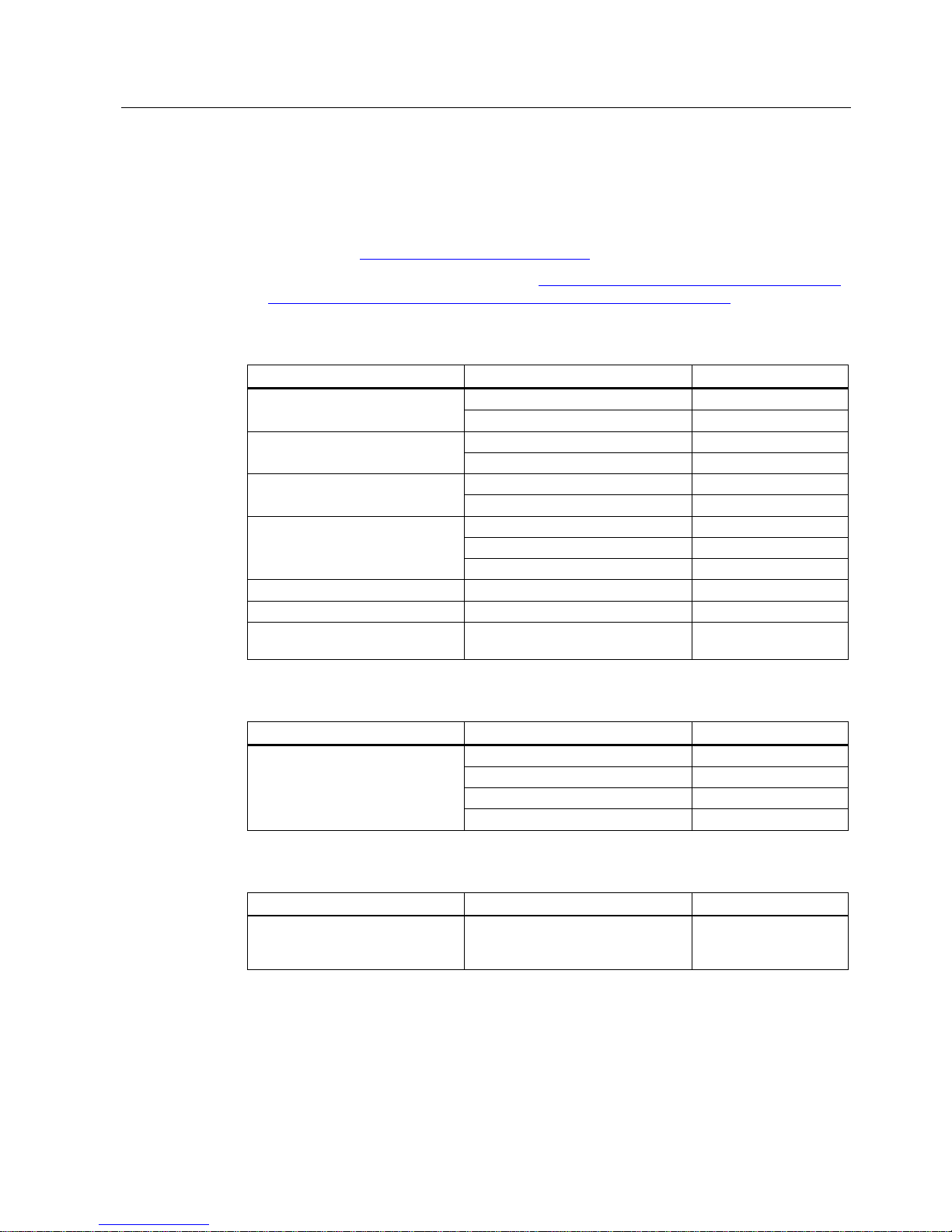
All Industrial Flat Panels
Name
Specification
Order number
DVI line
3 m long
6AV7860-0BH30-0AA0
5 m long
6AV7860-0BH50-0AA0
DisplayPort line
3 m long
6AV7860-0DH30-0AA0
5 m long
6AV7860-0DH50-0AA0
USB line
3 m long
6AV7860-0CH30-0AA0
5 m long
6AV7860-0CH50-0AA0
Protective foil for the touch screen
15"
6AV2124-6QJ00-0AX0
19"
6AV2124-6UJ00-0AX0
22"
6AV2124-6XJ00-0AX0
Service pack - mounting clamps
20 pieces
6AV6671-8XK00-0AX3
Service pack - latch fasteners
2 x 8 latch fasteners
6AV7672-1JC00-0AA0
Touch pen only for devices with resistive single
touch screen
6AV7672-1JB00-0AA0
Extended version
Name
Specification
Order number
Cable set (DVI/USB cable)
10 m long
6AV7860-1EX21-0AA1
15 m long
6AV7860-1EX21-5AA1
20 m long
6AV7860-1EX22-0AA1
30 m long
6AV7860-1EX23-0AA1
Touch/Key Extended version
Name
Order number
Film for labeling the function keys
(slide-in labels)
Print templates for the slide-in labels
are available on the "Documentation
and Drivers" CD/DVD.
6AV7672-0DA00-0AA0

Overview
1.4 Accessories
Industrial Flat Panel IFP1500, IFP1900, IFP2200
18 Operating Instructions, 06/2014, A5E31298376-AB

Industrial Flat Panel IFP1500, IFP1900, IFP2200
Operating Instructions, 06/2014, A5E31298376-AB
19
2
2.1
General safety instructions
Open equipment and the Machinery Directive
WARNING
The device constitutes open equipment
The device constitutes open equipment. This means that the device may only be installed
in enclosures or cabinets which provide front access for operating the device.
Access to the enclosure or cabinet in which the device is installed should only be possible
by means of a key or tool and for trained and authorized personnel.
Electrocution risk when control cabinet is open
When you open the control cabinet, there may be a dangerous voltage at certain areas or
components.
Touching these areas or components can cause electrocution.
Always disconnect the cabinet from the mains before opening it.
The device may only be used in machines which comply with the Machinery Directive
The Machinery Directive specifies precautions to be taken when commissioning and
operating machinery within the European Economic Area.
Failure to follow these precautions is a breach of the Machinery Directive. Such failure may
also cause personal injury and damage depending on the machine operated.
The machine in which the HMI device is to be operated must conform to Directive
2006/42/EC.

Safety information
2.1 General safety instructions
Industrial Flat Panel IFP1500, IFP1900, IFP2200
20 Operating Instructions, 06/2014, A5E31298376-AB
Hazardous areas
When operating the HMI device in hazardous areas the following warning applies.
WARNING
Explosion Hazard
Do not disconnect while circuit is live unless area is known to be non-hazardous.
Substitution of components may impair suitability for Class I, Division 2 or Zone 2.
Risque d'Explosion
Ne pas déconnecter pendant que le circuit est sous tension, sauf si la zone est nondangereuse. Le remplacement de composants peut compromettre leur capacité à satisfaire
à la Classe I, Division 2 ou Zone 2.
High frequency radiation
NOTICE
Unwanted operating states
High-frequency radiation, for example from cellular phones, interferes with device functions
and can cause device malfunction.
This causes injury and damages the system.
Avoid high-frequency radiation:
• Remove the sources of radiation from the vicinity of the device.
• Switch off radiating devices.
• Reduce the radio output of radiating devices.
• Observe the information on electromagnetic compatibility (Page 87).

Safety information
2.1 General safety instructions
Industrial Flat Panel IFP1500, IFP1900, IFP2200
Operating Instructions, 06/2014, A5E31298376-AB
21
Industrial Security
Siemens offers products and solutions with Industrial Security functions that support the safe
operation of equipment, solutions, machines, devices and/or networks. They are important
components in a comprehensive Industrial Security concept. As a result the products and
solutions from Siemens are constantly evolving. Siemens recommends obtaining regular
information regarding product updates.
For safe operation of Siemens products and solutions appropriate protective measures (e.g.,
cell protection concept) must be taken and each component must be integrated in a
comprehensive Industrial Security concept, which corresponds with the current state of
technology. The products of other manufacturers need to be taken into consideration if they
are also used. You can find addition information on Industrial Security under
(http://www.siemens.com/industrialsecurity).
Sign up for our product-specific newsletter to receive the latest information on product
updates. For more information, see under (http://www.siemens.de/automation/csi_en_WW).
Disclaimer for third-party software updates
This product includes third-party software. Siemens AG only provides a warranty for
updates/patches of the third-party software, if these have been distributed as part of a
Siemens software update service contract or officially released by Siemens AG. Otherwise,
updates/patches are undertaken at your own risk. You can find more information about our
Software Update Service offer on the Internet at Software Update Service
(http://www.automation.siemens.com/mcms/automation-software/en/software-update-
service/Pages/Default.aspx).
Notes on protecting administrator accounts
A user with administrator privileges has extensive access and manipulation options in the
system.
Therefore, ensure there are adequate safeguards for protecting the administrator accounts
to prevent unauthorized changes. To do this, use secure passwords and a standard user
account for normal operation. Other measures, such as the use of security policies, should
be applied as needed.

Safety information
2.2 Notes about usage
Industrial Flat Panel IFP1500, IFP1900, IFP2200
22 Operating Instructions, 06/2014, A5E31298376-AB
2.2
Notes about usage
NOTICE
Device is approved for indoor use only
The device may be damaged if operated outdoors.
• "Indoor use only"
• Operate the device indoors only.
Industrial applications
The device is designed for industrial use. It conforms to the following standards:
● Requirements of the emission standard for industrial environments, EN 61000-6-4: 2007
● Requirements for interference immunity EN 61000-6-2: 2005
● Immunity to interference acc. to EN 55024
● Radio interference suppression acc. to EN 55022, Class B
Use in residential areas
Note
Device is not intended for use in residential areas
The device is not
intended for use in residential areas. Operating the device in residential
areas can affect radio or TV reception.
If you operate the device in a residential area, you must ensure conformance to Class B
limits according to EN 55011 regarding the emission of radio interference.
Suitable measures for achieving the degree of noise suppression for Limit Class B include,
for example:
● Installation of the device in grounded control cabinets
● Use of filters in electrical supply lines
Individual acceptance is required.

Safety information
2.2 Notes about usage
Industrial Flat Panel IFP1500, IFP1900, IFP2200
Operating Instructions, 06/2014, A5E31298376-AB
23
Risk analysis and measures
WARNING
Hazards emanating from unprotected machines or plants
The results of a risk analysis can reveal any hazards emanating from unprotected
machinery. Such hazards may pose a risk of personal injury.
You can prevent personal injury caused by hazards as specified in the risk analysis by
taking the following measures:
• Installing additional protective devices on machinery and plants. In particular, it must
also be ensured that the programming, configuration and wiring of all I/Os used takes
place in accordance with the safety performance (SIL, PL or Cat.) identified by the
requisite risk analysis.
• Use of the device in accordance with its intended purpose, which can be verified by
means of a system function test. This test can detect programming, configuration and
wiring errors.
• Documentation of the test results, which must be entered in the relevant safety reports if
required.
Environment
NOTICE
Ambient conditions and chemical resistance
Ambient conditions not suited for the device can adversely affect operation. Chemical
agents, such as detergents or operating material, can change the color, shape and
structure of the device surface. The device may be damaged. This may lead to
malfunctions.
For this reason, the following precautionary measures should be taken:
• Only operate the device in closed rooms. Failure to comply with these instructions will
render the warranty null and void.
• Only operate the device in the ambient conditions specified in the technical
specifications.
• Protect the device against dust, moisture and heat.
• The device may not be used in harsh operating environments, such as areas subject to
acidic vapors or gases, without additional protective measures (e.g. a clean air supply).
• Only use suitable detergents. Only use suitable detergents. Read the information about
Chemical resistance of the HMI devices and industrial PCs
(http://support.automation.siemens.com/WW/view/en/39718396) on the Internet.

Safety information
2.2 Notes about usage
Industrial Flat Panel IFP1500, IFP1900, IFP2200
24 Operating Instructions, 06/2014, A5E31298376-AB
TFT displays
NOTICE
Burn-in effect and backlight
A permanent picture with bright images can result in a burn-in effect. The longer the same
content is displayed on the screen, the longer it will take for the burn-in effect to disappear.
Screen savers that use active black when the backlight is on reduce the burn-in effect. The
brightness of the backlight decreases incrementally during operational life.
• Activate the screen saver, for example, "starfield simulation".
You can extend the service life of the display and the backlight with the following measures:
• Reduce the backlight.
• Pay attention to the length of time the backlight is activated.
Additional information is available in the section "General Technical Specifications".
Defective pixels in the display
The manufacturing process of modern displays does not currently guarantee that all pixels of
the display are perfect. It is therefore inevitable that the display will contain a small number
of defective pixels. This does not limit the function in any way provided the defective pixels
are not all in one location.
Additional information is available in the section "General Technical Specifications".

Industrial Flat Panel IFP1500, IFP1900, IFP2200
Operating Instructions, 06/2014, A5E31298376-AB
25
3
3.1
Preparing for installation
3.1.1
Checking the delivery package
Procedure
1. When accepting a delivery, please check the packaging for visible transport damage.
2. If any transport damage is present at the time of delivery, lodge a complaint at the
shipping company in charge. Have the shipper confirm the transport damage
immediately.
3. Unpack the device at its installation location.
4. Keep the original packaging in case you have to transport the unit again.
Note
Damage to the device during transport and storage
If a device is transported or stored without packaging, shocks, vibrations, pressure and
moisture
may impact the unprotected unit. Damaged packaging indicates that ambient
conditions have already had a massive impact on the device and it may be damaged.
This may cause the device, machine or plant to malfunction.
•
Keep the original packaging.
•
Pack the device in the original packaging for transportation and storage.
5. Check the contents of the packaging and any accessories you may have ordered for
completeness and damage.

Installing and connecting the device
3.1 Preparing for installation
Industrial Flat Panel IFP1500, IFP1900, IFP2200
26 Operating Instructions, 06/2014, A5E31298376-AB
6. Please inform the delivery service immediately if the package contents are incomplete or
damaged or do not correspond with your order. Fax the enclosed form "SIMATIC IPC/PG
Quality Control Report".
WARNING
Electric shock and fire hazard due to damaged device
A damaged device can be under hazardous voltage and trigger a fire in the machine or
plant. A damaged device has unpredictable properties and states.
Death or serious injury could occur.
Make sure that the damaged device is not inadvertently installed and put into operation.
Label the damaged device and keep it locked away. Send off the device for immediate
repair.
NOTICE
Damage from condensation
If the device is subjected to low temperatures or extreme fluctuations in temperature
during transportation, for example in cold weather, moisture could build up on or inside
the HMI device.
Moisture causes a short circuit in electrical circuits and damages the device.
In order to prevent damage to the device, proceed as follows:
• Store the device in a dry place.
• Bring the device to room temperature before starting it up.
• Do not expose the device to direct heat radiation from a heating device.
• If condensation develops, wait approximately 12 hours or until the device is
completely dry before switching it on.
7. Please keep the enclosed documentation in a safe place. It belongs to the device. You
need the documentation when you commission the device for the first time.
8. Write down the identification data of the device.

Installing and connecting the device
3.1 Preparing for installation
Industrial Flat Panel IFP1500, IFP1900, IFP2200
Operating Instructions, 06/2014, A5E31298376-AB
27
3.1.2
Permitted mounting positions
The device is suitable for installation in:
● Mounting cabinets
● Control cabinets
● Switchboards
● Consoles
In the following, all of these mounting options are referred to by the general term "cabinet".
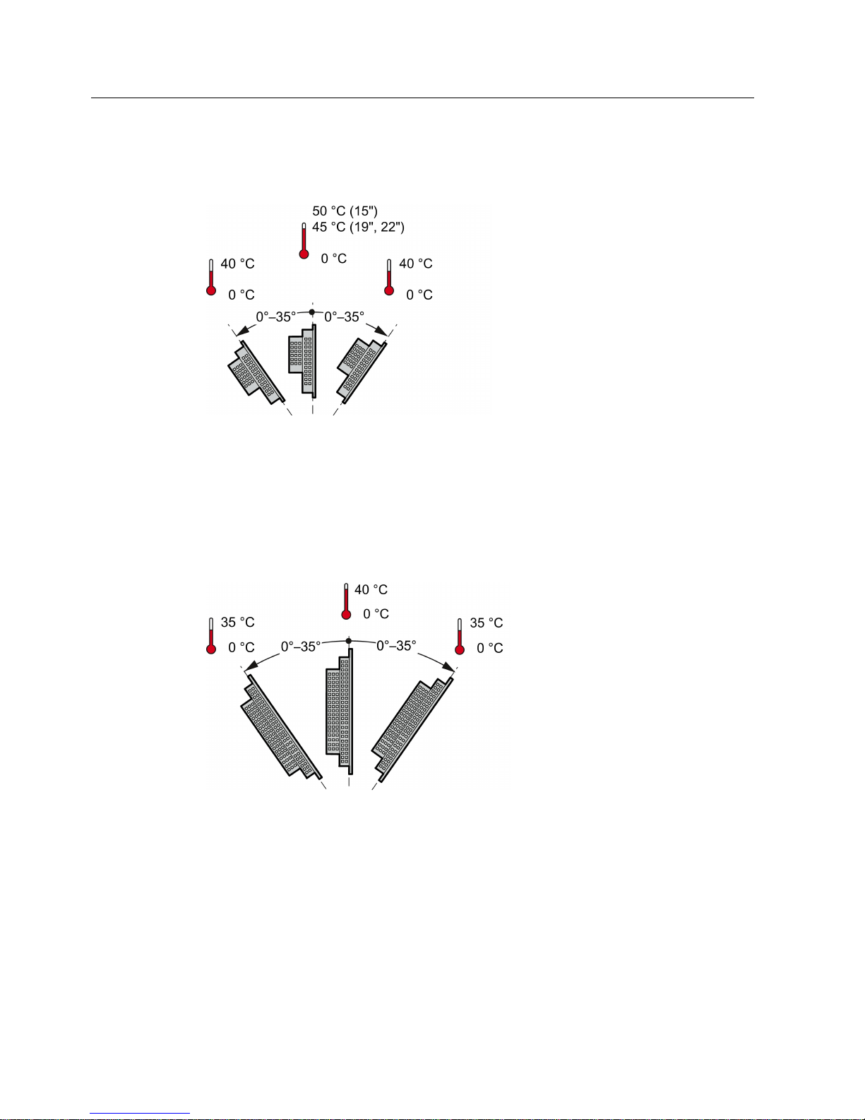
The device is self-ventilated and approved for inclined mounting at angles up to +/-35° in
stationary cabinets.
NOTICE
Damage due to overheating
Inclined installation reduces the convection by the device and therefore the maximum
permitted ambient temperature for operation.
If there is sufficient forced ventilation, the device can also be operated in the inclined
mounting position up to the maximum permitted ambient temperature for vertical
installation. The device may otherwise be damaged and its certifications and warranty will
be rendered null and void.
For information on permitted ambient temperatures, refer to the section Technical
specifications (Page 84).
Mounting position
Select one of the approved mounting positions for your device. The approved mounting
positions are described in the following sections.
Installing and connecting the device
3.1 Preparing for installation
Industrial Flat Panel IFP1500, IFP1900, IFP2200
28 Operating Instructions, 06/2014, A5E31298376-AB
Mounting in horizontal format
All devices are suitable for horizontal mounting positions.
A maximum ambient temperature of +50 °C is permitted for vertical mounting of the IFP1500
(0° tilt angle); a maximum of +40 °C is permitted for inclined mounting.
The ambient temperature for the IFP1900 and IFP2200 when installed vertically should not
exceed +45 °C.
Mounting in vertical format
All monitor and touch versions also support vertical mounting.
A maximum ambient temperature of +40 °C is permissible for vertical mounting (0° tilt angle);
a maximum of +35 °C is permitted for inclined mounting.
Installing and connecting the device
3.1 Preparing for installation
Industrial Flat Panel IFP1500, IFP1900, IFP2200
Operating Instructions, 06/2014, A5E31298376-AB
29
3.1.3
Checking clearances
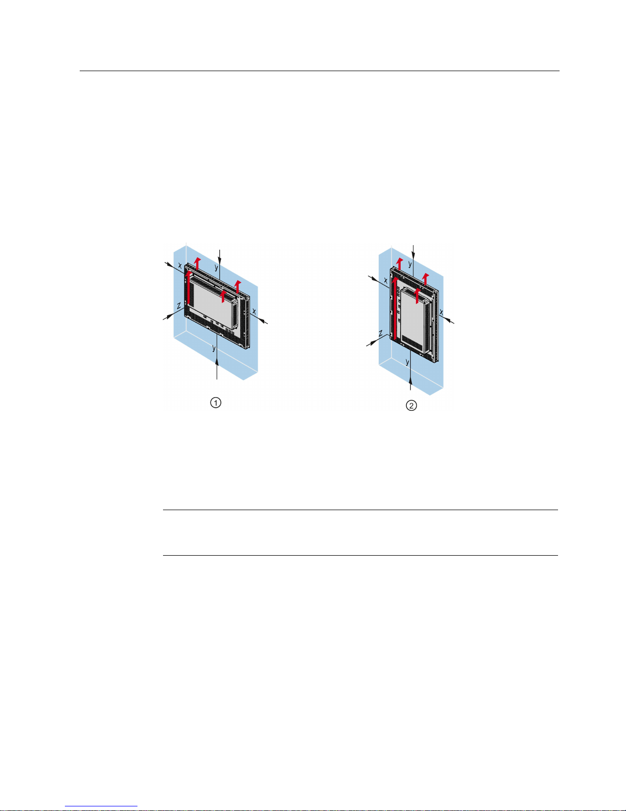
The following clearances are required around the device to ensure adequate self-ventilation:
● At least 15 mm to the right and left of the mounting cutout (in x direction) to allow for
insertion of the mounting clamps during installation
● At least 50 mm above and below the mounting cutout (in y direction) for ventilation
● At least 10 mm behind the rear panel of the device (in z direction)
The figure below shows the clearances required with horizontal and vertical installation of the
device:
①
Clearance for horizontal installation (all devices)
②
Clearance for vertical installation (monitor and touch versions only)
x
At least 15 mm distance
y
At least 50 mm distance
z
At least 10 mm distance
Note
Ensure that the maximum ambient temperature is not exceeded when mounting the device
in a cabinet and especially in a closed enclosure.
Installing and connecting the device
3.1 Preparing for installation
Industrial Flat Panel IFP1500, IFP1900, IFP2200
30 Operating Instructions, 06/2014, A5E31298376-AB
3.1.4
Preparing the mounting cutout
Note
Stability of the mounting cutout
The material in the area of the mounting cutout must be sturdy enough to ensure permanent
safe mounting of the device.
The force of the clamps or operation of the device may not lead to deform
ation of the
material in order to achieve the degrees of protection described below.
Degrees of protection
The various degrees of protection of the device can only be guaranteed if the following
requirements are met:
● To achieve the degree of protection specified in the technical specifications: Material
thickness at the mounting cut-out: 2 mm to 6 mm
● Permitted deviation from plane at the mounting cutout: ≤ 0.5 mm
This condition must also be met for the installed device.
● Permitted surface roughness in the area of the seal: ≤ 120 µm (R
z
120)
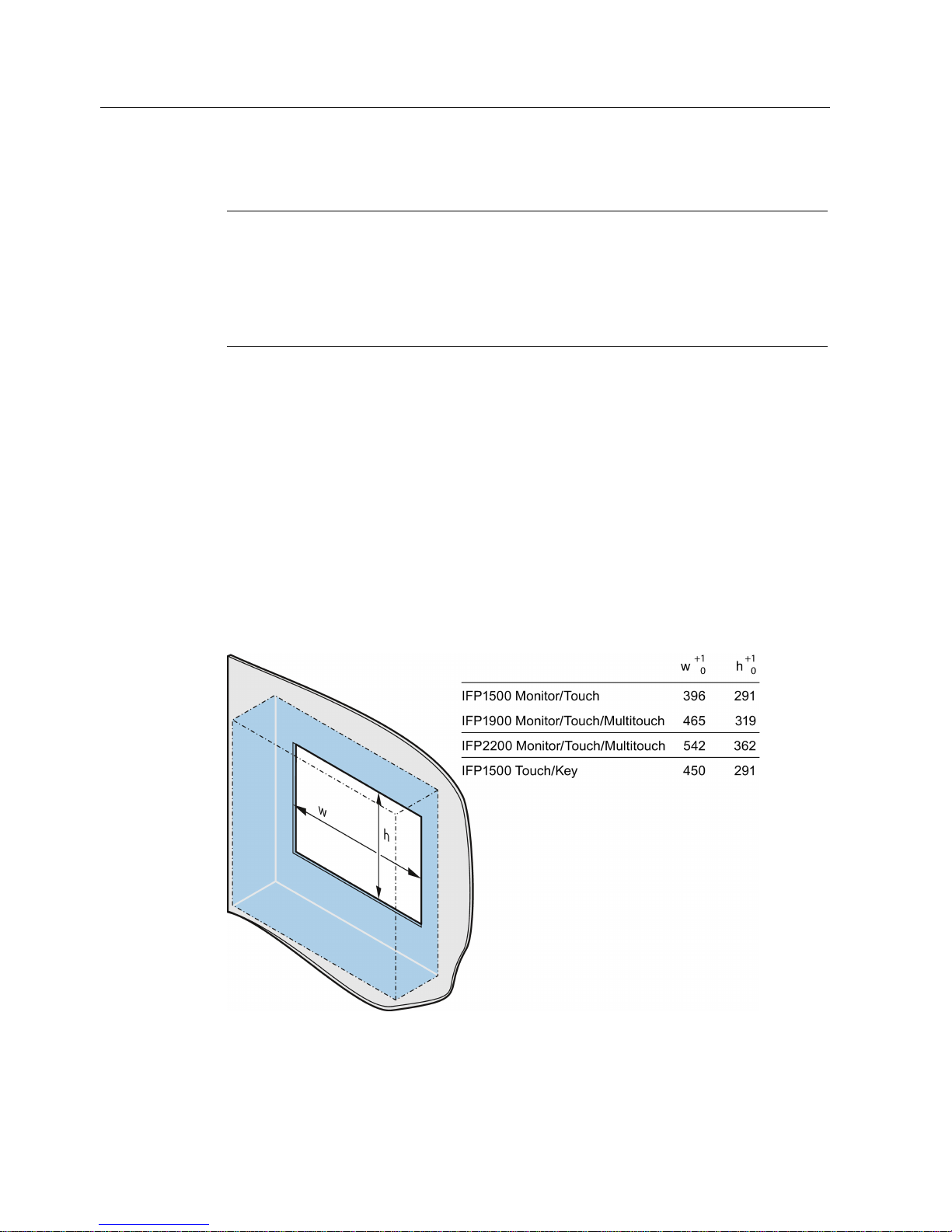
Dimensions of the mounting cutout
Width and height should be reversed accordingly when mounting in vertical format.
 Loading...