

Page 1

Preface, Contents
SIMATIC
IM 178-4
Manual
This manual is part of the product
with order number:
6ES7 178-4BH00-0AE0
Part 1: User Information
Product Overview
Installing and Removing the
Module
Wiring
Parameter Assignment
Preparing for Startup
Part 2: Reference Section
Functions of the IM 178-4
Diagnostics
1
2
3
4
5
6
7
Appendix
Technical Specifications
Configuration and
Parameter Assignment
Frame for the IM 178-4
Glossary, Index
A
B
Page 2

Safety Guidelines
This manual contains notices which you should observe to ensure your own personal safety, as well as to
protect the product and connected equipment. These notices are highlighted in the manual by a warning
triangle and are marked as follows according to the level of danger:
Danger
!
indicates that death, severe personal injury or substantial property damage will result if proper
precautions are not taken.
Warning
!
indicates that death, severe personal injury or substantial property damage can result if proper precautions are not taken.
Caution
!
indicates that minor personal injury or property damage can result if proper precautions are not taken.
Note
draws your attention to particularly important information on the product, handling the product, or to a
particular part of the documentation.
Qualified Personnel
Only qualified personnel should be allowed to install and work on this equipment. Qualified persons are
defined as persons who are authorized to commission, to ground, and to tag circuits, equipment, and
systems in accordance with established safety practices and standards.
Correct Usage
Note the following:
Warning
!
Trademarks
This device may only be used for the applications described in the catalog or the technical description,
and only in connection with devices or components from other manufacturers which have been approved
or recommended by Siemens.
This product can only function correctly and safely if it is transported, stored, set up, and installed
correctly , and operated and maintained as recommended.
SIMA TICR, SIMA TIC HMIR and SIMA TIC NETR are registered trademarks of SIEMENS AG.
Third parties using for their own purposes any other names in this document which refer to trademarks
might infringe upon the rights of the trademark owners.
Disclaimer of LiabilityCopyright E Siemens AG 1998 All rights reserved
The reproduction, transmission or use of this document or its contents is not
permitted without express written authority. Offenders will be liable for
damages. All rights, including rights created by patent grant or registration of
a utility model or design, are reserved.
Siemens AG
Bereich Automatisierungs- und Antriebstechnik
Geschaeftsgebiet Industrie Automatisierungssystem
Postfach 4848, D- 90327 Nuernberg
Index-2
Siemens Aktiengesellschaft C79000-G7076-C178
We have checked the contents of this manual for agreement with the
hardware and software described. Since deviations cannot be precluded
entirely, we cannot guarantee full agreement. However, the data in this
manual are reviewed regularly and any necessary corrections included in
subsequent editions. Suggestions for improvement are welcomed.
E Siemens AG 1998
Subject to change without prior notice.
C79000-G7076-C178-01
IM 178-4
Page 3

Preface
Purpose of the Documentation
This manual describes all the steps necessary to use the function module
IM 178-4. It will help you to become familiar with the functions of the IM 178-4
quickly and effectively.
Content of the Manual
This manual describes the hardware and software of the IM 178-4. It deals with the
following topics:
S Product overview
S Installation and removal of the module
S Wiring
S Parameter assignment
S Starting up
S Functions
S Diagnostics
S Appendix
Audience
The manual is intended for the following audience:
S Fitters
S Programmers
S Commissioning engineers
S Service and maintenance personnel
Applicability of the Manual
This manual contains the description of the function module IM 178-4 valid at the
time of publication. We reserve the right to describe modifications in the
functionality of the IM 178-4 in a Product Information leaflet.
IM 178-4
C79000-G7076-C178-01
iii
Page 4

Preface
Finding Your Way in the Manual
To help you find specific information quickly, the manual includes the following :
S At the start of the manual, you will find a complete table of contents.
S In the Appendix, you will find a glossary in which the most important
terminology used in the manual is explained.
S At the end of the manual, you will find a comprehensive index with which you
can locate topics and specific information quickly.
Other Literature Required
To understand this manual, you should also be familiar with the manual
Distributed I/O System
Standards
The S7-300 programmable controller complies with the standard IEC 1131.
Recycling and Disposal
The SIMATIC S7-300 is an environmentally friendly product!
The SIMATIC S7-300 has the following environmental features:
S Plastic casing highly fireproof despite halogen–free flame protection
S Labeled by laser (in other words no unnecessary labels)
S Plastic materials indicated in compliance with DIN 54840
S Less material used due to small dimensions, less components due to
integration in ASICs
The SIMATIC S7-300 is suitable for recycling due to its low pollutant content .
For environmentally friendly recycling and disposal of your old SIMATIC PLC using
the most modern methods, contact:
ET 200
.
Siemens Aktiengesellschaft
Anlagenbau und Technische Dienstleistungen
ATD TD 3 Kreislaufwirtschaft
Postfach 32 40
D-91050 Erlangen
Germany
Phone: ++49 / 91 31 / 73 36 98
Telefax: ++ 49 / 91 31 / 72 66 43
This Siemens department offers individual counseling and a comprehensive and
flexible disposal system at a fixed price. Following disposal, you receive a
breakdown of the materials and a certification of the materials.
iv
C79000-G7076-C178-01
IM 178-4
Page 5

CD-ROM
You can also order the entire SIMATIC S7 documentation on a CD-ROM.
Further Support
If you have questions about using the product described in the manual and cannot
find the answer here, please contact your local Siemens representative. You will
find the addresses in the appendix ”SIEMENS Worldwide” in the
Programmable Controller, Hardware and Installation, CPU Data”
If you have questions or comments about the manual itself, please complete the
reply card at the end of the manual and send it to address shown. Please take a
few minutes to give your own personal assessment of the manual on the reply
card.
To familiarize users with the SIMATIC automation systems, we offer a variety of
training courses. If you are interested in these courses, please contact your
Regional Training Center or the Central Training Center in D-90327 Nürnberg,
Germany, Tel. ++49/911/895 3154.
Preface
”S7-300, M7-300
manual
.
The Latest Information
You can always obtain the very latest information about SIMATIC products from
the following sources:
S On the Internet: http://www.aut.siemens.de/
S By calling fax polling no. 08765-93 00 5000
Our SIMATIC Customer Support also supports you with up-to-date information and
downloads, that you may find helpful when using SIMATIC products:
S On the Internet: http://www.aut.siemens.de/simatic–cs
S In the SIMATIC Customer Support Mailbox: number
+49 (911) 895-7100
If you connect to the mailbox, use a modem with up to V.34
(28.8 Kbauds), with the following parameter settings:
8, N, 1, ANSI, or dial on ISDN (x.75, 64 Kbps).
SIMATIC Customer Support is available at the following phone and fax numbers or
e–mail addresses. You can also send enquiries by mail on the Internet or by mail to
the mailbox number above.
IM 178-4
C79000-G7076-C178-01
v
Page 6

Preface
Nuremberg
Johnson City
Singapore
Simatic Basic Hotline
Nuremberg
SIMA TIC BASIC Hotline
Local time: Mo.-Fr . 8:00
to 18:00
Phone: +49 (911) 895-7000
Fax: +49 (911) 895-7002
E-mail: simatic.support@
nbgm.siemens.de
SIMA TIC Premium Hotline
(charged, only with
SIMA TIC Card)
Time: Mo.-Fr . 0:00 to 24:00
Phone: +49 (911) 895-7777
Fax: +49 (911) 895-7001
Johnson City
SIMA TIC BASIC Hotline
Local time: Mo.-Fr . 8:00
to 17:00
Phone: +1 423 461-2522
Fax: +1 423 461-2231
E-mail: simatic.hotline@
sea.siemens.com
Singapore
SIMA TIC BASIC Hotline
Local time: Mo.-Fr . 8:30
to 17:30
Phone: +65 740-7000
Fax: +65 740-7001
E-mail: simatic@
singnet.com.sg
vi
C79000-G7076-C178-01
IM 178-4
Page 7

Contents
1 Product Overview 1-1. . . . . . . . . . . . . . . . . . . . . . . . . . . . . . . . . . . . . . . . . . . . . . . . . . . . . .
1.1 What Can the IM 178-4 Do? 1-2. . . . . . . . . . . . . . . . . . . . . . . . . . . . . . . . . . . . . .
1.2 Fields of Application of the IM 178-4 1-2. . . . . . . . . . . . . . . . . . . . . . . . . . . . . . .
1.3 The Hardware of the IM 178-4 1-3. . . . . . . . . . . . . . . . . . . . . . . . . . . . . . . . . . . .
2 Installing and Removing the Module 2-1. . . . . . . . . . . . . . . . . . . . . . . . . . . . . . . . . . . . .
3 Wiring 3-1. . . . . . . . . . . . . . . . . . . . . . . . . . . . . . . . . . . . . . . . . . . . . . . . . . . . . . . . . . . . . . . . .
3.1 Pinout of the Front Connector 3-1. . . . . . . . . . . . . . . . . . . . . . . . . . . . . . . . . . . . .
3.2 Description of the Individual Pins (Notes, Explanations) 3-4. . . . . . . . . . . . . . .
3.3 Wiring the Front Connector 3-6. . . . . . . . . . . . . . . . . . . . . . . . . . . . . . . . . . . . . . .
3.4 Wiring and Connecting the Bus Connector 3-8. . . . . . . . . . . . . . . . . . . . . . . . . .
4 Parameter Assignment 4-1. . . . . . . . . . . . . . . . . . . . . . . . . . . . . . . . . . . . . . . . . . . . . . . . . .
4.1 Methods of Assigning Parameters to the IM 178-4 4-1. . . . . . . . . . . . . . . . . . .
4.2 GSx File 4-3. . . . . . . . . . . . . . . . . . . . . . . . . . . . . . . . . . . . . . . . . . . . . . . . . . . . . . .
5 Preparing for Startup 5-1. . . . . . . . . . . . . . . . . . . . . . . . . . . . . . . . . . . . . . . . . . . . . . . . . . .
5.1 Setting the PROFIBUS Address of the IM 178-4 5-1. . . . . . . . . . . . . . . . . . . . .
5.2 Checklist of the Mechanical Construction 5-3. . . . . . . . . . . . . . . . . . . . . . . . . . .
5.3 Checklist for Configuration/Parameter Assignment 5-3. . . . . . . . . . . . . . . . . . .
6 Functions of the IM 178-4 6-1. . . . . . . . . . . . . . . . . . . . . . . . . . . . . . . . . . . . . . . . . . . . . . .
6.1 Description of the Functions 6-1. . . . . . . . . . . . . . . . . . . . . . . . . . . . . . . . . . . . . .
6.1.1 Cyclic Processing 6-1. . . . . . . . . . . . . . . . . . . . . . . . . . . . . . . . . . . . . . . . . . . . . . .
6.1.2 Error Monitoring 6-5. . . . . . . . . . . . . . . . . . . . . . . . . . . . . . . . . . . . . . . . . . . . . . . . .
6.2 User Data Interface 6-8. . . . . . . . . . . . . . . . . . . . . . . . . . . . . . . . . . . . . . . . . . . . . .
7 Diagnostics 7-1. . . . . . . . . . . . . . . . . . . . . . . . . . . . . . . . . . . . . . . . . . . . . . . . . . . . . . . . . . . .
7.1 Status and Diagnostic LEDs 7-1. . . . . . . . . . . . . . . . . . . . . . . . . . . . . . . . . . . . . .
7.2 Diagnostic Data of the IM 178-4 7-3. . . . . . . . . . . . . . . . . . . . . . . . . . . . . . . . . . .
7.2.1 Structure of Slave Diagnostics 7-3. . . . . . . . . . . . . . . . . . . . . . . . . . . . . . . . . . . .
7.2.2 Structure of the First 6 Bytes of the Slave Diagnostic Data 7-4. . . . . . . . . . . .
7.2.3 Structure of the ID-Related and Device-Related Slave Diagnostic Data 7-6.
IM 178-4
C79000-G7076-C178-01
vii
Page 8

Contents
A Technical Specifications A-1. . . . . . . . . . . . . . . . . . . . . . . . . . . . . . . . . . . . . . . . . . . . . . . .
A.1 Technical Data of the IM 178-4 A-4. . . . . . . . . . . . . . . . . . . . . . . . . . . . . . . . . . . .
B Configuration and Parameter Assignment Frame for the IM 178-4 B-1. . . . . . . . . .
B.1 Structure of the Configuration Frame B-1. . . . . . . . . . . . . . . . . . . . . . . . . . . . . . .
B.2 Structure of the Parameter Assignment Frame B-2. . . . . . . . . . . . . . . . . . . . . .
B.2.1 Standard Section of the Parameter Assignment Frame B-2. . . . . . . . . . . . . . .
B.2.2 Parameters for the DP Attachment B-3. . . . . . . . . . . . . . . . . . . . . . . . . . . . . . . .
B.2.3 Technological Parameters B-4. . . . . . . . . . . . . . . . . . . . . . . . . . . . . . . . . . . . . . . .
Glossary Glossary-1. . . . . . . . . . . . . . . . . . . . . . . . . . . . . . . . . . . . . . . . . . . . . . . . . . . . . . . . . .
Index Index-1. . . . . . . . . . . . . . . . . . . . . . . . . . . . . . . . . . . . . . . . . . . . . . . . . . . . . . . . . . . . . . . .
viii
C79000-G7076-C178-01
IM 178-4
Page 9

Product Overview
Order Number
The product has the order number: 6ES7 178-4BH00-0AE0
Components of the product
1 Module
1 CD ROM with the following content:
S the readme.wri, liesmich.wri, lisezmoi.wri, leggimi.wri and leame.wri files
S the Englisch, German, French and Italian manual for the IM 178-4
(IM178_E.PDF, IM178_D.PDF, IM178-4_F.PDF, IM178-4_I.PDF)
S Device database:
– German: SIEM8064.GSG
– English: SIEM8064.GSE
– French: SIEM8064.GSF
1
– Italian: SIEM8064.GSI
S the bitmap files IM178__N.BMP and IM178__S.BMP
S Acrobat Reader
IM 178-4
C79000-G7076-C178-01
1-1
Page 10

Product Overview
1.1 What Can the IM 178-4 Do?
What Can the IM 178-4 Do?
The IM 178-4 is a DP slave with a fixed number of I/Os and has the same design
as S7-300 modules. It has two technologically identical but independent channels
for position detection of incremental position encoders and/or SSI position
encoders and for controlling analog drives ("10 V). The module is attached to the
DP network via a 9 pin sub-D male connector.
Per channel, the module has the following:
S One input for position detection with SSI position encoders or incremental
encoders with 5 V differential signals
S One analog output "10 V
S 3 digital inputs (2 with fixed functions)
S 3 digital outputs that you can use as required.
1.2 Fields of Application of the IM 178-4
Where can you use the IM 178-4?
The IM 178-4 is required mainly by users who want to create distributed position
detection and positioning systems in conjunction with conventional drives with an
analog interface ("10 V) and conventional displacement measuring systems (SSI,
incremental position encoders with 5V differential signals). The technological
functionality is no longer in the individual positioning modules as previously but in a
powerful centralized controller.
1-2
C79000-G7076-C178-01
IM 178-4
Page 11
1.3 The Hardware of the IM 178-4
Module Overview
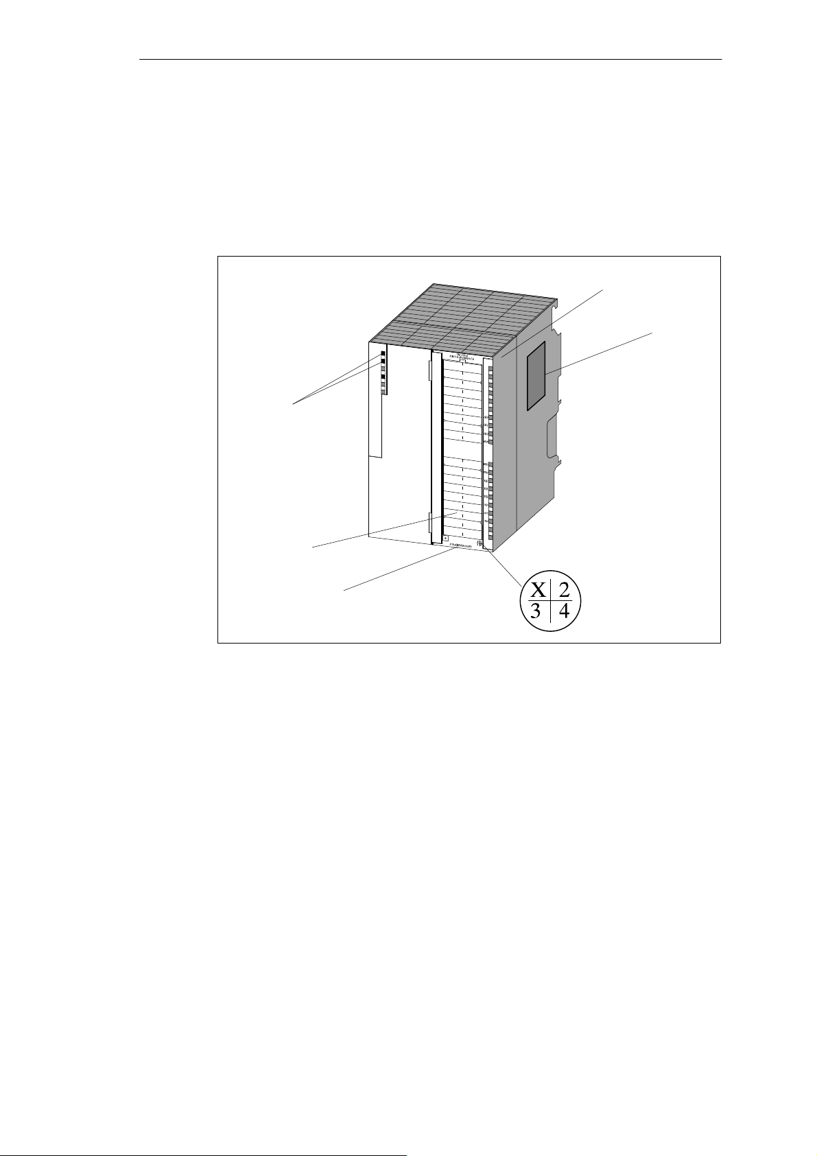
The following diagram shows the IM 178-4 module with its front connector.
Diagnostic LEDs
Product Overview
Front Connector
Type Label
Labeling Strip
Figure 1-1 The IM 178-4 Module
Front Connector
With the IM 178-4, the following attachments are possible via the front connector:
S 2 inputs for position detection with SSI position encoders or incremental
position encoders with 5 V differential signals
S 6 digital inputs
S 6 digital outputs
S 2 analog outputs "10 V
S Power supply 1L+
S Load voltage 2L+
The front connector must be ordered separately (order number
6ES7 392-1AM00-0AA0
Order Number
Version
IM 178-4
C79000-G7076-C178-01
1-3
Page 12

Product Overview
Labeling Strip
The module has a labeling strip on the right front panel that you can label with your
signal names.
The inner side of the right front panel has the pinout of the IM 178-4.
Order Number and Version
The order number and version are shown at the bottom of the front panel.
Status and Diagnostics LEDs
Labeling Color Function
SF red Group error (technology)
BF red Bus error
ON green Operating display
0I0 green Digital input 0 of channel 0
0I1 green Digital input 1 of channel 0
0I2 green Digital input 2 of channel 0
0Q0 green Digital output 0 of channel 0
0Q1 green Digital output 1 of channel 0
0Q2 green Digital output 2 of channel 0
1I0 green Digital input 0 of channel 1
1I1 green Digital input 1 of channel 1
1I2 green Digital input 2 of channel 1
1Q0 green Digital output 0 of channel 1
1Q1 green Digital output 1 of channel 1
1Q2 green Digital output 2 of channel 1
1-4
C79000-G7076-C178-01
IM 178-4
Page 13

Installing and Removing the Module
Selecting the Location
A horizontal installation is preferable. If you install the module vertically, remember
that the ambient temperature is restricted (max. 40 _C).
Important Safety Rules
For modules in the S7-300 design, there are important rules that must be kept to.
These rules and regulations are explained in the manual
Controller, Hardware and Installation, CPU Data
Rules
When installing the IM 178-4, no particular measures are necessary regarding
electrostatic discharge (ESD).
Required Tools
.
2
S7-300 Programmable
Installation
To install or remove the IM 178-4, you require a 4.5 mm screwdriver.
To install the IM 178-4 on a rail, follow the steps outlined below. For further
information about installing modules, refer to the manual
Controller, Hardware and Installation, CPU Data
1. Hook the IM 178-4 on to the rail and push in the bottom section of the module.
2. Screw the IM 178-4 tight (torque approximately 0.8 to 1.1 Nm).
3. Plug in the front connector and screw it tight.
4. Fit the shield contact element.
The order number of the shield contact element is 6ES7 390-5AA00-0AA0.
5. Plug in the bus connector.
The order number of the bus connector is 6ES7 972-0BA10-0XA0 or
6ES7 972-0BB10-0XA0.
.
S7-300 Programmable
IM 178-4
C79000-G7076-C178-01
2-1
Page 14

Installing and Removing the Module
Removing/Replacing the Module
To remove the IM 178-4, follow the steps outlined below. For further information
about removing modules, refer to the manual
Hardware and Installation, CPU Data
1. Turn off the auxiliary voltage and the load voltage at the front connector.
2. Open the front panel. If you require it, remove the label from inside the panel.
3. Release the mounting screw on the front connector and remove the connector.
4. Unplug the bus connector.
Note
If the LAN cable is connected through, you can remove the bus connector from the
DP interface without interrupting the data exchange on the bus.
5. Release the mounting screw on the module.
S7-300 Programmable Controller,
6. Pull out the bottom of the module from the rail and remove it upwards.
7. If required, install the new module.
2-2
C79000-G7076-C178-01
IM 178-4
Page 15
Wiring
3.1 Pinout of the Front Connector
Front connector
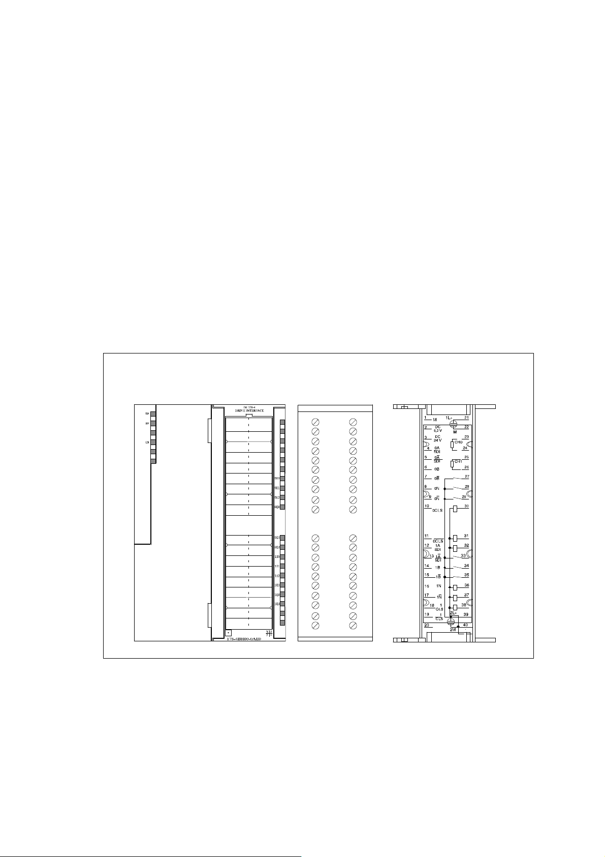
You connect the position encoders, the analog outputs, the digital inputs and
outputs, the sensor power supply and the module voltage via the 40-pin front
connector.
Figure 3-1 shows the front of the module, the front connector and the inner side of
the front panel with the pinout plan.
3
Front connectorFront view of the module Inside the front panel
Figure 3-1 Front Connector of the IM 178-4
1
2
3
4
5
6
7
8
9
0
1
1
1
2
1
3
1
4
1
5
1
6
1
7
1
8
1
9
1
0
2
1
2
2
2
2
3
4
2
5
2
6
2
7
2
2
8
2
9
0
3
3
1
3
2
3
3
3
4
3
5
3
6
3
7
3
8
3
9
4
0
3
IM 178-4
C79000-G7076-C178-01
3-1
Page 16

Wiring
Pinout of the Front Connector
Table 3-1 Pinout of the Front Connector
Pin
1 M OUT – Sensor power supply ground
2 5.2 V DC OUT – 5 V sensor power supply
3 24 V DC OUT – 24 V sensor power supply
4 0A/SDI IN – Channel 0 count signal A / serial data input
5 0A/SDI IN – Channel 0 count signal A / serial data input, inverted
6 0B IN – Channel 0 count signal B
7 0B IN – Channel 0 count signal B, inverted
8 0N IN – Channel 0 zero mark
9 0N IN – Channel 0 zero mark, inverted
10 0CLS OUT – Channel 0 shift clock CLS
11 0CLS OUT – Channel 0 shift clock CLS, inverted
12 1A/SDI IN – Channel 1 count signal A / serial data input
13 1A/SDI IN – Channel 1 count signal A / serial data input, inverted
14 1B IN – Channel 1 count signal B
15 1B IN – Channel 1 count signal B inverted
16 1N IN – Channel 1 zero mark
17 1N IN – Channel 1 zero mark, inverted
18 1CLS OUT – Channel 1 shift clock CLS
19 1CLS OUT – Channel 1 shift clock CLS, inverted
20 –
21 1L+ IN – Auxiliary voltage 1L+
22 M IN – Auxiliary voltage ground
23 0AO OUT – Analog output 0AO
24 0BS OUT – Reference signal 0BS
25 1AO OUT – Analog output 1AO
26 1BS OUT – Reference signal 1BS
27 0I0 IN green Digital input 0I0
28 0I1 IN green Digital input 0I1
29 0I2 IN green Digital input 0I2
30 0Q0 OUT green Digital output 0Q0
31 0Q1 OUT green Digital output 0Q1
32 0Q2 OUT green Digital output 0Q2
33 1I0 IN green Digital input 1I0
Name Input/
Output
LED Function
3-2
C79000-G7076-C178-01
IM 178-4
Page 17

Table 3-1 Pinout of the Front Connector
Wiring
Pin FunctionLEDInput/
34 1I1 IN green Digital input 1I1
35 1I2 IN green Digital input 1I2
36 1Q0 OUT green Digital output 1Q0
37 1Q1 OUT green Digital output 1Q1
38 1Q2 OUT green Digital output 1Q2
39 2L+ IN – Load voltage 2L+
40 2M IN – Load voltage ground
Name
Output
Note
If you supply the sensor with an external voltage, connect the ground of the
external voltage to the ground of the module (terminal 1 or 22).
IM 178-4
C79000-G7076-C178-01
3-3
Page 18

Wiring
3.2 Description of the Individual Pins (Notes, Explanations)
24 V Power Supply
For the power supplies of the IM 178-4, connect a DC voltage of 24 V to pins 1L+
and M and 2L+ and 2M.
Caution
!
Make sure that the polarity of the 24 V power supply is correct otherwise the
module will be damaged.
The 24 V power supply must meet the following requirements:
Only an extra-low DC voltage of ≤ 60 V that is safely isolated from the main power
supply must be used as the 24 V power supply. Safe isolation of the power supply
can be achieved by adhering to the requirements of VDE 0100 Part 410 / HD
384-4-41 / IEC 364-4-41 (as functional extra-low voltage with safe isolation) or
VDE 0805 / EN 60950 / IEC 950 (as safety extra-low voltage SELV) or VDE 0106
Part 101.
5.2 V and 24 V Sensor Power Supplies
From the 24 V power supply 1L+/M, the module generates a voltage of 5.2 V. This
voltage is applied to DC5.2V (pin 2) as a short-circuit proof power supply for the
sensors and can accept a maximum load of 600 mA. The ground of the sensor
power supply is connected to M (Pin 1).
For sensors that require a power supply of 24 V, the short-circuit protected
auxiliary voltage is available at DC24V (Pin 3).
Note
A short-circuit of the 5.2 V sensor power supplies leads to a failure of the module.
Sensor Pins
Per channel, you can connect two different sensor types using shielded cables, as
follows:
S Incremental sensors complying with RS 422:
The signals A, A, B, B and N, N are connected via the correspondingly labeled
pins.
3-4
S SSI position encoders:
The signals SDI, SDI and CLS, CLS are connected to the correspondingly
labeled pins.
C79000-G7076-C178-01
IM 178-4
Page 19

Digital Inputs I0 to I2
Per channel, the IM 178-4 has three digital inputs. These are operated with a rated
voltage of 24 V.
The digital inputs are electrically isolated from the DP interface and the sensor
signals.
The digital inputs I0 and I1 have fixed functions depending on the parameter
assignment (see Chapter 6). Pin I0 must be connected using a shielded cable.
Digital Outputs Q0 to Q2
Per channel, the IM 178-4 has three digital outputs. These are supplied from the
24 V power supply 2L+.
The digital outputs are electrically isolated from the DP interface and the sensor
signals.
The digital outputs are current–sourcing switches and can accept a load current of
0.5 A. They are protected against overload and short–circuits.
Wiring
Note
The direct connection of relays and contactors is possible without external
protective circuits.
Analog Outputs
Per channel, the IM 178-4 has one analog output of ±10 V with a resolution of ±13
bits.
The analog outputs must be connected using shielded cables.
Note
Turning on the auxiliary voltage 1L+ can lead to the analog outputs supplying a
spurious pulse for several ms. This spurious pulse must not cause the power
circuits to be activated. This must be avoided by appropriate external wiring of the
module (digital output to enable the power circuits).
IM 178-4
C79000-G7076-C178-01
3-5
Page 20

Wiring
3.3 Wiring the Front Connector
Cables
When selecting suitable cables, follow the rules outlined below:
S The cables for digital inputs 0I0 and 1I0 must be shielded.
S The cables for the position encoder signals must be shielded; the pairs of cores
must be twisted.
S The shields of the cables for the count signals must be connected to ground
both at the position encoder and in the immediate vicinity of the module, for
example using the shield contact element.
S Use flexible cables with cross–sections of 0.25 to 1.5 mm2.
S The cables for the analog outputs must be shielded.
Note
If the sensor is supplied with power from the module, the conductor cross-section
must be large enough so that the required voltage is applied to the sensor despite
the voltage drop along the cable.
S A wire-end ferrule is not required. If you use wire-end ferrules, use only those
without an insulation collar according to DIN 46228 form A, short version!
Tools Required
A 3.5 mm screwdriver.
3-6
C79000-G7076-C178-01
IM 178-4
Page 21

Wiring Procedure
When wiring the front connector, follow the steps outlined below:
Warning
!
Risk of personal injury.
If you wire the front connector of the IM 178-4 with the power supply on, you may
be injured by the electrical current.
Make sure that you wire the IM 178-4 only when the power supply is turned off.
1. Open the front panel and bring the front connector into a position so that you
can wire it.
2. Strip the insulation from the wires (remove 6 mm of the insulation).
3. Are you using wire–end ferrules?
If yes: Crimp the wire-end ferrules onto the wires.
Wiring
4. Thread the accompanying strain relief into the front connector.
5. If the wires are led out towards the bottom, start wiring from the bottom,
otherwise from the top. You should also screw down terminals that are not in
use (tightening torque 0.6 to 0.8 Nm).
6. Pull the strain relief for the cables tight.
7. Screw the front connector into the operating position.
8. Establish contact between the shields of the cables on the shield contact
element or on the shield contact rail.
9. Enter the terminal assignments on the pinout plan.
Figure 3-2 shows the IM 178-4 with shielded cables and a shield contact element.
IM 178-4
C79000-G7076-C178-01
3-7
Page 22
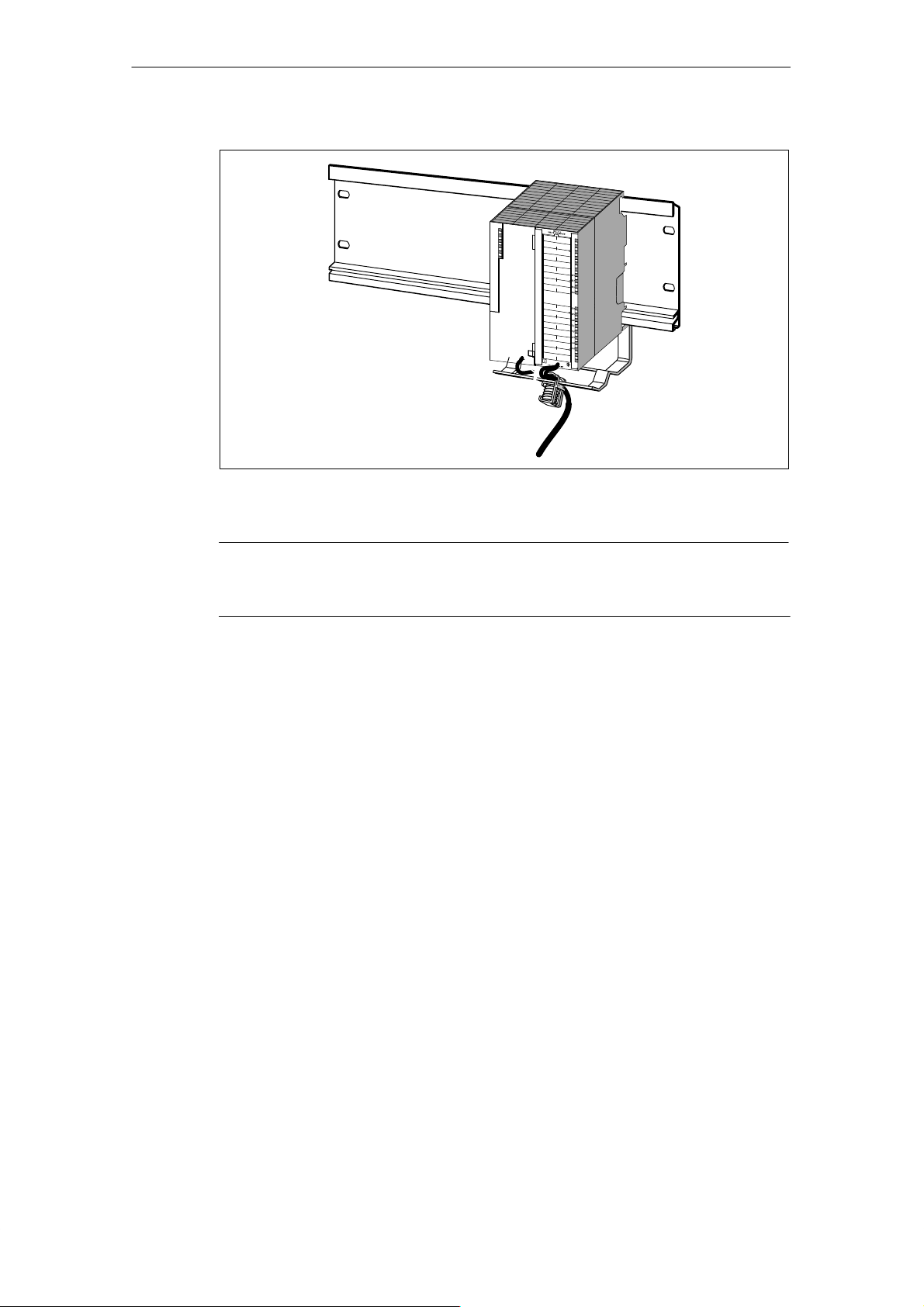
Wiring
Figure 3-2 Connecting Shielded Cables to the IM 178-4
Note
For a detailed description of wiring the front connector, refer to the manual
Programmable Controller, Hardware and Installation, CPU Data
3.4 Wiring and Connecting the Bus Connector
LAN Cable
As the LAN cable, use the PROFIBUS shielded twisted pair cable or fiber-optic
cable. For ordering information, refer to the Catalog
Cable Lengths
For information about the length of the LAN cable in a segment and about
interconnecting segments, refer to the manuals describing the DP master.
The cable lengths specified in these manuals are only guaranteed for the
PROFIBUS cable (see Catalog
ST 70
).
ST 70
S7-300
.
.
3-8
C79000-G7076-C178-01
IM 178-4
Page 23
Attaching the LAN Cable
Connect the LAN cable to the bus connector with order numbers
6ES7 972-0BA10-0XA0 or 6ES7 972-0BB10-0XA0 ... as follows:
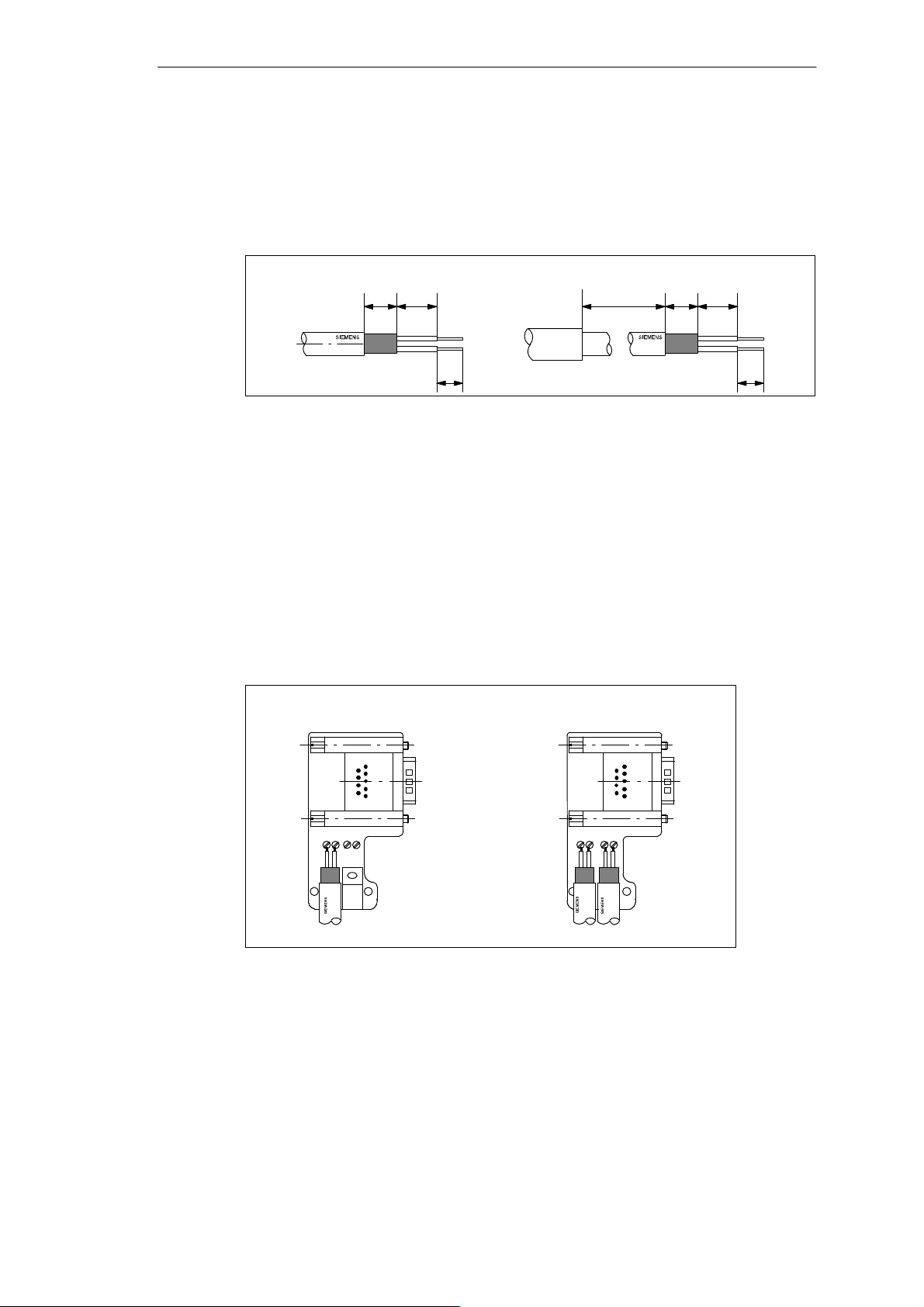
1. Strip the insulation from the LAN cable as shown in Figure 3-3.
6XV1 830–0AH10/-3BH10 6XV1 830–3AH10
Wiring
7,5 9
6
Figure 3-3 Lengths for Stripping Insulation for the Bus Connector (6ES7 972-0B?0-0XA0)
120
7,5 9
6
2. Open the casing of the bus connector by undoing the casing screws and
removing the cover.
3. Fit the green and red wire in to the screw terminal block as shown in Figure 3-4.
Make sure that you always connect the same wire to the same terminal A or B
(for example terminal A is always wired with the green wire and terminal B
always with the red wire).
4. Press the cable jacket between the two clamping posts. This fixes the cable in
place.
5. Screw the green and red wire into the terminal block.
LAN cable connection for first and
last node in the segment
1
LAN cable connection for all
other nodes in the segment
1
: The LAN cable can be connected to the right or left terminals!
Figure 3-4 Connecting the LAN Cable to the Bus Connector (6ES7 972-0B?10 0XA0)
6. Screw the casing back together.
Make sure that the cable shield makes contact with the shield clamp.
IM 178-4
C79000-G7076-C178-01
A B A B A B A B
3-9
Page 24
Wiring
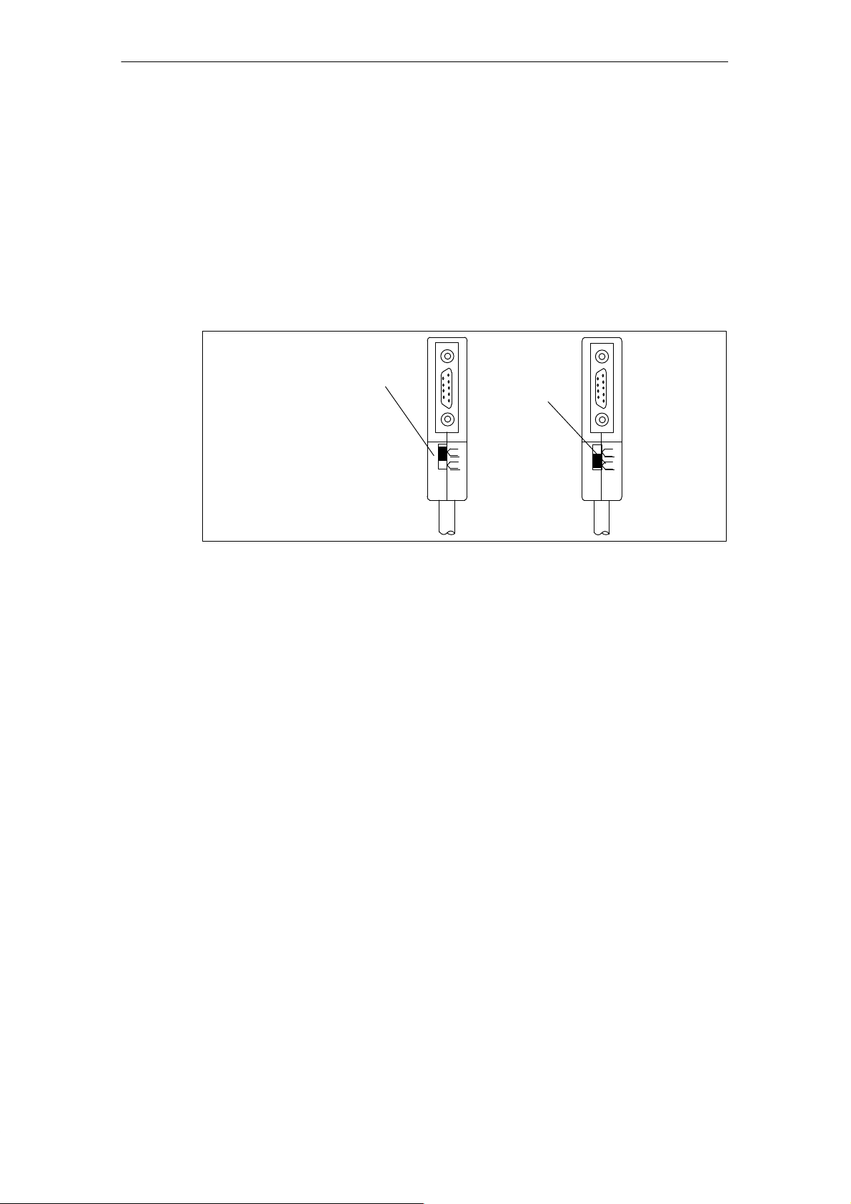
Connecting the Bus Connector
To connect the bus connector, follow the steps outlined below:
1. Plug the bus connector on to the IM 178-4.
2. Secure the bus connector on the IM 178-4 with the screws.
3. If the bus connector is at the start or end of a segment, the terminating resistor
must be activated (switch setting ”ON”) (see Figure 3-5).
Make sure that the nodes on which the terminating resistor is activated are always
supplied with voltage during startup and operation.
Terminating
resistor
activated
on
off
Terminating
resistor not
activated
on
off
Figure 3-5 Bus connector (6ES7 972-0B?10-0XA0): Terminating resistor activated and
deactivated
3-10
C79000-G7076-C178-01
IM 178-4
Page 25

Parameter Assignment
4.1 Methods of Assigning Parameters to the IM 178-4
Requirements for Assigning Parameters with Hardware Configuration
To use Hardware Configuration when assigning parameters to the IM 178-4, make
the following preparations:
1. Copy the file SIEM8064.gse to the STEP 7 directory S7DATA\GSD, for
example using the menu command Options"Install New DDB ...
2. Copy the files im178__n.bmp and im178__s.bmp to the STEP 7 directory
S7DATA\NSBMP.
3. Update the local module catalog (in STEP 7 V4.02 with the menu command
Options"Update Catalog).
You will then find the IM 178-4 in the hardware catalog under Other FIELD
DEVICES\OTHER.
4
Requirements for Parameter Assignment With COM PROFIBUS
Before you can use COM PROFIBUS to assign parameters to the IM 178-4, you
must make the following preparations:
1. Copy the files SIEM8064.gsd, SIEM8064.gse, SIEM8064.gsf and
SIEM8064.gsi to the PROFIBUS GSD folder.
2. Copy the files im178__n.bmp and im178__s.bmp to the COM PROFIBUS
Bitmaps folder.
3. Update the local module catalog (menu command File"Scan GSD Files).
The station type IM 178-4 is then available in the slave family “Other”.
IM 178-4
C79000-G7076-C178-01
4-1
Page 26

Parameter Assignment
Note
In slot 4, configure one of the proposed technology slots:
S Q4 words / I12 words:
Word consistency in the Q and I areas
S Q4 words / I12 words consistent (standard situation):
Word consistency in the Q area, consistency over the entire I area
If you only require the less significant 16 bits of the actual position value, you can
also select “Q4 words / I12 words” .
Requirements for Parameter Assignment with a Parameter Assignment Frame
To assign parameters to the IM 178-4 using a parameter assignment frame, you
must know how the configuration and parameter assignment frames are
structured. This is explained in Appendix C.
Parameter Assignment
Each DP standard slave receives its parameters from the DP master when it starts
up itself or when the master is started.
Successful parameter assignment is indicated by the value TRUE in the PARA
status bit for each channel. A parameter assignment error is indicated by FALSE in
the PARA status bit and an entry in the slave diagnostic data if this is enabled.
The diagnostic LED remains lit until both channels have been assigned error-free
parameters.
Until parameter assignment is successful, the inputs for the actual position value
and actual reference value have the value 0.
The parameters cannot be read back from the module.
4-2
C79000-G7076-C178-01
IM 178-4
Page 27

4.2 GSx File
Definition: GSx File
A device database file (*.GSx where x = language identifier) contains all the
parameters or properties specific to a particular slave. The format of the GSx file is
stipulated in the standard EN 50170, Volume 2, PROFIBUS.
Uses of the GSx File
Configuration tools such as COM PROFIBUS can interpret the GSx file and
provide you with a convenient method for configuring and assigning parameters to
the IM 178-4.
You can download GSx files from the interface center in Fürth using a modem
(telephone number ++94–911–737972).
Parameter Assignment
The Most Important Properties
If you do not have the GSE file available, the most important properties of the IM
178-4 are listed in the table below. This information is adequate to install and start
up the IM 178-4 in conjunction with the CP 5431.
Property
Vendor ID Ident_Number 8064
FMS supported FMS_supp no
9.6 Kbps supported 9.6_supp yes
19.2 Kbps supported 19.2_supp yes
45.45 Kbps supported 45.45_supp yes
93.75 Kbps supported 93.75_supp yes
187.5 Kbps supported 187.5_supp yes
500 Kbps supported 500_supp yes
1.5 Mbps supported 1.5M_supp yes
3 Mbps supported 3M_supp yes
6 Mbps supported 6M_supp yes
12 Mbps supported 12M_supp yes
FREEZE control command supported Freeze_Mode_supp yes
SYNC control command supported Sync_Mode_supp yes
Automatic transmission rate search
supported
Software modification of PROFIBUS
address
DP Keyword as in
EN 50170, V olume 2,
PROFIBUS
Auto_Baud_supp yes
Set_Slave_Add_supp no
IM 178-4
H
IM 178-4
C79000-G7076-C178-01
4-3
Page 28

Parameter Assignment
Property IM 178-4
DP Keyword as in
EN 50170, V olume 2,
PROFIBUS
Length of user-specific parameter
User_Prm_Data_Len 24 bytes
assignment data
User–specific parameter assignment
data for the DP attachment (default)
Minimum interval between two slave
User_Prm_Data 40H, 20H, 00H, ...
1
Min_Slave_Intervall 5 (0.5 ms)
polling cycles
Modular station Modular_Station 1
Maximum number of modules Max_Module 4
Maximum number of inputs Max_Input_Len 24 bytes
Maximum number of outputs Max_Output_Len 8 bytes
Maximum number of inputs and
Max_Data_Len 32 bytes
outputs together
Central display of vendor-specific
Unit_Diag_Bit not used
status and error messages
Assignment of values in
Unit_Diag_Area not used
device-related diagnostic field to texts
IDs of all modules of a modular DP
Module, End_Module yes
slave
Assignment of vendor–specific error
Channel_Diag no
types in the channel related
diagnostic field to texts
1
For an explanation of the user–specific parameter assignment data (technological parameters) refer to
Appendix C.
4-4
C79000-G7076-C178-01
IM 178-4
Page 29

Preparing for Startup
5.1 Setting the PROFIBUS Address of the IM 178-4
Definition
Each node must be assigned a PROFIBUS address to identify it uniquely in the
PROFIBUS DP network.
Rules
The following rules apply to the PROFIBUS address of the IM 178-4:
S The PROFIBUS addresses 0 to 125 are permitted.
S The PROFIBUS address must only be assigned once on the bus.
5
IM 178-4
C79000-G7076-C178-01
5-1
Page 30

Preparing for Startup
Setting the PROFIBUS Address
You set the PROFIBUS address using a screwdriver with the front panel open.
The PROFIBUS address is the sum of the switches set to the right (position ”ON”).
IM 178-4
BUS
ADDRESS
OFF ON
64
32
16
8
4
2
1
PROFIBUS address =
Figure 5-1 Setting the PROFIBUS Address
Changing the PROFIBUS Address
You can change the set PROFIBUS address at any time. The IM 178-4 only
adopts the new PROFIBUS address after the 25 V power supply (1L+) has been
switched off and on again.
64
+ 32
+ 2
+ 1
= 99
5-2
C79000-G7076-C178-01
IM 178-4
Page 31

5.2 Checklist of the Mechanical Construction
Table 5-1 Checklist of the Mechanical Construction
Preparing for Startup
Step
1 Installation of the IM 178-4 (see Chapter 2) 2 Wiring the IM 178-4 (see Chapter 3)
What needs to be done?
S Digital inputs
S Digital outputs
S Analog outputs
S Sensor connections
S Power supplies
3 Peripheral connector
The peripheral connector must be locked and secured by screws.
4 Setting the DP address (see Section 5.1) 5 Bus connector
The bus connector must be secured by screws
6 Check the shields of the individual cables 7 Turn on the power supplies -
5.3 Checklist for Configuration/Parameter Assignment
-
-
-
-
-
-
T able 5-2 Checklist for Configuration/Parameter Assignment
Step
1 Have you copied the GSE file and the bitmap file to the local module
catalog? (see Section 4.1)
2 Does the PROFIBUS address set on the module match the configured
address?
3 Have you set the user-specific parameter assignment data for the DP
attachment to 40H, 20H, 00H? (see Section B.2.2)
4 Have you configured the technological slot depending on your requirements
to ”Q4 words/I12 words” or ”Q4 words/I12 words consistent”? (see Section
B.1)
5 Have you set the user-specific parameters to values suitable for the position
encoder being used?
IM 178-4
C79000-G7076-C178-01
What needs to be done?
-
-
-
-
-
5-3
Page 32

Preparing for Startup
5-4
C79000-G7076-C178-01
IM 178-4
Page 33

Functions of the IM 178-4
6.1 Description of the Functions
6.1.1 Cyclic Processing
The user data area of the outputs is evaluated and the user data area of the inputs
is updated cyclically (for the update rate, refer to Section A.1).
Detecting the Actual Position Value with Absolute Position Encoders
When using absolute position encoders (13, 21 or 25 bit frame), then depending on
the parameter assignment, the sensor signals are sent and normalized via a
selectable serial Gray/binary converter. By using the normalization function, you
can shift out a selectable number of bits following the sensor values. Some
sensors provide additional information in these subsequent bits, such as power
error or to indicate that a limit value has been reached. If the absolute position
encoder you are using supplies less bits than the selected frame contains, the
following bits must either be masked out in your program or shifted out by
normalization.
6
Gray code sensors whose frame does not begin with the MSB can only be used
when all the preceding bits (special bits such as power error) always have the
value 0.
The IM 178-4 enters the actual position value as a 32-bit value in the user data
area of the inputs. If an SSI frame error occurs, the last correct actual position
value is retained.
The Synchronization parameter is not evaluated.
IM 178-4
C79000-G7076-C178-01
6-1
Page 34

Functions of the IM 178-4
Detecting the Actual Position Value With Incremental Sensors
The count pulses are always evaluated four times. If signal sequence A comes
before signal sequence B, this means movement in a positive direction. You can
invert the direction of movement by changing the parameter setting for the sensor
type to ”Incremental Sensor Inverted”.
If there is a line fault, sensor fault or zero mark error, the actual position value
continues to be updated but is incorrect.
Apart from the cyclic updating of the actual position value, the IM 178-4 detects the
current direction of movement and enters this in the status bit +/– of the user data
area of the inputs.
The parameters Gray/binary converter, baud rate, monoflop time, normalization
are not evaluated.
Analog Output
You specify the setpoint for the rotational speed as a 16–bit value: Bit 15 contains
the sign, bits 14 to 2 contain the value, bits 0 and 1 are irrelevant.
Table 6-1 Range of Values of the Rotational Speed Setpoint
INT Value
0 to +32767 0 V to + FS
–1 to –32768 –1,2 mV to – FS
+30440 +10 V
For full scale (FS), approximately 10.763 V is set.
Detecting the Actual Reference Value
The actual reference value is detected as follows:
S Depending on the digital input I0 (corresponding control bit: REF0) or
S With digital input I1 and the zero mark (corresponding control bit: REF1),
however only when using incremental sensors.
On the IM 178-4, both methods for detecting the actual reference value cannot be
active at the same time. If you set the control bits REF0 and REF1 simultaneously
in the user data area of the outputs; with an incremental encoder, the actual
reference value detection is started with I1 and zero mark; with an absolute
position encoder, the actual reference value detection is started with I0.
Once you have started detection of the actual reference value, you must complete
this in a defined manner before the function can be started again. This is described
below.
Corresponds to
6-2
C79000-G7076-C178-01
IM 178-4
Page 35

Detecting the Actual Reference Value Dependent on I0
By setting parameters (edge selection I0), you decide when the actual reference
value will be detected, as follows:
S On the falling edge of I0
S On the rising edge of I0
S On both edges of I0
The following mechanism is used to detect the actual reference value for each
channel:
S You trigger the function by assigning the value TRUE to the REF0 control bit.
This is only possible when at this time the REF0_Q status bit has the value
FALSE.
S The next time that the selected edge condition is satisfied by I0, the IM 178-4
generates the actual reference value and enters it in the user data area of the
inputs. The module then sets the REF0_Q status bit of the corresponding
channel.
Functions of the IM 178-4
S You can now evaluate the actual reference value and terminate detection of the
actual reference value by resetting the REF0 control bit.
S Following this, the module resets the REF0_Q status bit. Detection of the actual
reference value can now be started again.
Control bit
REF0
t
Digital
input I0
Status bit
REF0_Q
Figure 6-1 Handshaking between the user program and IM 178-4 during actual reference
value detection with a rising edge at I0.
User requests
actual reference
value detection
IM 178-4 signals
existence of the new
actual reference value
User terminates
actual reference
value detection
t
t
IM 178-4
C79000-G7076-C178-01
6-3
Page 36

Functions of the IM 178-4
Detecting the Actual Reference Value With I1 and Zero Mark
The actual reference value is detected on the rising edge of the first zero mark
after a falling edge is detected at digital input I1. This type of actual reference
value detection is only possible with incremental sensors.
The actual reference value is acquired using a mechanism analogous to that
described above for I0. You start the function by setting the REF1 control bit. A
new actual reference value exists when the IM 178-4 has set the REF1_Q status
bit. If you reset the REF1 status bit, the module clears the REF1_Q status bit.
Following this, detection of the actual reference value can be started again.
Synchronization
Synchronization means the resetting of the actual position value. This is only
possible with incremental encoders. You specify the conditions for synchronization
during parameter assignment.
The following synchronization conditions are possible:
S Trigger by software (setting the SYN control bit)
S Rising edge of the zero mark
S Rising edge of digital input I1
S Digital input I1 and zero mark (first rising edge of the zero mark after falling
edge at I1)
The mechanism for synchronization by the software is as follows:
S You start the function by assigning the value TRUE to the SYN control bit.
S The IM 178-4 sets the SYN_Q status bit and performs the synchronization
(SYNC = 1).
S You complete synchronization by resetting the SYN control bit.
S Following this, the module resets the SYN_Q status bit.
6-4
C79000-G7076-C178-01
IM 178-4
Page 37

Control bit
SYN
Functions of the IM 178-4
User terminates
synchronization after
detecting SYN_Q=1.
User requests
Status bit
SYN_Q
status bit
SYNC
Figure 6-2 Handshaking Between the User Program and IM 178-4 with Software
Synchronization
synchronization
t
t
t
If synchronization is started using the zero mark, I1, or zero mark and I1, the
IM 178-4 does not monitor the SYN control bit for a rising edge, but for the value
TRUE. If SYN has the value TRUE, then each time the synchronization condition
occurs, the actual position value is reset and marked as synchronized (SYN status
bit has the value TRUE). SYN_Q is not set.
This allows you, for example, to implement a rotary axis with incremental sensors.
6.1.2 Error Monitoring
Startup Tests
During its startup, the IM 178-4 tests the hardware. If a fault is detected, only the
SF LED is lit (see Section 7.1) and the module does not change to normal
operation.
Watchdog
Watchdog timers monitor the module functions. If a timeout occurs, the SF LED is
lit (see Section 7.1) and the module stops normal functions. You can only clear this
status by turning off the 24 V module power supply (1L+) and then turning it on
again.
IM 178-4
C79000-G7076-C178-01
6-5
Page 38

Functions of the IM 178-4
Monitoring Position Encoder Errors
If the parameter assignment is free of errors, the IM 178-4 monitors the connected
position encoders. Any errors detected are indicated in the EXTF0, EXTF1 and
EXTF2 status bits of each of the two channels. If you have enabled diagnostic
interrupts, an external diagnostic message is also generated.
The mechanism for detecting and acknowledging an error is as follows:
S The IM 178-4 detects a position encoder error and then sets the EXTF0,
EXTF1 or EXTF2 bit for the channel affected. This is only possible when none
of the bits EXTF0, EXTF1, EXTF2 of the affected channel is set at the time
when the error is detected and the group error acknowledgment EXTF_Q of the
channel has the value FALSE.
S You can eliminate the indicated error and acknowledge it by assigning the value
TRUE to the EXTF_Q bit of the affected channel.
S The module then clears the EXTF0, EXTF1 or EXTF2 bit belonging to the
position encoder error. When resetting the bit, the module does not check
whether the original position encoder error still exists nor whether another
position encoder error has occurred for this channel.
S You assign the value FALSE to the EXTF_Q bit of the corresponding channel.
Following this, the module resumes error monitoring.
Status bit
EXTF0
t
IM 178-4 detects
position encoder
error
Status bit
EXTF_Q
t
LED SF
lights up
Figure 6-3 Handshaking Between the IM 178-4 and User Program When a Position
Encoder Error Occurs (Example EXTF0)
6-6
If a position encoder error occurs, the SF LED is lit until the error is eliminated and
you assign the value TRUE to the EXTF_Q bit of the affected channel.
If the error is eliminated in the Stop mode of the CPU (CLEAR mode), it does not
need to be acknowledged.
C79000-G7076-C178-01
IM 178-4
Page 39

Table 6-2 Overview of Position Encoder Errors
Functions of the IM 178-4
T ype of Error
Start/stop bit error Absolute posi-
Edge error Incremental
Sensor signal
cable error
Zero mark monito-
ring error
Sensors with
Which Error is
Possible
tion encoder
(SSI)
sensor
Absolute
position
encoder (SSI)
and
incremental
encoder
Incremental
sensor
Possible Causes of the
Error
S Sensor cable not
connected
S Break on the sensor cable
S Parameters on the
IM 178-4 do not match the
connected sensor
S Sensor defective
S Interference
Interference on the sensor
cable
S Wire break
S Cable not plugged in
S Short–circuit between
wires, to ground or to
sensor power supply
S Interference on the sensor
cable
S Sensor defective
Reaction of the
IM 178-4
S EXTF1 status
bit (sensor
error) is set
S Last correct
actual value is
retained
EXTF1 status bit
(sensor error) is
set
EXTF0 status bit
(sensor signal
cable error) is set
S EXTF2 status
bit (zero mark
error) is set
S Synchroni-
zation is
cleared, SYNC
status bit is
reset
Zero Mark Monitoring
Zero mark monitoring is only possible when using an incremental sensor with at
least 4 increments (corresponds to 16 count pulses) per revolution. After assigning
parameters to the IM 178-4, zero mark monitoring is only active after successful
synchronization (synchronization condition rising edge of the zero mark or digital
input I1 and zero mark).
IM 178-4
C79000-G7076-C178-01
6-7
Page 40

Functions of the IM 178-4
pp(g
6.2 User Data Interface
Addresses
The inputs and outputs of the IM 178-4 are addressed starting at the input or
output module base address.
Assignment of the User Data Area of the Outputs
Table 6-3 User Data Area of the Outputs
Byte
Bit Name or Value Meaning Data Format
Channel 0
0 0 0Q0 Digital output 0 BOOL
1 0Q1 Digital output 1 BOOL
2 0Q2 Digital output 2 BOOL
3 0 reserved
4 0 reserved
5 0 reserved
6 0 reserved
7 E0AO Enable analog output BOOL
1 0 REF1 Trigger actual reference value detection
with OI1 and zero mark
1 REF0 Trigger actual reference value detection
with 0I0
2 SYN Trigger synchronization BOOL
3 0 reserved
4 0 reserved
5 0 reserved
6 0 reserved
7 EXTF_Q Group error acknowledgment BOOL
2 Rotational speed setpoint (bit15: sign, bit
3
2 to 14: value, bit 0 and 1: irrelevant)
BOOL
BOOL
INT
6-8
C79000-G7076-C178-01
IM 178-4
Page 41

Functions of the IM 178-4
pp(g
Table 6-3 User Data Area of the Outputs
Byte Data FormatMeaningName or ValueBit
Channel 1
4 0 1Q0 Digital output 0 BOOL
1 1Q1 Digital output 1 BOOL
2 1Q2 Digital output 2 BOOL
3 0 reserved
4 0 reserved
5 0 reserved
6 0 reserved
7 E1AO Enable analog output BOOL
5 0 REF1 Trigger actual reference value detection
with 1I1 and zero mark
1 REF0 Trigger actual reference value detection
with 1I0
2 SYN Trigger synchronization BOOL
3 0 reserved
4 0 reserved
5 0 reserved
6 0 reserved
7 EXTF_Q Group error acknowledgment BOOL
6 Rotational speed setpoint (bit15: sign, bit
7
2 to 14: value, bit 0 and 1: irrelevant)
BOOL
BOOL
INT
IM 178-4
C79000-G7076-C178-01
6-9
Page 42

Functions of the IM 178-4
p
Assignment of the User Data Area of the Inputs
Table 6-4 User Data Area of the Inputs
Byte
Bit Name or Value Meaning Data Format
Channel 0
0 0 REF1_Q Acknowledgment for actual reference
value detection with 0I1 and zero mark
1 REF0_Q Acknowledgment for actual reference
value detection with 0I0
2 SYN_Q Acknowledgment for synchronization BOOL
3 0 reserved
4 +/– Direction of movement (0=negative di-
rection, 1=positive direction)
5 SYNC Actual value synchronized (only valid
after setting SYN)
6 P ARA Channel parameter assignment error–
free
7 – irrelevant
1 0 0I0 Digital input 0 BOOL
1 0I1 Digital input 1 BOOL
2 0I2 Digital input 2 BOOL
3 0 reserved
4 EXTF0 Sensor signal cable error 0 BOOL
5 EXTF1 Sensor error BOOL
6 EXTF2 Zero mark error BOOL
7 0 reserved
2
0000
3
4
5
H
reserved
BOOL
BOOL
BOOL
BOOL
BOOL
6
7
8
9
10
11
6-10
Actual position value Channel 0
Actual reference value Channel 0
C79000-G7076-C178-01
DINT
DINT
IM 178-4
Page 43

Functions of the IM 178-4
Table 6-4 User Data Area of the Inputs
Byte Data FormatMeaningName or ValueBit
Channel 1
12 0 REF1_Q Acknowledgment for actual reference
value detection with 1I1 and zero mark
1 REF0_Q Acknowledgment for actual reference
value detection with 1I0
2 SYN_Q Acknowledgment for synchronization BOOL
3 0 reserved
4 +/– Direction of movement (0=negative di-
rection, 1=positive direction)
5 SYNC Actual value synchronized (only valid
after setting SYN)
6 P ARA Channel parameter assignment error–
free
7 – irrelevant
13 0 1I0 Digital input 0 BOOL
1 1I1 Digital input 1 BOOL
2 1I2 Digital input 2 BOOL
3 0 reserved
4 EXTF0 Sensor signal cable error 0 BOOL
5 EXTF1 Sensor error BOOL
6 EXTF2 Zero mark error BOOL
7 0 reserved
14
15
0000
H
reserved
16
17
18
Actual position value channel 1 DINT
19
20
21
22
Actual reference value channel 1 DINT
23
BOOL
BOOL
BOOL
BOOL
BOOL
IM 178-4
C79000-G7076-C178-01
6-11
Page 44

Functions of the IM 178-4
6-12
C79000-G7076-C178-01
IM 178-4
Page 45

Diagnostics
g
y
7.1 Status and Diagnostic LEDs
2 diagnostic LEDs (red) and 13 status LEDs (green) on the front panel of the
module provide information about the state of the IM 178-4.
S The SF diagnostic LED (red, group error) basically indicates the status of the
hardware.
S The BF diagnostic LED (red, bus error) provides information about the
connection to PROFIBUS DP.
S The ON status LED (green) indicates that the module is ready for operation.
S The status LEDs 0I0, 0I1, 0I2, 0Q0, 0Q1, 0Q2, 1I0, 1I1, 1I2, 1Q0, 1Q1, 1Q2
indicate the state of the digital inputs and outputs.
IM 178-4
7
Table 7-1 ON Status LED and Diagnostic LEDs on the IM 178-4
SF
BF
ON
LEDs Meaning Remedy
ON BF SF
* * The voltage is applied to the IM 178-4,
* The IM 178-4 has incorrect parameters
SF: red
BF: red
ON:green
Hardware defect on the IM 178-4. The module is defective and must be
the module has detected no hardware
error.
– there is no data exchange between
the DP master and IM 178-4.
Causes:
S Check the PROFIBUS address.
IM 178-4
C79000-G7076-C178-01
replaced.
–
S Check the IM 178-4.
S Check the configuration and
parameter assignment.
7-1
Page 46

Diagnostics
g
y
Tabelle 7-1 ON Status LED and Diagnostic LEDs on the IM 178-4, continued
SF
BF
ON
LEDs Meaning Remedy
ON BF SF
* Transmission rate search or illegal
SF: red
BF: red
ON:green
PROFIBUS address
Causes:
S The watchdog time has elapsed
S Bus communication via PROFIBUS
DP to the IM 178-4 is interrupted
Set a valid PROFIBUS address (1 to
125) on the IM 178-4 or check the bus
structure.
S Check whether the bus connector is
correctly plugged in.
S Check whether there is a break on
the LAN cable to the DP master.
S Turn the switch for 24 V DC on the
power supply module off and on
again.
* External error on a channel or a
channel was not assigned error-free
parameters.
Data exchange between the DP master
and IM 178-4 is taking place.
Both channels are free of errors.
Check the peripherals of the channels,
check the parameter assignment
–
*
Note relevant off lit flashing
Breakdown of Bus Communication
If there is a breakdown of communication on PROFIBUS DP, for example caused
by the failure of the DP master, the digital outputs are deactivated (value 0 is
output) and 0 V is applied to the analog outputs. The diagnostic LED BF is lit (see
Table 7-1).
7-2
C79000-G7076-C178-01
IM 178-4
Page 47

7.2 Diagnostic Data of the IM 178-4
Definition
Diagnostics is the detection and localization of errors. The structure of the
diagnostic functions is specified in the standard EN 50170, Volume 2, PROFIBUS.
The diagnostic functions of the IM 178-4 comply with the standard. The slave
diagnostics of the IM 178-4 are explained in the following sections.
7.2.1 Structure of Slave Diagnostics
Structure of Slave Diagnostics
The diagnostic data of the IM 178-4 is a maximum of 29 bytes long and has the
following structure:
Diagnostics
Availability
Table 7-2 Structure of Slave Diagnostics
Byte
0 Station status 1 Information about the DP slave
1 Station status 2 Additional information about the DP
2 Station status 3 reserved
3 Master PROFIBUS address Address of the parameter
4 High byte of the vendor ID
5 Low byte of the vendor ID
6 to 8 ID-related diagnostics
9 to max. 28 Device-related diagnostics
Assignment Description
slave
assignment master
The first 6 bytes of the slave diagnostic data are always available.
The ID and device-related diagnostic data is only prepared by the IM 178-4 when
you have enabled the diagnostic interrupt in the parameter assignment.
IM 178-4
C79000-G7076-C178-01
7-3
Page 48

Diagnostics
Diagnostics When Using an S7/M7 DP Master
Requesting slave diagnostics is particularly useful when you have enabled the
diagnostic interrupt in the parameter assignment. If the IM 178-4 detects an error,
it provides external diagnostic data if this has been selected in the parameter
assignment.
You can request the slave diagnostic data using SFC13 “DPNRM_DG” (see
System and Standard Functions
reference manual).
7.2.2 Structure of the First 6 Bytes of the Slave Diagnostic Data
Structure of Station Status 1
Station status 1 provides information about the DP slave and has the following
structure:
Table 7-3 Structure of Station Status 1 (Byte 0)
Bit Meaning Remedy
0 1: The DP slave cannot be
accessed by theDP master.
S Is the correct PROFIBUS
address set on the DP slave?
S Is the bus connector plugged in?
S Voltage on the DP slave?
S RS 485 repeater set correctly?
S Reset the DP slave
1 1: The DP slave is not ready for
data exchange
2 1: The configuration data sent by
the DP master to the DP slave do
not match the structure of the DP
slave.
3 1: Device-related and/or ID-related
diagnostic data from the IM 178-4
exist.
4 1: The function is not supported, for
example modifying the PROFIBUS
address with the software.
Wait, the DP slave is currently
starting up.
Correct station type or correct
structure of the DP slave entered in
the configuration?
You can read out the diagnostic
data.
Check the configuration.
7-4
5 1: The DP master cannot interpret
the response of the DP slave.
Check the physical properties of the
bus.
C79000-G7076-C178-01
IM 178-4
Page 49

Table 7-3 Structure of Station Status 1 (Byte 0)
Bit RemedyMeaning
Diagnostics
6 1: The DP slave type does not
match the software configuration.
7 1: The DP slave was assigned
parameters by a different DP master
from the DP master currently
accessing the DP slave.
Structure of Station Status 2
Station status 2 provides further information about the DP slave and has the
following structure:
Table 7-4 Structure of Station Status 2 (Byte 1)
Bit
0 1: The DP slave must be reassigned parameters.
1 1: A diagnostic message exists. The DP slave cannot continue until the
error is cleared (static diagnostic message).
2 1: The bit is always set when a DP slave with this PROFIBUS address
exists.
3 1: The watchdog has responded.
4 1: The slave has received the “FREEZE” control command.
5 1: The DP slave has received the “SYNC” control command.
6 The bit is always reset.
7 1: The DP slave is deactivated, in other words it has been taken out of
the current processing.
Correct station type entered in the
configuration?
This bit is always 1 if, for example,
you are currently accessing the DP
slave with the programming device
or with a different DP master. The
PROFIBUS address of the
parameter assignment master is
located in the diagnostic byte
”Master PROFIBUS Address”.
Meaning
1)
1)
1)
The bit is only updated when a further diagnostic message also changes.
Structure of Station Status 3
Station status 3 is reserved and is not relevant for the diagnostics of a DP slave.
Master PROFIBUS Address
The master PROFIBUS address diagnostic byte contains the PROFIBUS address
of the DP master that assigned parameters to the DP slave.
IM 178-4
C79000-G7076-C178-01
7-5
Page 50

Diagnostics
Vendor ID
The vendor ID contains a code that describes the type of DP slave.
Table 7-5 Structure of the Vendor ID
Byte
4 80
5 64
Content
H
H
7.2.3 Structure of the ID-Related and Device-Related Slave Diagnostic Data
ID-Related Diagnostic Data
On the IM 178-4, the ID-related diagnostic data is structured as follows:
Table 7-6 Structure of the ID-Related Diagnostic Data
Byte
6 43
7 00H or 08
8 00
Content Meaning
H
H
H
Code and length (including byte 6) of the ID-related
diagnostic data
00H, is no error has occurred:
08H, if an error has occurred
reserved
Device-Related Diagnostic Data
The diagnostic data record DS 1 typical for SIMATIC S7 is entered in the
device-related diagnostic data. The data records and diagnostic data are described
for SIMATIC S7/M7 in the
Table 7-7 Structure of the Device-Related Diagnostic Data
Byte
9 14
10 01
11 4 Slot 4
12 00
13 to 28 Diagnostic data
The diagnostic data consists of a module-specific section (bytes 13 to 16) and a
channel-specific section (bytes 17 to 28).
7-6
Content Meaning
System and Standard Functions
H
H
H
Code and length (including byte 9) of the device-related diagnostic data
Code for S7 diagnostics
reserved
reference manual.
C79000-G7076-C178-01
IM 178-4
Page 51

Diagnostics
Table 7-8 Structure of the Module-Specific Section of the Diagnostic Data (1 means error)
Byte
13 0 Module fault
14 0..3 08H (ID for module class: FM)
15 0..7 00H (not used)
16 0 ..7 00H (not used)
17 0..6 74H (ID for channel type: FM-POS)
18 0..7 10H (number of diagnostic bits per channel)
19 0..7 02H (number of channels of same type)
20 0 Channel error channel 0
Bit Content/Meaning
1 Internal error
2 External error
3 Channel error exists
4 0 (not used)
5 0 (not used)
6 0 (not used)
7 0 (not used)
4 Channel information exists
5 0 (not used)
6 0 (not used)
7 0 (reserved)
7 0 (no further channel type exists)
Channel error vector
1 Channel error channel 1
2 0 (not used)
3 0 (not used)
4 0 (not used)
5 0 (not used)
6 0 (not used)
7 0 (not used)
IM 178-4
C79000-G7076-C178-01
7-7
Page 52

Diagnostics
Table 7-9 Structure of the Channel-Specific Section of the Diagnostic Data (1 means
error)
Byte Bit Content/Meaning
Channel-specific error channel 0
21 0 Sensor signal cable error (corresponds to status bit EXTF0)
1 Sensor error (corresponds to status bit EXTF1)
2 Zero mark monitoring error (corresponds to status bit EXTF2)
3 0 (not used)
4 0 (not used)
5 0 (not used)
6 0 (not used)
7 0 (not used)
22 0 Incorrect parameter assignment *
1 0 (not used)
2 0 (not used)
3 0 (not used)
4 0 (not used)
5 0 (not used)
6 0 (not used)
7 0 (not used)
Channel-specific error channel 1
23 0 Sensor signal cable error (corresponds to status bit EXTF0)
1 Sensor error (corresponds to status bit EXTF1)
2 Zero mark monitoring error (corresponds to status bit EXTF2)
3 0 (not used)
4 0 (not used)
5 0 (not used)
6 0 (not used)
7 0 (not used)
24 0 Incorrect parameter assignment *
1 0 (not used)
2 0 (not used)
3 0 (not used)
4 0 (not used)
5 0 (not used)
6 0 (not used)
7 0 (not used)
7-8
C79000-G7076-C178-01
IM 178-4
Page 53

Diagnostics
Table 7-9 Structure of the Channel-Specific Section of the Diagnostic Data (1 means
error)
Byte Content/MeaningBit
reserved
25 0..7 00H (reserved)
26 0..7 00H (reserved)
27 0..7 00H (reserved)
28 0..7 00H (reserved)
* For example incorrect sensor type or reserved values not 0 or normalization value too high.
IM 178-4
C79000-G7076-C178-01
7-9
Page 54

Diagnostics
7-10
C79000-G7076-C178-01
IM 178-4
Page 55

Technical Specifications
UL/CSA Approval
The following approvals exist for the IM 178-4:
UL Recognition Mark
Underwriters Laboratories (UL) complying with
Standard UL 508, File E 116536
CSA Certification Mark
Canadian Standard Association (CSA) complying with
Standard C 22.2 No. 142, File LR 48323
A
IM 178-4
C79000-G7076-C178-01
A-1
Page 56
Technical Specifications
FM Approval
The FM approval exists for the S7-300:
FM approval complying with Factory Mutual Approval Standard Class Number
3611, Class I, Division 2, Group A, B, C, D.
!
Warning
Personal injury and damage to property are possible.
Warning
!
WARNING - DO NOT DISCONNECT WHILE CIRCUIT IS LIVE UNLESS
LOCATION IS KNOWN TO BE NONHAZARDOUS
CE Approval
Our products meet the requirements and aims of the following EU directives and
are in accordance with the harmonized European standards (EN) published in the
official documentation of the European Union for programmable logic controllers,
as follows:
S 89/336/EEC “Electromagnetic Compatibility” (EMC directive)
S 73/23/EEC ”Electrical Equipment for Use within Certain Voltage Limits”
In accordance with the directives listed above, the EU conformity certificates are
kept for the relevant authorities at the following address:
Application
SIMATIC products are designed for use in an industrial environment.
(extra-low voltage directive)
Siemens Aktiengesellschaft
Bereich Automatisierungstechnik
A&D AS E 48
Postfach 1963
D-92209 Amberg
Application Requirements for
Noise emission Noise immunity
Industry EN 50081-2 : 1993 EN 50082-2 : 1995
A-2
C79000-G7076-C178-01
IM 178-4
Page 57

Adherence to Installation Instructions
SIMATIC products meet the requirements providing you adhere to the installation
and start up instructions in the manuals during installation and operation.
General Technical Specifications
General technical specifications are as follows:
S Electromagnetic compatibility
S Transport and storage conditions
S Mechanical and environmental conditions
S Information about isolation tests, class of protection and degree of protection.
The general technical specifications include standards and test values with which
the S7-300 complies and meets or indicates the test criteria with which the S7-300
was tested. The general technical specifications can be found in the manual
S7-300 Programmable Controller, Hardware and Installation, CPU Data
Technical Specifications
.
IM 178-4
C79000-G7076-C178-01
A-3
Page 58

Technical Specifications
A.1 Technical Data of the IM 178-4
Dimensions and Weight
Dimensions W x H x D
(mm)
Weight approx. 460 g
V oltages, Currents, Potentials
Auxiliary voltage 1L+/M
S Range
S Reverse polarity
protection
S Electrical isolation
Load voltage 2L+/2M
S Range
S Reverse polarity
protection
S Electrical isolation
Sensor power supply 5.2 V
S Output voltage
S Output current
Sensor power supply 24 V
S Output voltage
S Output current
Current consumption
S from 1L+ (no load)
S from 2L+ (no load)
Power dissipation of the
module
Status, Interrupts,
Diagnostics
Status display yes, 13 green LEDs
Diagnostic functions
80 x125 x120
1L+
20.4 to 28.8 V
no
yes from DP
interface and
2L+/2M
2L+
20.4 to 28.8 V
no
yes, from DP
interface and 1L+/M
5.2 V ±5%
max. 600 mA,
short-circuit proof
1L+ – 0.8 V
max. 500 mA,
short-circuit proof
approx. 135 mA
approx. 5 mA
approx. 7 W
for Status
yes
S Fault display on module
for group fault
S Fault display on module
for bus fault
S Diagnostic information
readable
yes, red LED
yes, red LED
yes
Specifications of the Inputs and Outputs
Sensor inputs
Position detection
Signal voltages
Data transfer rate and cable
length for absolute position
encoders (shielded)
incremental1),
absolute
symmetrical inputs:
5 V to RS 422
S at 125 kHz
max. 320 m
S at 250 kHz
max. 160 m
S at 500 kHz
max. 60 m
S at 1 MHz
max. 20 m
Input frequency and cable
length for incremental encoders with 5 V supply (shielded)
Input frequency and cable
length for incremental encoders with 24 V supply
(shielded)
Input signals
S incremental
S absolute
max. 1 MHz at 32 m
max. 1 MHz at
100 m
2 pulse trains, 90 °
shift, 1 zero pulse
SSI frame
A-4
C79000-G7076-C178-01
IM 178-4
Page 59

Technical Specifications
Digital inputs
S Input voltage
S Input current
S input delay of 0I0, 1I0
S Input delay of 0I1, 0I2,
1I1, 1I2
S Electrical isolation
S Cable length shielded
S Coincidence factor
with horizontal
installation
with vertical installation
S Status display
0 signal: – 3 to +
5 V; 1 signal: 11 V to
30.2 V
0 signal: v 2 mA
1 signal: 9 mA
(typical)
max. 50 ms
typical 3 ms
yes, from DP
interface and sensor
signals
100 m
2)
up to 40 ° C: 100%
up to 60 ° C: 100%
up to 40 ° C: 100%
yes, green LED
Digital outputs
S Output current
S Coincidence factor
S Status display
S Output delay
S Signal level for 1 signal
S Activation of a standard
digital input
S Activation of a fast
digital input
S Short-circuit proof
S Limitation of inductive
circuit interruption
voltage
S Switching rate
S Aggregate current of all
digital outputs with
horizontal installation
S Aggregate current of all
digital outputs with
vertical installation
S Cable length unshielded
S Cable length shielded
S Electrical isolation
Analog outputs
Load resistance in nominal
range of output
Resolution (incl. overload
range):
Conversion time:
Total deviation (related to
nominal output range):
0 signal: 0.5 mA;
1 signal: 0.5 A
(permitted range
5 mA to 0.6 A)
Lamp load max. 5 W
100%
yes, green LED
typical 300 ms
2L+ – 0.8 V
yes
no
yes
2L+ –39 V (typical)
resistive load max.
500 Hz
inductive load max.
0.5 Hz
up to 40° C: 3A
up to 60 ° C: 3A
up to 40° C: 3A
100 m
600 m
yes, for DP interface
and sensor signals
min. 1kΩ
±10 V 14 bits
The voltage is not
regulated.
300 ms
±1,5%
IM 178-4
C79000-G7076-C178-01
A-5
Page 60

Technical Specifications
Unsharpness of actual position value
Minimum unsharpness
Maximum unsharpness
Frame time of the sensor
3)
3)
S 125 kHz
S 250 kHz
S 500 kHz
S 1 MHz
Monoflop time
Update rate
(cycle time)
4)
Frame time + 130 ms
(2 x frame time) +
monoflop time + 430
ms
13 bit 21 bit 25 bit
112m s 176 ms 208 ms
56 ms 88 ms 104 ms
28 ms 44 ms 52 ms
14 ms 22 ms 26 ms
16 ms, 32 ms, 48 ms,
64 ms
Evaluation of the
control signals and
generation of the
status values every
300 ms
1) When using incremental encoders without a zero
mark, the two signals N and N
to different potential (5.2 V DC / M) externally.
2) For 0I0 and 1I0, a shielded cable must be used.
3) Age of sensor values depends on transmission
technique and processing.
4) Sensors with a monoflop time longer than 64 ms
cannot be used with the IM178-4. The time 2 x
(1/baud rate) must be added to the specified
values.
must be connected
A-6
C79000-G7076-C178-01
IM 178-4
Page 61

Configuration and Parameter Assignment
Frame for the IM 178-4
With STEP 7
If you configure and assign parameters to the IM 178-4 with STEP 7, you do not
require the information contained in this appendix.
With COM PROFIBUS
If you configure and assign parameters to the IM 178-4 with COM PROFIBUS, you
do not require the information in this appendix.
Configuration/Parameter Assignment
If you want to configure the IM 178-4 using a configuration frame and assign
parameters to it with a parameter assignment frame, (for example with the
CP 5431 as DP master), you require the information about the structure of the
configuration and parameter assignment frames in the following sections.
B.1 Structure of the Configuration Frame
B
Structure of the Configuration Frame
The configuration frame has a length of 20 bytes. It is structured as follows:
Table B-1 Structure of the Configuration Frame
Slot
n n + 1 n + 2 n + 3 n + 4
1. Slot (unchangeable) (n = 0) 04 00 00 AD C4
2. Slot (unchangeable) (n = 5) 04 00 00 8B 41
3. Slot (unchangeable) (n = 10) 04 00 00 8F C0
4. Slot (unchangeable) (n = 15) C2 43
1) I/O output area: 4 words, word consistency
2) I/O input area: 12 words, either word consistency (4B
Regardless of the consistency setting, the IM 178-4 always transfers the entire I/O area consistently in the
configuration frame. The information in byte n+2 is only relevant for the DP master or for your configuration
tool.
IM 178-4
C79000-G7076-C178-01
1)
) or consistency of the entire range (CBH).
H
Byte
4B or
CB
2)
18 C0
B-1
Page 62

Configuration and Parameter Assignment Frame for the IM 178-4
B.2 Structure of the Parameter Assignment Frame
Definition: Parameter assignment frame
The parameter assignment frame contains all the values that can be assigned to a
DP slave.
The length of the parameter assignment frame of the IM 178-4 is 31 bytes.
Structure of the Parameter Assignment Frame
Standard section (Bytes 0 to 6) see Section B.2.1
Parameters for the DP attachment (Bytes 7 to 9) see Section B.2.2
Technological Parameters
see Section B.2.3see Section B.2.3
Figure B-1 Structure of the Parameter Assignment Frame for the IM 178-4
B.2.1 Standard Section of the Parameter Assignment Frame
Standard Section
The first 7 bytes of the parameter assignment frame are standardized according to
EN 50170 and have the following content for the IM 178-4:
Byte 0
Byte 1
Byte 2
Byte 3
Byte 4
Byte 5 Vendor ID, low byte
Figure B-2 Standard Section of the Parameter Assignment Frame
38
01
06
0B
80
64
00
H
H
H
H
H
H
H
Station status
WD Factor 1
WD Factor 2
T
RDY
Vendor ID, high byte
Group IDByte 6
B-2
C79000-G7076-C178-01
IM 178-4
Page 63

Configuration and Parameter Assignment Frame for the IM 178-4
B.2.2 Parameters for the DP Attachment
Structure of the Parameters for the DP Attachment
The length of the parameters for the DP attachment is 3 bytes. The default values
of these parameters are 40H, 20H, 00H.
The parameters have the following meaning:
Bit no.
Start bit monitoring 0: on
1: off
Stop bit monitoring 0: on
1: off
Watchdog base 0: 10 ms (other DP master
1: 1 ms (S7/M7 DP master)
Enable diagnostic
interrupt
Figure B-3 Parameters for the DP Attachment
IM 178-4
C79000-G7076-C178-01
B-3
Page 64

Configuration and Parameter Assignment Frame for the IM 178-4
B.2.3 Technological Parameters
Structure of the Technological Parameters
The length of the technological parameters is 21 bytes. The parameters are
structured as follows:
Table B-2 Technological Parameters
Byte
Bit Default
What can be assigned Meaning of the bits
Value
10 15
11 5F
12 04
13 00
14 10
H
H
H
H
H
Constant
Constant
Constant
Constant
Constant
15 0..6 0000000 reserved
7 1 Diagnostic interrupt 0=disable
16 00
17 0..2 100
H
reserved
Sensor type
3 1 With sensor type 1 to 3: Gray/
binary convertor
4..5 00 With sensor type 1 to 3: b
rate
6..7 00 With sensor type 0 to 3:
monoflop time
The duration of two shift clock
periods must be added to the
monoflop times. At a baud
rate of 125 kHz, this is 16 µs.
Constants
Module-specific parameters
Parameters for channel 0
aud
1=enable
000=none
001=SSI 13-bit
010=SSI 21-bit
011=SSI 25-bit
100=incremental sensor
101=incremental sensor inverted
0=off
1=on
00=125 kHz
01=250 kHz
10=500 kHz
11=1 MHz
00=16 µs
01=32 µs
10=48 µs
11=64 µs
B-4
C79000-G7076-C178-01
IM 178-4
Page 65

Configuration and Parameter Assignment Frame for the IM 178-4
Table B-2 Technological Parameters
Byte Meaning of the bitsWhat can be assignedDefault
Bit
Value
18 0..3 0
H
4..5 00 With sensor type 4 and 5:
6..7 00 With actual reference value
19 00
20 00
H
H
21 0..2 100
3 1 With sensor type 1 to 3:
4..5 00 With sensor type 1 to 3:
6..7 00 With sensor type 0 to 3:
With sensor type 1 to 3:
normalization
synchronization
generation via 0I0:
condition
Edge se-
lection 0I0
reserved
reserved
Parameters for channel 1
Sensor type
Gray/
binary convertor
baud
rate
monoflop time
The duration of two shift clock
periods must be added to the
monoflop times. At a baud
rate of 125 kHz, this is 16 µs.
The connected position encoder (refer to the manufacturers information) must have a
Monoflop time shorter than
the time set here.
Number of places by which the
sensor value is shifted right before it is entered in the user data
area (possible values with an SSI
13-bit position encoder: 0 to 9;
otherwise 0 to 15)
00=software
01=zero mark
10=digital input 0I1
11=digital input 0I1 and zero mark
00=none
01=falling edge at 0I0
10=rising edge at 0I0
11=both edges of 0I0
000=none
001=SSI 13-bit
010=SSI 21-bit
011=SSI 25-bit
100=incremental sensor
101=incremental sensor inverted
0=off
1=on
00=125 kHz
01=250 kHz
10=500 kHz
11=1 MHz
00=16 µs
01=32 µs
10=48 µs
11=64 µs
IM 178-4
C79000-G7076-C178-01
B-5
Page 66

Configuration and Parameter Assignment Frame for the IM 178-4
Table B-2 Technological Parameters
Byte Meaning of the bitsWhat can be assignedDefault
Bit
Value
22 0..3 0
H
4..5 00 With sensor type 4 and 5:
6..7 00 With actual reference value
23 00
24 00
25 00
26 00
27 00
28 00
29 00
30 00
H
H
H
H
H
H
H
H
With sensor type 1 to 3:
normalization
synchronization
generation via 1I0:
condition
edge
selection 1I0
reserved
reserved
Reserve
reserved
reserved
reserved
reserved
reserved
reserved
Number of places by which the
sensor value is shifted right before it is entered in the user data
area (possible values with an SSI
13-bit position encoder: 0 to 9;
otherwise: 0 to 15)
00=software
01=zero mark
10=digital input 1I1
11=digital input 1I1 and zero mark
00=none
01=falling edge of 1I0
10=rising edge of 1I0
11=both edges of 1I0
B-6
C79000-G7076-C178-01
IM 178-4
Page 67

Glossary
Aggregate current
The total current of all output channels of a digital output module.
Bus
This is a common transmission path connecting all nodes and having two defined
ends.
With the IM 178-4, the bus is a twisted pair cable or fiber-optic cable.
Bus connector
The physical connection between the node and the LAN cable.
For the IM 178-4, there are bus connectors with and without attachments for
PG/PC and in the types of protection IP 20 and IP 65.
Bus Segment ³ Segment
Chassis
Chassis includes all the inactive parts of electrical equipment that are connected
together and that cannot carry a dangerous voltage even if a fault occurs.
IM 178-4
C79000-G7076-C178-01
Glossary-1
Page 68

Glossary
Distributed I/Os
are input/output units that are not used in the central rack, but are distributed at a
distance from the CPU, for example:
S IM 178-4
S ET 200M, ET 200B, ET 200C, ET 200U
S DP/AS-I Link
S S5-95U with PROFIBUS DP slave interface
S Other DP slaves from Siemens or other vendors
The distributed I/Os are connected to the DP master via PROFIBUS DP.
Diagnostics
Diagnostics involves the detection, localization, classification, display, further
evaluation of errors, faults and messages.
Diagnostics includes monitoring functions that are executed automatically while
the system is operating. This increases the availability of systems by reducing
the installation times and down times.
DP master
A ³ master that behaves according to the standard EN 50170, Volume 2,
PROFIBUS is known as a DP master.
DP standard
is the bus protocol of the IM 178-4 complying with the standard EN 50170,
Volume 2, PROFIBUS.
DP slave
A ³ slave created on PROFIBUS with the PROFIBUS DP protocol and that
behaves according to the standard EN 50170, Volume 2, PROFIBUS, is known
as a DP slave.
Equipotential bonding
Glossary-2
Electrical connection (equipotential bonding conductor) that brings the bodies of
electrical equipment and external conductive bodies to the same or practically
the same potential to prevent interfering or dangerous voltages rising between
these bodies.
C79000-G7076-C178-01
IM 178-4
Page 69

Floating
FREEZE
Glossary
With floating input/output modules, the reference potentials of the control and
load circuits are electrically isolated, for example using optocouplers or relay
contacts. Input/output circuits can be connected to common potential.
is a control command of the DP master to a group of DP slaves.
After receiving the FREEZE control command, the DP slave freezes the current
state of the inputs and transfers this status to the DP master cyclically.
Following each new FREEZE control command, the DP slave freezes the state
of its inputs again.
The input data are only transferred cyclically by the DP slave to the DP master
again when the DP master sends the UNFREEZE control command.
Functional ground
Grounding that only serves to ensure the intended function of the electrical
equipment. With functional grounding, spurious voltages are short-circuited that
would otherwise have an unacceptable influence on the equipment.
Ground
The conductive ground area whose electrical potential can be set to zero at any
point.
In the area of grounding electrodes, the ground area can have a potential other
than zero. In this case, the term ”Reference Ground” is often used.
Grounding
Grounding means connecting an electrically conductive part via a grounding
system to the grounding electrode.
IP 20
Degree of protection complying with DIN 40050: This provides protection against
contact with fingers and against the penetration of foreign bodies with a diameter
greater than 12 mm.
IM 178-4
C79000-G7076-C178-01
Glossary-3
Page 70

Glossary
Load power supply
Power supply for supplying signal and function modules and the process I/Os
connected to them.
Master
When a master has the token, it is permitted to send data to other nodes and to
request data from other nodes (= active node).
³ DP masters are, for example, the CPU 416-2 DP, the CPU 414-2 DP, the CPU
315-2 DP or the IM 308-C.
Master-slave mechanism
Bus access mechanism with which only one node is the³ DP master and all
other nodes are ³ DP slaves.
Node
Device that sends, receives or repeats data sent via the bus, for example DP
master, DP slave, RS 485 repeater, active star coupler.
Non-floating
With non-floating input/output modules, the reference potentials of the control
and load circuits are electrically connected.
Parameter assignment
Parameter assignment involves the setting of the behavior of the module.
Parameter assignment master
Each DP slave has one parameter assignment master. During startup, the
parameter assignment master transfers the parameter data to the DP slave. This
master can read and write the DP slave and is also permitted to modify the
configuration of a DP slave.
Glossary-4
C79000-G7076-C178-01
IM 178-4
Page 71

PROFIBUS
PROcess FIeld BUS, German process and fieldbus standard as specified in the
PROFIBUS standard (EN 50170). This specifies functional, electrical and
mechanical properties for a bit-serial fieldbus system.
PROFIBUS is a bus system that networks PROFIBUS-compatible programmable
controllers and field devices at the cell and field level. PROFIBUS exists with the
DP (= Distributed Peripheral I/O), FMS (= Fieldbus Message Specification) or TF
(= Technological Functions) protocols.
PROFIBUS address
Each node must be assigned a PROFIBUS address to identify uniquely in
PROFIBUS DP.
PCs/programming devices or the ET 200 handheld device have PROFIBUS
address ”0”.
DP masters and DP slaves have a PROFIBUS address in the range 1 to 125.
Glossary
PROFIBUS DP
PROFIBUS bus system with the DP protocol. DP stands for Distributed
Peripheral I/Os. The IM 178-4 is based on the standard EN 50 170, Volume 2,
PROFIBUS.
Programming device
Programming devices (PGs) are basically personal computers designed for use
in industry. They are particularly compact and can be transported. Programming
devices are characterized by a special hardware and software design intended
for use in conjunction with SIMATIC programmable logic controllers.
Reference potential
Potential starting from which the voltages of the circuits involved are referred
and/or measured.
Segment
The LAN cable between two terminating resistors forms a segment. A segment
contains 0 to 32 ³ nodes. Segments can be interconnected using RS 485
repeaters.
IM 178-4
C79000-G7076-C178-01
Glossary-5
Page 72

Glossary
Slave
SYNC
A slave can only exchange data with a ³ master after it has been polled by the
master.
Slaves are for example all DP slaves such as the IM 178-4, ET 200B, ET 200C,
ET 200M etc.
is a control command from the DP masters to a group of DP slaves.
With the SYNC control command, the DP master instructs the DP slave to freeze
the states of the outputs at the currently set value. With subsequent frames, the
DP slave saves the output data but the states of the outputs remain unchanged.
After each new SYNC control command, the DP slave sets the outputs that it
saved as output data.
The outputs are only updated cyclically again when the DP master sends the
UNSYNC control command.
Transmission rate
The transmission rate is the speed at which data is transferred and is specified
as the number of bits transferred per second (baud rate = bit rate).
On the IM 178-4, transmission rates 9.6 Kbps to 12 Mbps are possible.
Terminating resistor
is a resistor for balancing power on the bus cable; terminating resistors are
always required at the end of the cable or segment.
On the IM 178-4, the terminating resistors are activated or deactivated in the ³
bus connector.
Version
All products with a order number have a version; this indicates the version of the
product. The version is incremented when upwards compatible functions are
extended, when modifications are due to production (use of new components) or
when errors are eliminated.
Watchdog
Glossary-6
is a slave parameter. If a DP slave is not addressed within the watchdog time, it
changes to a safe status, in other words the DP slave sets its outputs to ”0”.
C79000-G7076-C178-01
IM 178-4
Page 73

Index
24 V power supply, 3-4
A
Aggregate current, Glossary-1
Analog output, 6-2
Analog outputs, 3-5
Assigning parameters, with DP master, B-1
B
Bus, Glossary-1
Bus connector, 3-8, Glossary-1
attaching the LAN cable, 3-9
connecting, 3-10
connecting to module, 3-10
setting the terminating resistor, 3-10
Bus node, Glossary-4
Bus segment, Glossary-1
C
Chassis, Glossary-1
Configuration frame, B-1
structure, B-1
Count signals, cables, 3-6
Cyclic processing, 6-1
D
Detecting the actual position value with
absolute position encoders, 6-1
Detecting the actual position value with
incremental sensors, 6-2
Detecting the actual reference value, 6-2
Detecting the actual reference value
dependent on I0, 6-3
Detecting the actual reference value with I1
and zero mark, 6-4
Device database file, 4-3
Device–related diagnostic data, structure,
7-6–7-10
Diagnostic data, 7-3
Diagnostics, Glossary-2
Digital inputs, cables, 3-6
Digital inputs I0 to I2, 3-5
Digital outputs Q0 to Q2, 3-5
Distributed I/Os, Glossary-2
DP master, Glossary-2
DP slave, Glossary-2
DP standard, Glossary-2
E
Equipotential bonding, Glossary-2
Error monitoring, 6-5
F
Fields of application of the IM 178–4, 1-2
Floating, Glossary-3
FM 354DPS, 4-3
FREEZE, Glossary-3
Front connector, 1-3, 3-1
pinout, 3-2
wiring, 3-6–3-9
Functional ground, Glossary-3
Functions of the IM 178–4, 6-1
G
Ground, Glossary-3
Grounding, Glossary-3
GSx file, 4-3
properties, 4-3–4-5
uses, 4-3
IM 178-4
C79000-G7076-C178-01
Index-1
Page 74

Index
H
Hardware, 1-3
I
ID–related diagnostic data, structure, 7-6
Installation, procedure, 2-1
IP 20, Glossary-3
L
LAN cable, attaching, 3-9–3-11
LAN cable attachment, to bus connector with
order number 6ES7 ..., 3-9
Load power supply , Glossary-4
M
Master, Glossary-4
Master–slave mechanism, Glossary-4
Mechanical construction, 5-3
N
node, Glossary-4
Non–floating, Glossary-4
P
Parameter assignment, 4-2, Glossary-4
Parameter assignment frame, B-1, B-2
standard section, B-2
structure, B-2
Parameter assignment master, Glossary-4
Parameter assignment with COM PROFIBUS,
requirements, 4-1
Parameter assignment with Hardware
Configuration, requirements, 4-1
Parameter assignment with parameter
assignment frame, requirements, 4-2
Parameters
for the DP attachment, B-3
technological, B-4
Parameters for the DP attachment, structure,
B-3
Position encoder, monitoring errors, 6-6–6-8
PROFIBUS, Glossary-5
PROFIBUS address, 5-1, Glossary-5
changing, 5-2
rules, 5-1
setting, 5-2
PROFIBUS DP, Glossary-5
Programming device, Glossary-5
R
Reference potential, Glossary-5
Removing the module, procedure, 2-2
Replacing the module, procedure, 2-2
S
Safety rules, 2-1
Segment, Glossary-5
Sensor pins, 3-4
Sensor power supplies, 5.2 V and 24 V, 3-4
Shield contact element, 3-6
Slave, Glossary-6
Slave diagnostics
availability, 7-3
diagnostics when using an S7/M7 DP
master, 7-4
structure, 7-3
structure of the first 6 bytes, 7-4
Startup tests, 6-5
Station status 1, 7-4
Station status 2, 7-5
Station status 3, 7-5
Status and Diagnostic LEDs, 1-4
Status and diagnostic LEDs, 7-1–7-3
SYNC, Glossary-6
Synchronization, 6-4
T
Technical specifications, A-1
Technological parameters, B-4
structure, B-4–B-7
Terminating resistor, Glossary-6
bus connector with order number 6ES7 ...,
3-10
Transmission rate, Glossary-6
Index-2
C79000-G7076-C178-01
IM 178-4
Page 75

Index
U
User data interface, 6-8
addresses, 6-8
assignment for outputs, 6-8–6-10
assignment of the inputs, 6-10–6-12
V
Version, Glossary-6
W
Watchdog, 6-5, Glossary-6
Z
Zero mark monitoring, 6-7
IM 178-4
C79000-G7076-C178-01
Index-3
Page 76

Index
Index-4
C79000-G7076-C178-01
IM 178-4
Page 77

Siemens AG
A&D AS E46
Oestliche Rheinbrueckenstr . 50
D-76181 Karlsruhe
Federal Republic of Germany
From:
Your Name: _____________________________
Your Title: _____________________________
Company Name: __________________________
Street: __________________________
City, Zip Code __________________________
Country: __________________________
Phone: __________________________
Please check any industry that applies to you:
r Automotive
r Chemical
r Electrical Machinery
r Food
r Instrument and Control
r Nonelectrical Machinery
r Petrochemical
r Pharmaceutical
r Plastic
r Pulp and Paper
r Textiles
r Transportation
r Other ___________
IM 178-4
C79000-G7076-C178-01
$
1
Page 78

Remarks Form
Y our comments and recommendations will help us to improve the quality and usefulness
of our publications. Please take the first available opportunity to fill out this questionnaire
and return it to Siemens.
Please give each of the following questions your own personal mark within the range
from 1 (very good) to 5 (poor).
1. Do the contents meet your requirements?
2. Is the information you need easy to find?
3. Is the text easy to understand?
4. Does the level of technical detail meet your requirements?
5. Please rate the quality of the graphics/tables:
Additional comments:
___________________________________
___________________________________
___________________________________
___________________________________
___________________________________
___________________________________
___________________________________
___________________________________
___________________________________
___________________________________
___________________________________
___________________________________
2
C79000-G7076-C178-01
IM 178-4
 Loading...