

Siemens SIMATIC HMI Series, SIMATIC IFP V2, SIMATIC IFP V2 PRO Operating Instructions Manual

SIMATIC HMI
Industrial Flat Panels V2
IFP V2, IFP V2 PRO
Operating Instructions
08/2019
A5E46641410
Preface
Overview
1
Safety information
2
Installing and connecting the
device
3
Commissioning the IFP
4
Operating the IFP
5
Maintaining and servicing
your device
6
Technical information
7
Technical Support
A
Markings and symbols
B
List of abbreviations
C
IFP V2, IFP V2 PRO
-AA
Siemens AG
Digital Industries
Postfach 48 48
90026 NÜ
GERMANY
Ⓟ
Copyright © Siemens AG 2019.
All rights reserved
DANGER
indicates that death or severe personal injury will result if proper precautions are not taken.
WARNING
indicates that death or severe personal injury may result if proper precautions are not taken.
CAUTION
indicates that minor personal injury can result if proper precautions are not taken.
NOTICE
indicates that property damage can result if proper precautions are not taken.
WARNING
Siemens products may only be used for the applications described in the catalog and in the relevant technical
ambient conditions must be complied with. The information in the relevant documentation must be observed.
Legal information
Warning notice system
This manual contains notices you have to observe in order to ensure your personal safety, as well as to prevent
damage to property. The notices referring to your personal safety are highlighted in the manual by a safety alert
symbol, notices referring only to property damage have no safety alert symbol. These notices shown below are
graded according to the degree of danger.
If more than one degree of danger is present, the warning notice representing the highest degree of danger will
be used. A notice warning of injury to persons with a safety alert symbol may also include a warning relating to
property damage.
Qualified Personnel
The product/system described in this documentation may be operated only by personnel qualified for the specific
task in accordance with the relevant documentation, in particular its warning notices and safety instructions.
Qualified personnel are those who, based on their training and experience, are capable of identifying risks and
avoiding potential hazards when working with these products/systems.
Proper use of Siemens products
Note the following:
documentation. If products and components from other manufacturers are used, these must be recommended
or approved by Siemens. Proper transport, storage, installation, assembly, commissioning, operation and
maintenance are required to ensure that the products operate safely and without any problems. The permissible
Trademarks
All names identified by ® are registered trademarks of Siemens AG. The remaining trademarks in this publication
may be trademarks whose use by third parties for their own purposes could violate the rights of the owner.
Disclaimer of Liability
We have reviewed the contents of this publication to ensure consistency with the hardware and software
described. Since variance cannot be precluded entirely, we cannot guarantee full consistency. However, the
information in this publication is reviewed regularly and any necessary corrections are included in subsequent
editions.
RNBERG
08/2019 Subject to change

Preface
These operating instructions contain all the information you need for commissioning and
using the Industrial Flat Panel SIMATIC IFP V2 and the Transceiver Unit.
These operating instructions are intended both for programming and testing personnel who
commission the devices and connect them to other units (automation systems, programming
devices), and for service and maintenance technicians who carry out maintenance work or
fault analyses.
Basic knowledge required
A solid background in personal computers and Microsoft operating systems is required to
understand this manual. General knowledge in the field automation control engineering is
recommended.
Scope of the operating instructions
These operating instructions apply to the following SIMATIC IFP V2 devices with article
numbers 6AV7863-.....-2...:
● SIMATIC IFP1500 V2, IFP1900 V2, IFP2200 V2, IFP2400 V2
● SIMATIC IFP1500 V2 extended, IFP1900 V2 extended, IFP2200 V2 extended,
IFP2400 V2 extended
● SIMATIC IFP1500 V2 PRO, IFP1900 V2 PRO, IFP2200 V2 PRO
These operating instructions for the Transceiver Unit with the article number
6AV7860-3EH00-0AA0 also apply.
Scope of this documentation
With the SIMATIC IFP V2 you receive the following documents:
● In printed form: Quick Install Guide for installation and commissioning
● Electronically as PDF file on the "Documentation and Drivers" CD/DVD:
– "IFP V2, IFP V2 PRO" operating instructions
– "Panel Drivers and Tools PDT" operating manual
You can find the Operating Manual in the PDT installation directory after PDT has
been installed.
With the Transceiver Unit you receive a Quick Install Guide in printed form.
IFP V2, IFP V2 PRO
Operating Instructions, 08/2019, A5E46641410-AA
3

Preface
Edition
Comment
08/2019
First Edition
Conventions
The following conventions apply in these operating instructions:
● The term "device" is used for all SIMATIC IFP V2 devices, SIMATIC IFP V2 PRO devices
and the Transceiver Unit.
● The term "IFP" is also used for all SIMATIC IFP V2 devices and SIMATIC IFP V2 PRO
devices.
● The devices IFP1500 V2, IFP1900 V2, IFP2200 V2 and IFP2400 V2 are referred to as
"standard versions" of the SIMATIC IFP V2 devices.
● The devices IFP1500 V2 extended, IFP1900 V2 extended, IFP2200 V2 extended and
IFP2400 V2 extended are called "extended versions" of the SIMATIC IFP V2 devices.
● The standard versions and extended versions are referred to as "built-in devices".
● The devices IFP1500 V2 PRO, IFP1900 V2 PRO and IFP2200 V2 PRO are referred to as
"PRO devices".
● The projective-capacitive multi-touch screen of the devices is also referred to as
"capacitive multi-touch screen" or "touch screen".
The following applies to the possible operating modes of an IFP:
Figures
History
● In "standard mode", an IFP is directly connected to the PC via a USB cable and a
DVI/DisplayPort cable ≤ 5 m long.
● In "Extended mode", an extended version or a PRO device can be connected via a
Cat. 6A Ethernet cable > 5 m and the Transceiver Unit connected to the PC.
This manual contains figures of the described devices. The supplied device may differ in
some details from the figures. Within some of the figures, one device is used to represent
several devices.
Picture components are marked with black position numbers on a white background
①, ②, ③, etc.
Steps in the figures are identified with white process numbers on a black background
according to the sequence in which they have to be executed: , , , ...
The following earlier release versions of these operating instructions have been published:
IFP V2, IFP V2 PRO
4 Operating Instructions, 08/2019, A5E46641410-AA

Table of contents
Preface ........................................................................................................................................ 3
1 Overview ...................................................................................................................................... 9
1.1 Product description .............................................................................................................. 9
1.2 Scope of delivery of the IFPs ............................................................................................. 11
1.3 Structure of the built-in devices .......................................................................................... 12
1.4 Design of the PRO devices ................................................................................................ 14
1.4.1 PRO devices for support arm (not extendable, flange top) ................................................. 14
1.4.2 PRO devices for pedestal (extendable, flange bottom) ....................................................... 15
1.4.3 PRO devices for support arm (extendable, round tube) ...................................................... 17
1.5 Interfaces .......................................................................................................................... 18
1.6 System components and accessories ................................................................................ 18
1.6.1 System components for IFPs ............................................................................................. 19
1.6.2 System components for PRO devices ................................................................................ 21
1.6.3 Accessories ....................................................................................................................... 25
2 Safety information ....................................................................................................................... 27
2.1 General safety instructions ................................................................................................ 27
2.2 Notes about usage ............................................................................................................ 30
2.3 Use in hazardous areas ..................................................................................................... 33
3 Installing and connecting the device .............................................................................................. 35
3.1 Preparing for installation .................................................................................................... 35
3.1.1 Checking the delivery package .......................................................................................... 35
3.1.2 Built-in devices .................................................................................................................. 37
3.1.2.1 Permitted mounting positions ............................................................................................. 37
3.1.2.2 Required clearance ........................................................................................................... 39
3.1.2.3 Preparing the mounting cutout ........................................................................................... 40
3.1.2.4 Installing a strain relief ....................................................................................................... 41
3.1.3 PRO devices ..................................................................................................................... 42
3.1.3.1 Permitted mounting positions ............................................................................................. 42
3.1.4 Transceiver Unit ................................................................................................................ 43
3.1.4.1 Permissible mounting positions.......................................................................................... 43
3.1.4.2 Required clearance ........................................................................................................... 43
3.1.4.3 Fastening the mounting rail ............................................................................................... 44
3.2 Installing the built-in unit .................................................................................................... 45
3.2.1 Notes on installation .......................................................................................................... 45
3.2.2 Positions of the mounting clips .......................................................................................... 45
3.2.3 Fasten built-in device using mounting clips ........................................................................ 47
IFP V2, IFP V2 PRO
Operating Instructions, 08/2019, A5E46641410-AA
5

Table of contents
3.3 Mounting the PRO device ...................................................................................................49
3.3.1 Notes on mounting .............................................................................................................49
3.3.2 PRO devices for support arm (not extendable, flange top) and for pedestal
(extendable, flange bottom) ................................................................................................51
3.3.3 PRO devices for support arm (extendable, round tube) .......................................................53
3.4 Installing Transceiver Unit ..................................................................................................56
3.5 Connecting the device ........................................................................................................58
3.5.1 Notes on connection ...........................................................................................................58
3.5.2 Connecting the equipotential bonding circuit .......................................................................60
3.5.3 Connecting the power supply..............................................................................................62
3.5.4 Connecting the IFP to a PC ................................................................................................64
3.5.4.1 Important notes for connecting ...........................................................................................64
3.5.4.2 Connecting the standard version to a PC ............................................................................65
3.5.4.3 Connect extended version or PRO device to PC .................................................................66
3.5.5 Connecting the USB device to the IFP ................................................................................69
3.5.6 Securing the cables ............................................................................................................70
3.5.6.1 Securing cables at the IFP..................................................................................................70
3.5.6.2 Secure cables at the Transceiver Unit ................................................................................71
3.5.6.3 Securing cables for use in hazardous areas........................................................................72
3.6 Removing the device ..........................................................................................................73
3.6.1 Removing the built-in unit ...................................................................................................73
3.6.2 Removing a PRO device ....................................................................................................73
3.6.3 Removing Transceiver Unit ................................................................................................74
4 Commissioning the IFP ................................................................................................................ 75
5 Operating the IFP........................................................................................................................ 77
5.1 Operator input options ........................................................................................................77
5.2 Operating the capacitive multi-touch screen........................................................................78
5.3 Extended functions .............................................................................................................80
6 Maintaining and servicing your device ........................................................................................... 81
6.1 General information on maintenance and servicing .............................................................81
6.2 Cleaning the device ............................................................................................................81
6.3 Spare parts and repairs ......................................................................................................82
6.4 Recycling and disposal .......................................................................................................82
7 Technical information .................................................................................................................. 83
7.1 Certificates and approvals ..................................................................................................83
7.2 Electromagnetic compatibility .............................................................................................88
7.3 Mechanical environmental conditions .................................................................................90
7.3.1 Storage conditions..............................................................................................................90
7.3.2 Operating Conditions ..........................................................................................................90
7.4 Climatic ambient conditions ................................................................................................91
7.4.1 Long-term storage ..............................................................................................................91
7.4.2 Transport and short-term storage .......................................................................................91
7.4.3 Operating Conditions ..........................................................................................................92
IFP V2, IFP V2 PRO
6 Operating Instructions, 08/2019, A5E46641410-AA

Table of contents
7.5 Information on insulation tests, protection class and degree of protection ........................... 93
7.6 Dimension drawings .......................................................................................................... 95
7.6.1 Dimension drawing of the IFP1500 V2 and IFP1500 V2 extended ...................................... 95
7.6.2 Dimension drawing of the IFP1900 V2 and IFP1900 V2 extended ...................................... 96
7.6.3 Dimension drawing of the IFP2200 V2 and IFP2200 V2 extended ...................................... 97
7.6.4 Dimension drawing of the IFP2400 V2 and IFP2400 V2 extended ...................................... 98
7.6.5 Dimension drawing of the IFP1500 V2 PRO ...................................................................... 99
7.6.6 Dimension drawing of the IFP1900 V2 PRO .................................................................... 102
7.6.7 Dimension drawing of the IFP2200 V2 PRO .................................................................... 105
7.6.8 Dimension drawing of the Transceiver Unit ...................................................................... 108
7.7 Rating plate ..................................................................................................................... 108
7.8 Technical specifications of the IFPs ................................................................................. 109
7.9 Technical specifications of the Transceiver Unit ............................................................... 111
7.10 Interface description ........................................................................................................ 111
7.10.1 24 V DC .......................................................................................................................... 111
7.10.2 DVI-D .............................................................................................................................. 112
7.10.3 DisplayPort ...................................................................................................................... 113
7.10.4 USB hub Type A.............................................................................................................. 113
7.10.5 USB Type B .................................................................................................................... 114
7.10.6 RJ45 ............................................................................................................................... 114
A Technical Support ..................................................................................................................... 115
A.1 Service and support ........................................................................................................ 115
B Markings and symbols ............................................................................................................... 117
B.1 Safety-relevant symbols .................................................................................................. 117
C List of abbreviations ................................................................................................................... 119
Glossary ................................................................................................................................... 121
IFP V2, IFP V2 PRO
Operating Instructions, 08/2019, A5E46641410-AA
7

Table of contents
IFP V2, IFP V2 PRO
8 Operating Instructions, 08/2019, A5E46641410-AA
1
1.1 Product description
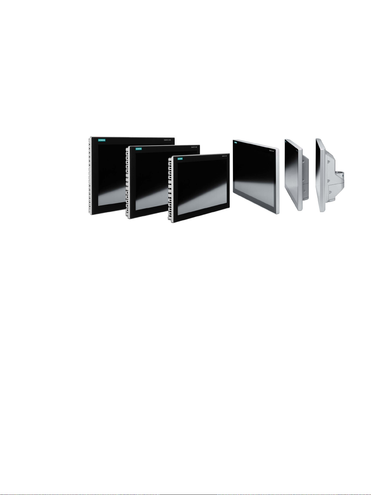
SIMATIC IFPs are industrial LCD monitors with a brilliant TFT display that can be connected
to SIMATIC IPCs and to almost all commercially available PCs.
Features of the built-in units
● Rugged front in different design versions
● Brilliant TFT display with high viewing angle, Full HD resolution and up to 16 million
colors
● Capacitive multi-touch screen in all sizes, switchable via software from multi-touch mode
to single-touch mode
● Can be placed up to 5 m from the IPC
● DVI-D and DisplayPort V1.2 interface
● Multi-monitoring support
● Backlighting can be dimmed via software
● Two USB 2.0 ports
● Power supply 24 V DC, AC power supply unit available as system component
● In installed condition, front degree of protection IP65 or Enclosure Type 4X/12 (indoor use
only, front face only)
Features of the extended versions
The extended versions have a DisplayPort V1.2 interface and the following features in
addition to the built-in devices:
● Possible via Transceiver Unit up to 100 m distance to the PC
IFP V2, IFP V2 PRO
Operating Instructions, 08/2019, A5E46641410-AA
9

Overview
1.1 Product description
Features of the PRO devices
The PRO devices are connected to a 24 V DC power supply and have the following features
in addition to the extended versions:
● All-round dust-proof and splash-proof with degree of protection IP65 and
Enclosure Type 4X/12 (indoor use only)
● Can be mounted directly on the machine
● Device versions for mounting:
– PRO device for pedestal (extendable, flange bottom)
– PRO device for support arm (not extendable, flange top)
– PRO device for support arm (extendable, round tube)
Adapters and adapter sets that can be ordered separately support mounting systems
from various manufacturers.
– Base adapter, included in the product package of PRO devices for pedestal
(extendable, flange bottom) and for support arm (not extendable, flange top).
– With PRO devices for support arm (extendable, round tube):
- Cover for the mechanical interface below, included in the product package
- Flange mount adapter available as accessory
IFP V2, IFP V2 PRO
10 Operating Instructions, 08/2019, A5E46641410-AA
Overview
Name
Figure
Number
DisplayPort cable, length 2 m
1
USB cable Type B connector - Type A connector, length 2 m
1
Ferrite for power supply cables, white
1
Ferrite for the Ethernet cable to the Transceiver Unit, black
1
Drivers" DVD
1
2
3
4
5
Only for extended versions and PRO devices
1.2 Scope of delivery of the IFPs
1.2 Scope of delivery of the IFPs
The product package includes the following components:
IFP
Installation instructions
(Quick Install Guide)
Accessory kit
"Mounting clips
1
and
power supply connector"
Strain relief plate 1
Including 3 screws T10,
M3x8
1
1
12
1
1
Base adapter 2
Cover for mechanical
3
interface
"Connecting cables"
4
accessory kit
Ferrites 5
"Documentation and
Only for built-in devices, not for PRO devices
Only with PRO devices for pedestal (extendable, flange bottom) and for support arm (not
extendable, flange top)
Only with PRO devices for support arm (extendable, round tube)
Only for standard versions
IFP V2, IFP V2 PRO
Operating Instructions, 08/2019, A5E46641410-AA
Including 4 screws T20,
M4x12
Including 4 screws T20,
M4x12
Includes software, drivers, and documentation 1
1
1
11
Overview
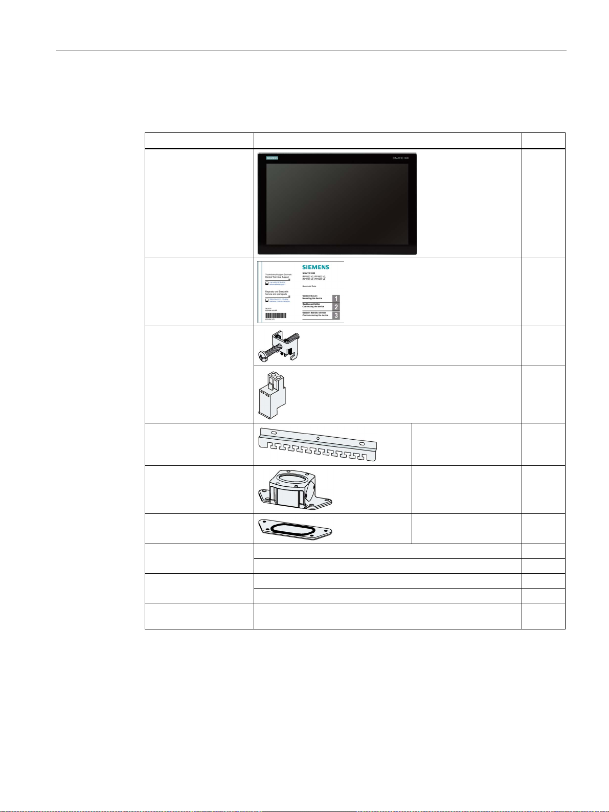
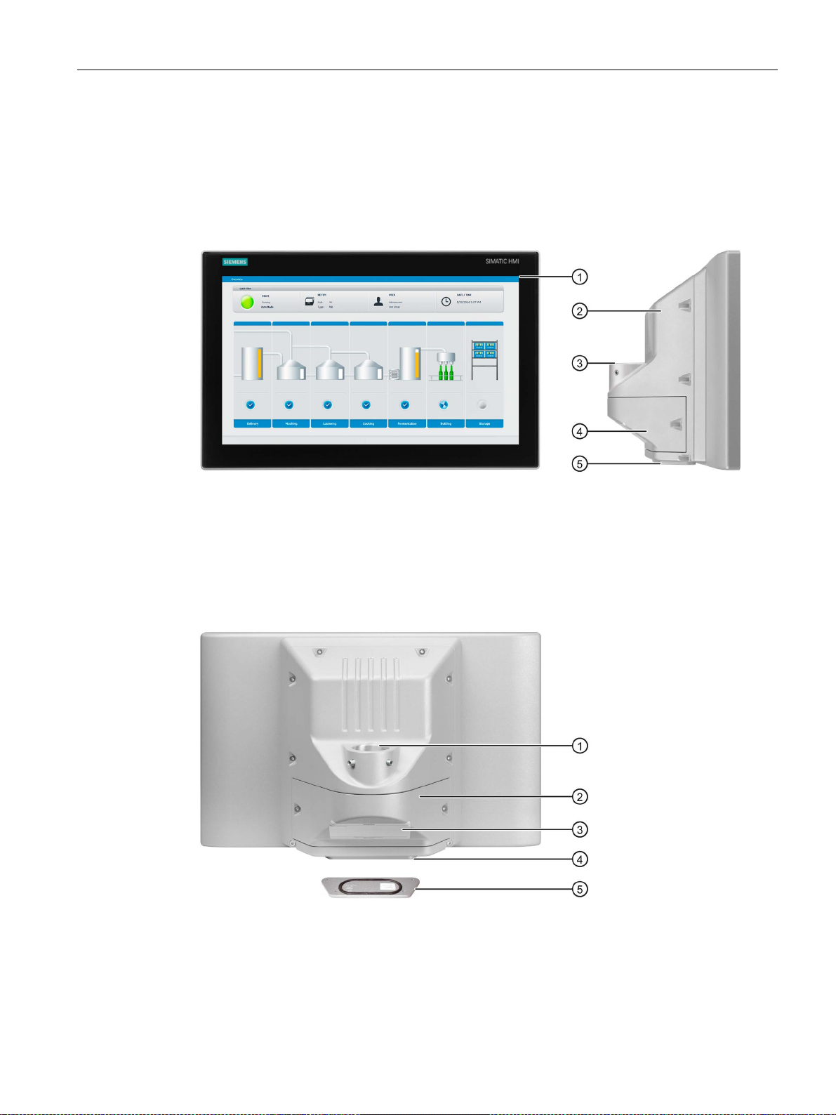
①
Display and capacitive multi-touch screen
②
Recesses for mounting clips
③
Mounting seal
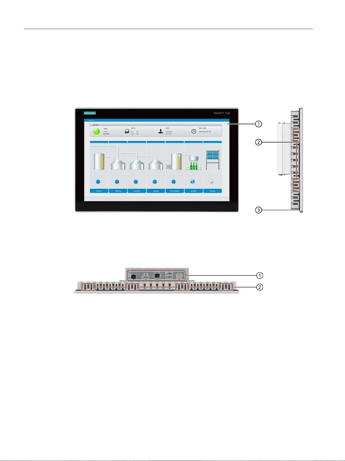
①
Interfaces
②
Recesses for mounting clips
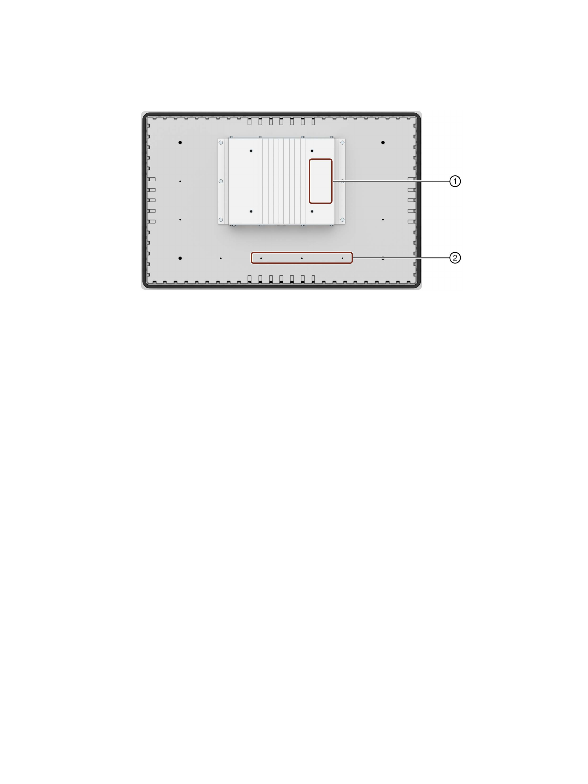
1.3 Structure of the built-in devices
1.3 Structure of the built-in devices
This section describes the structure of the built-in devices using the example of the
IFP1900 V2 extended.
Front view and side view
Bottom view
IFP V2, IFP V2 PRO
12 Operating Instructions, 08/2019, A5E46641410-AA
Overview
①
Position of rating plate
②
Threaded holes for fastening the strain relief plate
1.3 Structure of the built-in devices
Rear view
IFP V2, IFP V2 PRO
Operating Instructions, 08/2019, A5E46641410-AA
13
Overview
①
Display and capacitive multi-touch screen
②
Enclosure
③
Backplane cover
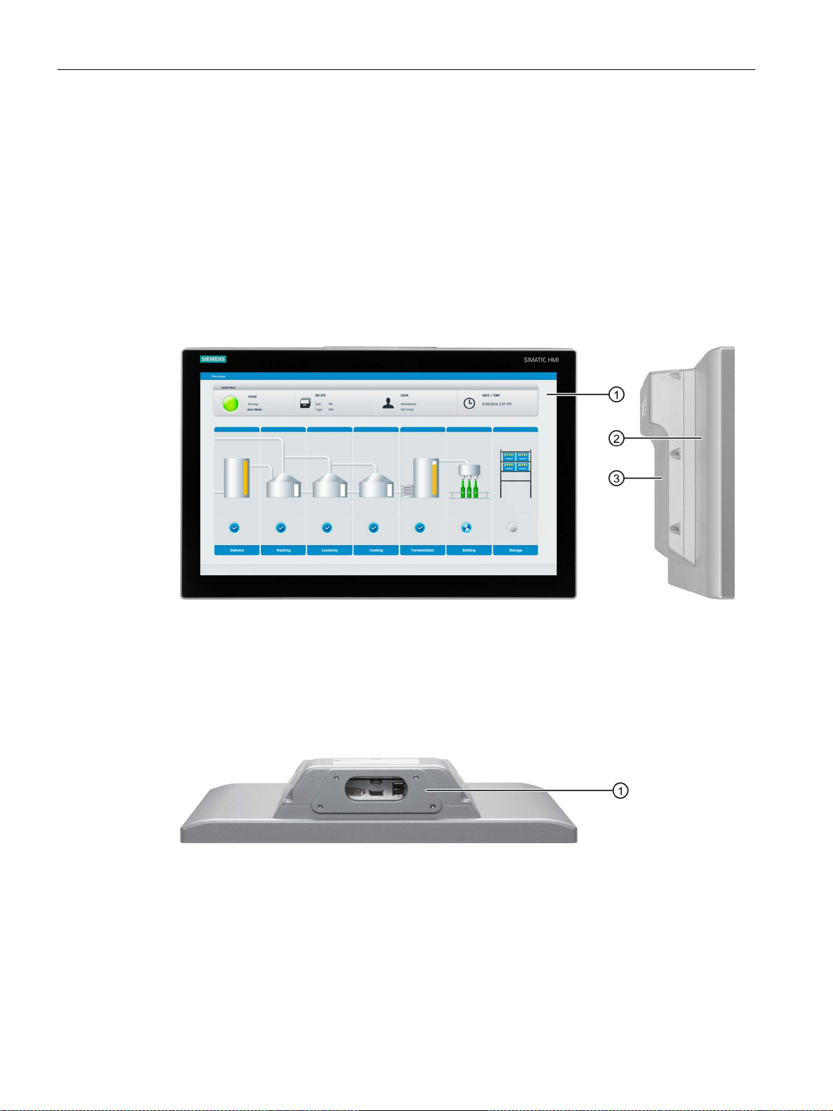
①
Mechanical interface for fastening
1.4 Design of the PRO devices
1.4 Design of the PRO devices
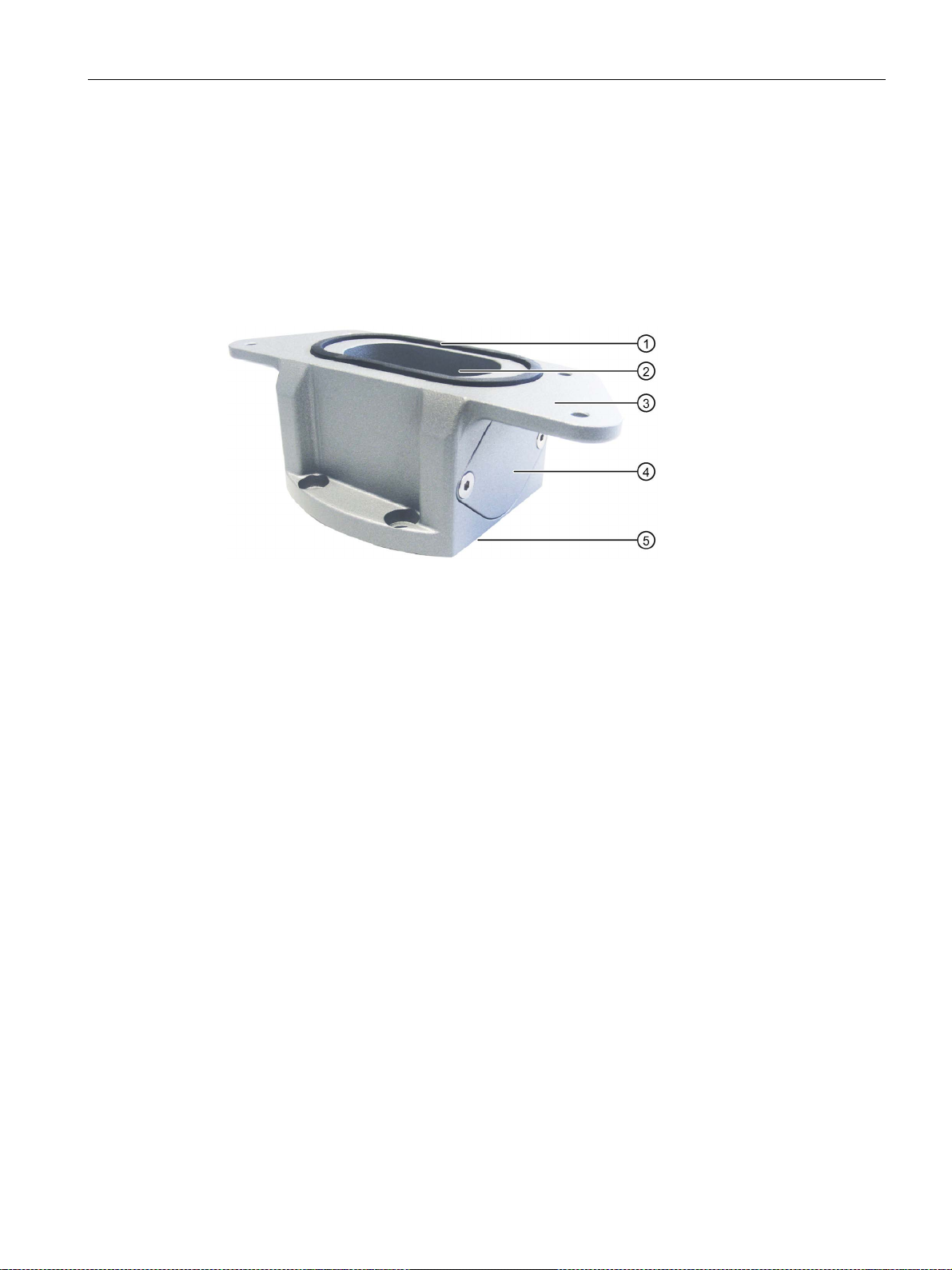
1.4.1 PRO devices for support arm (not extendable, flange top)
This section describes the structure of the PRO devices for support arm (not extendable,
flange top) using the example of the IFP1900 PRO for support arm (not extendable, flange
top).
Front view and side view
Top view
IFP V2, IFP V2 PRO
14 Operating Instructions, 08/2019, A5E46641410-AA
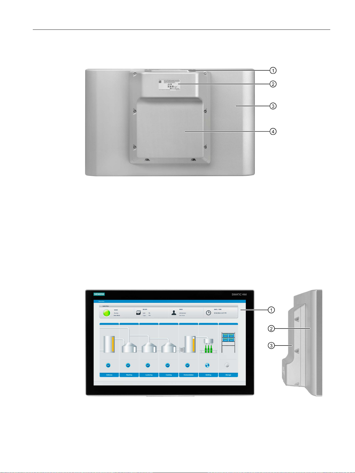
Overview
①
Mechanical interface for fastening
②
Rating plate
③
Enclosure
④
Backplane cover
①
Display and capacitive multi-touch screen
②
Enclosure
③
Backplane cover
1.4 Design of the PRO devices
Rear view
1.4.2 PRO devices for pedestal (extendable, flange bottom)
This section describes the structure of the PRO devices for pedestal (extendable, flange
bottom) using the example of the IFP1900 PRO for pedestal (extendable, flange bottom).
Front view and side view
IFP V2, IFP V2 PRO
Operating Instructions, 08/2019, A5E46641410-AA
15
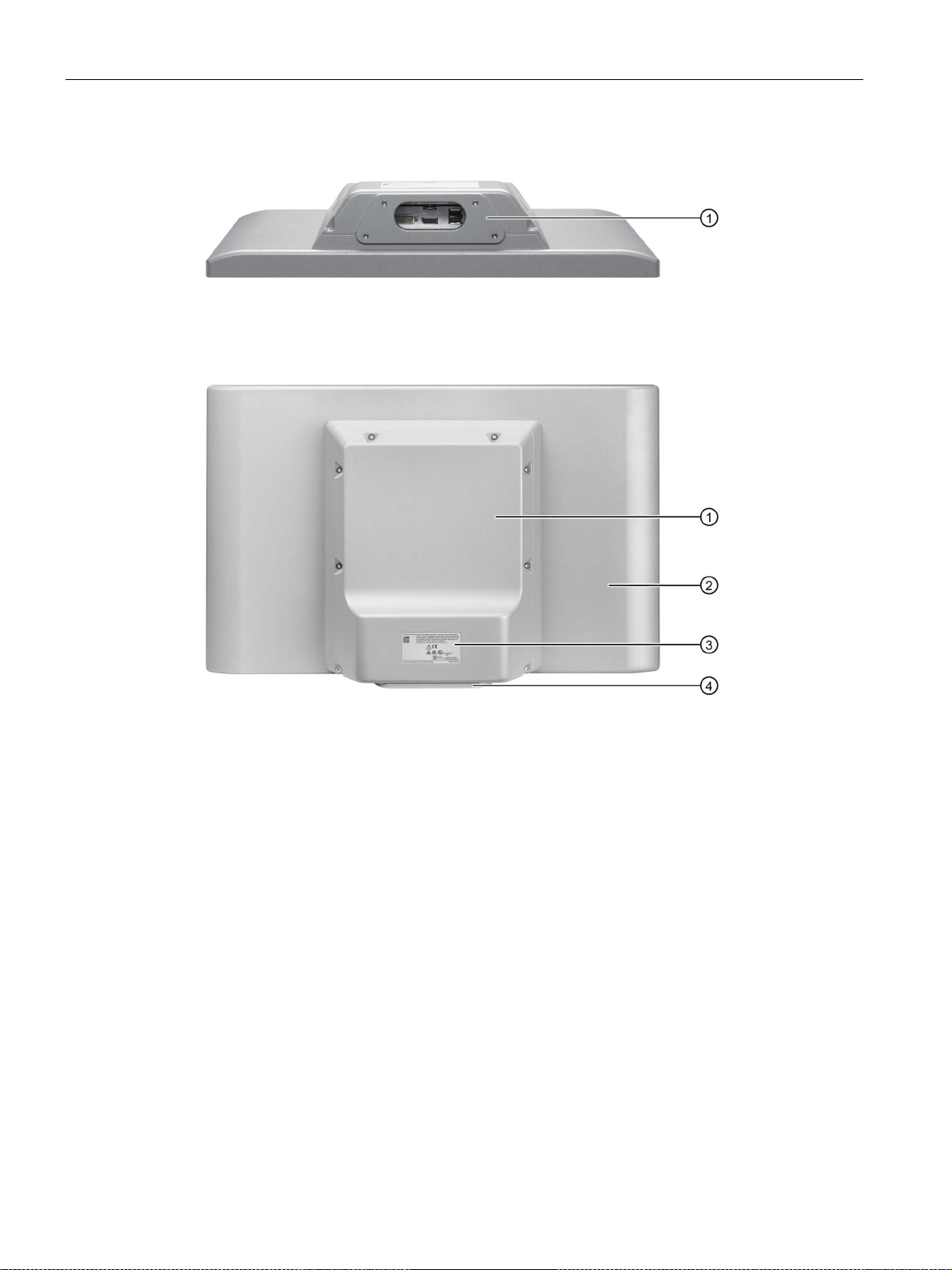
Overview
①
Mechanical interface for fastening
①
Backplane cover
②
Enclosure
③
Rating plate
④
Mechanical interface for fastening
1.4 Design of the PRO devices
Bottom view
Rear view
IFP V2, IFP V2 PRO
16 Operating Instructions, 08/2019, A5E46641410-AA
Overview
①
Display and capacitive multi-touch screen
②
Enclosure
③
Mechanical interface for fastening (round tube)
④
Terminal compartment cover
⑤
Mechanical interface to the optional Extension Unit or to the supplied cover
①
Mechanical interface for fastening (round tube)
②
Terminal compartment cover
③
Rating plate
④
Mechanical interface to the optional Extension Unit or to the supplied cover
⑤
Lower cover, included in the product package
1.4 Design of the PRO devices
1.4.3 PRO devices for support arm (extendable, round tube)
This section describes the structure of the PRO devices for support arm (extendable, round
tube) using the example of the IFP1500 PRO for support arm (extendable, round tube).
Front view and side view
Rear view
IFP V2, IFP V2 PRO
Operating Instructions, 08/2019, A5E46641410-AA
17
Overview
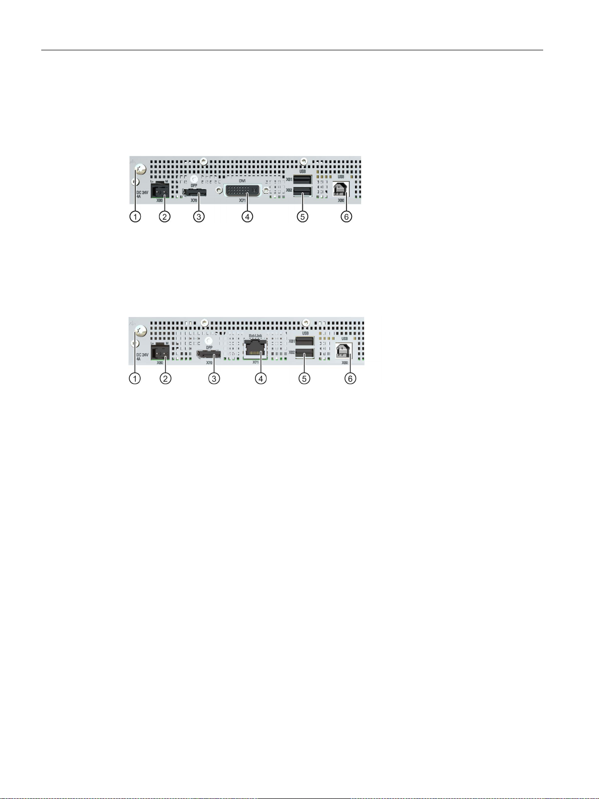
①
Connection for functional ground
④
X71 DVI-D interface
②
X80 connector for 24 V DC power supply
⑤
X61/X62 USB Type A
③
X70 DisplayPort interface
⑥
X60 USB Type B
①
Connection for functional ground
④
X63 RJ45 interface to the Transceiver Unit
②
X80 connector for 24 V DC power supply
⑤
X61/X62 USB Type A
③
X70 DisplayPort interface
⑥
X60 USB Type B
1.5 Interfaces
1.5 Interfaces
Standard versions
Extended versions and PRO devices
1.6 System components and accessories
System components are products that have been developed for a specific system and can
not be used in general, for example, like the base adapter. System components are always
directly related to a core product.
Accessories can typically be used for multiple devices from the same or different device
families, for example, batteries, touch pens or protective membranes.
IFP V2, IFP V2 PRO
18 Operating Instructions, 08/2019, A5E46641410-AA
Overview
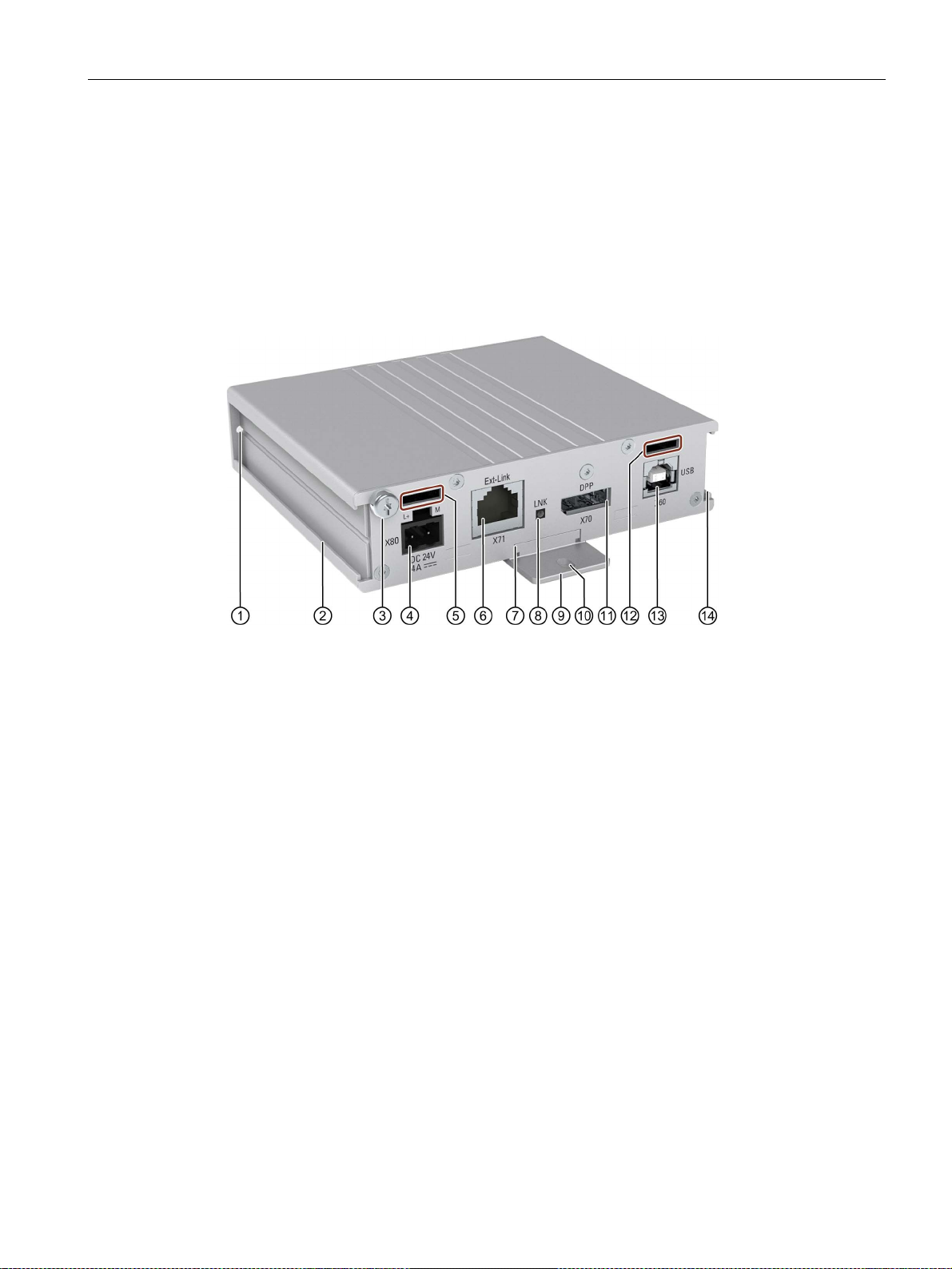
①
Hole for the screw to fasten the mounting rail
⑧
"LNK" LED
②
Guide for the "left" mounting rail
⑨
Mounting rail
③
Connection for functional ground
⑩
Lower elongated hole of the mounting rail
④
X80 connector for 24 V DC power supply
⑪
X70 DisplayPort interface
⑤
Opening for fastener for "left" strain relief
⑫
Opening for fastener for "right" strain relief
⑥
X71 RJ45 interface to the IFP
⑬
X60 USB Type B
⑦
Guide for the "rear" mounting rail
⑭
Guide for the "right" mounting rail
1.6 System components and accessories
1.6.1 System components for IFPs
Transceiver Unit for extended versions and PRO devices
With the Transceiver Unit you can bridge a distance of up to 100 m between a PC and an
extended version or a PRO device. The Transceiver Unit is mounted close to the PC.
The Transceiver Unit can be attached on a DIN rail or in various positions on a wall using the
fixing accessories supplied.
Article number of the Transceiver Unit: 6AV7860-3EH00-0AA0
Scope of delivery
● A Transceiver Unit
● One mounting rail for attachment to DIN rail or wall mounting
● Two retaining elements for strain relief
● One DisplayPort cable, length 0.5 m
● One USB cable Type B connector - Type A connector, length 0.5 m
● A power supply connector 24 V DC, 2-pin
● A ferrite for the power supply cables, white
● One ferrite for the Ethernet line to the IFP, black
IFP V2, IFP V2 PRO
Operating Instructions, 08/2019, A5E46641410-AA
19
Overview
WARNING
Do not use the power supply unit in hazardous areas.
1.6 System components and accessories
Functions of the "LNK" LED
● LED lit green: Active link available
● LED not illuminated: No active link available
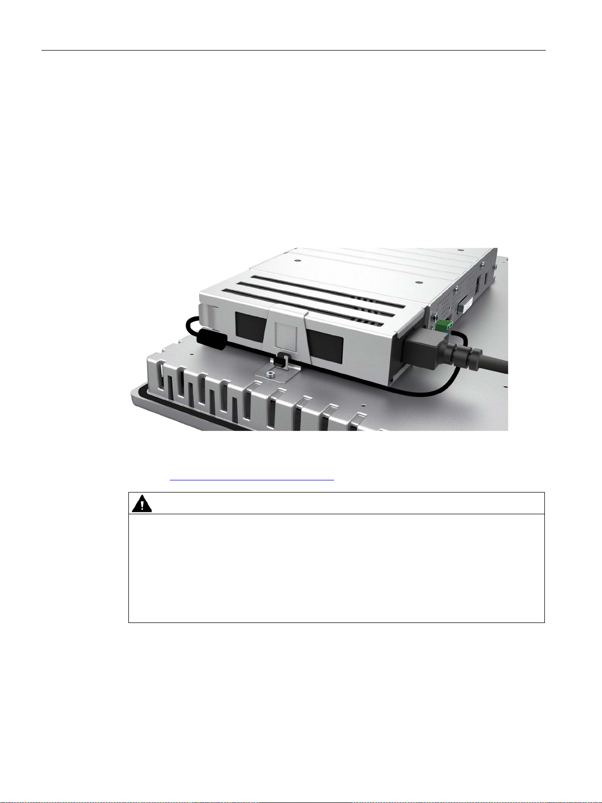
AC power supply unit for built-in devices
Connect a built-in device to the power supply via the AC power supply unit, input voltage
range 100 V to 240 V. Use the supplied fixing accessories to mount the AC power supply
unit on the rear of the built-in device.
Article number of the AC power supply unit: 6AV7860-3PA00-0AA0
You can find the documentation for the AC power supply unit with the article number on the
Internet (https://support.industry.siemens.com).
The power supply unit is not approved for use in hazardous areas. If the power supply unit
is mounted on a built-in device with Ex approval, the Ex approval of the built-in device
expires.
Operation of the power supply unit in a hazardous area may result in an explosion, death or
serious injury.
Never operate the power supply unit in a hazardous area.
IFP V2, IFP V2 PRO
20 Operating Instructions, 08/2019, A5E46641410-AA
Overview
①
Seal
②
Channel cable
③
Mechanical interface to the PRO device
④
Cover
⑤
Mechanical interface to the support arm or pedestal including seal
1.6 System components and accessories
1.6.2 System components for PRO devices
Base adapter
You use the base adapter to mount PRO devices for support arm (not extendable,
flange top) or for pedestal (extendable, flange bottom) on the support arm or on the pedestal.
A base adapter is included with the product package of the corresponding PRO device. The
base adapter can also be ordered separately.
Article number: 6AV7674-1KA00-0AA0
Adapter sets and couplings
The following mechanical adapter versions are also available for mounting a PRO device
for support arm (not extendable, flange top) or for pedestal (extendable, flange bottom) via
the base adapter:
● Adapter set VESA75 for VESA75-compatible systems, Article number
6AV7674-0KE00-0AA0
● Adapter set VESA100 for VESA100-compatible systems, Article number
6AV7674-0KD00-0AA0
In addition, other manufacturers offer support arm or pedestal systems with mechanical
interfaces or adapters for Siemens PRO devices, e.g. RITTAL, ROLEC, BERNSTEIN,
HASEKE, ROSE. Observe the specifications provided by the respective manufacturer.
IFP V2, IFP V2 PRO
Operating Instructions, 08/2019, A5E46641410-AA
21
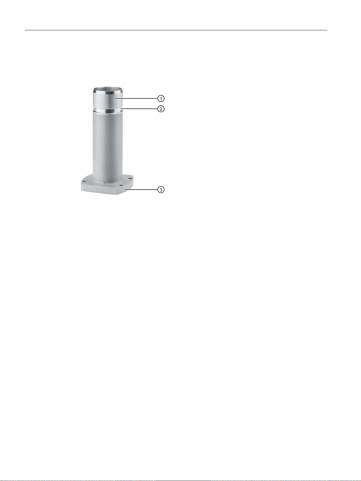
Overview
①
Flange mount adapter
②
Ring groove for fastening on PRO device with setscrews
③
Mechanical interface to support arm
1.6 System components and accessories
Flange mount adapter
A flange mount adapter is available for mounting a PRO device for support arm (extendable,
round tube).
Round tube plug
Article number: 6AV7674-1KF00-0AA0
If you do not need the mechanical interface of a PRO device for support arm (extendable,
round tube) you can install the round tube plug into the mechanical interface. With the round
tube plug, the degree of protection IP65 is maintained all around for the PRO device.
Article number: 6AV7674-1LB40-0AA0
IFP V2, IFP V2 PRO
22 Operating Instructions, 08/2019, A5E46641410-AA
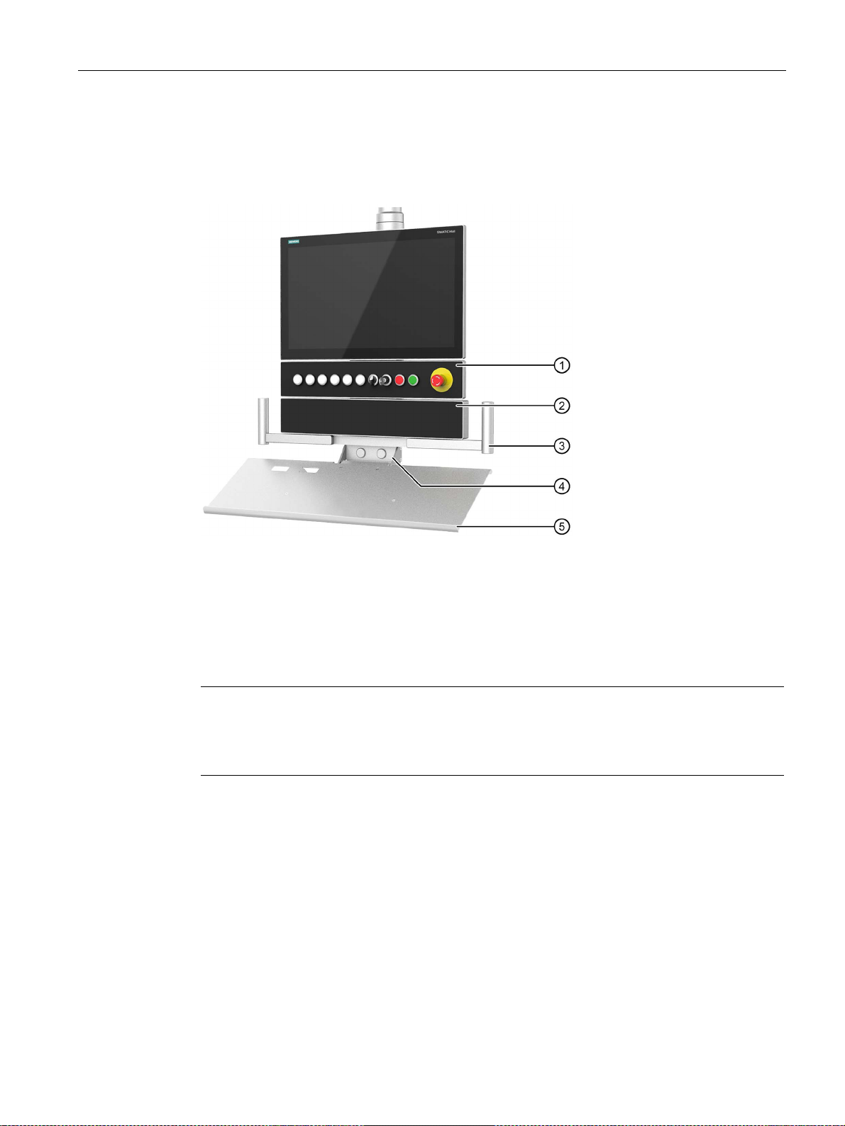
Overview
①
Extension Unit
stop button.
②
Extension Unit box
controls.
③
Handles, set to match the 22" PRO device
④
Keyboard tray for mounting the keyboard tray plate or installing a suitable keyboard
⑤
Keyboard tray plate
Note
Maximum two Extension Units permissible
A maximum of two Extension Units are permitted under a PRO device for
(extendable, flan
1.6 System components and accessories
Extensions for PRO devices:
The following example shows a PRO device for a support arm (extendable, round tube) with
Extension Unit, Extension Unit box as well as the PRO Options handles and keyboard tray
with keyboard tray plate.
, Example: Extension Unit 22" with eight operator controls including emergency
, deep empty enclosure, example: Extension unit box 22" without operator
pedestal
ge bottom) or for support arm (extendable, round tube).
Extension Unit
The Extension Unit is used to install additional operator controls below a SIMATIC PRO
device for pedestal (extendable, flange bottom) or for support arm (extendable, round tube).
The Extension Unit can be custom-equipped and is supplied without operator controls. The
front of the Extension Unit is fitted with pre-perforated installation points for operator controls.
The Extension Unit are available in four different sizes:
● Extension Unit 12", article number 6AV7674-1LA3x-0AA0
● Extension Unit 15", Article number 6AV7674-1LA4x-0AA0
● Extension Unit 19", Article number 6AV7674-1LA5x-0AA0
● Extension Unit 22", Article number 6AV7674-1LA6x-0AA0
IFP V2, IFP V2 PRO
Operating Instructions, 08/2019, A5E46641410-AA
23

Overview
Note
Only operator controls with Siemens approval may be installed in the Extension Unit.
1.6 System components and accessories
In each Extension Unit size, you have the flexibility to choose between the following interface
variants (x) for connection to the system:
● Hardwired (x=1)
● PROFINET (x=2)
● PROFIsafe (x=3)
In addition, different operator controls, such as emergency stop button, selector switch,
illuminated button, keyswitch and indicator light are available.
Extension Unit box
The Extension Unit box offers a deep empty housing to install larger customer-specific
components underneath a 16:9 SIMATIC PRO device for pedestal (extendable,
flange bottom) or for support arm (extendable, round tube).
The extension unit is supplied without operator controls; the front is not prepared for
installation of operator controls. The Extension Unit box are available in four different sizes:
● Extension Unit box 12", Article number 6AV7674-1LA30-0AA0
● Extension Unit box 15", Article number 6AV7674-1LA40-0AA0
● Extension Unit box 19", Article number 6AV7674-1LA50-0AA0
● Extension Unit box 22", Article number 6AV7674-1LA60-0AA0
Handles
The adjustable width handles make it easier to align or position the device as a whole
without touch the display of the PRO device.
Article number: 6AV7674-1LB10-0AA0
Keyboard tray
On the keyboard tray, you can install the keyboard tray plate or a suitable keyboard. In
addition, the keyboard tray has two face-side openings for USB interfaces and two rear-side
openings for cable glands.
Article number: 6AV7674-1NF01-0AA0
Keyboard tray plate
The keyboard tray plate offers enough space for keyboard and mouse.
Article number: 6AV7674-1NG00-0AA0
Replacement adapter
The replacement adapter makes it easier to dismantle and mount a SIMATIC PRO device
mounted above an Extension Unit.
Article number: 6AV7674-1LB50-0AA0
IFP V2, IFP V2 PRO
24 Operating Instructions, 08/2019, A5E46641410-AA

Overview
Note
This section contains a selection of accessories suitable for your device. You can find
additional versions of this selection and the complete accessories po
Mall on the Internet
(
such
Industry Mall under the respective article numbers.
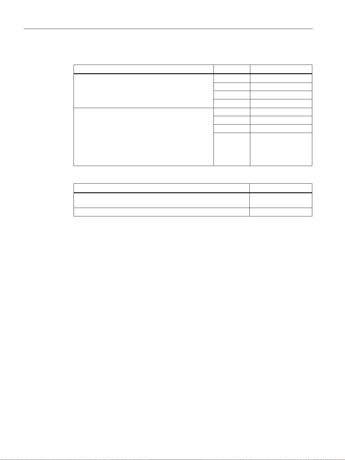
Name
Specification
Article number
3 m long
6AV7860-0BH30-0AA0
5 m long
6AV7860-0BH50-0AA0
3 m long
6AV7860-0DH30-0AA0
5 m long
6AV7860-0DH50-0AA0
3 m long
6AV7860-0CH30-0AA0
5 m long
6AV7860-0CH50-0AA0
Power supply connector 2-pin
Screw-type connection
6AV6671-8XA00-0AX0
Power supply connector 2x2-pin
Spring-loaded terminals
6ES7193-4JB00-0AA0
screen
Name
Article number
Set with steel mounting clips
6AV6671-8XK00-0AX3
1.6 System components and accessories
Additional information
Additional Extension Units and information on system components for all-round protected
devices with degree of protection IP65 and Enclosure Type 4X/12 (indoor use only) are
available on the Internet
(https://mall.industry.siemens.com/mall/en/WW/Catalog/Products/10268745).
1.6.3 Accessories
Each device comes with an accessory pack containing the necessary accessories.
rtfolio in the Industry
https://mall.industry.siemens.com/mall/en/WW/Catalog/Products/10144445). Details
as the delivery quantity and technical specifications of accessories can be found in the
Accessories for all IFPs
DVI line
DisplayPort line
USB cable
Type A connector - Type B connector
Touch pen For capacitive and resistive touch
Accessories for built-in devices
6AV2181-8AV20-0AX0
IFP V2, IFP V2 PRO
Operating Instructions, 08/2019, A5E46641410-AA
25
Overview
Name
Specification
Article number
10 m long
6AV7860-0EH01-0AA0
15 m long
6AV7860-0EH01-5AA0
20 m long
6AV7860-0EH02-0AA0
30 m long
6AV7860-0EH03-0AA0
10 m long
6AV7860-1EX21-0AB1
15 m long
6AV7860-1EX21-5AB1
20 m long
6AV7860-1EX22-0AB1
Name
Article number
6AV7860-1EY00-0AA0
Cat. 6A plug RJ45, suitable for Cat.6A Ethernet cable 6XV1878-2A
6AV7860-1EY00-0AA0
1.6 System components and accessories
Accessories for extended versions and PRO devices
Cat. 6A Ethernet cable
Cable set, consisting of
• Transceiver Unit with:
– Two ferrites
– USB cable, length 0.5 m Type A connector -
Type B connector
– DisplayPort cable, length 0.5 m
• Cat. 6A Ethernet cable, length see "Specification"
Use the following components to pre-assemble longer or individual cable lengths:
30 m long 6AV7860-1EX23-0AB1
Cat. 6A Ethernet cable, sold by the meter, for connection to Cat. 6A plug
6XV1878-2A
IFP V2, IFP V2 PRO
26 Operating Instructions, 08/2019, A5E46641410-AA

2
WARNING
The device may only be used in machines which comply with the Machinery Directive
NOTICE
Observe immunity to high-frequency radiation
2.1 General safety instructions
The device is designed for use in the industrial sector for operating and monitoring plant
processes.
Machinery Directive
The Machinery Directive specifies precautions to be taken when commissioning and
operating machinery within the European Economic Area.
Failure to follow these precautions is a breach of the Machinery Directive. Such failure may
also cause personal injury and damage depending on the machine operated.
The machine in which the HMI device is to be operated must conform to Directive
2006/42/EC.
Observe the safety and accident prevention instructions applicable to your application in
addition to the safety information given in the device documentation.
Strong high-frequency radiation
The device has an increased immunity to high frequency radiation according to the
specifications on electromagnetic compatibility in the technical specifications.
Radiation exposure in excess of the specified immunity limits can impair device functions
and result in malfunctions and therefore injuries or damage.
Read the information on immunity to high frequency radiation in the technical specifications.
IFP V2, IFP V2 PRO
Operating Instructions, 08/2019, A5E46641410-AA
27

Safety information
WARNING
The built-in device is an open equipment at the rear
The enclosure, the cabinet or the electrical operating rooms must provide protection against
Electrocution risk when control cabinet is open
not
WARNING
The device constitutes open equipment
rotection against
Electrocution risk when control cabinet is open
not
2.1 General safety instructions
Additional notes for built-in units
The built-in device is an open equipment at the rear. This means that you have to integrate
the built-in device into an enclosure or a cabinet, where the built-in device is operated via
the front panel.
electric shock and the spread of fire. The requirements regarding the mechanical strength
must also be taken into account.
Access to the enclosure or cabinet in which the built-in device is installed should only be
possible by means of a key or tool and for trained and qualified personnel.
When you open the control cabinet, there may be a dangerous voltage at certain areas or
components.
If you touch these areas or components, you may be killed by electric shock.
Disconnect the cabinet from the mains before opening it. Do
system component during operation.
Additional information for the Transceiver Unit
The device is open equipment. This means that the device may only be integrated in an
enclosure or cabinet.
The enclosure, the cabinet or the electrical operating rooms must provide p
electric shock and the spread of fire. The requirements regarding the mechanical strength
must also be considered.
Access to the enclosure or cabinet in which the device is installed should only be possible
by means of a key or tool and for trained and qualified personnel.
When you open the control cabinet, there may be a dangerous voltage at certain areas or
components.
If you touch these areas or components, you may be killed by electric shock.
plug in or pull out the
Disconnect the cabinet from the mains before opening it. Do
components during operation.
IFP V2, IFP V2 PRO
28 Operating Instructions, 08/2019, A5E46641410-AA
plug in or pull out system

Safety information
2.1 General safety instructions
ESD
An electrostatically sensitive device is equipped with electronic components. Due to their
design, electronic components are sensitive to overvoltage and thus to the discharge of
static electricity. Note the corresponding regulations when handling ESD.
Industrial Security
Siemens provides products and solutions with industrial security functions that support the
secure operation of plants, systems, machines and networks.
In order to protect plants, systems, machines and networks against cyber threats, it is
necessary to implement – and continuously maintain – a holistic, state-of-the-art industrial
security concept. Siemens’ products and solutions constitute one element of such a concept.
Customers are responsible for preventing unauthorized access to their plants, systems,
machines and networks. Such systems, machines and components should only be
connected to an enterprise network or the internet if and to the extent such a connection is
necessary and only when appropriate security measures (e.g. firewalls and/or network
segmentation) are in place.
For additional information on industrial security measures that may be implemented, please
visit (http://www.siemens.com/industrialsecurity).
Siemens’ products and solutions undergo continuous development to make them more
secure. Siemens strongly recommends that product updates are applied as soon as they are
available and that the latest product versions are used. Use of product versions that are no
longer supported, and failure to apply latest updates may increase customer’s exposure to
cyber threats.
To stay informed about product updates, subscribe to the Siemens Industrial Security RSS
Feed under (http://www.siemens.com/industrialsecurity).
Disclaimer for third-party software updates
This product includes third-party software. Siemens AG only provides a warranty for
updates/patches of the third-party software, if these have been distributed as part of a
Siemens software update service contract or officially released by Siemens AG. Otherwise,
updates/patches are undertaken at your own risk. You can find more information about our
Software Update Service offer on the Internet at Software Update Service
(http://www.automation.siemens.com/mcms/automation-software/en/software-update-
service).
Notes on protecting administrator accounts
A user with administrator privileges has extensive access and manipulation options in the
system.
Therefore, ensure there are adequate safeguards for protecting the administrator accounts
to prevent unauthorized changes. To do this, use secure passwords and a standard user
account for normal operation. Other measures, such as the use of security policies, should
be applied as needed.
IFP V2, IFP V2 PRO
Operating Instructions, 08/2019, A5E46641410-AA
29

Safety information
NOTICE
Device approved for indoor use only
Note
Operate the device only in a normal atmospheric environment
The technical characteristics of the device described in the operating instructions are
gu
composition.
Note
The device is intended for
IEC/EN
•
•
•
Additional information is available in the section "
2.2 Notes about usage
2.2 Notes about usage
The device may be damaged if operated outdoors.
Operate the device indoors only ("Indoor use only").
aranteed if you operate the device in normal ambient air conditions with usual air
operation in an SELV/PELV circuit according to
61010-2-201 in a dry environment, which means for the various device types:
Built-in devices: dry environment on the rear of the device
PRO devices: dry environment inside the housing
Transceiver Unit: dry environment all around
Industrial applications
The device is designed for industrial use. It conforms to the following standards:
● Requirements for interference emissions EN 61000-6-4
● Requirements for interference immunity EN 61000-6-2
Use in mixed-use zone
Under certain circumstances you can use the device in a mixed-use zone. A mixed-use zone
is used for housing and commercial operations that do not have a significant impact on
residents.
When you use the device in a mixed-use zone, you must ensure that the limits of the generic
standard EN 61000-6-3 regarding emission of radio frequency interference are observed.
Suitable measures for achieving these limits for use in a mixed-use zone include:
● Installation of the device in grounded control cabinets
● Use of filters in electrical supply lines
Individual acceptance is required.
Operating Conditions (Page 92)".
IFP V2, IFP V2 PRO
30 Operating Instructions, 08/2019, A5E46641410-AA
 Loading...