

Siemens SIMATIC IFP1900 PRO,SIMATIC HMI IFP1900 PRO,SIMATIC HMI IFP2200 PRO Quick Install Manual
Gerät einbauen
1
2
3
1
4
2
6
7
2
1
4
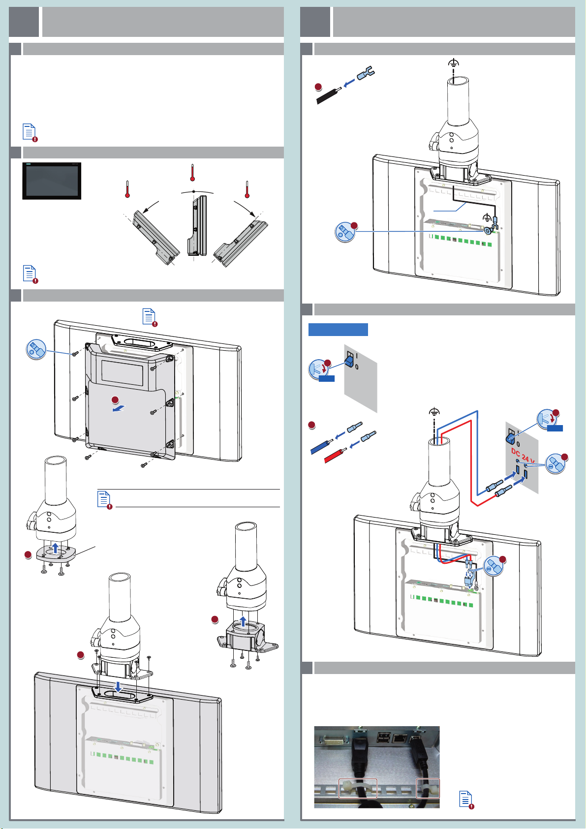
Mounting the device
1
Gerät anschließen
Connecting the device
2
1.1
Qualifiziertes Personal – Qualified Personnel
WICHTIG: Beachten Sie alle dem Gerät beiliegenden Dokumente und die Betriebsanleitung, bevor
Sie das Gerät einbauen und anschließen. Die vollständige Dokumentation des Geräts finden Sie auf
der beiliegenden DVD "Documentation and Drivers" und im Internet
(http://www.siemens.de/simatic-ipc-doku-portal).
IMPORTANT: observe all documents enclosed with the device and the operating instructions manual
before mounting and connecting the device. You find the complete documentation of the device on
the enclosed " Documentation and Drivers" DVD and on the internet
(http://www.siemens.com/simatic-ipc-doku-portal).
Das Handbuchsymbol weist auf detaillierte Informationen in der Betriebsanleitung hin.
The manual symbol refers to detailed information in the operating instructions.
Zulässige Einbaulagen – Valid Mounting positions
1.2
45 °C
0 °C
Informationen zu weiteren Gerätevarianten
Information on additional device variants
Gerät installieren – Installing the device
1.3
45 °C
0 °C
0°- 45° 0°- 45°
Informationen zu weiteren Montagevarianten
Information on additional mounting variants
8 x
T20
45 °C
0 °C
Funktionserde anschließen – Connecting functional ground
2.1
T20
DC 24 V
Supply
M4
2.5 mm²
Das Gerät darf nur an eine Stromversorgung DC 24 V (-20 % / +20 %)
angeschlossen werden, die den Anforderungen einer sicheren
Kleinspannung (SELV) gemäß der IEC/ EN/DIN EN/UL 60950‑1 entspricht.
Die Stromversorgung muss die Anforderung NEC Class 2 bzw. LPS gemäß
der IEC/EN/DIN EN/UL 60950-1 erfüllen.
The device must only be connected to a 24 VDC power supply
(-20 % / +20 %) that meets the requirements of safe extra-low voltage
(SELV) according to IEC/EN/DIN EN/UL 60950-1.
Power
The power supply must meet the requirement NEC Class 2 or LPS
according to the IEC/EN/DIN EN/UL 60950-1.
Stromversorgung anschließen – Connecting the power supply
2.2
24 VDC
0/OFF
0/OFF
4 Schrauben/screws
M6 x 12
Beachten Sie die Drehmomentangaben in der Betriebsanleitung
Observe the torque specifications in the operating instructions
Falls in Adapterset vorhanden
If contained in adapter set
4 Schrauben/screws
M4 x 12
4 Schrauben/screws
M6 x 12
M
L+
Leitungen sichern – Securing the cables
2.3
Sichern Sie die angeschlossenen Leitungen zur Zugentlastung mit Kabelbindern an den markierten
Befestigungselementen. Achten Sie darauf, dass die Leitungen durch die Kabelbinder nicht gequetscht
werden. Beispiel:
Use cable ties to secure the connected cables to the selected fixing elements for strain relief.
Make sure that the cables are not crushed by the cable tie. Example:
Weitere Beispiele
Additional examples
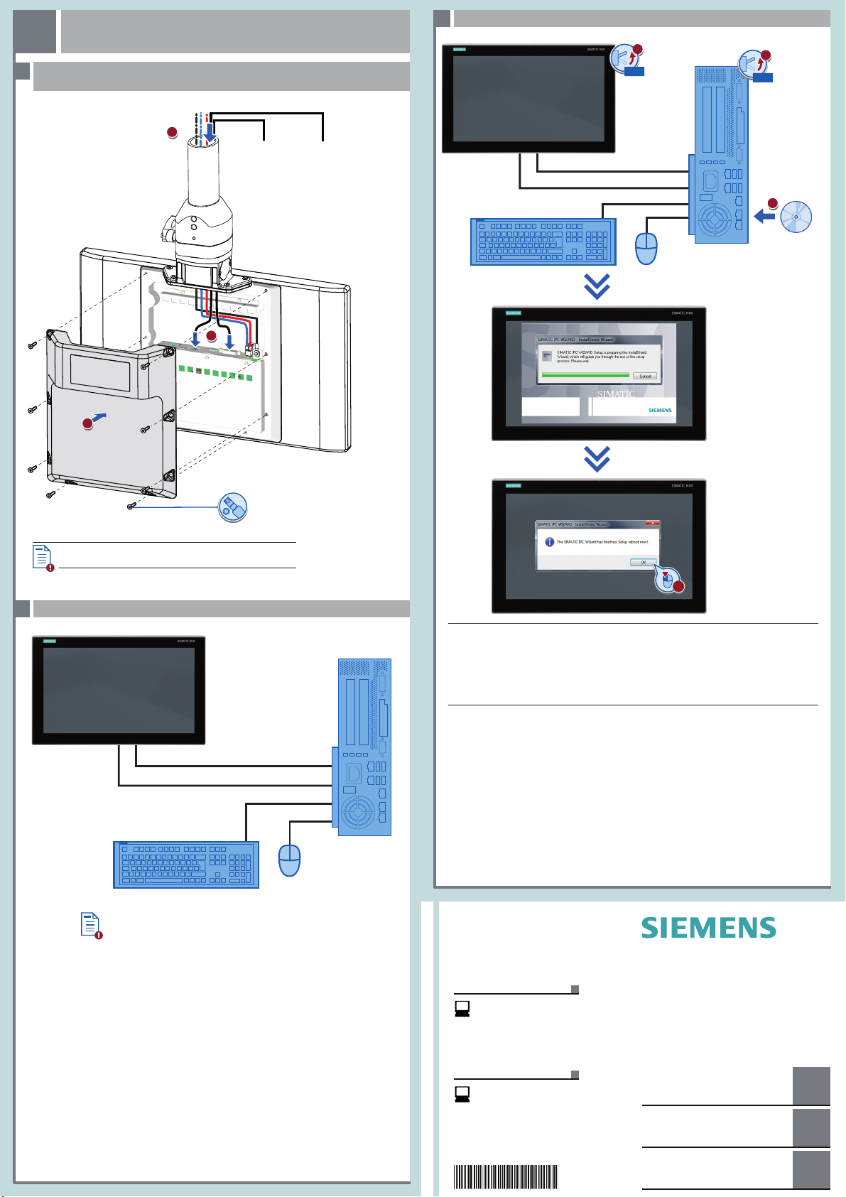
Gerät in Betrieb nehmen
3
4
2
4
1
1
2
3
Commissioning the device
3
DVI-D/DisplayPort und USB-Leitungen anschließen, Anschlussfach schließen -
3.1
Connecting DVI-D/DisplayPort and USB cables, closing the compartment
DVI-D/DisplayPort
USB
3.3 Erstinbetriebnahme – Initial commissioning
Power supply
1/ON
DVI-D/DisplayPort
USB
PC
1/ON
Documentation
and Drivers
Beachten Sie die Drehmomentangaben in der Betriebsanleitung
Observe the torque specifications in the operating instructions
PC anschließen – Connecting a PC
3.2
8 x
T20
DVI-D/DisplayPort
USB
PC
Abbildungen
Das vorliegende Dokument enthält Abbildungen zu den beschriebenen Geräten und Zubehör.
Die Abbildungen können bezogen auf das geliefer te Gerät und Zubehör in Einzelheiten abweichen.
Illustrations
This document contains illustrations of the described devices and accessories.
The illustrations may deviate from the particularities of the delivered device and accessories.
Haftungsausschluss
Wir haben den Inhalt der Druckschr ift auf Übereinstimmung mit der beschriebenen Hard- und
Software geprüft. Dennoch können Abweichungen nicht ausgeschlossen werden, so dass wir für
die vollständige Übereinstimmung keine Gewähr übernehmen. Die A ngaben in dieser Druckschrift
werden regelmäßig überprüft, notwendige Korrekturen sind in den nachfolgenden Auf lagen
enthalten.
Disclaimer of Liability
We have reviewed the contents of this publication to ensure consistency with the hardware and
software described. Since variance cannot be precluded entirely, we cannot guarantee full
consistency. However, the information in this publication is reviewed regularly and any necessary
corrections are included in subsequent editions.
Siemens AG
Industry Sector
Postfach 48 48
90026 NÜRNBERG
Beträgt die Entfernung zwischen Flat Panel und PC mehr als 5 m, dann
verbinden Sie Flat Panel und PC mit USB-Senderbaugruppe über die
USB-Link-Schnittstelle.
If the distance bet ween the Flat Panel and the PC is greater than 5 m,
connect the Flat Panel and PC with USB transmitter module by means of the
USB-Link interface.
Technische Support-Zentrale
Central Technical Support
www.siemens.com/
automation/support
Reparatur und Ersatzteile
Service and spare parts
https://support.industr y.
siemens.com/sc/de/en/sc
06/2015
A5E35920911-AA
SIMATIC Industrial Flat Panels
IFP1900 PRO
Quick Install Guide
Gerät einbauen
Mounting the device
Gerät anschließen
Connecting the device
Gerät in Betrieb nehmen
Commissioning the device
1
2
3
 Loading...