

Siemens SIMATIC IFP1900 ETH, SIMATIC IFP2200, SIMATIC IFP1900 PRO, SIMATIC IFP2200 ETH, SIMATIC IFP2200 PRO Operating Instructions Manual
...
___________________
___________________
___________________
___________________
___________________
___________________
___________________
___________________
___________________
___________________
___________________
SIMATIC HMI
Industrial Flat Panels
IFP, IFP PRO, IFP ETH
Operating Instructions
11/2017
A5E31298376
Preface
Overview
1
Safety information
2
Installing and connecting the
device
3
Commissioning the device
4
Operating the device
5
Maintaining and servicing
your device
6
Technical information
7
Technical Support
A
Markings and symbols
B
List of abbreviations
C
-AH
Siemens AG
Division Digital Factory
Postfach 48 48
90026 NÜRNBERG
GERMANY
Ⓟ
Copyright © Siemens AG 2017.
All rights reserved
Legal information
Warning notice system
DANGER
indicates that death or severe personal injury will result if proper precautions are not taken.
WARNING
indicates that death or severe personal injury may result if proper precautions are not taken.
CAUTION
indicates that minor personal injury can result if proper precautions are not taken.
NOTICE
indicates that property damage can result if proper precautions are not taken.
Qualified Personnel
personnel qualified
Proper use of Siemens products
WARNING
Siemens products may only be used for the applications described in the catalog and in the relevant technical
maintenance are required to ensure that the products operate safely and without any problems. The permissible
ambient conditions must be complied with. The information in the relevant documentation must be observed.
Trademarks
Disclaimer of Liability
This manual contains notices you have to observe in order to ensure your personal safety, as well as to prevent
damage to property. The notices referring to your personal safety are highlighted in the manual by a safety alert
symbol, notices referring only to property damage have no safety alert symbol. These notices shown below are
graded according to the degree of danger.
If more than one degree of danger is present, the warning notice representing the highest degree of danger will
be used. A notice warning of injury to persons with a safety alert symbol may also include a warning relating to
property damage.
The product/system described in this documentation may be operated only by
task in accordance with the relevant documentation, in particular its warning notices and safety instructions.
Qualified personnel are those who, based on their training and experience, are capable of identifying risks and
avoiding potential hazards when working with these products/systems.
Note the following:
documentation. If products and components from other manufacturers are used, these must be recommended
or approved by Siemens. Proper transport, storage, installation, assembly, commissioning, operation and
All names identified by ® are registered trademarks of Siemens AG. The remaining trademarks in this publication
may be trademarks whose use by third parties for their own purposes could violate the rights of the owner.
We have reviewed the contents of this publication to ensure consistency with the hardware and software
described. Since variance cannot be precluded entirely, we cannot guarantee full consistency. However, the
information in this publication is reviewed regularly and any necessary corrections are included in subsequent
editions.
for the specific
11/2017 Subject to change

Preface
Basic knowledge required
Scope of the operating instructions
Scope of this documentation
Conventions
These operating instructions contain all the information you need for commissioning and
operation of the SIMATIC Industrial Flat Panel IFP.
It is intended both for programming and testing personnel who commission the device and
connect it with other units (automation systems, programming devices), as well as for service
and maintenance personnel who install add-ons or carry out fault/error analyses.
A solid background in personal computers and Microsoft operating systems is required to
understand this manual. General knowledge in the field automation control engineering is
recommended.
These operating instructions apply to the following Industrial Flat Panels with the order
numbers 6AV7863-.....-....:
● SIMATIC IFP1500, IFP1900, IFP2200
● SIMATIC IFP1900 ETH, IFP2200 ETH
● SIMATIC IFP1900 PRO, IFP2200 PRO
The SIMATIC Industrial Flat Panel is supplied with the following documents:
● In printed form: Quick Install Guide for the device, Installation and Commissioning
Instructions
● Electronically as PDF file on the "Documentation and Drivers" CD/DVD:
– Operating instructions Industrial Flat Panel IFP1500, IFP1900, IFP2200,
IFP1900 ETH, IFP2200 ETH, IFP1900 PRO, IFP2200 PRO
– Operating manual SIMATIC Industry PC Panel Drivers and Tools PDT
You can find the operating manual in the PDT installation directory after installing
PDT.
IFP, IFP PRO, IFP ETH
Operating Instructions, 11/2017, A5E31298376-AH
In these operating instructions, the SIMATIC IFP is also referred to as "Flat Panel" or
"device".
The devices SIMATIC IFP1900 ETH and IFP2200 ETH are also referred to as "Ethernet
Monitor" and "ETH version".
3

Preface
Figures
History
Edition
Comment
09/2012
First Edition
11/2014
Update with IPC Wizard 2.1 and corrections
07/2015
Corrections
07/2016
The description of the following devices has been added:
aluminum housing updated.
A touch device generally refers to a device with a touch screen, as opposed to a pure
"display device". Touch screen is the general term for a capacitive multi-touch screen and
resistive single touch screen.
The devices IFP1500, IFP1900, IFP2200, IFP1900 ETH and IFP2200 ETH are referred to as
"built-in units".
The devices IFP1900 PRO and PRO IFP2200 are referred to as "PRO devices".
At some places in these operating instructions, the general term "Windows Embedded
Standard" is used to refer to "Windows Embedded Standard 2009" and "Windows
Embedded Standard 7". "Windows 7" is used as an abbreviation for "Windows 7 Ultimate".
This manual contains figures of the described devices. The supplied device may differ in
some details from the figures. Within some of the figures, one device is used to represent all
Industrial Flat Panels.
The following earlier release versions of these operating instructions have been published:
06/2014 Description of devices with capacitive multi-touch screen
06/2015 The description of the following devices has been added:
• SIMATIC IFP1900 PRO for pedestal (extendable, flange bottom)
• SIMATIC IFP1900 PRO for support arm (not extendable, flange top)
• SIMATIC IFP1900 ETH, IFP2200 ETH
• SIMATIC IFP1900 PRO for support arm (extendable, round tube)
• SIMATIC IFP2200 PRO for pedestal (extendable, flange bottom)
• SIMATIC IFP2200 PRO for support arm (not extendable, flange top)
• SIMATIC IFP2200 PRO for support arm (extendable, round tube)
11/2016 Additions:
• System components for PRO devices: Extension Unit
• Mounting of PRO devices for support arm (extendable, round tube) on a
48.3 mm round tube
• Information on USB interfaces of Ethernet Monitors
• Information about standards, certificates and securing of cables for Ex ap-
proval
11/2017 Corrections
SIMATIC IFP1900 PRO and SIMATIC IFP2200 PRO: Dimensions for die-cast
IFP, IFP PRO, IFP ETH
4 Operating Instructions, 11/2017, A5E31298376-AH

Table of contents
Preface ........................................................................................................................................ 3
1 Overview ...................................................................................................................................... 9
2 Safety information ....................................................................................................................... 29
3 Installing and connecting the device .............................................................................................. 37
1.1 Product description .............................................................................................................. 9
1.2 Scope of delivery ............................................................................................................... 12
1.3 Design of the built-in units ................................................................................................. 13
1.3.1 IFP1500/1900/2200 Multitouch, IFP1900/2200 ETH .......................................................... 13
1.3.2 IFP1500/1900/2200 Touch ................................................................................................ 15
1.3.3 IFP1500 Touch/Key ........................................................................................................... 16
1.3.4 Interfaces .......................................................................................................................... 16
1.3.4.1 Standard versions ............................................................................................................. 16
1.3.4.2 Ethernet Monitor devices ................................................................................................... 17
1.3.4.3 Extended versions ............................................................................................................. 17
1.4 Design of the PRO devices ................................................................................................ 18
1.4.1 PRO devices for support arm (not extendable, flange top) ................................................. 18
1.4.2 PRO devices for pedestal (extendable, flange bottom) ....................................................... 19
1.4.3 PRO devices for support arm (extendable, round tube) ...................................................... 21
1.4.4 Interfaces .......................................................................................................................... 22
1.5 System components and accessories ................................................................................ 23
1.5.1 System components for PRO devices ................................................................................ 23
1.5.2 Accessories ....................................................................................................................... 27
2.1 General safety instructions ................................................................................................ 29
2.2 Notes about usage ............................................................................................................ 31
2.3 Use in hazardous areas ..................................................................................................... 35
3.1 Preparing for installation .................................................................................................... 37
3.1.1 Checking the delivery package .......................................................................................... 37
3.1.2 Built-in unit ........................................................................................................................ 38
3.1.2.1 Permitted mounting positions ............................................................................................. 38
3.1.2.2 Checking clearances ......................................................................................................... 40
3.1.2.3 Preparing the mounting cutout ........................................................................................... 41
3.1.2.4 Labeling the function keys ................................................................................................. 42
3.1.3 PRO devices ..................................................................................................................... 44
3.1.3.1 Permitted mounting positions ............................................................................................. 44
3.2 Installing the built-in unit .................................................................................................... 44
3.2.1 Notes on installation .......................................................................................................... 44
3.2.2 Mounting clips or mounting brackets, position for IP65 ....................................................... 45
3.2.3 Fastening the device with mounting clips or mounting brackets .......................................... 47
3.2.4 Position of the mounting clips for IP66-complaint installation .............................................. 48
IFP, IFP PRO, IFP ETH
Operating Instructions, 11/2017, A5E31298376-AH
5

Table of contents
4 Commissioning the device ........................................................................................................... 71
5 Operating the device ................................................................................................................... 73
6 Maintaining and servicing your device ........................................................................................... 81
3.3 Mounting the PRO device ...................................................................................................49
3.3.1 Notes on mounting .............................................................................................................49
3.3.2 PRO devices for support arm (not extendable, flange top) and for pedestal
(extendable, flange bottom) ................................................................................................51
3.3.3 PRO devices for support arm (extendable, round tube) .......................................................53
3.4 Connecting the device ........................................................................................................56
3.4.1 Notes on connection ...........................................................................................................56
3.4.2 Earthing the device.............................................................................................................57
3.4.3 Connecting the power supply..............................................................................................58
3.4.3.1 Connecting devices with 24 V DC 2-pin ..............................................................................59
3.4.3.2 Connecting devices with 3-pin 24 V DC ..............................................................................61
3.4.3.3 Connecting an AC power supply .........................................................................................62
3.4.4 Connecting IFP Standard, Extended and PRO to a PC .......................................................64
3.4.4.1 Overview ............................................................................................................................64
3.4.4.2 Standard version ................................................................................................................66
3.4.4.3 Extended version, PRO device ...........................................................................................66
3.4.5 Connecting Ethernet Monitor to a PC..................................................................................67
3.4.5.1 Overview ............................................................................................................................67
3.4.5.2 Connection versions ...........................................................................................................68
3.4.6 Connecting a USB device ...................................................................................................68
3.4.7 Securing the cables ............................................................................................................69
3.4.8 Securing cables for use in hazardous areas........................................................................70
5.1 Operator input options ........................................................................................................73
5.2 Operating a device with resistive single touch screen .........................................................74
5.3 Operating a device with capacitive multi-touch screen ........................................................75
5.4 Operating a Touch/Key device ............................................................................................77
5.5 Advanced device functions .................................................................................................80
6.1 General information on maintenance and servicing .............................................................81
6.2 Cleaning the device ............................................................................................................81
6.3 Ethernet Monitors - Diagnostics and reset ..........................................................................82
6.3.1 Diagnostics screen .............................................................................................................82
6.3.2 Restoring the factory settings for an Ethernet Monitor .........................................................83
6.4 Spare parts and repairs ......................................................................................................84
6.5 Recycling and disposal .......................................................................................................84
IFP, IFP PRO, IFP ETH
6 Operating Instructions, 11/2017, A5E31298376-AH

Table of contents
7 Technical information ................................................................................................................... 85
A Technical Support ..................................................................................................................... 119
B Markings and symbols ............................................................................................................... 121
C List of abbreviations ................................................................................................................... 123
Glossary ................................................................................................................................... 125
Index ....................................................................................................................................... 127
7.1 Certificates and approvals ................................................................................................. 85
7.2 Directives and declarations ................................................................................................ 89
7.2.1 ESD guideline ................................................................................................................... 89
7.3 Dimension drawings .......................................................................................................... 92
7.3.1 Dimension drawing of the IFP1500 Multitouch ................................................................... 92
7.3.2 Dimension drawing of the IFP1500 Monitor and Touch ...................................................... 93
7.3.3 Dimension drawing of the IFP1900 Multitouch and IFP1900 ETH ....................................... 94
7.3.4 Dimension drawing of the IFP1900 Monitor and Touch ...................................................... 95
7.3.5 Dimension drawing of the IFP2200 Multitouch and IFP2200 ETH ....................................... 96
7.3.6 Dimension drawing of the IFP2200 Monitor and Touch ...................................................... 97
7.3.7 Dimension dimensional drawing of the IFP1900 PRO ........................................................ 98
7.3.8 Dimension drawing of the IFP2200 PRO .......................................................................... 101
7.3.9 Dimension drawing of the IFP1500 Touch/Key................................................................. 104
7.3.10 Dimension drawing Host Unit USB................................................................................... 105
7.3.11 Dimensions for labeling strips .......................................................................................... 106
7.4 Rating plate ..................................................................................................................... 107
7.5 Technical specifications ................................................................................................... 107
7.5.1 General technical specifications....................................................................................... 107
7.5.2 Ambient conditions .......................................................................................................... 110
7.5.2.1 Transport and storage conditions ..................................................................................... 110
7.5.2.2 Operating conditions........................................................................................................ 111
7.5.2.3 Electromagnetic compatibility .......................................................................................... 113
7.5.2.4 Information on insulation tests, protection class and degree of protection ......................... 114
7.6 Interface description ........................................................................................................ 115
7.6.1 24 V DC Power Supply .................................................................................................... 115
7.6.2 DVI-D interface ................................................................................................................ 116
7.6.3 DisplayPort ...................................................................................................................... 117
7.6.4 USB interface, Type B ..................................................................................................... 117
7.6.5 USB hub, Type A............................................................................................................. 118
7.6.6 Ethernet .......................................................................................................................... 118
A.1 Service and support ........................................................................................................ 119
A.2 Troubleshooting .............................................................................................................. 120
B.1 Safety-relevant symbols .................................................................................................. 121
IFP, IFP PRO, IFP ETH
Operating Instructions, 11/2017, A5E31298376-AH
7

Table of contents
IFP, IFP PRO, IFP ETH
8 Operating Instructions, 11/2017, A5E31298376-AH
1
1.1
Product description
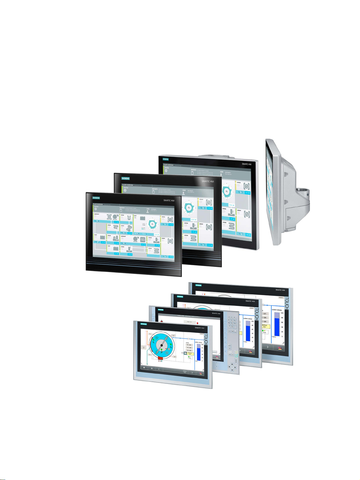
SIMATIC Industrial Flat Panels are LCD monitors suitable for industrial use with a brilliant
TFT display which can be connected to all SIMATIC IPCs as well as almost all generally
available PCs.
IFP, IFP PRO, IFP ETH
Operating Instructions, 11/2017, A5E31298376-AH
9

Overview
Features of the built-in units
Additional features of the Extended versions
1.1 Product description
● Rugged front
● Brilliant TFT display with a wide reading angle;
Resistive single touch screen in sizes 15", 19" and 22"
Capacitive multi-touch screen available in sizes 15", 19" and 22"
● Available as pure display device (monitor) or touch device
● Can be placed up to 5 m from the IPC
● DVI-D and DisplayPort V1.1 interface
● Multi-monitoring support
● Backlighting can be dimmed via software
● 24 V DC power supply
● Degree of protection IP65 in installed state
● Enclosure type: Front face only Type 4X/Type 12 (indoor use only)
● Up to 16 million colors
● Up to 30 m away from PC possible via DVI
● Power supply (with USB) 24 V DC and 100-240 V AC
● 2 USB ports
● Also available as touch/key version with front USB interface
IFP, IFP PRO, IFP ETH
10 Operating Instructions, 11/2017, A5E31298376-AH

Overview
Additional features of the PRO devices
Additional features of the Ethernet Monitors
1.1 Product description
● All-round dust-proof and splash-proof with IP65 degree of protection and Enclosure Type
4X / 12 (indoor use only)
● Can be mounted directly on the machine
● 19" display, 22" display; capacitive multi-touch screen
● Device versions for mounting:
– IFP PRO for pedestal (extendable, flange bottom)
– IFP PRO for support arm (not extendable, flange top)
– IFP PRO for support arm (extendable, round tube)
Adapters and adapter sets that can be ordered separately support mounting systems
from various manufacturers.
– Basic adapter, included in the product package of PRO devices for pedestal
(extendable, flange bottom) and for support arm (not extendable, flange top).
– With PRO devices for support arm (extendable, round tube):
- Cover for the mechanical interface below, included in the product package
- Flange mount available as accessory
● Can be placed up to 30 m away via DVI
● 2 USB ports
● Configuration and operation in the Ethernet/LAN network
● Length of the Ethernet/LAN connection as customary with conventional LAN technology
● Automatic establishment of connection to SIMATIC IPC
● Automatic configuration using 1:1 cable connection
● Ethernet Monitor software and monitor diagnostic function
IFP, IFP PRO, IFP ETH
Operating Instructions, 11/2017, A5E31298376-AH
11
Overview
1.2
Scope of delivery
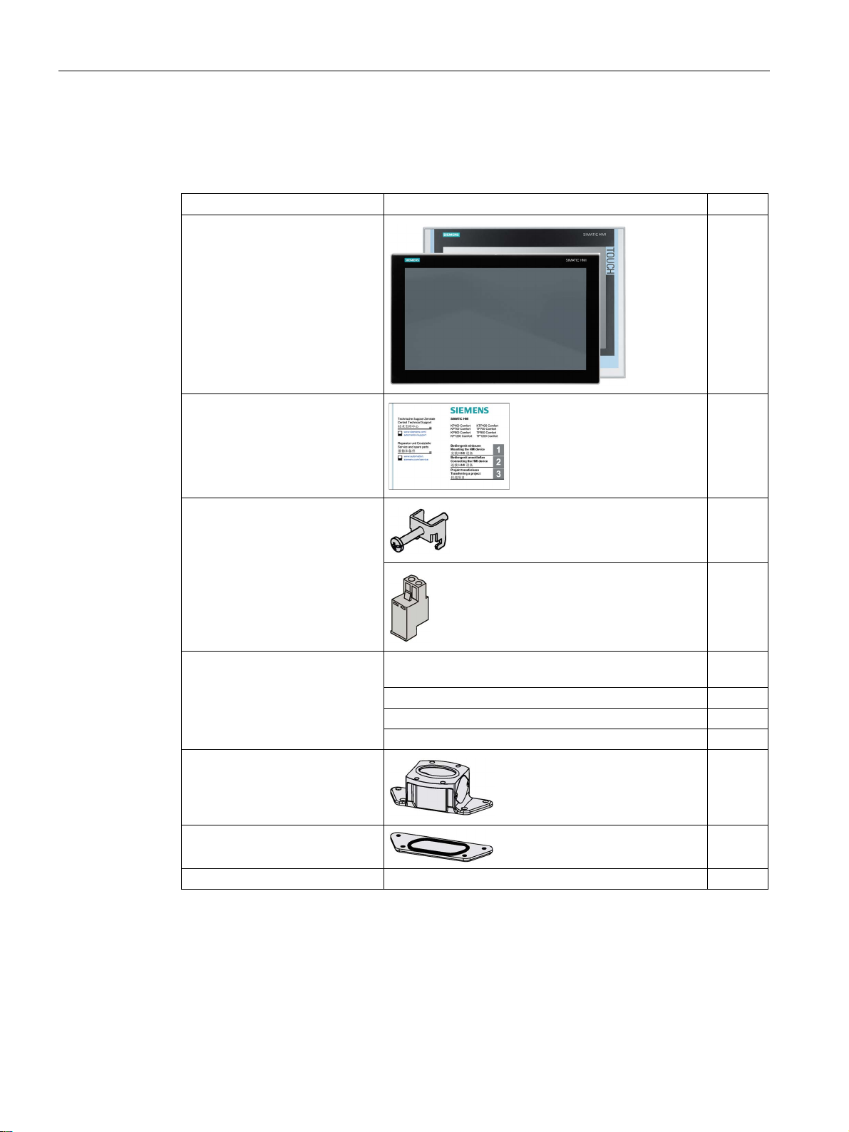
Name
Figure
Number
Accessory kit
12
2 m in length, for commissioning
USB connecting cable, 2 m in length2
1
Ethernet connecting cable, 2 m in length3
1
Power supply cable 230 V AC 4
1
"Documentation and Drivers" CD
1
1
2
3
4
5
6
Only with PRO devices for support arm (extendable, round tube)
1.2 Scope of delivery
The product package includes the following components:
Industrial Flat Panel
Installation instructions
(Quick Install Guide)
"Mounting clips 1
and
power supply connector"
1
1
1
IFP, IFP PRO, IFP ETH
12 Operating Instructions, 11/2017, A5E31298376-AH
"Connecting cables"
accessory kit
1
DVI connecting cable or DisplayPort connecting cable;
Base adapter 5
Cover for mechanical interface 6
Not with PRO devices
Not with standard display device (monitor)
Only with devices of the Ethernet Monitor type
Only with devices with AC power supply
Only with PRO devices for pedestal (extendable, flange bottom) and
for support arm (not extendable, flange top)
1
1
1
Overview
1.3
Design of the built-in units
1.3.1
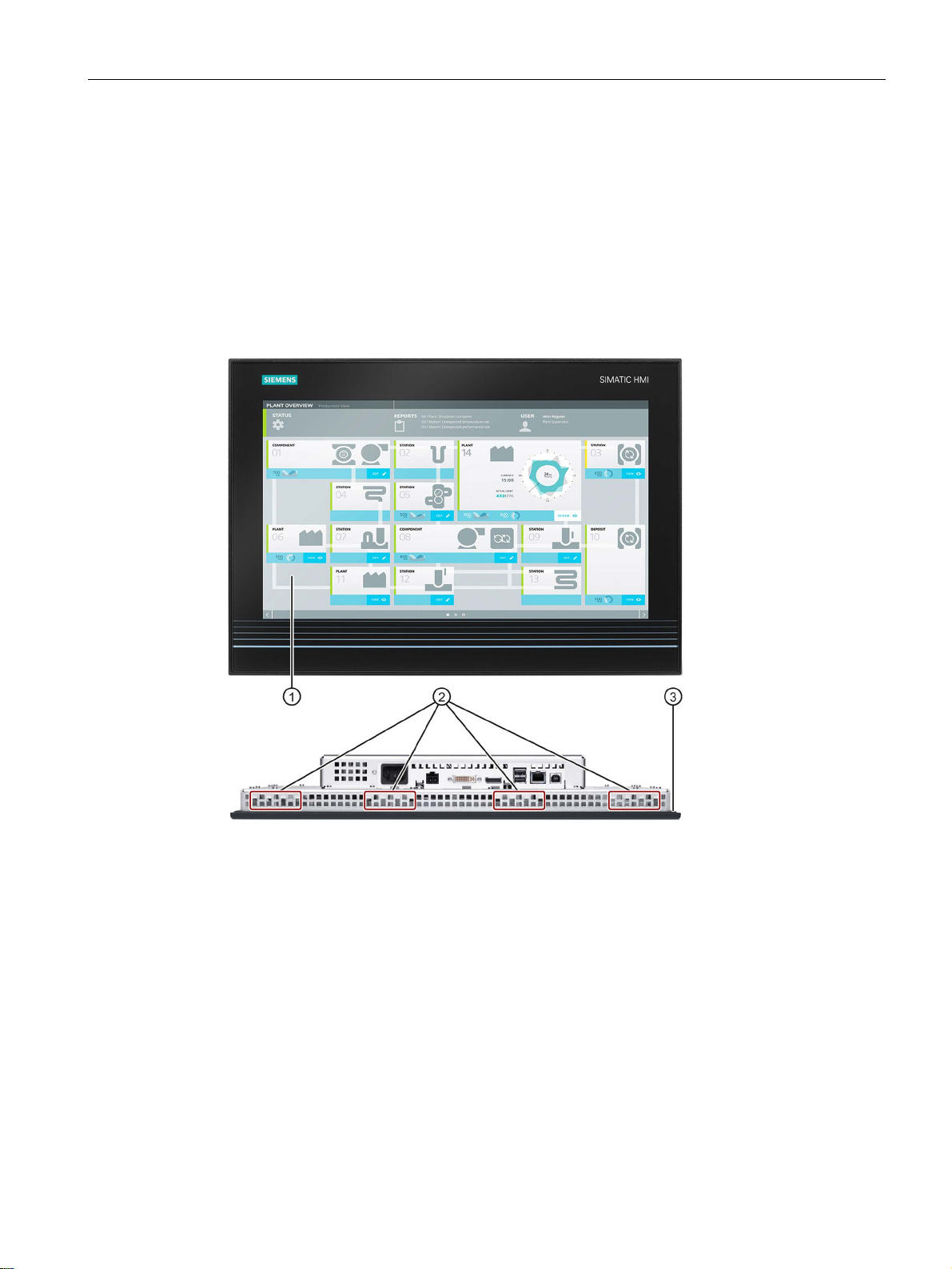
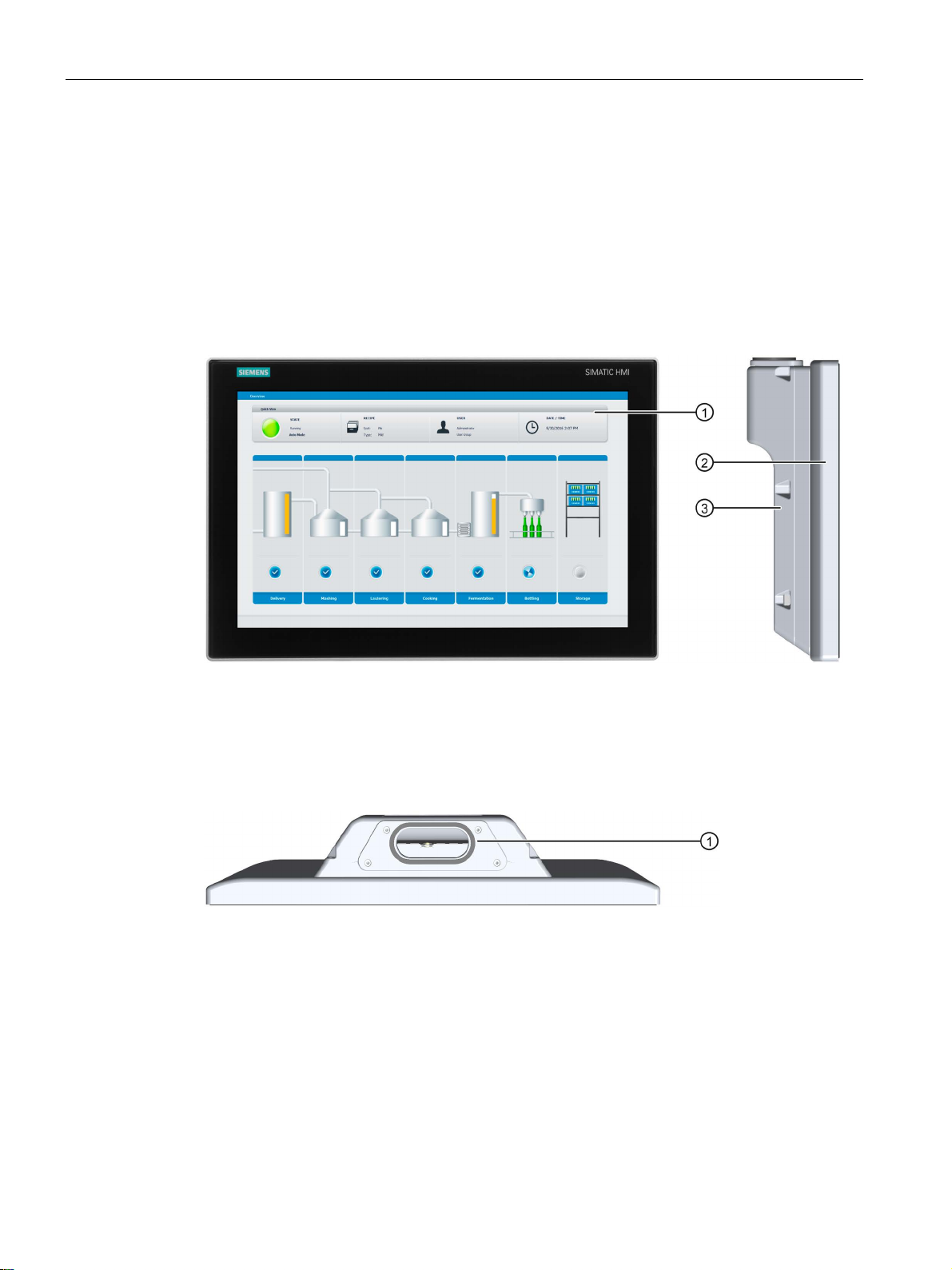
IFP1500/1900/2200 Multitouch, IFP1900/2200 ETH
Front view and bottom view
①
Display/touch screen
②
Recesses for mounting clips
③
Mounting seal
1.3 Design of the built-in units
This section describes the design of the multi-touch devices, using the IFP1900 Multitouch
as an example.
IFP, IFP PRO, IFP ETH
Operating Instructions, 11/2017, A5E31298376-AH
13
Overview
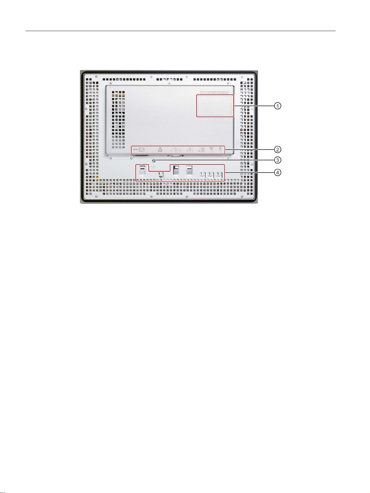
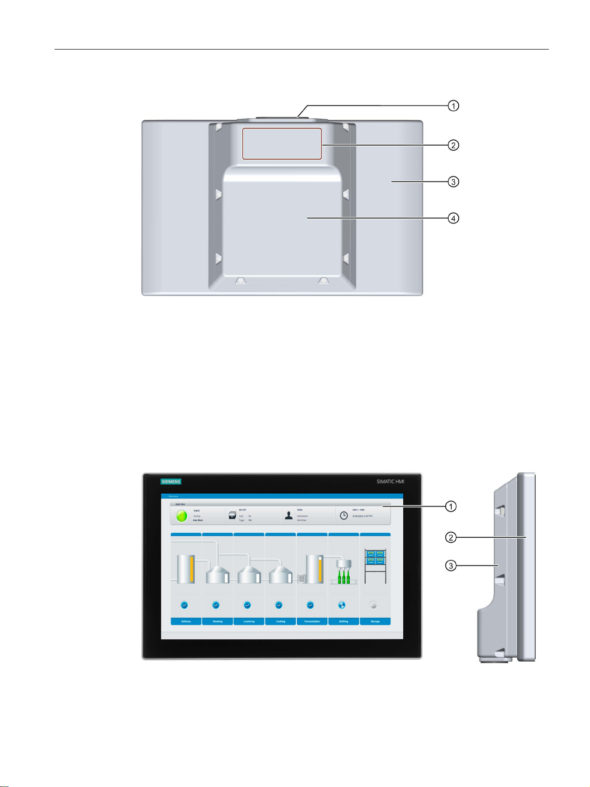
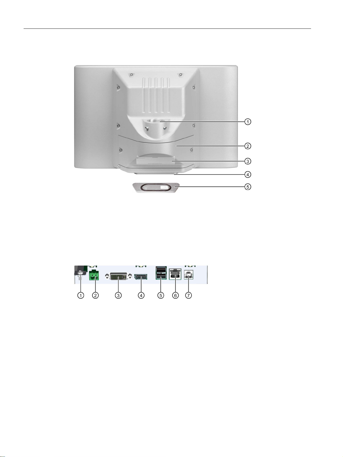
Rear view
①
Rating plate
②
Interface name
③
Equipotential bonding
④
Retaining elements for strain relief of the connecting cables
1.3 Design of the built-in units
IFP, IFP PRO, IFP ETH
14 Operating Instructions, 11/2017, A5E31298376-AH
Overview
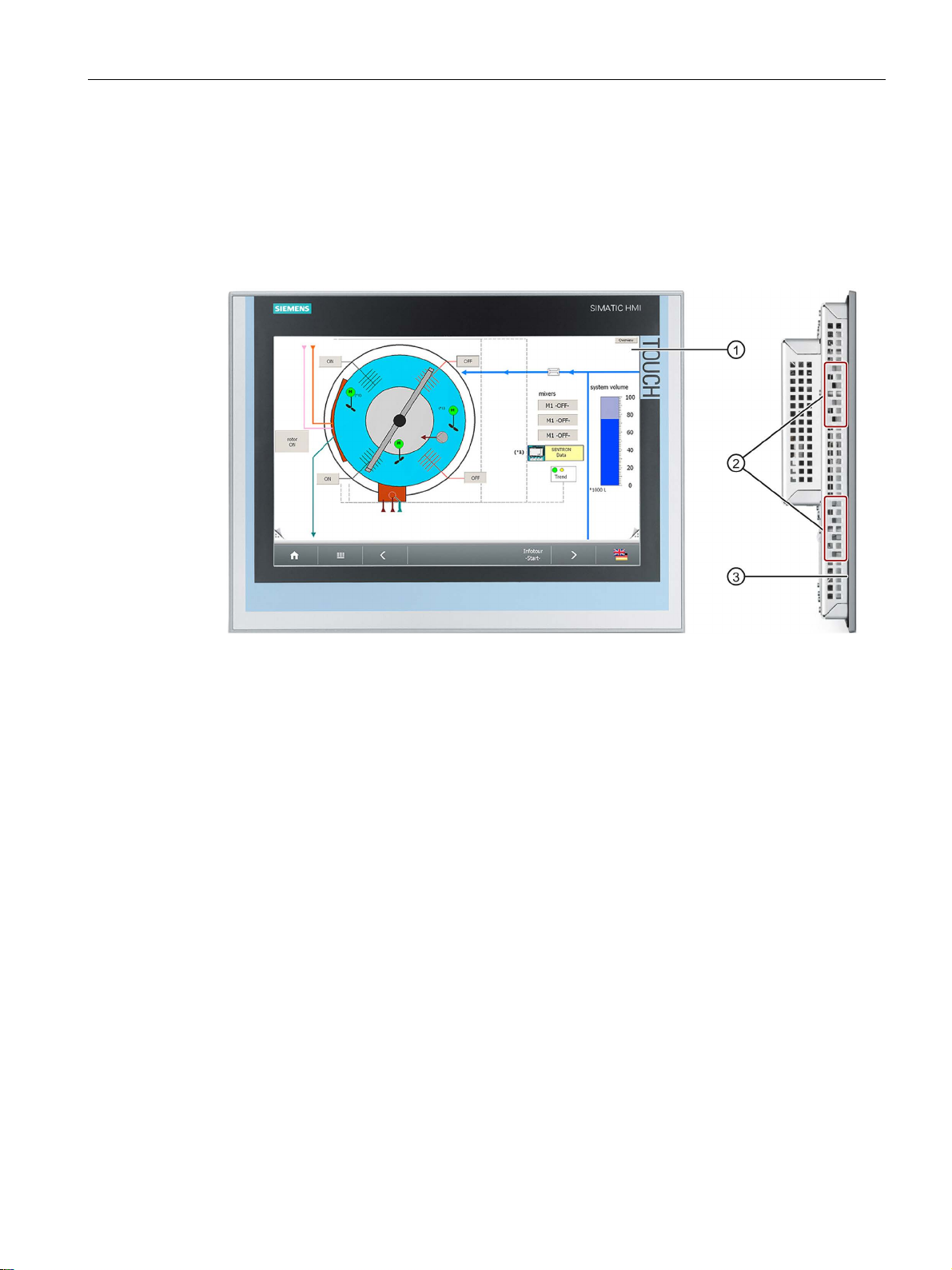
1.3.2
IFP1500/1900/2200 Touch
Front view and side view
①
Display/touch screen
②
Recesses for mounting clips
③
Mounting seal
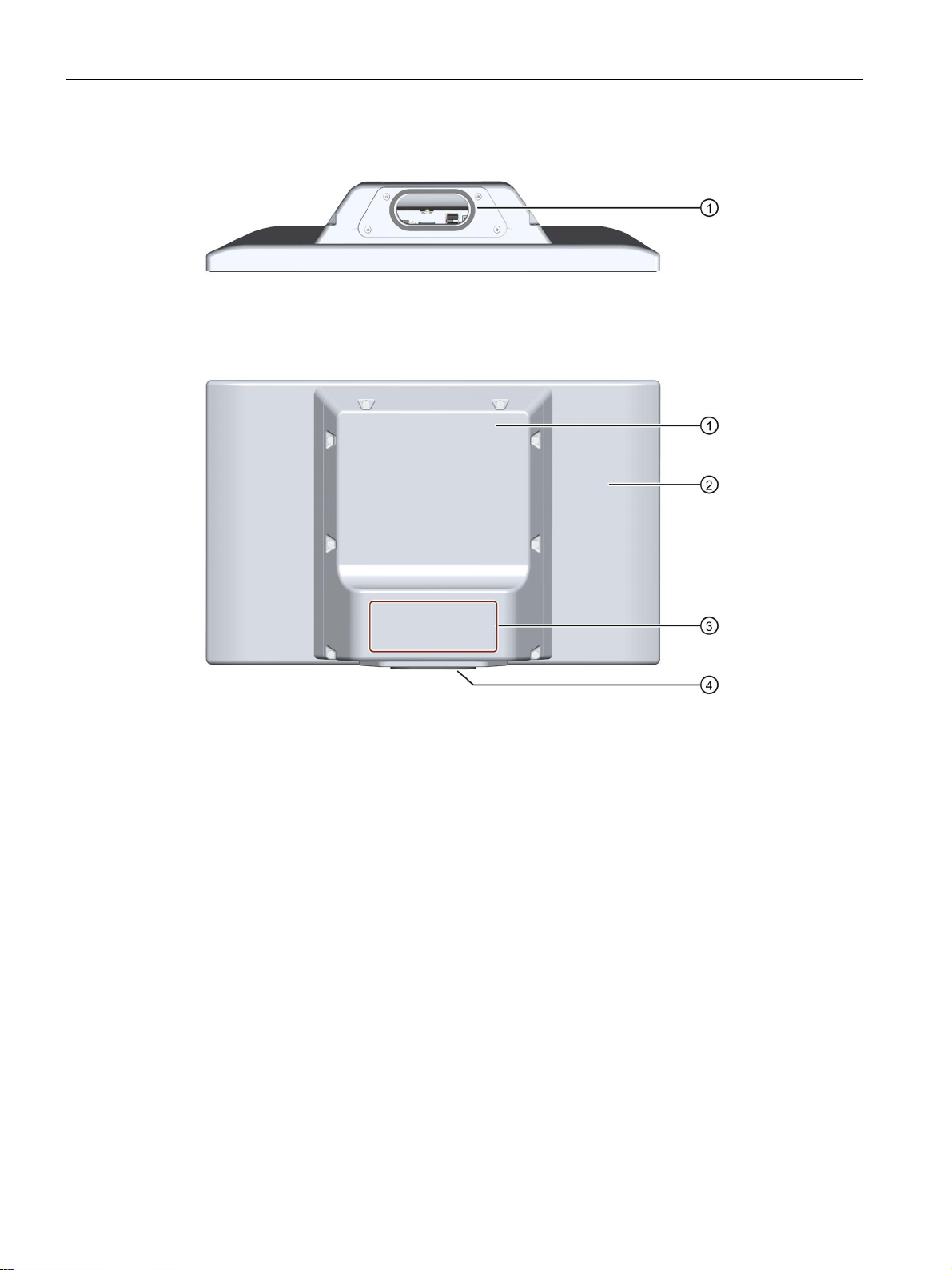
Rear view
1.3 Design of the built-in units
This section describes the design of the monitor and touch devices, using the IFP1500
Touch as an example.
See section "IFP1500/1900/2200 Multitouch".
IFP, IFP PRO, IFP ETH
Operating Instructions, 11/2017, A5E31298376-AH
15
Overview
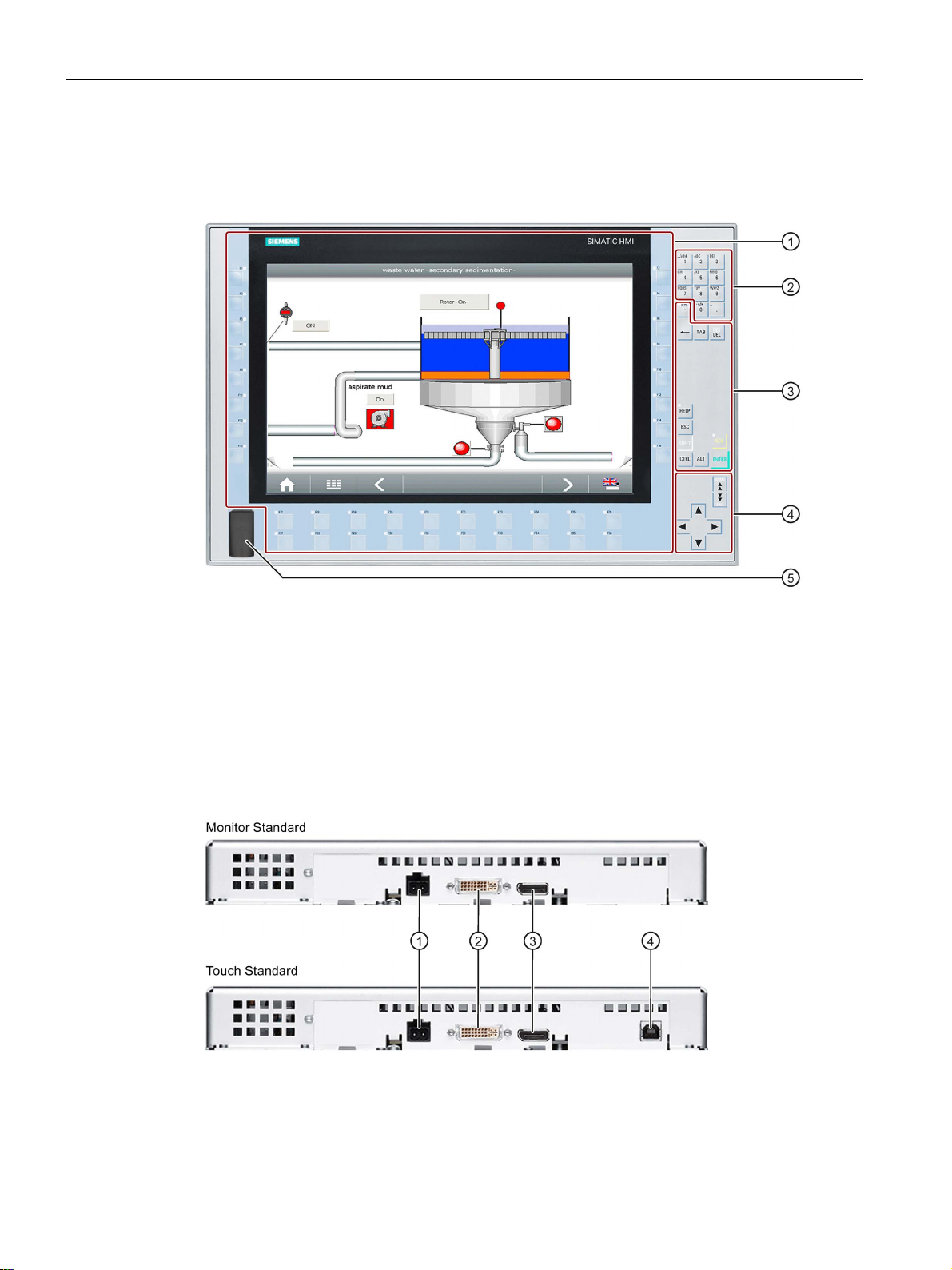
1.3.3
IFP1500 Touch/Key
Front view
①
Display and function keys with LED
②
Alphanumeric keys
③
Control keys
④
Cursor keys
⑤
USB port
1.3.4
Interfaces
1.3.4.1
Standard versions
①
X80 connector for 24 V DC power supply
②
X71 DVI-D interface
③
X70 DisplayPort interface
④
X60 USB Type B
1.3 Design of the built-in units
IFP, IFP PRO, IFP ETH
16 Operating Instructions, 11/2017, A5E31298376-AH
Overview
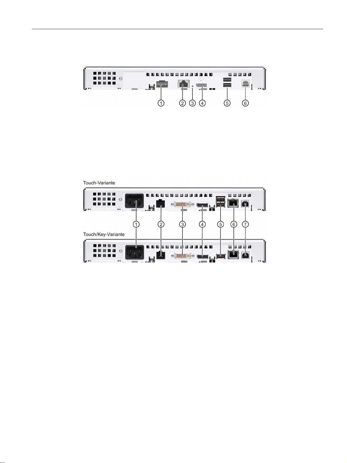
1.3.4.2
Ethernet Monitor devices
①
X80 connector for 24 V DC power supply
②
X1 Ethernet port
③
Reset button
④
X70 DisplayPort interface
⑤
X61/X62 USB Type A
⑥
X60 USB Type B
1.3.4.3
Extended versions
①
Connection for 100 to 240 V AC power supply
⑤
X61/X62 USB Type A
②
X80 connector for 24 V DC power supply
⑥
X63 USB link interface
③
X71 DVI-D interface
⑦
X60 USB Type B
④
X70 DisplayPort interface
1.3 Design of the built-in units
IFP, IFP PRO, IFP ETH
Operating Instructions, 11/2017, A5E31298376-AH
17
Overview
1.4
Design of the PRO devices
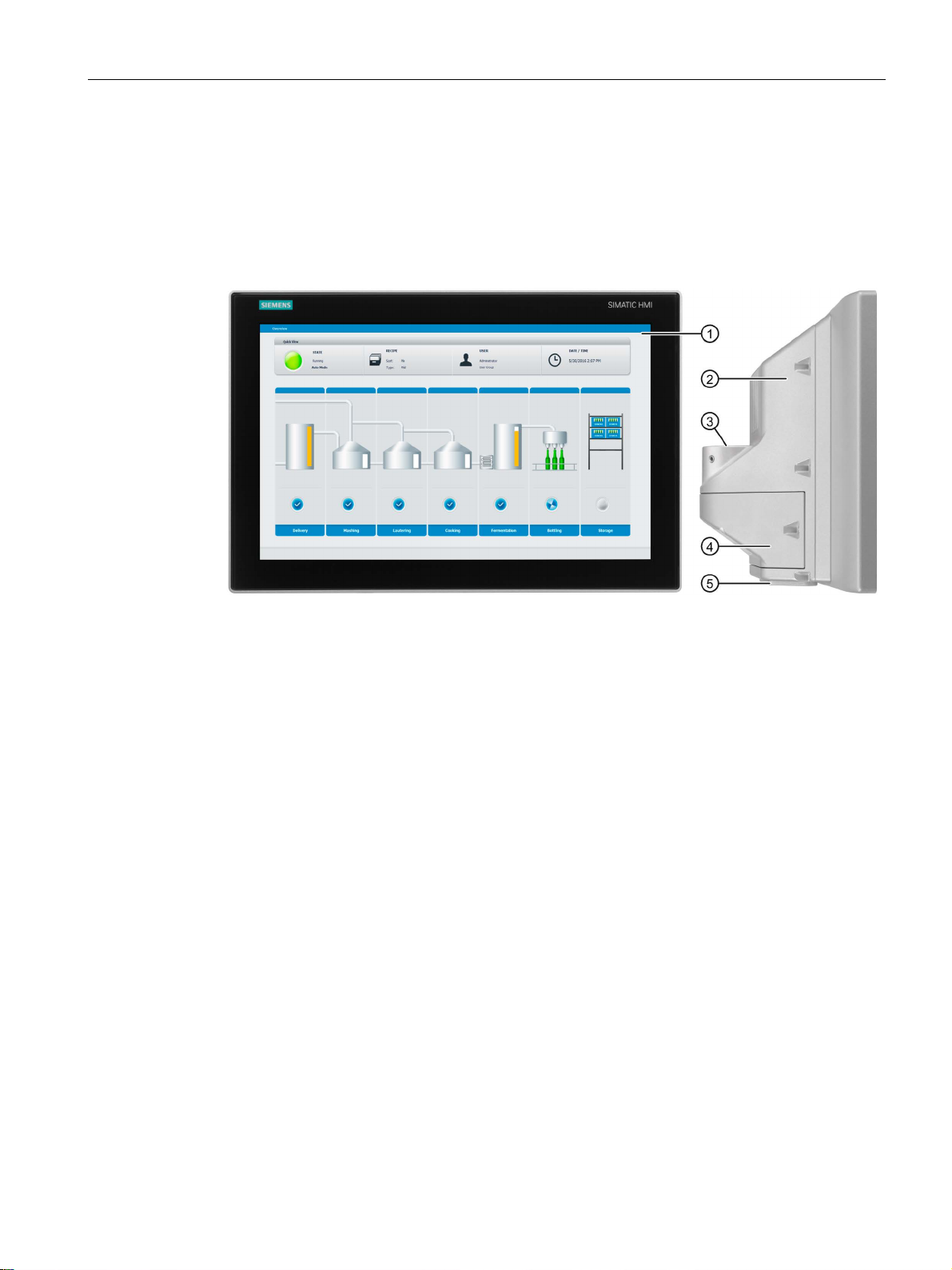
1.4.1
PRO devices for support arm (not extendable, flange top)
Front view and side view
①
Display with touch screen
②
Enclosure
③
Backplane cover
Top view
①
Mechanical interface for fastening
1.4 Design of the PRO devices
The following figures show the design of the devices using the IFP1900 PRO for support arm
(not extendable, flange top) as an example.
IFP, IFP PRO, IFP ETH
18 Operating Instructions, 11/2017, A5E31298376-AH
Overview
Rear view
①
Mechanical interface for fastening
②
Rating plate
③
Enclosure
④
Backplane cover
1.4.2
PRO devices for pedestal (extendable, flange bottom)
Front view and side view
①
Display with touch screen
②
Enclosure
③
Backplane cover
1.4 Design of the PRO devices
The following figures show the design of the devices using the IFP1900 PRO for pedestal
(extendable, flange bottom) as an example.
IFP, IFP PRO, IFP ETH
Operating Instructions, 11/2017, A5E31298376-AH
19
Overview
Bottom view
①
Mechanical interface for fastening
Rear view
①
Backplane cover
②
Enclosure
③
Rating plate
④
Mechanical interface for fastening
1.4 Design of the PRO devices
IFP, IFP PRO, IFP ETH
20 Operating Instructions, 11/2017, A5E31298376-AH
Overview
1.4.3
PRO devices for support arm (extendable, round tube)
Front view and side view
①
Display with touch screen
②
Enclosure
③
Mechanical interface for fastening (round tube)
④
Terminal compartment cover
⑤
Mechanical interface below
1.4 Design of the PRO devices
The following figures show the design of the devices using IFP1900 PRO for support arm
(extendable, round tube) as an example.
IFP, IFP PRO, IFP ETH
Operating Instructions, 11/2017, A5E31298376-AH
21
Overview
Rear view
①
Mechanical interface for fastening (round tube)
②
Terminal compartment cover
③
Nameplate
④
Mechanical interface below
⑤
Lower cover, included in the product package
1.4.4
Interfaces
①
Protective conductor terminal
⑤
X61/X62 USB Type A
②
ply
⑥
③
X71 DVI-D interface
⑦
X60 USB Type B
④
X70 DisplayPort interface
1.4 Design of the PRO devices
X80 connector for 24 V DC power sup-
X63 USB link interface
IFP, IFP PRO, IFP ETH
22 Operating Instructions, 11/2017, A5E31298376-AH
Overview
1.5
System components and accessories
System components
Accessories
1.5.1
System components for PRO devices
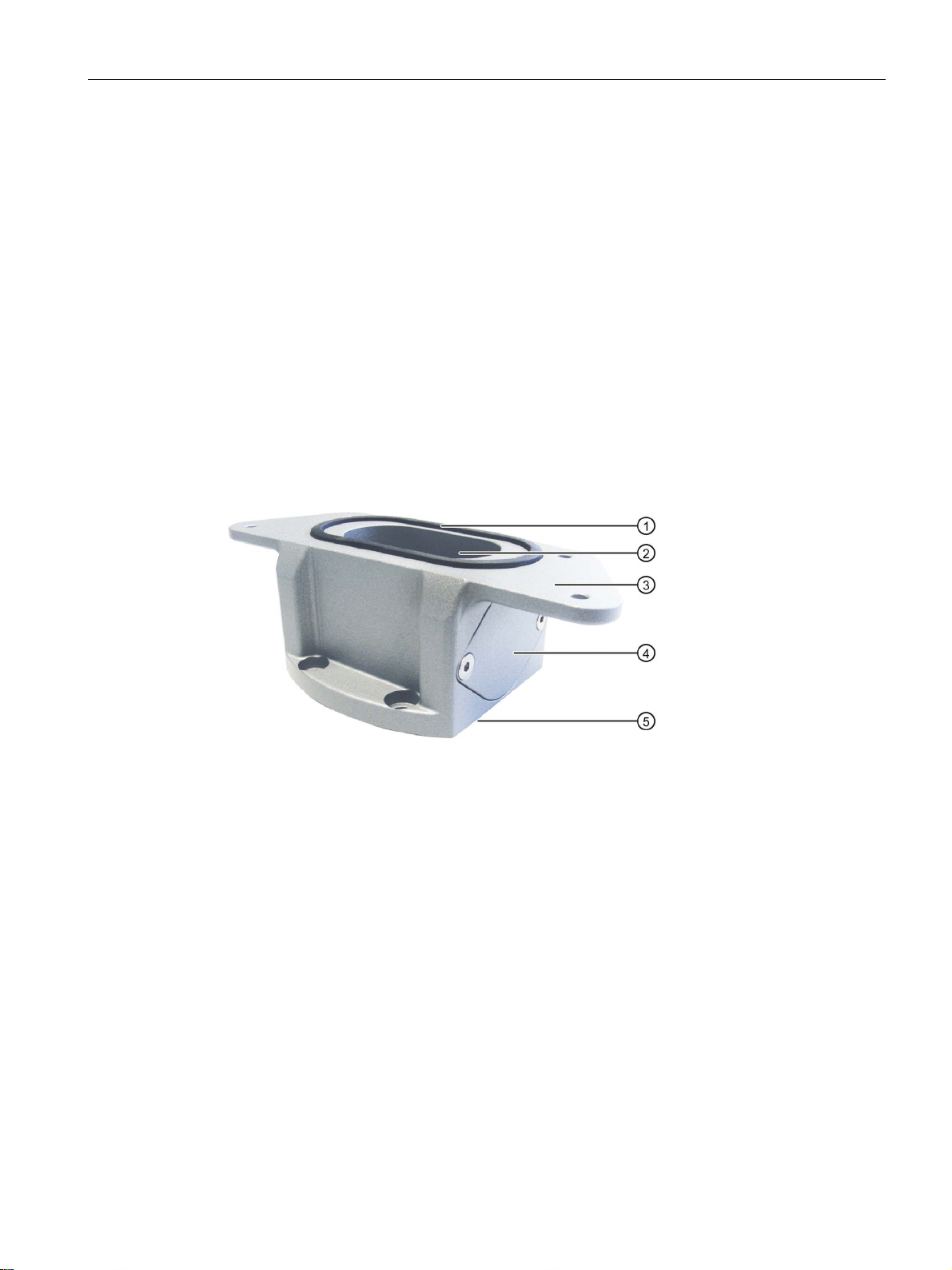
Base adapter
①
Seal
②
Channel cable
③
Mechanical interface to the PRO device
④
Cover
⑤
Mechanical interface to the support arm or pedestal including seal
1.5 System components and accessories
not be used in general, for example, like the base adapter. System components are always
directly related to a core product.
families, for example, batteries, touch pens or protective membranes.
can typically be used for multiple devices from the same or different device
are products that have been developed for a specific system and can
You use the base adapter to mount PRO devices for support arm (not extendable,
flange top) or for pedestal (extendable, flange bottom) on the support arm or on the pedestal.
A base adapter is included with the product package of the corresponding PRO device. The
base adapter can also be ordered separately.
Article number: 6AV7674-1KA00-0AA0
IFP, IFP PRO, IFP ETH
Operating Instructions, 11/2017, A5E31298376-AH
23

Overview
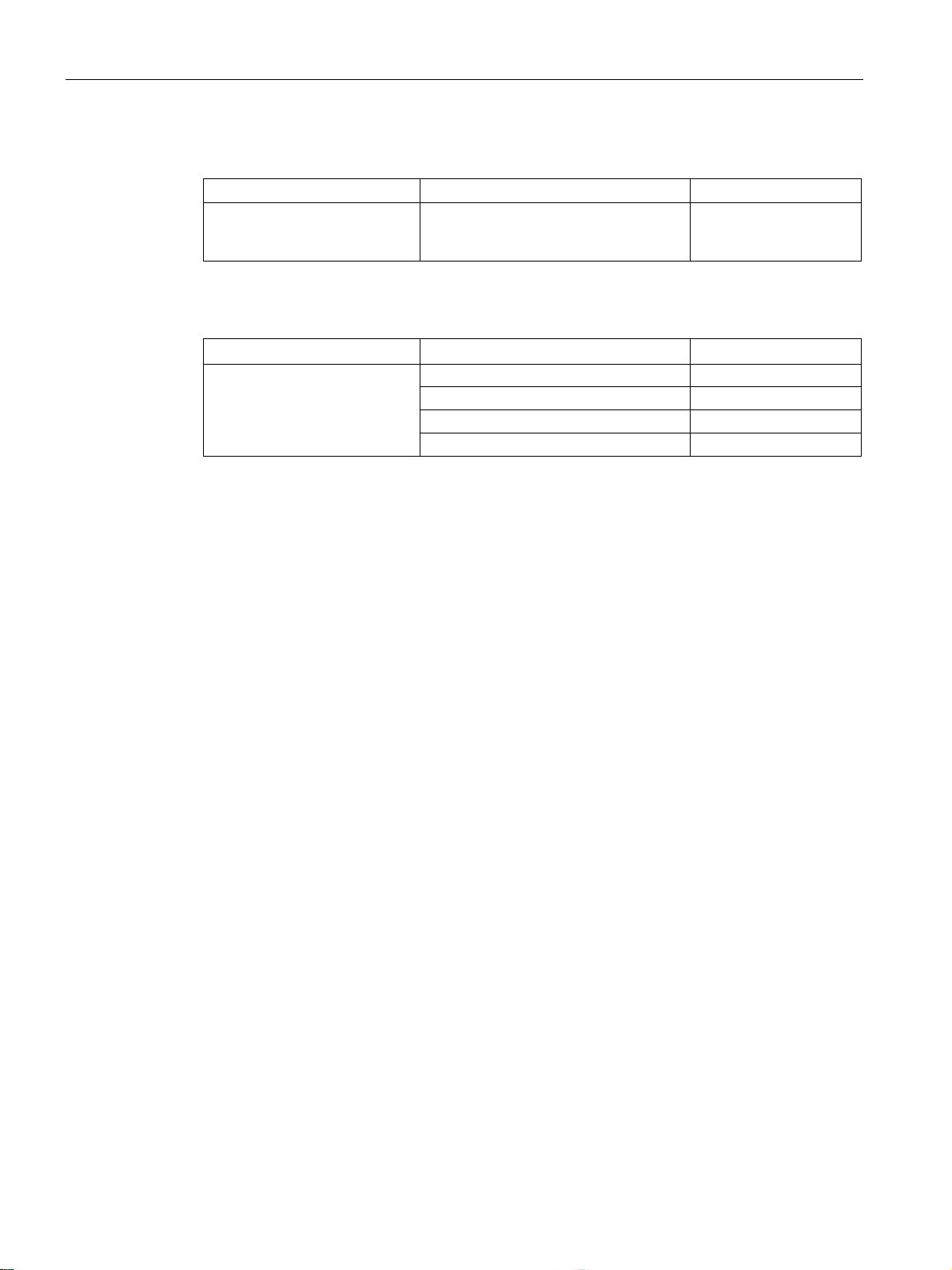
Adapter sets and couplings
Adapter version
Suitable for supporting arm systems
Article number
SIEMENS
RITTAL
ROLEC
BERNSTEIN
All information subject to change.
1.5 System components and accessories
The following mechanical adapter versions are also available for mounting a PRO device
for support arm (not extendable, flange top) or for pedestal (extendable, flange bottom) via
the base adapter:
● A Siemens VESA adapter set for VESA compatible systems
● Manufacturer-specific adapters or couplings
The following table shows the available Siemens adapter sets and examples of vendorspecific adapter versions:
• Adapter set VESA75
• Adapter set VESA100
Adapter for Siemens PRO
Panel
• Intermediate plate
• Screws
Adapter for Siemens PRO
Panel
• Intermediate plate
• Screws
Coupling for Siemens
SIMATIC PRO
• No intermediate plate re-
quired
• Coupling with integrated
adaptation for PRO devices
VESA75-compatible systems 6AV7674-0KE00-0AA0
VESA100-compatible systems 6AV7674-0KD00-0AA0
• CP40 steel
• CP60/120 for
support arm connection
120 × 65 mm
• profiPlus-50
• taraPLUS for ∅ 65 mm hole circle
• CS-3000 • 1015300187 RAL 9006
6206.500
142.024.000
White aluminum
• 1015300043 RAL 7016
Anthracite grey
IFP, IFP PRO, IFP ETH
24 Operating Instructions, 11/2017, A5E31298376-AH
Overview
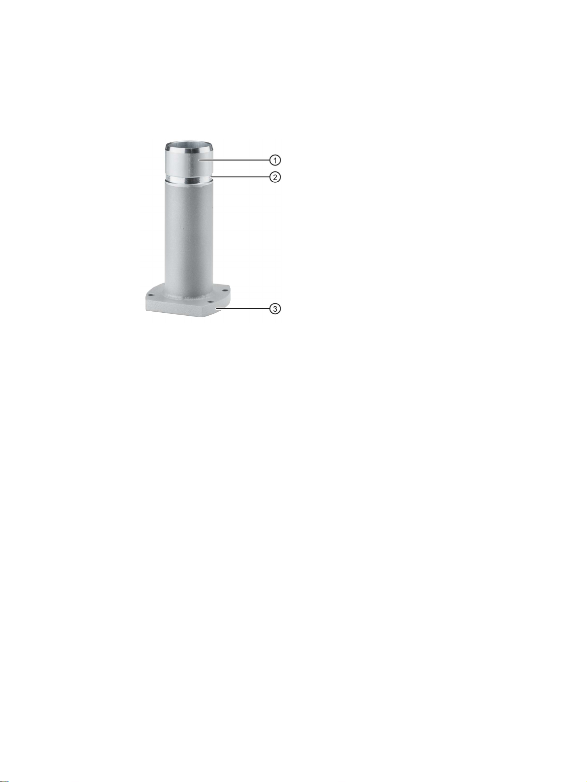
Flange mount adapter
①
Flange mount adapter
②
Ring groove for fastening on PRO device with setscrews
③
Mechanical interface to support arm
1.5 System components and accessories
A flange mount adapter is available for mounting a PRO device for support arm (extendable,
round tube).
Article number: 6AV7674-1KF00-0AA0
IFP, IFP PRO, IFP ETH
Operating Instructions, 11/2017, A5E31298376-AH
25

Overview
Extension components - Extension Unit
Note
Only operator controls with Siemens approval may be installed in the Extension Unit.
Additional information
1.5 System components and accessories
The Extension Unit is used to install additional operator controls below a SIMATIC PRO
device for pedestal (extendable, flange bottom) or for support arm (extendable, round tube).
By way of example, the figure below shows the Extension Unit 22" with eight operator
controls including Emergency Stop button.
The operator controls on the Extension Units can be customized. The Extension Units come
without operator controls. The possible mounting spaces are prepared for installation of
operator controls.
The Extension Units are available in four sizes:
● Extension Unit 12"
● Extension Unit 15"
● Extension Unit 19"
● Extension Unit 22"
In each Extension Unit size, you have the flexibility to choose between the following interface
variants for connection to the system:
● Hardwired
● PROFINET
● PROFIsafe
In addition, different operator controls, such as Emergency Stop pushbutton, selector switch,
illuminated pushbutton, keyswitch, indicator light and RFID reader, are available.
You can find additional information on system components for full-enclosed IP65-protected
devices on the Internet
(https://mall.industry.siemens.com/mall/en/WW/Catalog/Products/10268745
IFP, IFP PRO, IFP ETH
26 Operating Instructions, 11/2017, A5E31298376-AH
).
Overview
1.5.2
Accessories
Introduction
All Industrial Flat Panels
Name
Specification
Article number
3 m long
6AV7860-0BH30-0AA0
5 m long
6AV7860-0BH50-0AA0
3 m long
6AV7860-0DH30-0AA0
5 m long
6AV7860-0DH50-0AA0
3 m long
6AV7860-0CH30-0AA0
15"
6AV2124-6QJ00-0AX0
19"
6AV2124-6UJ00-0AX0
22"
6AV2124-6XJ00-0AX0
For resistive touch screen
6AV7672-1JB00-0AA0
Built-in units
Name
Specification
Article number
Mounting clips service pack
20 pieces
6AV6671-8XK00-0AX3
Mounting brackets service pack
2 x 8 latch fasteners
6AV7672-1JC00-0AA0
Extended version
Name
Specification
Article number
10 m long
6AV7860-1EX21-0AA1
20 m long
6AV7860-1EX22-0AA1
30 m long
6AV7860-1EX23-0AA1
1.5 System components and accessories
This section contains the number of accessories available at the time of publication of the
operating instructions. You will find additional accessories on the Internet at:
● Industry Mall (https://mall.industry.siemens.com)
● Expansion components and accessories (http://www.automation.siemens.com/mcms/pc-
based-automation/en/industrial-pc/expansion_components_accessories)
● Ethernet cable accessories
(https://support.industry.siemens.com/cs/ww/en/view/98278804
DVI line
)
DisplayPort line
USB line
Protective foil for the touch
screen
Touch pen
5 m long 6AV7860-0CH50-0AA0
For capacitive and resistive touch
screen
6AV2181-8AV20-0AX0
IFP, IFP PRO, IFP ETH
Operating Instructions, 11/2017, A5E31298376-AH
Cable set (DVI/USB cable)
15 m long 6AV7860-1EX21-5AA1
27
Overview
Touch/Key Extended version
Name
Article number
Drivers" CD/DVD.
Ethernet Monitors
Name
Specification
Article number
TP Cord RJ45/RJ45, 20 m
6XV1870-3QN20
TP Cord RJ45/RJ45, 50 m
6XV1870-3QN50
1.5 System components and accessories
Film for labeling the function
keys (slide-in labels)
Recommended Ethernet RJ45
cables (selection)
Print templates for the slide-in labels are
available on the "Documentation and
TP Cord RJ45/RJ45, 15 m 6XV1870-3QN15
TP Cord RJ45/RJ45, 30 m 6XV1870-3QN30
6AV7672-0DA00-0AA0
Additional Ethernet cables: See link "Accessories Ethernet cables" at the beginning of this
section.
IFP, IFP PRO, IFP ETH
28 Operating Instructions, 11/2017, A5E31298376-AH
2
2.1
General safety instructions
Machinery Directive
WARNING
The device may only be used in machines which comply with the Machinery Directive
Strong high-frequency radiation
NOTICE
Observe immunity to high-frequency radiation
The device is designed for use in the industrial sector for operating and monitoring plant
processes.
The Machinery Directive specifies precautions to be taken when commissioning and
operating machinery within the European Economic Area.
Failure to follow these precautions is a breach of the Machinery Directive. Such failure may
also cause personal injury and damage depending on the machine operated.
The machine in which the HMI device is to be operated must conform to Directive
2006/42/EC.
Observe the safety and accident prevention instructions applicable to your application in
addition to the safety information given in the device documentation.
The device has an increased immunity to high frequency radiation according to the
specifications on electromagnetic compatibility in the technical specifications.
Radiation exposure in excess of the specified immunity limits can impair device functions
and result in malfunctions and therefore injuries or damage.
Read the information on immunity to high frequency radiation in the technical specifications.
IFP, IFP PRO, IFP ETH
Operating Instructions, 11/2017, A5E31298376-AH
29
Safety information
Additional notes for built-in units
WARNING
The rear of the device constitutes open equipment.
Electrocution risk when control cabinet is open
not
ESD
Industrial Security
2.1 General safety instructions
The rear of the device constitutes open equipment. This means that the device may only be
installed in an enclosure or cabinet which provides front access for operating the device.
The enclosure, the cabinet or the electrical operating rooms must provide protection against
electric shock and the spread of fire. The requirements regarding the mechanical strength
must also be taken into account.
Access to the enclosure or cabinet in which the device is installed should only be possible
by means of a key or tool and for trained and authorized personnel.
When you open the control cabinet, there may be a dangerous voltage at certain areas or
components.
If you touch these areas or components, you may be killed by electric shock.
Always disconnect the control cabinet from the mains before opening it. Do
pull out the system component during operation.
An electrostatically sensitive device is equipped with electronic components. Due to their
design, electronic components are sensitive to overvoltage and thus to the discharge of
static electricity. Note the corresponding regulations when handling ESD.
Siemens provides products and solutions with industrial security functions that support the
secure operation of plants, systems, machines and networks.
In order to protect plants, systems, machines and networks against cyber threats, it is
necessary to implement – and continuously maintain – a holistic, state-of-the-art industrial
security concept. Siemens’ products and solutions constitute one element of such a concept.
Customers are responsible for preventing unauthorized access to their plants, systems,
machines and networks. Such systems, machines and components should only be
connected to an enterprise network or the internet if and to the extent such a connection is
necessary and only when appropriate security measures (e.g. use of firewalls and network
segmentation) are in place.
For additional information on industrial security measures that may be implemented,please
visit (http://www.siemens.com/industrialsecurity
plug in or
).
Siemens’ products and solutions undergo continuous development to make them more
secure. Siemens strongly recommends that product updates are applied as soon as they are
available and that the latest product versions are used. Use of product versions that are no
longer supported, and failure to apply latest updates may increase customer’s exposure to
cyber threats.
To stay informed about product updates, subscribe to the Siemens Industrial Security RSS
IFP, IFP PRO, IFP ETH
Feed under (http://www.siemens.com/industrialsecurity
30 Operating Instructions, 11/2017, A5E31298376-AH
).
 Loading...