

Siemens SIMATIC Ident, SIMATIC RF-DIAG Operating Manual

SIMATIC RF-DIAG
_
_________________
_
_
_________________
_
_
_________________
_
_
_________________
_
_
_________________
_
_
_________________
_
_
_________________
_
_
_________________
_
RFID systems
SIMATIC Ident
SIMATIC RF-DIAG
Operating Manual
09/2012
C79000-G8976-C292-01
Introduction
1
Description
2
Connecting hardware
3
Software installation
4
Operating the software
5
Application Examples
6
Error and system messages
7
Appendix A
A
Siemens AG
Industry Sector
Postfach 48 48
90026 NÜRNBERG
GERMANY
Order number: C79000-G8976-C292
Ⓟ 09/2012 Technical data subject to change
Copyright © Siemens AG 2012.
All rights reserved
Legal information
Warning notice system
This manual contains notices you have to observe in order to ensure your personal safety, as well as to prevent
damage to property. The notices referring to your personal safety are highlighted in the manual by a safety alert
symbol, notices referring only to property damage have no safety alert symbol. These notices shown below are
graded according to the degree of danger.
DANGER
indicates that death or severe personal injury will result if proper precautions are not taken.
WARNING
indicates that death or severe personal injury may result if proper precautions are not taken.
CAUTION
indicates that minor personal injury can result if proper precautions are not taken.
NOTICE
indicates that property damage can result if proper precautions are not taken.
If more than one degree of danger is present, the warning notice representing the highest degree of danger will
be used. A notice warning of injury to persons with a safety alert symbol may also include a warning relating to
property damage.
Qualified Personnel
The product/system described in this documentation may be operated only by personnel qualified for the specific
task in accordance with the relevant documentation, in particular its warning notices and safety instructions.
Qualified personnel are those who, based on their training and experience, are capable of identifying risks and
avoiding potential hazards when working with these products/systems.
Proper use of Siemens products
Note the following:
WARNING
Siemens products may only be used for the applications described in the catalog and in the relevant technical
documentation. If products and components from other manufacturers are used, these must be recommended
or approved by Siemens. Proper transport, storage, installation, assembly, commissioning, operation and
maintenance are required to ensure that the products operate safely and without any problems. The permissible
ambient conditions must be complied with. The information in the relevant documentation must be observed.
Trademarks
All names identified by ® are registered trademarks of Siemens AG. The remaining trademarks in this publication
may be trademarks whose use by third parties for their own purposes could violate the rights of the owner.
Disclaimer of Liability
We have reviewed the contents of this publication to ensure consistency with the hardware and software
described. Since variance cannot be precluded entirely, we cannot guarantee full consistency. However, the
information in this publication is reviewed regularly and any necessary corrections are included in subsequent
editions.

SIMATIC RF-DIAG
Operating Manual, 09/2012, C79000-G8976-C292-01
3
Table of contents
1 Introduction................................................................................................................................................ 5
1.1
Preliminary information ..................................................................................................................5
1.2
Abbreviations and naming conventions .........................................................................................6
2
Description................................................................................................................................................. 7
2.1
Requirements and notices .............................................................................................................7
2.2
Area of application and scenarios..................................................................................................8
2.3
Components of the product and ordering data ..............................................................................9
3
Connecting hardware............................................................................................................................... 11
3.1
The PC adapter for SIMATIC RF-DIAG.......................................................................................12
3.1.1
Description ...................................................................................................................................12
3.1.2
Pin assignment of the RS-422 interface ......................................................................................13
3.1.3
Technical specifications ...............................................................................................................16
3.1.4
Dimension drawing ......................................................................................................................18
3.1.5
Certificates and approvals ...........................................................................................................19
3.2
Connecting the hardware.............................................................................................................19
3.2.1
Connecting an Ethernet-based reader.........................................................................................19
3.2.2
Connecting a serial reader...........................................................................................................21
4
Software installation................................................................................................................................. 23
4.1
Installing the software ..................................................................................................................23
4.2
Installation and use of the USB driver .........................................................................................23
4.3
Starting the software ....................................................................................................................25
5
Operating the software ............................................................................................................................ 29
5.1
The log area.................................................................................................................................30
5.2
Tab overview................................................................................................................................31
5.3
The tabs of the RF640R/RF670R readers...................................................................................32
5.3.1
The "Info" tab ...............................................................................................................................32
5.3.2
The "Tag Data" tab.......................................................................................................................34
5.3.3
The "IO" tab..................................................................................................................................36
5.3.4
The "RSSI" tab.............................................................................................................................38
5.3.5
The "Tag Events" tab ...................................................................................................................41
5.4
The tabs of the RF620R/RF630R readers...................................................................................43
5.4.1
The "Info" tab ...............................................................................................................................43
5.4.2
The "Tag Data" tab.......................................................................................................................45
5.4.3
The "RSSI" tab.............................................................................................................................48
5.4.4
The "Power Ramp" tab ................................................................................................................51
5.4.5
The "Tag List" tab.........................................................................................................................55
5.4.6
The "Parameters" tab...................................................................................................................58

Table of contents
SIMATIC RF-DIAG
4 Operating Manual, 09/2012, C79000-G8976-C292-01
5.4.7 The "VSWR" tab.......................................................................................................................... 62
5.4.8 The "Firmware-Update" tab......................................................................................................... 64
6
Application Examples .............................................................................................................................. 65
6.1
Scenarios for use of the PC adapter for RF-DIAG...................................................................... 65
6.2
Example of an application "optimize antenna position" .............................................................. 67
6.3
Example of an application "Determining transmit power"........................................................... 69
6.4
Example of an application "Setting the Power Ramp and RSSI Threshold" .............................. 71
6.5
Example of an application "Testing and setting parameters for industrial UHF algorithms" ...... 74
7
Error and system messages.................................................................................................................... 77
A
Appendix A .............................................................................................................................................. 79
A.1
Service & Support ....................................................................................................................... 79

SIMATIC RF-DIAG
Operating Manual, 09/2012, C79000-G8976-C292-01
5
Introduction
1
1.1 Preliminary information
Purpose of this document
This manual contains information on the installation and operation of the SIMATIC RF-DIAG
diagnostics tool. The diagnostics tool supports you during commissioning and diagnostics of
UHF reading points and helps you to optimize the reader settings.
It is intended for machine operators, production line operators, configuration engineers and
maintenance and servicing staff who are responsible for the smooth operation of the system.
To work with the diagnostics tool, you require knowledge of the Windows version you are
using, Windows XP or Windows 7.
To configure the RFID components, you require knowledge of the following:
● Structure of the particular plant
● Configuration of the plant
● Basic knowledge of RFID and UHF
Only perform the installation and subsequent configuration if you have this knowledge.
Registered trademarks
SIMATIC ® is a registered trademark of the Siemens AG.
History
The following edition(s) of this manual have been published previously:
Edition Note
09/2012 First edition
Additional documentation
You will find additional information on setting parameters for the RF620R/RF630R readers in
"Parameter assignment manual RF620R/RF620R
(http://support.automation.siemens.
com/WW/view/en/33287195)".
You will find additional information on setting parameters for the RF640R/RF670R readers in
the manuals"RF-MANAGER Basic" and "XML Programming".
You will find further information on the RF600 readers, antennas and accessories in the
"RF600 system manual (http://support.automation.siemens.
com/WW/view/en/22437600)".

Introduction
1.2 Abbreviations and naming conventions
SIMATIC RF-DIAG
6 Operating Manual, 09/2012, C79000-G8976-C292-01
1.2 Abbreviations and naming conventions
The following terms/abbreviations are used synonymously in this document:
Read/write device, RWD Reader
Mobile data storage, MDS, data carrier Transponder, tag
Interface module, IM Communications module, CM

SIMATIC RF-DIAG
Operating Manual, 09/2012, C79000-G8976-C292-01
7
Description
2
2.1 Requirements and notices
Minimum requirements
Table 2- 1 Hardware requirements
Processor > 1 GHz
Main memory > 1 GB RAM
Memory space ≥ 50 MB
Graphics resolution
• Minimum: 1024 × 786
• Recommended: 1280 × 1024
Additional hardware CD-ROM drive
Table 2- 2 Software requirements
Operating system
• Windows XP Professional, SP3 or higher
• Windows 7 Professional 32-bit, SP1 or higher
• Windows 7 Professional 64-bit, SP1 or higher
Additional software Microsoft .NET-Framework 2.01
Additional USB drivers2 Silicon Labs CP210x USB to UART Bridge3
1
The installation file for Microsoft .NET-Framework 2.0 is on the CD in the folder "DotNet
Framework 2.0".
2
Is required for communication with the RF620R/RF630R readers via the PC adapter for
SIMATIC RF-DIAG
3
The installation file for the USB driver is on the CD in the folder "Silabs"
Note
No multiple instance capability
The diagnostics tool cannot be opened and operated more than once at any one time.

Description
2.2 Area of application and scenarios
SIMATIC RF-DIAG
8 Operating Manual, 09/2012, C79000-G8976-C292-01
2.2 Area of application and scenarios
Where the diagnostics tool is used
The SIMATIC RF-DIAG diagnostics tool supports diagnostics of the following RF600
readers:
● Ethernet-based readers RF640R/RF670R
● Serial RF620R/RF630R readers
(In conjunction with the PC adapter that ships with the product)
Note
Parameter assignment of the RF640R/RF670R
To assign parameters to the RF640R and RF670R readers, you require the RF-MANAGER
Basic.
Note
Functionalities depend on the firmware version of the UHF reader
The functionality provided by the software depends on the type, version and firmware
version of the connected UHF reader.
Using the diagnostics tool
SIMATIC RF-DIAG supports you during commissioning and diagnostics of UHF reading
points and helps you to optimize the reader settings. The aim of the diagnostics tool is to
allow you to read out current values from readers so that you can adapt parameters
according to the values read out. This allows you to align readers and antenna optimally and
to achieve the best possible write/read results.
In an isolated test environment, for example, you can analyze the write/read behavior of
readers. You can obtain specific information about the various influences on the write/read
result and how the result can be optimized by the spatial arrangement or by adapting the
parameters.
Readers, for example, that do not return ideal write/read results in an industrial environment
can be diagnosed selectively. You can adapt the parameters and optimize the write/read
behavior taking into account the current environmental conditions.
Based on these examples, the following scenarios emerge:
● Diagnostics of an Ethernet-based reader
● Diagnostics of a serial reader in an isolated test environment
● Diagnostics of a serial reader in industrial applications
The various scenarios require different procedures when connecting the readers. Connecting
the readers is described in the section "Connecting the hardware (Page 19)".

Description
2.3 Components of the product and ordering data
SIMATIC RF-DIAG
Operating Manual, 09/2012, C79000-G8976-C292-01
9
2.3 Components of the product and ordering data
Components of SIMATIC RF-DIAG
● CD with SIMATIC RF-DIAG software, USB driver and documentation
● PC adapter for SIMATIC RF-DIAG for connecting the SIMATIC RF readers to SIMATIC
RF-DIAG software
● RS-422 cable, length 2 m
● USB connecting cable (USB 2.0 standard A at PC end to USB 2.0 mini-B at adapter end),
length 1.8 m
Ordering data
Product Order number
SIMATIC RF-DIAG 6GT2080-3GA00
Accessories for SIMATIC RF-DIAG
Adapter cable for wide-range power supply
24 VDC connecting cable for PC adapter for SIMATIC RF-
DIAG, length 5 m
6GT2891-0PH50
RS-422 cable, length 2 m (spare part) 6GT2891-4FH20
Wide-range power supply unit for SIMATIC RF systems
(100 - 240 VAC / 24 VDC / 3 A)
with 2 m connecting cable with country-specific plug
EU: 6GT2898-0AA00
UK: 6GT2898-0AA10
US: 6GT2898-0AA20

Description
2.3 Components of the product and ordering data
SIMATIC RF-DIAG
10 Operating Manual, 09/2012, C79000-G8976-C292-01
SIMATIC RF-DIAG
Operating Manual, 09/2012, C79000-G8976-C292-01
11
Connecting hardware
3
To be able to read out data from readers using the diagnostics tool or to assign parameters
to the reader, you need to connect the reader involved to a PC.
The Ethernet-based readers RF640R/RF670R can be connected quickly and simply to the
PC using a crossover cable or with an Ethernet adapter capable of cross-linking. The serial
readers RF620R/RF630R need to be connected to the PC using the PC adapter that ships
with the product. You will find further information about the PC adapter and connecting the
readers in the following sections.
3*3&
3*3&
3&DGDSWHU
&RQQHFWLRQRI(WKHUQHWEDVHGUHDGHUV &RQQHFWLRQRIVHULDOUHDGHUV
&0
:LGHUDQJHSRZHU
VXSSO\XQLW
:LGHUDQJHSRZHU
VXSSO\XQLW
5)55)5
5)55)5
Figure 3-1 Connecting the reader to a PC
Connecting hardware
3.1 The PC adapter for SIMATIC RF-DIAG
SIMATIC RF-DIAG
12 Operating Manual, 09/2012, C79000-G8976-C292-01
3.1 The PC adapter for SIMATIC RF-DIAG
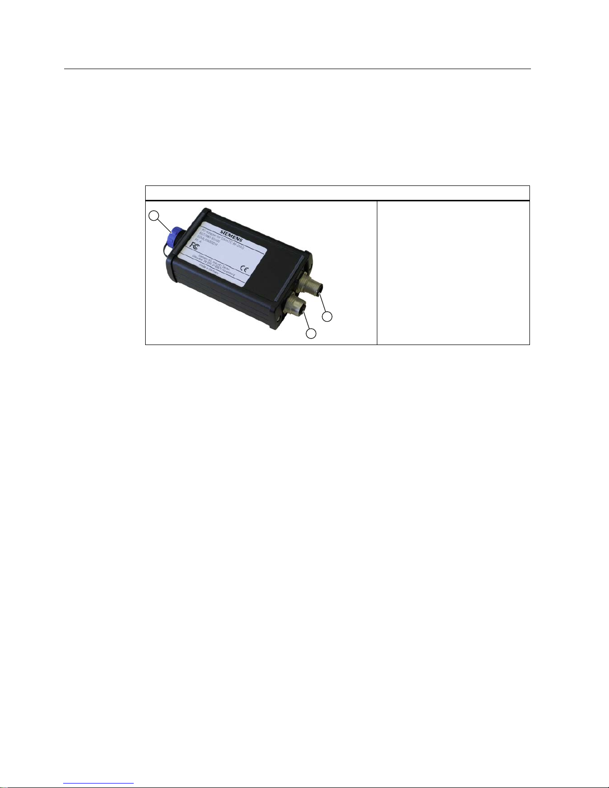
3.1.1 Description
PC adapter for SIMATIC RF-DIAG
① USB interface
② RS-422 – CM / wide-range power
supply unit
③ RS-422 – RF reader
The SIMATIC RF-DIAG product consists of a CD with software and documentation and a
hardware packet. The hardware packet consists of a PC adapter for SIMATIC RF-DIAG, a
USB connecting cable and an RS-422 cable.
The PC adapter for SIMATIC RF-DIAG is a converter from USB to RS-422. Communication
between the PC and reader can be established using the PC adapter.
Characteristics
● RS-422 to USB converter for communication with the RF620R and RF630R
● Dimensions without connecting cables: 101 x 63 x 35 mm
● CE-compliant (EU and UK versions)
● FCC-compliant for use in the USA and Canada
● Mechanically and electrically rugged design
● RS-422 interface
– With 24 VDC / 3 A for CM or wide-range power supply unit
– With 24 VDC / 3 A for reader
● Short-circuit proof
Connecting hardware
3.1 The PC adapter for SIMATIC RF-DIAG
SIMATIC RF-DIAG
Operating Manual, 09/2012, C79000-G8976-C292-01
13
Highlights
● Diagnostics via a PC with the reader supplied with power from the system
● IP65 degree of protection
● Can be used in high temperature ranges
● Use in productive operation possible
● Switchover to diagnostics mode "on the fly" (parallel to regular operation)
Note
Protection from environmental influences
The IP65 degree of protection of the PC adapter is only valid if the USB protective cap is
fitted and the corresponding RS-422 cable is connected. During diagnostics, this degree of
protection is not present.
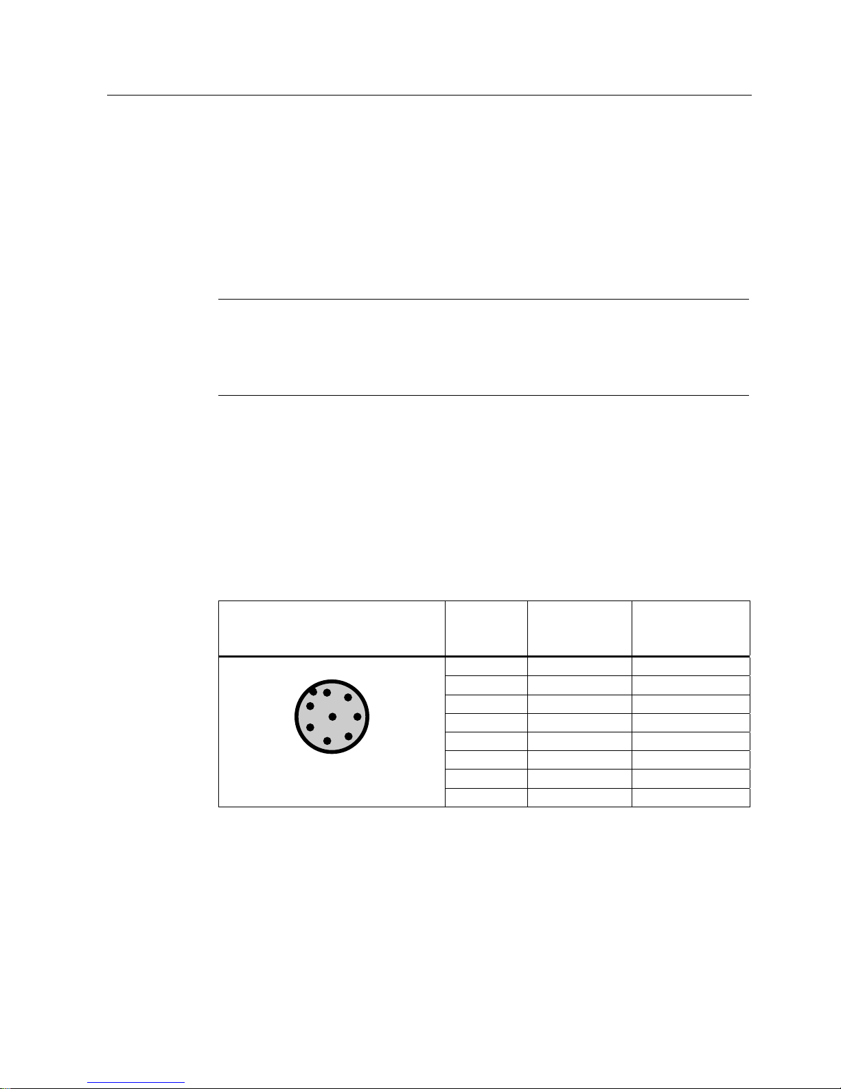
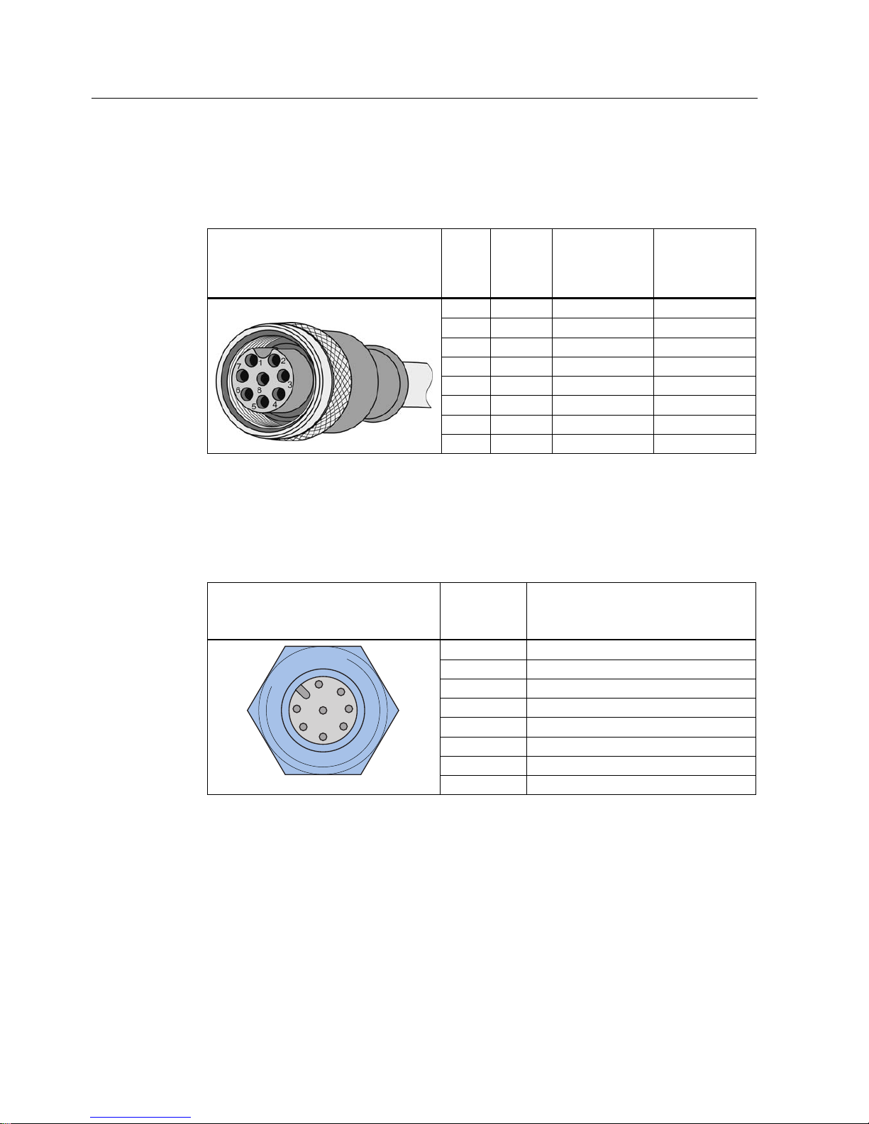
3.1.2 Pin assignment of the RS-422 interface
Pin assignment for connection to the CM or wide-range power supply unit
Pin assignment of the connector for PC adapter and CM or wide-range power supply unit
Table 3- 1 RS-422 interface of the PC adapter (male connector)
Pin Pin
Device end 8pin M12
Assignment for
CM
Assignment for
wide-range power
supply unit
1 + 24 V + 24 V
2 - Transmit Free
3 0 V 0 V
4 + Transmit Free
5 + Receive Free
6 - Receive Free
7 Free Free
8 Ground (shield) Ground (shield)
The knurled bolt of the M12 plug does not contact the shield (reader end).
Connecting hardware
3.1 The PC adapter for SIMATIC RF-DIAG
SIMATIC RF-DIAG
14 Operating Manual, 09/2012, C79000-G8976-C292-01
Pin assignment of the connecting cable between PC adapter and CM or wide-range power
supply unit
Table 3- 2 RS-422 connecting cable
View of M12 socket M12
pin
Core
color
Pin assignment
for CM
Pin assignment
for wide-range
power supply
unit
1 White 24 VDC 24 VDC
2 Brown TX neg Not used
3 green GND GND
4 Yellow TX pos Not used
5 gray RX pos Not used
6 pink RX neg Not used
7 Blue Not used Not used
8 Red Ground (shield) Ground (shield)
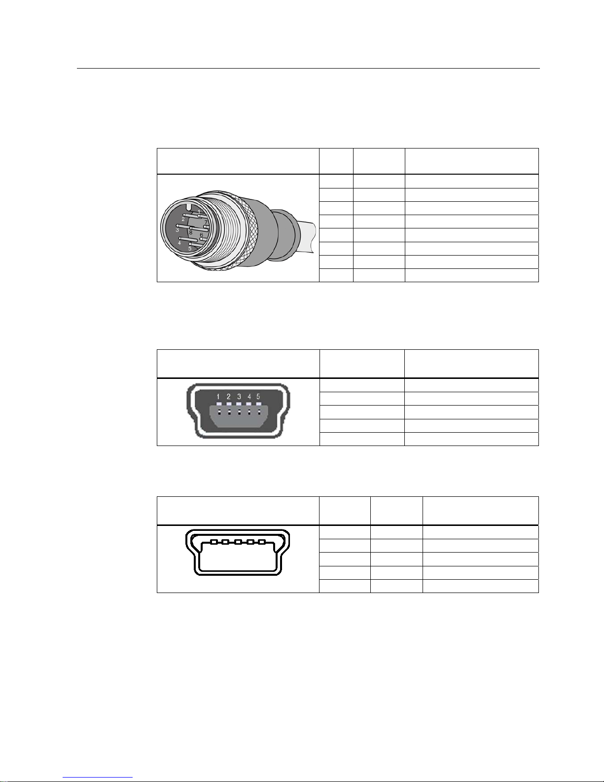
Pin assignment for connecting to the RF readers
Pin assignment of the connector for PC adapter and UHF reader
Table 3- 3 RS-422 interface of the PC adapter (female connector)
Pin Pin
Device end 8pin M12
Assignment for the RF readers
1 + 24 V
2 - Transmit
3 0 V
4 + Transmit
5 + Receive
6 - Receive
7 Free
8 Ground (shield)
The knurled bolt of the M12 plug does not contact the shield (reader end).
Connecting hardware
3.1 The PC adapter for SIMATIC RF-DIAG
SIMATIC RF-DIAG
Operating Manual, 09/2012, C79000-G8976-C292-01
15
Pin assignment of the connecting cable between PC adapter and UHF reader
Table 3- 4 RS-422 connecting cable
View of M12 plug M12
pin
Wire color Pin assignment
1 White 24 VDC
2 Brown TX neg
3 green GND
4 Yellow TX pos
5 gray RX pos
6 pink RX neg
7 Blue Not used
8 Red Ground (shield)
Pin assignment for connection to the PC
Table 3- 5 USB 2.0 mini-B connector socket of the PC adapter
View of connection socket Pin
Device side
Assignment
1 + 5 V
2 Data 3 Data +
4 ID (not used)
5 GND
Table 3- 6 USB 2.0 mini-B plug of the connecting cable
View of mini-B plug Pin
Device side
Wire color Assignment
1 Red + 5 V
2 White Data 3 green Data +
4 - ID (not used)
5 Black GND

Connecting hardware
3.1 The PC adapter for SIMATIC RF-DIAG
SIMATIC RF-DIAG
16 Operating Manual, 09/2012, C79000-G8976-C292-01
3.1.3 Technical specifications
Table 3- 7 Mechanical data
Property Description
Weight 310 g
Dimensions (L x W x H) 101 × 63 × 35 mm
Enclosure material Aluminum (painted)
Housing color Black
Installation No securing aids
Interfaces
RS422
• 1 x pin (8-pin M12, connection to CM/wide-range power supply)
• 1 x socket (8-pin M12, connection to the reader)
USB USB 2.0 Mini-B
MTBF in years 1.1x10³
Table 3- 8 Software interfaces
Property Description
Software – RS-422 SIMATIC S7 / TIA
Software – USB
• RF600
• 3964R & RF-DIAG
Table 3- 9 Electrical data
Property Description
Power supply of the PC adapter via USB
(during operation)
• Nominal value
• Permitted range
• 5 V DC
• 4.0 to 5.25 VDC
Power supply of the RF readers via RS-422
• Nominal value
• Permitted range
• 24 VDC
• 20 to 30 VDC
Current consumption
• Connection via USB and RS-422
• No connection via USB
• Via 5 VDC, approx. 30 mA; 24 VDC, approx. 15 mA
• Via 24 VDC, ≤ 5 mA
Transmission rates USB / RS-422
• 19.2 Kbps
• 57.6 Kbps
• 115.2 Kbps

Connecting hardware
3.1 The PC adapter for SIMATIC RF-DIAG
SIMATIC RF-DIAG
Operating Manual, 09/2012, C79000-G8976-C292-01
17
Table 3- 10 Ambient conditions
Property Description
Temperature range during operation -25 ℃ to +70 ℃
Temperature range during storage -40 ℃ to +85 ℃
Shock resistant to EN 60068-2-27
Vibration resistant to EN 60068-2-6
50 g, 1)
20 g,
1)
Degree of protection in accordance with
EN 60529
IP65 2)
1)
The values for shock and vibration are maximum values and must not be applied continuously nor when the USB plug is
plugged in.
2)
Only when the USB protective cap is fitted and the corresponding RS-422 cables are connected.
Connecting hardware
3.1 The PC adapter for SIMATIC RF-DIAG
SIMATIC RF-DIAG
18 Operating Manual, 09/2012, C79000-G8976-C292-01
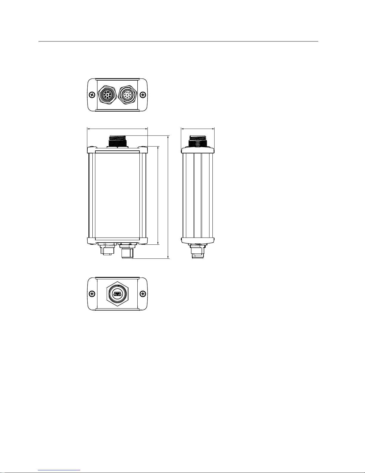
3.1.4 Dimension drawing
Figure 3-2 Dimension drawing of the PC adapter for SIMATIC RF-DIAG (all dimensions in mm)
When the USB protective cap is screwed on, the length of the adapter is 134 mm. The
tolerances are +/- 1 mm.
Connecting hardware
3.2 Connecting the hardware
SIMATIC RF-DIAG
Operating Manual, 09/2012, C79000-G8976-C292-01
19
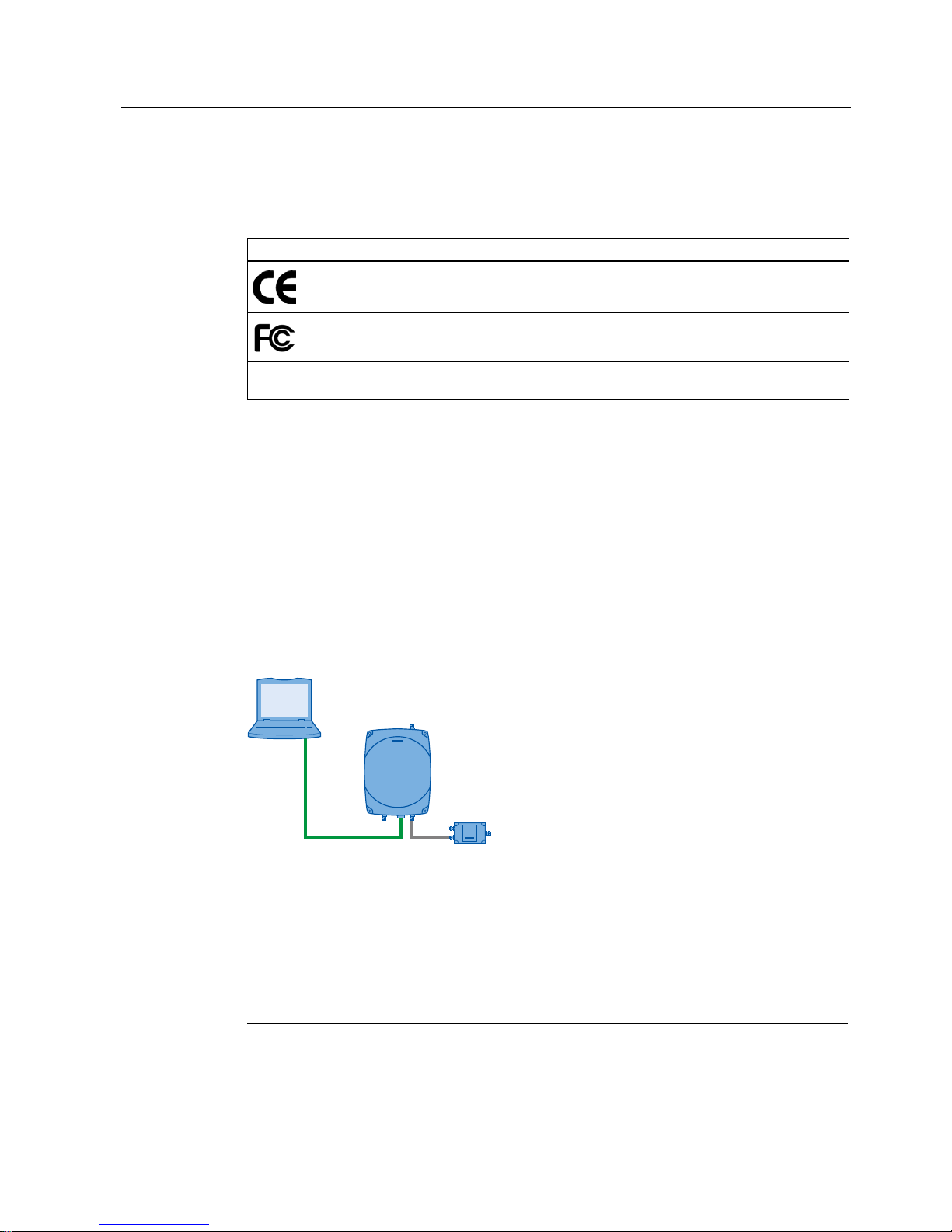
3.1.5 Certificates and approvals
Table 3- 11 Certificates and approvals for the PC adapter
Certificate Description
CE approval complying with 2004/108/EC EMC
FCC Rules, Part 15, Subpart B, Sections 15.107 and 15.109
Industry Canada Radio
Standards Specifications
CAN/CSA-CISPR 22-10 - Information technology equipment – Radio
disturbance characteristics – Limits and methods of measurement
3.2 Connecting the hardware
3.2.1 Connecting an Ethernet-based reader
Connecting an Ethernet-based reader in an isolated test environment
To set up or to diagnose an Ethernet-based reader RF640R/RF670R, you can connect the
reader to the PC using a crossover cable or an Ethernet adapter capable of cross-linking.
3*3&
:LGHUDQJHSRZHUVXSSO\XQLW
5)55)5
Figure 3-3 Connecting Ethernet-based readers to a PC
Note
Reader parameter assignment with RF-MANAGER Basic
Remember that you assign parameters and correct the readers using the RF-MANAGER
Basic. SIMATIC RF-DIAG is used only to check the current settings.
Note that the reader cannot communicate with more than one software tool at any one time.
You will find further information on connecting up and assigning parameters for an Ethernetbased reader in the manual "RF-MANAGER Basic".

Connecting hardware
3.2 Connecting the hardware
SIMATIC RF-DIAG
20 Operating Manual, 09/2012, C79000-G8976-C292-01
You require the following:
● Ethernet cable
● Adapter cable for wide-range power supply unit
● Wide-range power supply unit
Follow the steps below to connect an Ethernet-based reader to a PC:
1. Connect the PC to the reader using a crossover cable.
2. Start the SIMATIC RF-DIAG diagnostics tool and establish the connection between the
PC and reader using the software user interface as described in the sections "Starting the
softwa
re (Page 25) and "Operating the software (Page 29)".
Connecting hardware
3.2 Connecting the hardware
SIMATIC RF-DIAG
Operating Manual, 09/2012, C79000-G8976-C292-01
21
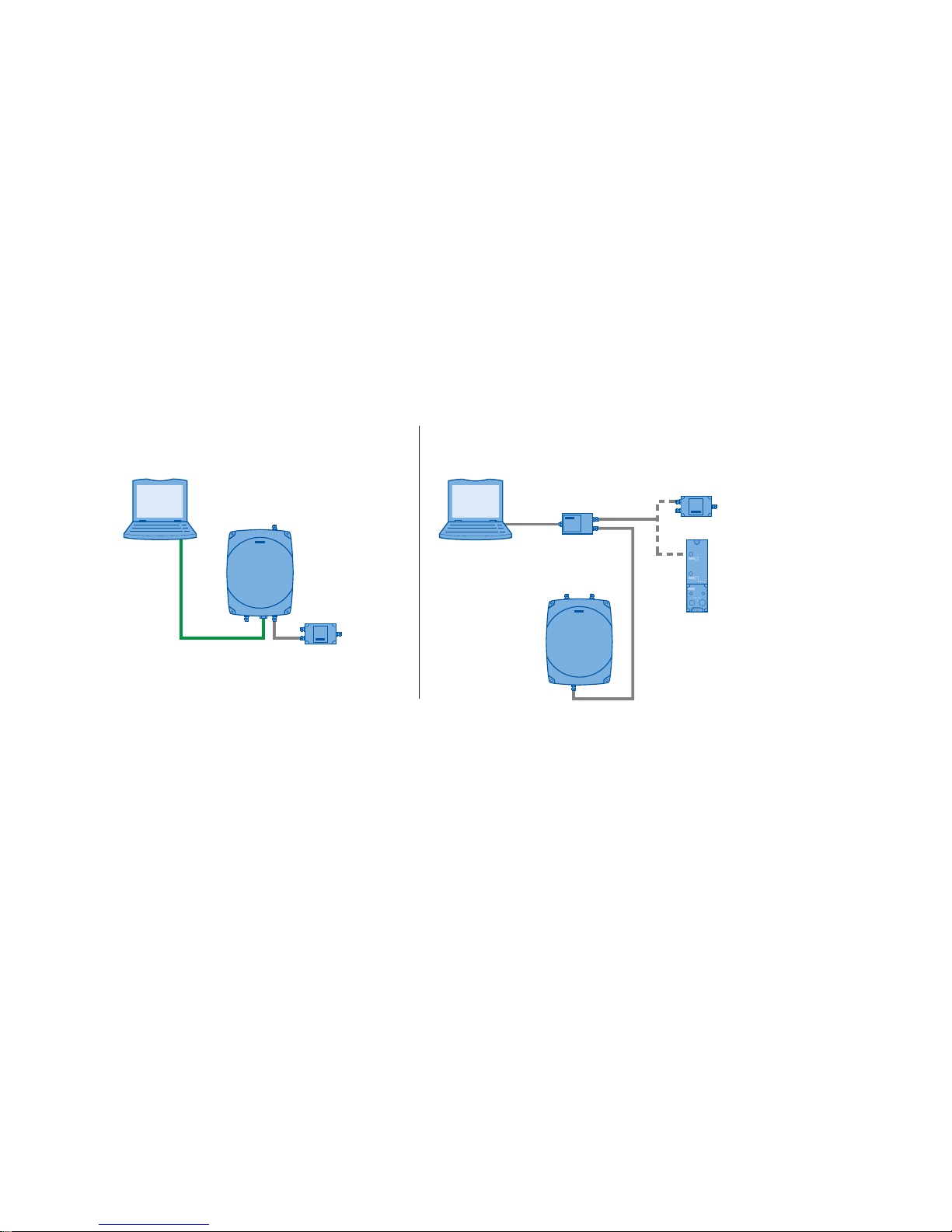
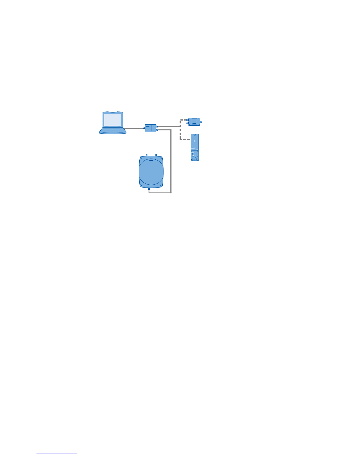
3.2.2 Connecting a serial reader
The serial readers need to be connected to the PC using the PC adapter. The following
scenarios are possible:
● Diagnostics of a serial reader in an isolated test environment
● Diagnostics of a serial reader in industrial applications
3*3&
3&DGDSWHU
:LGHUDQJHSRZHUVXSSO\XQLW
&0
5)55)5
Figure 3-4 Connecting serial readers to a PC
Diagnostics of a serial reader in an isolated test environment:
To set up an RF620R//RF630R serial reader or to run diagnostics on it, you require the
supplied PC adapter for SIMATIC RF-DIAG. To run diagnostics in an isolated test
environment, you require neither a master module nor a communications module.
You require the following:
● Wide-range power supply unit
● Adapter cable for wide-range power supply unit
● RS-422 cable (ships with product)
● USB cable (ships with product)
Follow the steps below to operate a serial reader from a PC:
1. Connect the wide-range power supply unit to the interface with an RS-422 cable.
The connected wide-range power supply unit supplies the reader with power.
2. Connect the reader to the interface with an RS-422 cable.
3. Connect the PC to the USB interface using the USB connecting cable.
4. Start the SIMATIC RF-DIAG diagnostics tool and establish the connection between the
PC and reader using the software user interface.

Connecting hardware
3.2 Connecting the hardware
SIMATIC RF-DIAG
22 Operating Manual, 09/2012, C79000-G8976-C292-01
Diagnostics of a serial reader in industrial applications:
When using a serial reader in an industrial environment, the reader is operated using CMs
and a master module. To set up an RF620R//RF630R serial reader or to run diagnostics on
it, you also require the PC adapter for SIMATIC RF-DIAG.
To run diagnostics, you need to disconnect the reader from the CM and connect both
devices to the PC adapter via the RS-422 interface. Communication between the reader and
CM is via the PC adapter.
To run diagnostics, you now need to connect the PC to the reader via the USB interface of
the PC adapter. As soon as the PC has been connected to the PC adapter, communication
between the CM and reader is interrupted. You can now read out the data or adapt
parameters using the PC. If you disconnect the PC and PC adapter in the software user
interface, the reader is automatically restarted. Then disconnect the USB cable to prevent a
restart of the reader in diagnostics mode and to restore the communications connection
between reader and CM. Data that has not been saved is lost. During this procedure, the
power supply is always maintained.
Note
Sequence when disconnecting
Always disconnect the PC and PC adapter first using the software user interface before you
unplug the USB cable.
You require the following:
● Operational CM connected using a suitable connecting cable between the CM and reader
● 2 x RS-422 cable (one cable ships with the product, use a second cable from the plant)
● USB cable (ships with product)
Follow the steps below to operate a serial reader in an industrial environment:
1. Connect the CM to the interface with an RS-422 cable.
The reader is supplied with power via the connected CM.
2. Connect the reader to the interface with an RS-422 cable.
3. Connect the PC to the USB interface using the USB connecting cable.
As soon as you connect the PC, the connection between the CM and reader is
interrupted. Communication with the connected PC is now via the USB interface.
4. Start the SIMATIC RF-DIAG diagnostics tool and establish the connection between the
PC and reader using the software user interface.

SIMATIC RF-DIAG
Operating Manual, 09/2012, C79000-G8976-C292-01
23
Software installation
4
4.1 Installing the software
To use the SIMATIC RF-DIAG diagnostics tool, you do not need to perform any installation.
Follow the steps below to copy the diagnostics tool to your PC:
1. Insert the supplied CD in your CD drive.
2. Right-click on the "SIMATIC RF-DIAG" folder on the CD and select the "Copy" command
in the shortcut menu.
3. Select the folder on your PC to which you want to copy the diagnostics tool.
4. Right-click on the folder and select the "Paste" command in the shortcut menu.
Note
Installing .NET Framework
If an error message appears when you start the diagnostics tool SIMATIC RF-DIAG, this
indicates that the required version of .NET Framework is not yet on your system.
The required version of .NET Framework is available on the CD in the "DotNET Framework
2.0" folder.
Run both setups "NetFx20SP2_x86.exe" and then "NDP20SP2-KB958481-x86.exe" to install
the required components.
4.2 Installation and use of the USB driver
To operate the SIMATIC RF-DIAG application with a serial reader (RF620R/RF630R), the
appropriate USB driver "Silicon Labs CP210x USB to UART Bridge" Version 6.5.3.0 is
required for communication via the PC adapter for SIMATIC RF-DIAG. The following steps
are described based on the "Windows XP" operating system.

Software installation
4.2 Installation and use of the USB driver
SIMATIC RF-DIAG
24 Operating Manual, 09/2012, C79000-G8976-C292-01
A. Check for and uninstall older variants of the USB driver "Silicon Labs CP210x USB to
UART Bridge" version 6.5.3.0
1. Open "Computer Management " with "Start > Settings > Control Panel > Administrative
Tools".
2. Select "Device Manager" and open the subfolder "Ports (COM & LPT)".
If the USB driver "Silicon Labs CP210x USB to UART Bridge" was installed previously,
you will find the following as one of the entries:
"Silicon Labs CP210x USB to UART Bridge (COM<x >)" (e.g. "Silicon Labs CP210x USB
to UART Bridge (COM5)").
If there is no"Silicon Labs CP210x USB to UART Bridge" entry in the "Ports (COM &
LPT)" subfolder, you can cancel the steps already taken in the open dialog boxes and
start installation of the USB driver.
3. Select the entry with the right mouse button and then select "Properties" in the shortcut
menu.
In the "Driver" tab of the dialog box that now opens, you will find the "Driver Version"
entry.
4. If the driver version is lower than 6.5.3, click "Cancel".
5. Uninstall the driver by selecting the USB driver with the right mouse button and selecting
"Uninstall" in the shortcut menu.
6. Follow the instructions of the wizard.
B. Installation of the USB driver for the PC adapter for SIMATIC RF-DIAG
1. Install the correct variant (32/64-bit) of the USB driver using the setup
"CP210xVCPInstaller.exe" in "<CD>\SiLabs\MCU\CP210x\Windows_XP_S2K3_Vista_7".
2. Following installation, insert the USB cable that is already connected to the PC adapter
into the PC.
At the bottom right of the screen, you will see a message that a new device has been
detected and the initialization of the PC adapter is completed.
3. The new device appears in the Device Manager as "Silicon Labs CP210x USB to UART
Bridge".
To identify the COM port that needs to be set in the SIMATIC RF-DIAG application for serial
readers, follow the steps below:
C. Selecting the COM port using SIMATIC RF-DIAG
1. Open "Computer Management " with "Start > Settings > Control Panel > Administrative
Tools".
2. Select "Device Manager" and open the subfolder "Ports (COM & LPT)".
3. If the USB driver of the PC adapter for SIMATIC RF-DIAG was correctly installed earlier,
you
will find the following as one of the entries:
"Silicon Labs CP210x USB to UART Bridge (COM<x >)" (e.g. "Silicon Labs CP210x USB
to UART Bridge (COM5)").
This means that you select COM<x> from the drop-down list in the SIMATIC RF-DIAG
application as the port (in the example above "COM5").
 Loading...