

Siemens SIMATIC HMI TP900 Comfort, SIMATIC HMI KP400 Comfort, SIMATIC HMI KTP400 Comfort, SIMATIC HMI KP1200 Comfort, SIMATIC HMI TP1200 Comfort Operating Instructions Manual
...
___________________
___________________
___________________
___________________
___________________
___________________
___________________
___________________
___________________
___________________
___________________
___________________
SIMATIC HMI
HMI devices
Comfort Panels
Operating Instructions
07/2017
A5E36770603
Preface
Overview
1
Safety instructions
2
Mounting and connecting the
HMI device
3
Commissioning the device
4
Commissioning a project
5
Operating a project
6
Maintenance and care
7
Technical information
8
Technical Support
A
Markings and symbols
B
Abbreviations
C
-AB
Siemens AG
Division Digital Factory
Postfach 48 48
90026 NÜRNBERG
GERMANY
Ⓟ
Copyright © Siemens AG 2017.
All rights reserved
Legal information
Warning notice system
DANGER
indicates that death or severe personal injury will result if proper precautions are not taken.
WARNING
indicates that death or severe personal injury may result if proper precautions are not taken.
CAUTION
indicates that minor personal injury can result if proper precautions are not taken.
NOTICE
indicates that property damage can result if proper precautions are not taken.
Qualified Personnel
personnel qualified
Proper use of Siemens products
WARNING
Siemens products may only be used for the applications described in the catalog and in the relevant technical
maintenance are required to ensure that the products operate safely and without any problems. The permissible
ambient conditions must be complied with. The information in the relevant documentation must be observed.
Trademarks
Disclaimer of Liability
This manual contains notices you have to observe in order to ensure your personal safety, as well as to prevent
damage to property. The notices referring to your personal safety are highlighted in the manual by a safety alert
symbol, notices referring only to property damage have no safety alert symbol. These notices shown below are
graded according to the degree of danger.
If more than one degree of danger is present, the warning notice representing the highest degree of danger will
be used. A notice warning of injury to persons with a safety alert symbol may also include a warning relating to
property damage.
The product/system described in this documentation may be operated only by
task in accordance with the relevant documentation, in particular its warning notices and safety instructions.
Qualified personnel are those who, based on their training and experience, are capable of identifying risks and
avoiding potential hazards when working with these products/systems.
Note the following:
documentation. If products and components from other manufacturers are used, these must be recommended
or approved by Siemens. Proper transport, storage, installation, assembly, commissioning, operation and
All names identified by ® are registered trademarks of Siemens AG. The remaining trademarks in this publication
may be trademarks whose use by third parties for their own purposes could violate the rights of the owner.
We have reviewed the contents of this publication to ensure consistency with the hardware and software
described. Since variance cannot be precluded entirely, we cannot guarantee full consistency. However, the
information in this publication is reviewed regularly and any necessary corrections are included in subsequent
editions.
for the specific
07/2017 Subject to change

Preface
Purpose of the operating instructions
Basic knowledge required
Scope of the operating instructions
Name
Type
Article number
SIMATIC HMI KTP400 Comfort
4" Touch/Key Panel
6AV2124-2DC01-0AX0
SIMATIC HMI KP700 Comfort
7" Key device
6AV2124-1GC01-0AX0
SIMATIC HMI TP700 Comfort
7" Touch Panel
6AV2124-0GC01-0AX0
SIMATIC HMI KP900 Comfort
9" Key Panel
6AV2124-1JC01-0AX0
SIMATIC HMI TP900 Comfort
9" Touch Panel
6AV2124-0JC01-0AX0
SIMATIC HMI TP1200 Comfort
12" Touch Panel
6AV2124-0MC01-0AX0
6AV2124-1QC02-0AX1
6AV2124-0UC02-0AX1
These operating instructions contain information based on the requirements defined by
DIN EN 62079 for mechanical engineering documentation. This information relates to the
place of use, transport, storage, mounting, use and maintenance.
These operating instructions are intended for:
● Users
● Commissioning engineers
● Maintenance personnel
Read especially the information in the chapter "Safety instructions" (Page 27).
You can find more information such as operating instructions, examples and reference
information in the online help of WinCC.
General knowledge of automation technology and process communication is needed to
understand the operating instructions. Knowledge of personal computers and the Microsoft
operating systems is required to understand this manual.
The operating instructions apply to the following HMI devices in conjunction with the
WinCC software package:
SIMATIC HMI KP400 Comfort 4" Key Panel 6AV2124-1DC01-0AX0
SIMATIC HMI KP1200 Comfort 12'' Key Panel 6AV2124-1MC01-0AX0
SIMATIC HMI KP1500 Comfort 15'' Key Panel 6AV2124-1QC02-0AX0,
Comfort Panels
Operating Instructions, 07/2017, A5E36770603-AB
SIMATIC HMI TP1500 Comfort 15" Touch Panel 6AV2124-0QC02-0AX0,
6AV2124-0QC02-0AX1
SIMATIC HMI TP1900 Comfort 19" Touch Panel 6AV2124-0UC02-0AX0,
SIMATIC HMI TP2200 Comfort 22" Touch Panel 6AV2124-0XC02-0AX0,
6AV2124-0XC02-0AX1
3

Preface
NOTICE
Manual is part of the HMI device
Trademarks
Style conventions
Style Convention
Scope
menu commands.
<F1>, <Alt+P>
Keyboard operation
Note
A note contains important information about the product described in the manual and its use,
or a specific section of the manual to which you should pay particular attention.
This manual is part of the HMI device and is also required for repeat commissioning. Keep
all supplied and supplementary documentation for the entire service life of the HMI device.
Provide all stored documents to subsequent owners of the HMI device.
The following designations marked with the symbol ® are registered trademarks of
Siemens AG:
● HMI
● SIMATIC
● WinCC
®
®
®
"Add screen"
"File > Edit" Operational sequences, for example, menu commands, shortcut
• Terminology that appears in the user interface, for example, dia-
log names, tabs, buttons, menu commands
• Required input, for example, limits, tag values.
• Path information
Please observe notes labeled as follows:
Comfort Panels
4 Operating Instructions, 07/2017, A5E36770603-AB

Preface
Naming conventions
Term
Applies to
System
Comfort HMI
device
HMI device
Device
Key model
Key HMI device
Touch model
Touch HMI device
Comfort V1
devices
Comfort V1.1
devices
• System
• Machining center
• One or more machines
• KP400 Comfort
• KTP400 Comfort
• KP700 Comfort
• TP700 Comfort
• KP900 Comfort
• TP900 Comfort
• KP1200 Comfort
• TP1200 Comfort
• KP400 Comfort
• KP700 Comfort
• KP900 Comfort
• KP1200 Comfort
• KTP400 Comfort
• TP700 Comfort
• TP900 Comfort
• TP1200 Comfort
• KP400 Comfort
• KTP400 Comfort
• KP700 Comfort, F-State <19
• TP700 Comfort, F-State <22
• KP900 Comfort, F-State <18
• TP900 Comfort, F-State <19
• KP1200 Comfort, F-State <20
• TP1200 Comfort, F-State <20
• KP700 Comfort, F-State ≥19
• TP700 Comfort, F-State ≥22
• KP900 Comfort, F-State ≥18
• TP900 Comfort, F-State ≥19
• KP1200 Comfort, F-State ≥20
• TP1200 Comfort, F-State ≥20
• KP1500 Comfort
• TP1500 Comfort
• TP1900 Comfort
• TP2200 Comfort
• KP1500 Comfort
• TP1500 Comfort
• TP1900 Comfort
• TP2200 Comfort
• KP1500 Comfort, MLFB
6AV2124-1QC02-0AX0
• TP1500 Comfort, MLFB
2
6AV2124-0QC02-0AX0
2
• TP1900 Comfort, MLFB
2
6AV2124-0UC02-0AX0
2
• TP2200 Comfort, MLFB
2
6AV2124-0XC02-0AX0
2
2
2
2
2
2
2
Comfort Panels
Operating Instructions, 07/2017, A5E36770603-AB
5
Preface
Term
Applies to
Comfort (TIA Portal) or
1
2
You can find the F-State (functional status) on the rating plate of the HMI device.
Figures
Comfort V2
devices
WinCC 1 WinCC V11 (TIA Portal) or higher
Devices are configurable as of WinCC V11. The description in this manual relates to V14 or
higher.
for configuring devices of 12" and
smaller
• KP1500 Comfort, MLFB
6AV2124-1QC02-0AX1
• TP1500 Comfort, MLFB
6AV2124-0QC02-0AX1
• TP1900 Comfort, MLFB
6AV2124-0UC02-0AX1
• TP2200 Comfort, MLFB
6AV2124-0XC02-0AX1
WinCC V11 SP2
HSP Comfort (TIA
Portal) or higher for
configuring
Comfort V1
devices as of 15"
WinCC V14 SP1
HSP 0211 HMI
TP1500 - TP2200
higher for configuring
Comfort V2 devices as
of 15"
Features of the various device versions:
● Comfort V1: Display sizes 4"...22", with audio double socket and USB socket type Mini-B,
Windows CE 6 operating system
● Comfort V1.1: Display sizes 7"...12", with audio OUT and USB socket type Mini-B,
Windows CE 6 operating system
● Comfort V2: Display sizes 15"...22", with audio OUT without USB socket type Mini-B,
Windows Embedded Compact 2013 operating system
This manual contains figures of the described devices. The figures can deviate from the
particularities of the delivered device.
Picture components are marked with black position numbers on a white background
①, ②, ③, etc.
Steps in the figures are identified with white process numbers on a black background
according to the sequence in which they have to be executed: , , , ...
Comfort Panels
6 Operating Instructions, 07/2017, A5E36770603-AB

Table of contents
Preface ........................................................................................................................................ 3
1 Overview .................................................................................................................................... 13
2 Safety instructions ....................................................................................................................... 27
3 Mounting and connecting the HMI device ....................................................................................... 33
1.1 Product description ............................................................................................................ 13
1.2 Scope of delivery ............................................................................................................... 15
1.3 Configuration of the devices .............................................................................................. 16
1.3.1 KP400 Comfort and KTP400 Comfort ................................................................................ 16
1.3.2 KP700 Comfort to KP1500 Comfort, TP700 Comfort to TP2200 Comfort ........................... 18
1.3.3 Interfaces .......................................................................................................................... 20
1.4 Accessories ....................................................................................................................... 22
1.5 The HMI device in the operating process ........................................................................... 24
1.6 Software add-ons .............................................................................................................. 25
2.1 General safety instructions ................................................................................................ 27
2.2 Security management for HMI devices............................................................................... 29
2.3 Notes about usage ............................................................................................................ 30
3.1 Preparing for installation .................................................................................................... 33
3.1.1 Checking the package contents ......................................................................................... 33
3.1.2 Checking the operating conditions ..................................................................................... 34
3.1.3 Selecting a mounting position ............................................................................................ 34
3.1.4 Checking clearances ......................................................................................................... 37
3.1.5 Preparing the mounting cutout ........................................................................................... 38
3.1.6 Labeling the function keys ................................................................................................. 39
3.2 Mounting the device .......................................................................................................... 42
3.3 Connecting the device ....................................................................................................... 46
3.3.1 Notes on connection .......................................................................................................... 46
3.3.2 Connecting the equipotential bonding circuit ...................................................................... 47
3.3.3 Connecting the power supply ............................................................................................. 49
3.3.4 Connecting the configuration PC ....................................................................................... 51
3.3.5 Connecting the controller ................................................................................................... 53
3.3.6 Connecting a USB device .................................................................................................. 55
3.3.7 Connecting a printer .......................................................................................................... 56
3.3.8 Connecting an audio device............................................................................................... 57
3.3.9 Switching on and testing the HMI device ............................................................................ 58
3.3.10 Securing the cables ........................................................................................................... 59
Comfort Panels
Operating Instructions, 07/2017, A5E36770603-AB
7

Table of contents
4 Commissioning the device ........................................................................................................... 61
4.1 Overview ............................................................................................................................61
4.1.1 Firmware and software .......................................................................................................61
4.1.2 Memory concept .................................................................................................................61
4.1.3 Changing the memory cards ...............................................................................................65
4.1.4 Front operator controls .......................................................................................................67
4.2 Operating the device ..........................................................................................................69
4.2.1 Reference for system keys .................................................................................................69
4.2.2 Entering values with system keys .......................................................................................73
4.3 Parameter assignment for Comfort Panel ...........................................................................74
4.3.1 Desktop and Start Center ...................................................................................................74
4.3.2 Installed programs ..............................................................................................................75
4.3.3 Security mode ....................................................................................................................76
4.3.3.1 Overview ............................................................................................................................76
4.3.3.2 Using the HMI device in password-protected security mode................................................77
4.3.4 Control Panel .....................................................................................................................78
4.3.4.1 Opening the settings ..........................................................................................................78
4.3.4.2 Overview of functions .........................................................................................................78
4.3.4.3 Operating the Control Panel ...............................................................................................80
4.3.4.4 Display types for the screen keyboard ................................................................................80
4.3.5 Configuring operation .........................................................................................................83
4.3.5.1 Changing display brightness ...............................................................................................83
4.3.5.2 Change screen orientation..................................................................................................84
4.3.5.3 Configuring the screen keyboard ........................................................................................85
4.3.5.4 Setting the character repeat rate of the screen keyboard ....................................................86
4.3.5.5 Setting the double-click ......................................................................................................87
4.3.5.6 Calibrating the touch screen ...............................................................................................
88
4.3.5.7 Restarting the HMI device ..................................................................................................89
4.3.6 General settings .................................................................................................................91
4.3.6.1 Regional and language settings ..........................................................................................91
4.3.6.2 Setting the date and time ....................................................................................................91
4.3.6.3 Changing password protection ...........................................................................................93
4.3.6.4 Setting the screen saver .....................................................................................................94
4.3.6.5 Configuring transfer ............................................................................................................96
4.3.6.6 Memory management.........................................................................................................99
4.3.6.7 Backing up registry information and temporary data..........................................................102
4.3.6.8 Changing the printer properties ........................................................................................103
4.3.6.9 Displaying general system properties ...............................................................................104
4.3.6.10 Displaying information about the Comfort Panel................................................................105
4.3.6.11 Setting volume and sound ................................................................................................106
4.3.7 Changing Internet settings ................................................................................................109
4.3.7.1 Changing general settings ................................................................................................109
4.3.7.2 Setting the proxy server ....................................................................................................110
4.3.7.3 Changing Internet security settings ...................................................................................111
4.3.7.4 Activating encryption protocols .........................................................................................112
4.3.7.5 Importing, displaying and deleting certificates ...................................................................113
Comfort Panels
8 Operating Instructions, 07/2017, A5E36770603-AB

Table of contents
5 Commissioning a project ............................................................................................................ 159
4.3.8 Enabling PROFINET ....................................................................................................... 115
4.3.9 Enabling NTP .................................................................................................................. 117
4.3.10 Configuring network operation ......................................................................................... 118
4.3.10.1 Overview ......................................................................................................................... 118
4.3.10.2 Specifying the computer name of the HMI device............................................................. 120
4.3.10.3 Entering the IP address and name server ........................................................................ 121
4.3.10.4 Changing MPI/PROFIBUS DP settings ............................................................................ 124
4.3.10.5 Specifying the logon data ................................................................................................ 125
4.3.10.6 Configuring e-mail ........................................................................................................... 126
4.3.10.7 Configuring Telnet for remote control ............................................................................... 128
4.3.10.8 Configure Sm@rt Server ................................................................................................. 129
4.3.10.9 Configure Web Server ..................................................................................................... 131
4.3.11 Functions for service and commissioning ......................................................................... 134
4.3.11.1 Saving to external storage medium – backup ................................................................... 134
4.3.11.2 Restoring from external storage medium – Restore .......................................................... 136
4.3.11.3 Update operating system ................................................................................................. 139
4.3.11.4 Load project from external storage medium ..................................................................... 142
4.3.11.5 Using automatic backup .................................................................................................. 146
4.3.11.6 Editing IP addresses and communication connections ..................................................... 149
4.3.12 Uninterruptible power supply ........................................................................................... 155
4.3.12.1 Setting the uninterruptible power supply .......................................................................... 155
4.3.12.2 State of the uninterruptible power supply ......................................................................... 157
5.1 Overview ......................................................................................................................... 159
5.2 Operating modes ............................................................................................................. 160
5.3 Using existing projects ..................................................................................................... 161
5.4 Data transmission options ............................................................................................... 161
5.5 Transferring a project with WinCC ................................................................................... 162
5.5.1 Configuring data channel and setting transfer mode ........................................................ 162
5.5.2 Starting the transfer ......................................................................................................... 162
5.5.3 Testing a project .............................................................................................................. 164
5.6 Backup and restore ......................................................................................................... 165
5.6.1 Overview ......................................................................................................................... 165
5.6.2 Backing up and restoring data of the HMI device ............................................................. 166
5.7 Updating the operating system ........................................................................................ 167
5.7.1 Updating the operating system ........................................................................................ 167
5.7.2 Updating the operating system of the HMI device ............................................................ 168
5.8 Managing add-ons and license keys ................................................................................ 170
5.8.1 Managing add-ons ........................................................................................................... 170
5.8.2 Transferring license keys ................................................................................................. 171
5.8.3 Managing license keys .................................................................................................... 171
Comfort Panels
Operating Instructions, 07/2017, A5E36770603-AB
9

Table of contents
6 Operating a project..................................................................................................................... 173
7 Maintenance and care ................................................................................................................ 183
8 Technical information ................................................................................................................. 185
6.1 Overview ..........................................................................................................................173
6.2 Function keys ...................................................................................................................176
6.3 Direct keys .......................................................................................................................176
6.4 Setting the project language .............................................................................................177
6.5 Input of values ..................................................................................................................178
6.6 Entering and editing numerical values ..............................................................................179
6.7 Entering or changing alphanumeric values .......................................................................180
6.8 Displaying infotext ............................................................................................................181
6.9 Closing the project............................................................................................................182
7.1 Maintaining and caring for the touch screen and the keyboard cover ................................183
7.2 Clean screen for Touch HMI devices ................................................................................183
7.3 Spare parts and repairs ....................................................................................................184
7.4 Recycling and disposal .....................................................................................................184
8.1 Software license agreements............................................................................................185
8.2 Certificates and approvals ................................................................................................185
8.3 Electromagnetic compatibility ...........................................................................................188
8.4 Mechanical ambient conditions .........................................................................................190
8.4.1 Storage conditions............................................................................................................190
8.4.2 Operating Conditions ........................................................................................................190
8.5 Climatic ambient conditions ..............................................................................................191
8.5.1 Long-term storage ............................................................................................................191
8.5.2 Transport and short-term storage .....................................................................................191
8.5.3 Operating Conditions ........................................................................................................191
8.5.4 Climate diagram ...............................................................................................................192
8.6 Information on insulation tests, protection class and degree of protection..........................193
8.7 Dimension drawings .........................................................................................................194
8.7.1 Dimension drawings of the KP400 Comfort .......................................................................194
8.7.2 Dimension drawings of the KP700 Comfort .......................................................................195
8.7.3 Dimension drawings of the KP900 Comfort .......................................................................196
8.7.4 Dimension drawings of the KP1200 Comfort .....................................................................197
8.7.5 Dimension drawings of the KP1500 Comfort V1................................................................198
8.7.6 Dimension drawings of the KP1500 Comfort V2................................................................199
8.7.7 Dimension drawings of the KTP400 Comfort.....................................................................200
8.7.8 Dimension drawings of the TP700 Comfort .......................................................................201
8.7.9 Dimension drawings of the TP900 Comfort .......................................................................202
8.7.10 Dimension drawings of the TP1200 Comfort .....................................................................203
8.7.11 Dimension drawings of the TP1500 Comfort V1 ................................................................204
8.7.12 Dimension drawings of the TP1500 Comfort V2 ................................................................205
Comfort Panels
10 Operating Instructions, 07/2017, A5E36770603-AB

Table of contents
A Technical Support ..................................................................................................................... 231
B Markings and symbols ............................................................................................................... 233
C Abbreviations ............................................................................................................................ 235
Glossary ................................................................................................................................... 237
Index ....................................................................................................................................... 243
8.7.13 Dimension drawings of the TP1900 Comfort V1 ............................................................... 206
8.7.14 Dimension drawings of the TP1900 Comfort V2 ............................................................... 207
8.7.15 Dimension drawings of the TP2200 Comfort V1 ............................................................... 208
8.7.16 Dimension drawings of the TP2200 Comfort V2 ............................................................... 209
8.7.17 Dimensions for labeling strips .......................................................................................... 210
8.8 Technical specifications ................................................................................................... 213
8.8.1 KP400 Comfort to KP1200 Comfort, KTP400 Comfort to TP1200 Comfort ....................... 213
8.8.2 KP1500 Comfort, TP1500 Comfort to TP2200 Comfort .................................................... 215
8.9 Bit assignment of the direct keys ..................................................................................... 218
8.9.1 KTP400 Comfort.............................................................................................................. 218
8.9.2 KP400 Comfort ................................................................................................................ 218
8.9.3 KP700 Comfort ................................................................................................................ 219
8.9.4 TP700 Comfort ................................................................................................................ 219
8.9.5 KP900 Comfort ................................................................................................................ 220
8.9.6 TP900 Comfort ................................................................................................................ 220
8.9.7 KP1200 Comfort .............................................................................................................. 221
8.9.8 TP1200 Comfort .............................................................................................................. 221
8.9.9 KP1500 Comfort .............................................................................................................. 222
8.9.10 TP1500, TP1900 and TP2200 Comfort ............................................................................ 222
8.10 Description of the ports .................................................................................................... 223
8.10.1 Power supply................................................................................................................... 223
8.10.2 PROFIBUS ...................................................................................................................... 223
8.10.3 PROFINET (LAN) ............................................................................................................ 224
8.10.4 PROFINET (LAN) 10/100/1000 Mb ..................................................................................
224
8.10.5 USB ................................................................................................................................ 225
8.10.6 Audio .............................................................................................................................. 225
8.11 Communication with controllers ....................................................................................... 226
8.12 Scope of functions with WinCC ........................................................................................ 227
A.1 Service and support ........................................................................................................ 231
A.2 Troubleshooting .............................................................................................................. 232
A.3 System events ................................................................................................................. 232
B.1 Safety-relevant symbols .................................................................................................. 233
Comfort Panels
Operating Instructions, 07/2017, A5E36770603-AB
11

Table of contents
Comfort Panels
12 Operating Instructions, 07/2017, A5E36770603-AB

1
1.1
Product description
Features of the SIMATIC HMI Comfort Panels
Enclosure
Aluminum pressure enclosures for all 7" models and larger
Mounting format
the HMI device.
Interfaces
Display
Completely dimmable
Operation
SIMATIC HMI Comfort Panels are a fully redesigned product line of the Touch Panels and
Key Panels. The product line includes the following models:
● Five key panels (operated by keyboard) with 4", 7", 9", 12" and 15" displays
● Six touch panels (operated by touch screen) with 7", 9", 12", 15", 19" and 22" displays.
● One Key&Touch Panel (operated by keyboard and touch screen) with 4" display size
All devices offer the same excellent functionality and are configured exclusively with the
innovative HMI software, WinCC. The software is integrated into the engineering framework,
"Totally Integrated Automation Portal".
Plastic enclosure for the 4" model
Mounting and operation of the touch models in horizontal and vertical format
The respective format must be selected during the configuration of the user
interface. The display orientation must also be changed in the Start Center of
2 PROFINET interfaces (exception: KP400 Comfort and KTP400 Comfort have
only 1 PROFINET interface)
Additional gigabit PROFINET interface for devices of 15" or more
1 PROFIBUS interface
USB 2.0 ports:
• USB host interface (type A)
– 1 x for 4" model
– 2 x for 7", 9" and 12" models
• USB device interface (type Mini B)
– 1 x with Comfort V1/1.1 devices
High-resolution TFT display in widescreen format with 16 million colors
Wide viewing angle
Text and numbers are entered with the key models using the keypad system
familiar from cell phones
Intuitive operating scheme of the key models based on the proven technique
used for cell phone keypads
All freely configurable function keys have LEDs
All keys have a clear pressure point for additional safety in the operation
Comfort Panels
Operating Instructions, 07/2017, A5E36770603-AB
13

Overview
Software
for SIMATC controllers, display of trends (f(x), f(t)), etc.
Data storage
No data inconsistency in the event of a power failure. Applies to the HMI device
and inserted SIMATIC HMI memory cards ≥ 2 GB.
Controller
Device variants for special requirements
1.1 Product description
Internet Explorer to display web pages
Viewer for PDF, Excel and Word documents
Runtime software with logging and scripting functionality, system diagnostics
2 memory card slots
• One slot for storing user data
• One slot for using the service concept for simplified restart in the event of
service. Project data and device settings are updated automatically on the
system card.
The system diagnostics of SIMATIC controllers can be read from the HMI
device, which means no additional programming device is required.
The following device variants are available for use in areas with special requirements:
● Comfort PRO Panels, all-round IP65 protected for use directly at the machine or in harsh
environmental conditions.
● Comfort Outdoor Panels for indoor and outdoor areas, e.g. oil & gas, marine or cooling
systems.
● Comfort Panels INOX for areas with increased safety and hygiene requirements, e.g.
food, beverages and tobacco industries, pharmaceutical industry or fine chemicals
industry.
Comfort Panels
14 Operating Instructions, 07/2017, A5E36770603-AB
Overview
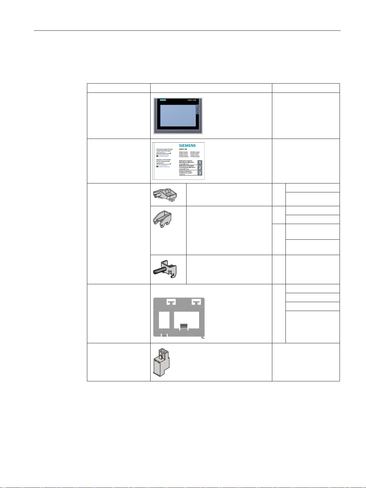
1.2
Scope of delivery
Name
Figure
Quantity
KTP400 Comfort
TP700 Comfort
KP700 Comfort
KP900 Comfort
TP2200 Comfort
KTP400 Comfort
KP400 Comfort
TP700 Comfort
1.2 Scope of delivery
The scope of delivery of the HMI device includes the following components:
HMI device
Installation instructions
(Quick Install Guide)
Mounting clips with
grub screw
Plastic mounting clip 6
Aluminum mounting clip 12
Steel mounting clip 12
1
1
KP400 Comfort
16 TP900 Comfort
TP1200 Comfort
KP1200 Comfort
TP1500 Comfort
KP1500 Comfort
TP1900 Comfort
Strain relief Example: Strain relief KTP400/KP400
Power supply
connector
Comfort Panels
Operating Instructions, 07/2017, A5E36770603-AB
1
KP700 Comfort
1
15
Overview
1.3
Configuration of the devices
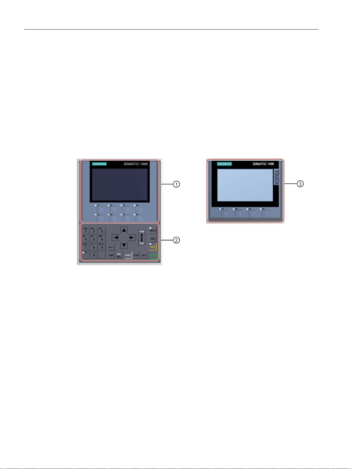
1.3.1
KP400 Comfort and KTP400 Comfort
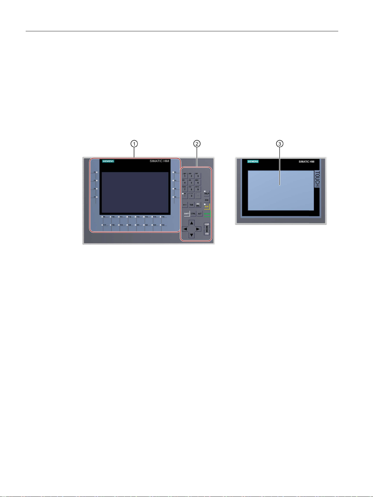
Front view
①
Display with function keys
②
Keyboard / system keys
③
Touch screen display with function keys
1.3 Configuration of the devices
The following sections describe the basic design of the KP400 Comfort and KTP400 Comfort
HMI devices.
The figure below shows the front view of the HMI devices, KP400 Comfort (left) and KTP400
Comfort (right):
Comfort Panels
16 Operating Instructions, 07/2017, A5E36770603-AB
Overview
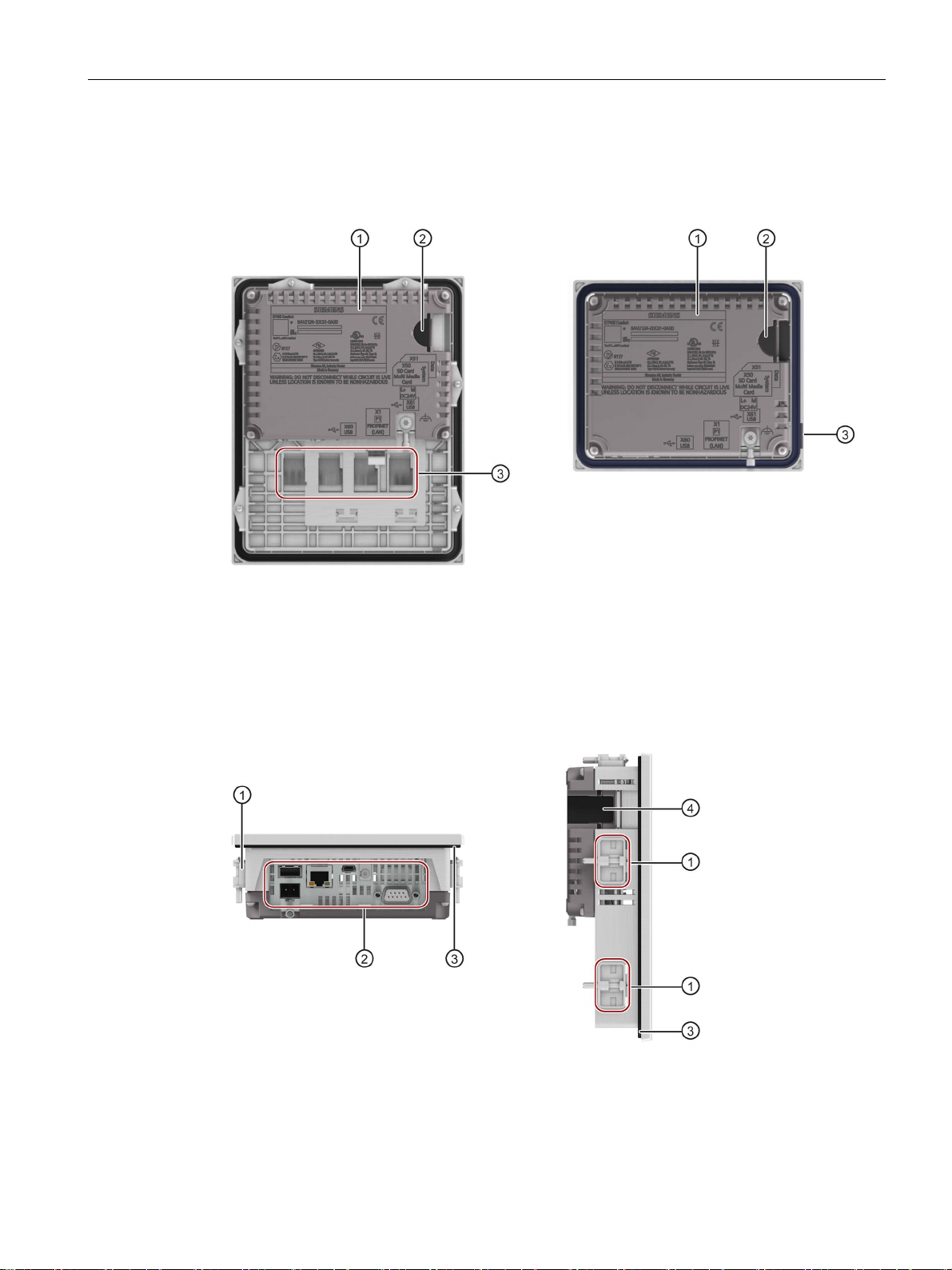
Rear view
①
Rating plate
②
Slots for SD memory cards - accessible from the device side
③
Labeling strip
Side view
①
Cutouts for mounting clips
②
Interfaces
③
Mounting seal
④
Slots for SD memory cards
1.3 Configuration of the devices
The figure below shows the rear view of the HMI devices, KP400 Comfort (left) and KTP400
Comfort (right):
The figure below shows the side views of the HMI devices, KP400 and KTP400 Comfort:
Comfort Panels
Operating Instructions, 07/2017, A5E36770603-AB
17
Overview
1.3.2
KP700 Comfort to KP1500 Comfort, TP700 Comfort to TP2200 Comfort
Front view
①
The number of function keys varies depending on display size
②
Keyboard / system keys
③
Touch screen display
1.3 Configuration of the devices
The following sections describe the basic design of the devices with 7" or larger displays,
using the KP700 Comfort and TP700 Comfort as examples. The enclosure dimensions and
form for the other models may differ from the illustrations shown.
The figure below shows the front view of the HMI devices, using the KP700 Comfort and
TP700 Comfort as examples.
Display with function keys
Comfort Panels
18 Operating Instructions, 07/2017, A5E36770603-AB
Overview
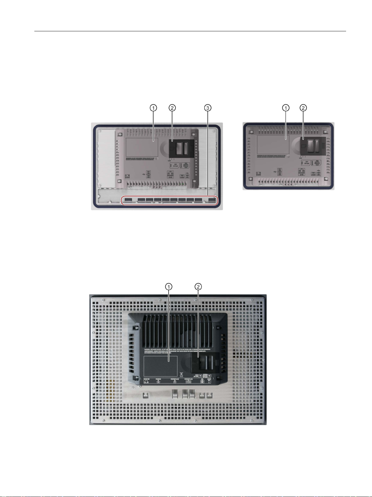
Rear view
Comfort V1/1.1 devices
①
Rating plate
②
Slots for SD memory cards
③
Labeling strip
Comfort V2 devices
①
Rating plate
②
Slots for SD memory cards
1.3 Configuration of the devices
The figure below shows back views of Comfort V1/V1.1 devices with KP700 Comfort and
TP700 Comfort as examples.
The figure below shows the back view of Comfort V2 devices with TP1500 Comfort as an
example.
Comfort Panels
Operating Instructions, 07/2017, A5E36770603-AB
19
Overview
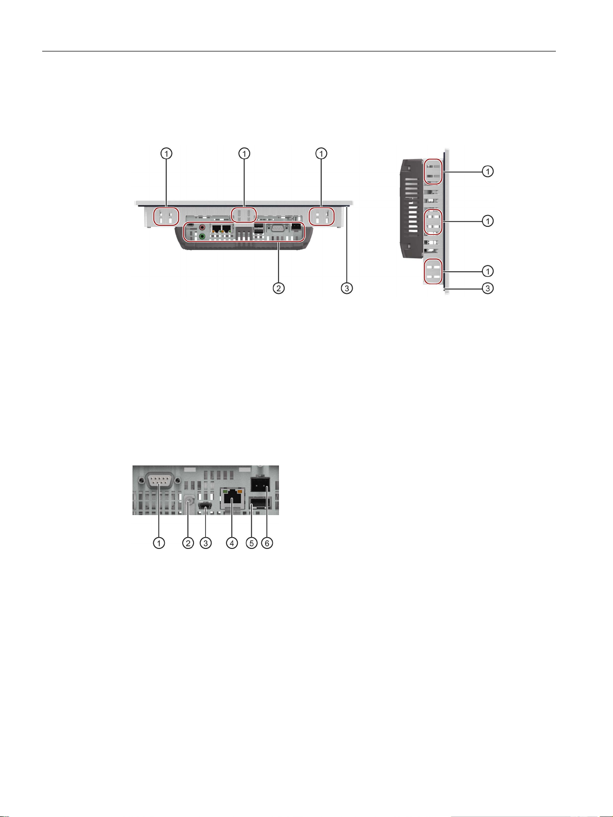
Side view
①
Cutouts for mounting clips
②
Interfaces
③
Mounting seal
1.3.3
Interfaces
Interfaces for the 4" models
①
X2 PROFIBUS (Sub-D RS422/485)
④
X1 PROFINET (LAN), 10/100 Mb
②
Connection for equipotential bonding (ground)
⑤
X61 USB type A
③
X60 USB type Mini B
⑥
X80 power supply connector
1.3 Configuration of the devices
The figure below shows the side views of the HMI devices with the Comfort V1 devices,
KP700 Comfort and TP700 Comfort, as examples.
The figure below shows the ports of the Comfort V1 devices, KP400 and KTP400 Comfort.
Comfort Panels
20 Operating Instructions, 07/2017, A5E36770603-AB
Overview
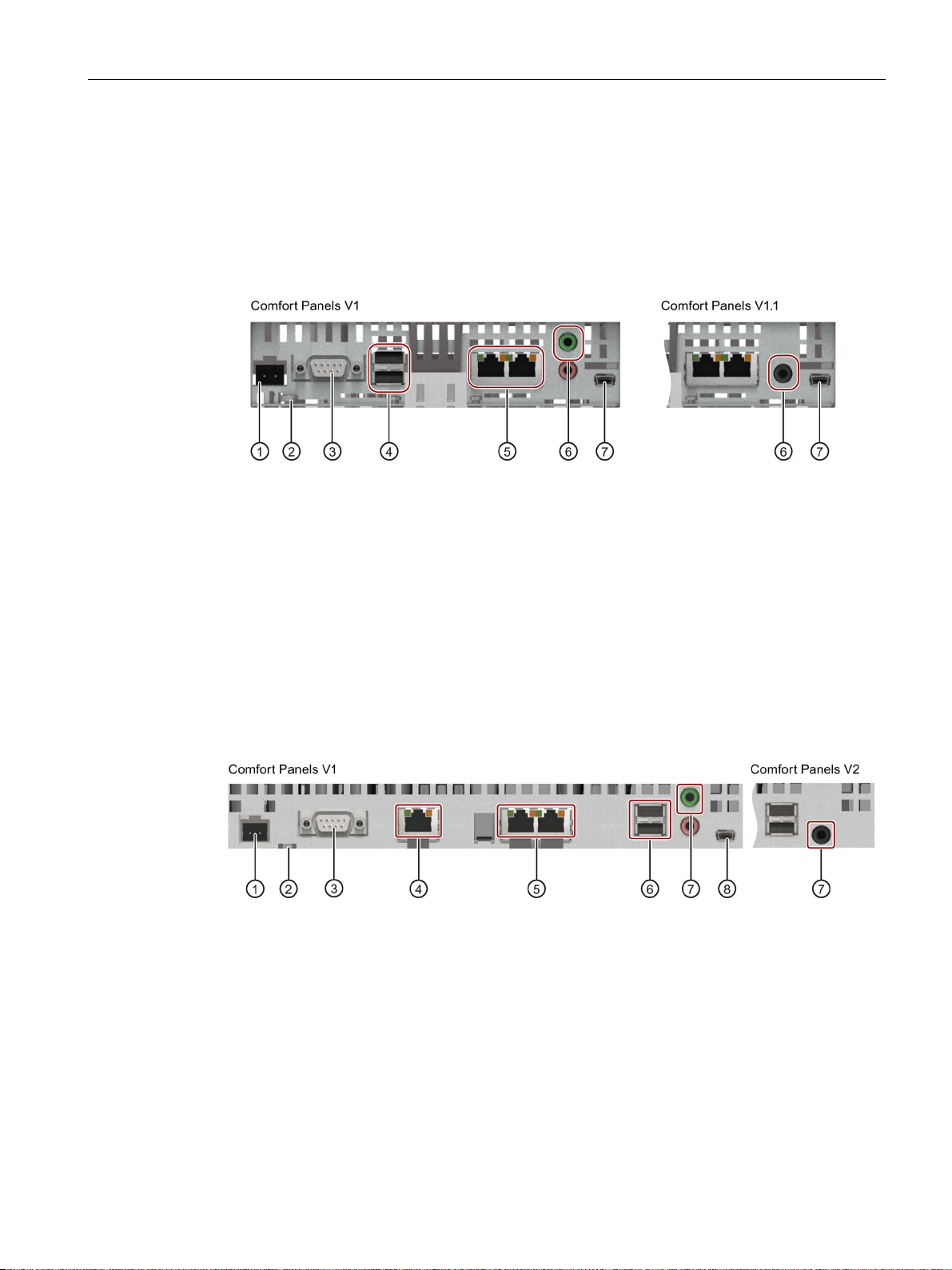
Interfaces for the 7", 9" and 12" models
①
X80 power supply connector
⑤
X1 PROFINET (LAN), 10/100 Mb
②
Connection for equipotential bonding (ground)
⑥
X90 Audio Line OUT
③
X2 PROFIBUS (Sub-D RS422/485)
⑦
X60 USB type Mini B
④
X61 / X62 USB type A
Interfaces for the 15", 19" and 22" models
①
X80 power supply connector
⑤
X1 PROFINET (LAN), 10/100 Mb
②
Connection for equipotential bonding (ground)
⑥
X61 / X62 USB type A
③
X2 PROFIBUS (Sub-D RS422/485)
⑦
X90 Audio Line OUT
④
X3 PROFINET (LAN), 10/100/1000 Mb
⑧
X60 USB type Mini B
1.3 Configuration of the devices
The figure below shows the interfaces for the following HMI devices:
● KP700 and TP700 Comfort
● KP900 and TP900 Comfort
● KP1200 and TP1200 Comfort
The figure below shows the interfaces for the following HMI devices:
● KP1500 and TP1500 Comfort
● TP1900 Comfort
● TP2200 Comfort
Comfort Panels
Operating Instructions, 07/2017, A5E36770603-AB
21

Overview
Additional information
See also
1.4
Accessories
HMI I/O components
Name
Article number
Converter RS 422 to RS 232 for connecting third-party controllers
6AV6671-8XE00-....
Plug for the power supply of the HMI device
6AV6671-8XA00-....
"...." stands for the variant key of the article number.
Protective films
Name
Article number
Protective film 4" widescreen for KTP400 Comfort
6AV2124-6DJ00-....
Protective film 7" widescreen for TP700 Comfort
6AV2124-6GJ00-....
Protective film 9" widescreen for TP900 Comfort
6AV2124-6JJ00-....
Protective film 12" widescreen for TP1200 Comfort
6AV2124-6MJ00-....
Protective film 15" widescreen for TP1500 Comfort
6AV2124-6QJ00-....
Protective film 19" widescreen for TP1900 Comfort
6AV2124-6UJ00-....
Protective film 22" widescreen for TP2200 Comfort
6AV2124-6XJ00-....
"...." stands for the variant key of the article number.
1.4 Accessories
Use the X1 or X60 interface to connect a configuration PC. Use the X61 / X62 interfaces to
connect peripheral devices such as a printer or keyboard. Use the X90 interface to connect a
loudspeaker.
You can fasten the USB and PROFINET connecting cables to the rear panel of the HMI
device with cable ties.
With the 4" and 7" models, protect the cables with a separate strain relief. Install the strain
relief on the HMI device.
Description of the ports (Page 223)
An accessory kit with the necessary accessories is included with the HMI device. Additional
accessories can be found on the Internet
(https://mall.industry.siemens.com/mall/en/WW/Catalog/Products/10144445
).
This section contains the number of accessories available at the time of publication of the
operating instructions.
Details such as the delivery quantity and technical specifications of accessories can be
found in the Industry Mall under the respective article numbers.
90° elbow adapter for RS422/RS485 interface 6AV6671-8XD00-....
Comfort Panels
22 Operating Instructions, 07/2017, A5E36770603-AB

Overview
Memory media
Name
Article number
SIMATIC HMI memory card
6AV2181-8XP00-....
"...." stands for the variant key of the article number.
Fasteners
Name
Article number
TP900 Comfort, KP900 Comfort, TP1200 Comfort and KP1200 Comfort
Set of steel mounting clamps for KP1500 Comfort, TP1500 Comfort,
TP1900 Comfort and TP2200 Comfort
6AV6671-8XK00-....
Memory card lock protection for 4" Comfort Panels
6AV2181-4DM10-....
Memory card lock protection for 7" - 22" Comfort Panels
6AV2181-4XM00-....
"...." stands for the variant key of the article number.
Input help
Name
Article number
Touch pen system for resistive and capacitive touch systems
6AV2181-8AV20-...
"...." stands for the variant key of the article number.
Other accessories
1.4 Accessories
Use only the following storage media for the HMI device.
SIMATIC HMI USB stick 6AV2181-8AS20-....
Read the notes on using the memory media in the section "Memory concept (Page 61)".
Set of plastic mounting clamps for KP400 Comfort and KTP400 Comfort 6AV6671-8KX00-....
Set of aluminum mounting clamps for TP700 Comfort, KP700 Comfort,
6AV6671-8XK00-....
Additional USB accessories can be found on the Internet in the following entry:
FAQ 19188460 (https://support.industry.siemens.com/cs/ww/en/view/19188460
)
Comfort Panels
Operating Instructions, 07/2017, A5E36770603-AB
23
Overview
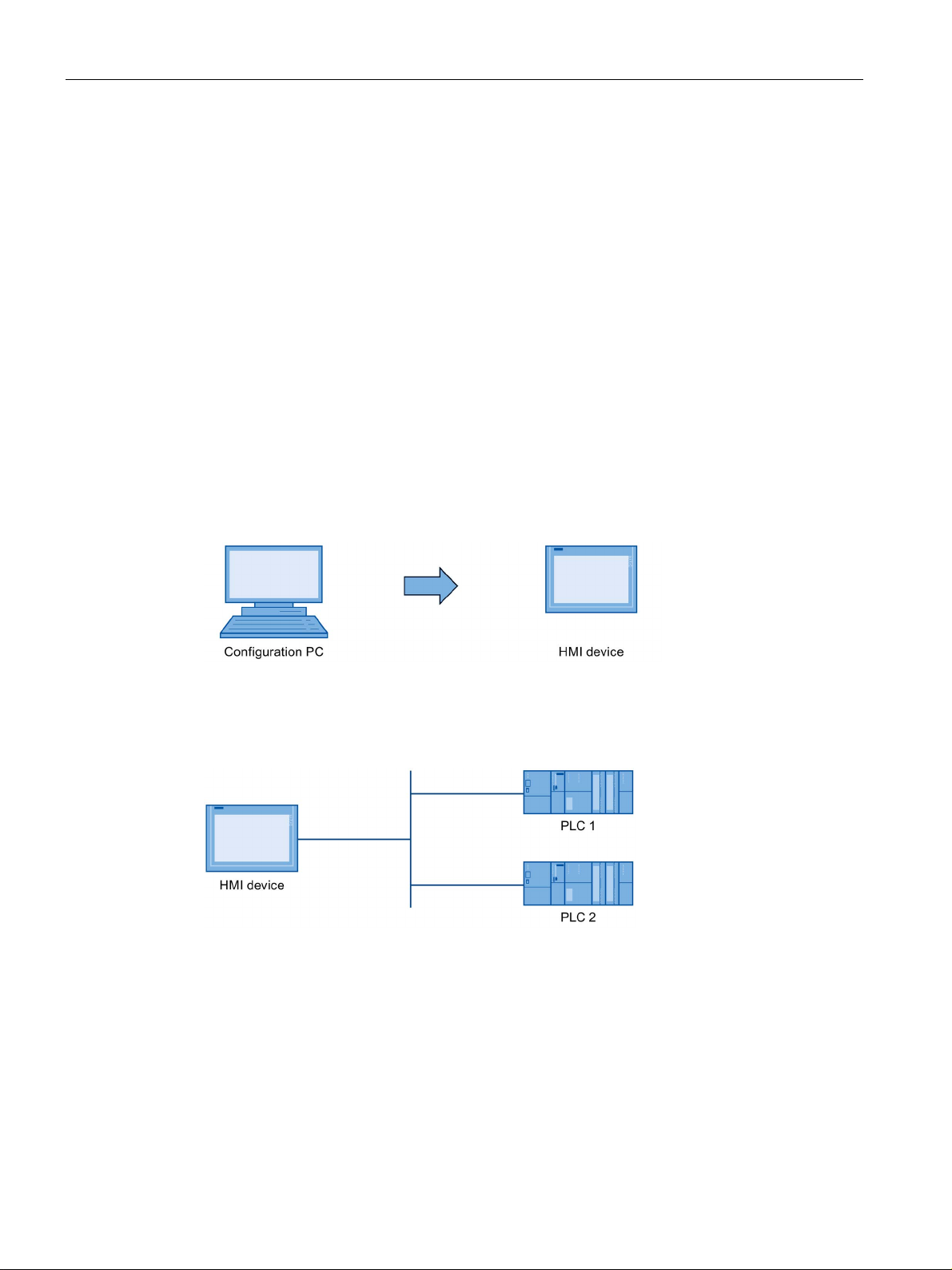
1.5
The HMI device in the operating process
Configuration
Process management
1.5 The HMI device in the operating process
The HMI device is part of the operating process. The following two phases are key to the
way the HMI device is integrated in the process:
● Configuration
● Process management
During the configuration phase, you create the user interfaces for operation and monitoring
of the technical process to a configuration PC with WinCC as of version 11. Configuration
also includes:
● Creating project data
● Saving project data
● Testing project data
● Simulating project data
After compiling the configuration, you download the project to the HMI device.
Process management is marked by two-way communication between HMI device and
controller.
You then use the HMI device to operate and monitor the process.
Comfort Panels
24 Operating Instructions, 07/2017, A5E36770603-AB

Overview
1.6
Software add-ons
Add-on
Description
Server on the HMI device.
and electronic signature.
the USB port.
Word Viewer 3
The Word Viewer enables you to view Word documents.
files.
PDF output for all HMI device print options.
1
2
3
4
5
You can find information on licensing in the TIA information system
See also
1.6 Software add-ons
The following software add-ons are available for the HMI devices:
WinCC /Sm@rtServer 1
• Web Server
WinCC /Audit 2 The WinCC /Audit add-on extends the HMI device to
WinCC /ProDiag 5 Use the option WinCC /ProDiag to configure detailed
Uninterruptable Power Supply (UPS) with
USB support
PDF Viewer 3 You can view PDF documents using the PDF Viewer.
Excel Viewer 3 The Excel Viewer enables you to view Excel documents.
Media Player 3 You can use the Media Player to play audio and video
Internet Explorer 3 The Internet Explorer provides you access to the Internet.
Printer driver 4 The printer driver option enables PostScript, HTML and
4
The WinCC /Sm@rtServer add-on enables you to access
a remote HMI device from the HMI device or PC via
Ethernet. It also enables you to set up communication
between different HMI systems. The
WinCC /Sm@rtServer option also lets you use the Web
include functions for recording operations in an audit trail
plant and machine monitoring
When interfacing an uninterruptible power supply, the
HMI device is shut down in a controlled manner after a
buffer time in the event of a power failure. The HMI
devices support SITOP DC UPS modules connected via
Transferred with the project; a license key is required for use up to WinCC V14 (TIA Portal), as of
WinCC V14 (TIA Portal), a license key is no longer required
Transferred with the project; a license key is required for use
Pre-installed; no license key is required for use
Must be transferred as an option; no license key is required for use
Approved printers for SIMATIC HMI Panels
(http://support.automation.siemens.com/WW/view/en/11376409
Printing with SIMATIC Comfort HMI devices
(http://support.automation.siemens.com/WW/view/en/58205602
Comfort Panels
Operating Instructions, 07/2017, A5E36770603-AB
)
)
25

Overview
1.6 Software add-ons
Comfort Panels
26 Operating Instructions, 07/2017, A5E36770603-AB

2
2.1
General safety instructions
Open equipment and the Machinery Directive
WARNING
The device constitutes open equipment on the back side
Electrocution risk when control cabinet is open
The device may only be used in machines which comply with the Machinery Directive
The device constitutes open equipment on the back side. This means that the device may
only be integrated in an enclosure or cabinet which provides front access for operating the
device. The enclosure, the cabinet or the electrical operating rooms must provide protection
against electric shock and the spread of fire. The requirements regarding the mechanical
strength must also be considered.
Access to the enclosure or cabinet in which the device is installed should only be possible
by means of a key or tool and for trained and qualified personnel.
When you open the control cabinet, there may be a dangerous voltage at certain areas or
components.
Touching these areas or components can cause electrocution.
Always disconnect the cabinet from the mains before opening it.
The Machinery Directive specifies precautions to be taken when commissioning and
operating machinery within the European Economic Area.
Failure to follow these precautions is a breach of the Machinery Directive. Such failure may
also cause personal injury and damage depending on the machine operated.
The machine in which the HMI device is to be operated must conform to Directive
2006/42/EC.
Comfort Panels
Operating Instructions, 07/2017, A5E36770603-AB
27
Safety instructions
Hazardous areas
WARNING
Explosion Hazard
Risque d'Explosion
Strong high-frequency radiation
NOTICE
Observe immunity to high-frequency radiation
ESD
See also
2.1 General safety instructions
When operating the HMI device in hazardous areas the following warning applies.
Do not disconnect while circuit is live unless area is known to be non-hazardous.
Substitution of components may impair suitability for Class I, Division 2 or Zone 2.
Ne pas déconnecter pendant que le circuit est sous tension, sauf si la zone est nondangereuse. Le remplacement de composants peut compromettre leur capacité à satisfaire
à la Classe I, Division 2 ou Zone 2.
The device has an increased immunity to high frequency radiation according to the
specifications on electromagnetic compatibility in the technical specifications.
Radiation exposure in excess of the specified immunity limits can impair device functions
and result in malfunctions and therefore injuries or damage.
Read the information on immunity to high frequency radiation in the technical specifications.
An electrostatically sensitive device is equipped with electronic components. Due to their
design, electronic components are sensitive to overvoltage and thus to the discharge of
static electricity. Note the corresponding regulations when handling ESD.
Electromagnetic compatibility (Page 188)
Comfort Panels
28 Operating Instructions, 07/2017, A5E36770603-AB

Safety instructions
Industrial Security
Disclaimer for third-party software updates
Notes on protecting administrator accounts
2.2
Security management for HMI devices
2.2 Security management for HMI devices
Siemens provides products and solutions with industrial security functions that support the
secure operation of plants, systems, machines and networks.
In order to protect plants, systems, machines and networks against cyber threats, it is
necessary to implement – and continuously maintain – a holistic, state-of-the-art industrial
security concept. Siemens’ products and solutions only form one element of such a concept.
Customer is responsible to prevent unauthorized access to its plants, systems, machines
and networks. Systems, machines and components should only be connected to the
enterprise network or the internet if and to the extent necessary and with appropriate security
measures (e.g. use of firewalls and network segmentation) in place.
Additionally, Siemens’ guidance on appropriate security measures should be taken into
account. For more information about industrial security, please visit
(http://www.siemens.com/industrialsecurity
Siemens’ products and solutions undergo continuous development to make them more
secure. Siemens strongly recommends to apply product updates as soon as available and to
always use the latest product versions. Use of product versions that are no longer supported,
and failure to apply latest updates may increase customer’s exposure to cyber threats.
).
To stay informed about product updates, subscribe to the Siemens Industrial Security RSS
Feed under (http://www.siemens.com/industrialsecurity
This product includes third-party software. Siemens AG only provides a warranty for
updates/patches of the third-party software, if these have been distributed as part of a
Siemens software update service contract or officially released by Siemens AG. Otherwise,
updates/patches are undertaken at your own risk. You can find more information about our
Software Update Service offer on the Internet at Software Update Service
(
http://www.automation.siemens.com/mcms/automation-software/en/software-update-
service).
A user with administrator privileges has extensive access and manipulation options in the
system.
Therefore, ensure there are adequate safeguards for protecting the administrator accounts
to prevent unauthorized changes. To do this, use secure passwords and a standard user
account for normal operation. Other measures, such as the use of security policies, should
be applied as needed.
).
Comfort Panels
Operating Instructions, 07/2017, A5E36770603-AB
You can find additional information on security management of HMI devices on the Internet
at the following address:
Panel Security Guidelines (https://support.industry.siemens.com/cs/de/en/view/109481300
)
29

Safety instructions
2.3
Notes about usage
NOTICE
The HMI device is approved for indoor use only.
Note
Operate the device only in a normal atmospheric environment
The technical characteristics of the device described in the operating instructions are
g
composition.
Industrial applications
Use in mixed-use zone
Use in residential areas
Note
HMI device not intended for use in residential area
The HMI device is not intended for use in residential areas. Operation of an HMI device in
residential areas can have a negative influence on radio or TV reception.
2.3 Notes about usage
The HMI device may be damaged if it is operated outdoors.
Operate the HMI device indoors only.
uaranteed if you operate the device in normal ambient air conditions with usual air
The HMI device is designed for industrial applications. It conforms to the following standards:
● Requirements for emissions EN 61000-6-4: 2007
● Requirements for interference immunity EN 61000-6-2: 2005
Under certain circumstances you can use the HMI device in a mixed-use zone. A mixed-use
zone is used for housing and commercial operations that do not have a significant impact on
residents.
When you use the HMI device in a mixed-use zone, you must ensure that the limits of the
generic standard EN 61000-6-3 regarding emission of radio frequency interference are
observed. Suitable measures for achieving these limits for use in a mixed-use zone include:
● Installation of the HMI device in grounded control cabinets
● Use of filters in electrical supply lines
Individual acceptance is required.
Comfort Panels
30 Operating Instructions, 07/2017, A5E36770603-AB
 Loading...