

Siemens SIMATIC HMI TP27,SIMATIC HMI TP37 Equipment Manual
Artisan Technology Group is your source for quality
new and certied-used/pre-owned equipment
• FAST SHIPPING AND
DELIVERY
• TENS OF THOUSANDS OF
IN-STOCK ITEMS
• EQUIPMENT DEMOS
• HUNDREDS OF
MANUFACTURERS
SUPPORTED
• LEASING/MONTHLY
RENTALS
• ITAR CERTIFIED
SECURE ASSET SOLUTIONS
SERVICE CENTER REPAIRS
Experienced engineers and technicians on staff
at our full-service, in-house repair center
Instra
Remotely inspect equipment before purchasing with
our interactive website at www.instraview.com
Contact us: (888) 88-SOURCE | sales@artisantg.com | www.artisantg.com
SM
REMOTE INSPECTION
View
WE BUY USED EQUIPMENT
Sell your excess, underutilized, and idle used equipment
We also offer credit for buy-backs and trade-ins
www.artisantg.com/WeBuyEquipment
LOOKING FOR MORE INFORMATION?
Visit us on the web at www.artisantg.com for more
information on price quotations, drivers, technical
specications, manuals, and documentation
SIMATIC HMI
TP27, TP37
Touch Panels
Equipment Manual
Preface, Contents
1
Part I Introduction
2
3
Part II Functions of the
Touch Panels
11
12
Part III Installation and
Commissioning
13
14
Part IV Device Description and
Maintenance
Part V Appendices
Glossary, Index
18
A
E
6AV3991–1AJ02–0AB0
Release 01/00

Safety Guidelines
!
!
This manual contains notices which you should observe to ensure your own personal safety, as
well as to protect the product and connected equipment. These notices are highlighted in the
manual by a warning triangle and are marked as follows according to the level of danger:
Warning
indicates that death, severe personal injury or substantial property damage can result if proper
precautions are not taken.
Caution
indicates that minor personal injury or property damage can result if proper precautions are not
taken.
Note
draws your attention to particularly important information on the product, handling the product,
or to a particular part of the documentation.
Qualified Personnel
Correct Usage
!
Approvals
Trademarks
Equipment may be commissioned and operated only by qualified personnel. Qualified personnel within the meaning of the safety notices in this manual are persons who are authorized to
commission, ground and identify equipment, systems and circuits in accordance with safety
engineering standards.
Note the following:
Warning
The equipment may be used only for the applications stipulated in the catalog and in the technical description and only in conjunction with other equipment and components recommended
or approved by Siemens.
Startup must not take place until it is established that the machine, which is to accommodate
this component, is in conformity with the guideline 89/392/EEC.
Faultless and safe operation of the product presupposes proper transportation, proper storage,
erection and installation as well as careful operation and maintenance.
The approvals that apply to the device are detailed in the Chapter Technical Data.
SIMATICR, SIMATIC HMIR, SIMATIC Multi PanelR, SIMATIC Multifunctional PanelR,
ProTool/LiteR, ProToolR, ProTool/ProR and MP270R are registered trademarks of Siemens
AG.
Some of the other designations used in these documents are also registered trademarks; the
owner’s rights may be violated if they are used be third parties for their own purposes.
Impressum
The reproduction, transmission or use of this document or its
contents is not permitted without express written authority.
Offenders will be liable for damages. All rights, including rights
created by patent grant or registration of a utility model or design,
are reserved.
Siemens AG,
Automation & Drives
SIMATIC Human Machine Interface
Postfach 4848, D-90327 Nuernberg
Siemens Aktiengesellschaft Order No. 6AV3991–1AJ02–0AB0
Editor and Publisher: A&D PT1
Disclaimer of LiabilityCopyright E Siemens AG 1999 All rights reserved
We have checked the contents of this manual for agreement with
the hardware and software described. Since deviations cannot be
precluded entirely , we cannot guarantee full agreement. However ,
the data in this manual are reviewed regularly and any necessary
corrections included in subsequent editions. Suggestions for improvement are welcomed.
Technical data subject to change.
E Siemens AG 1999

Preface
Purpose
Organization of
the manual
This equipment manual provides operation, installation, configuration and
system service personnel with information concerning functionality, operation and technical design of the Touch Panels TP27 and TP37.
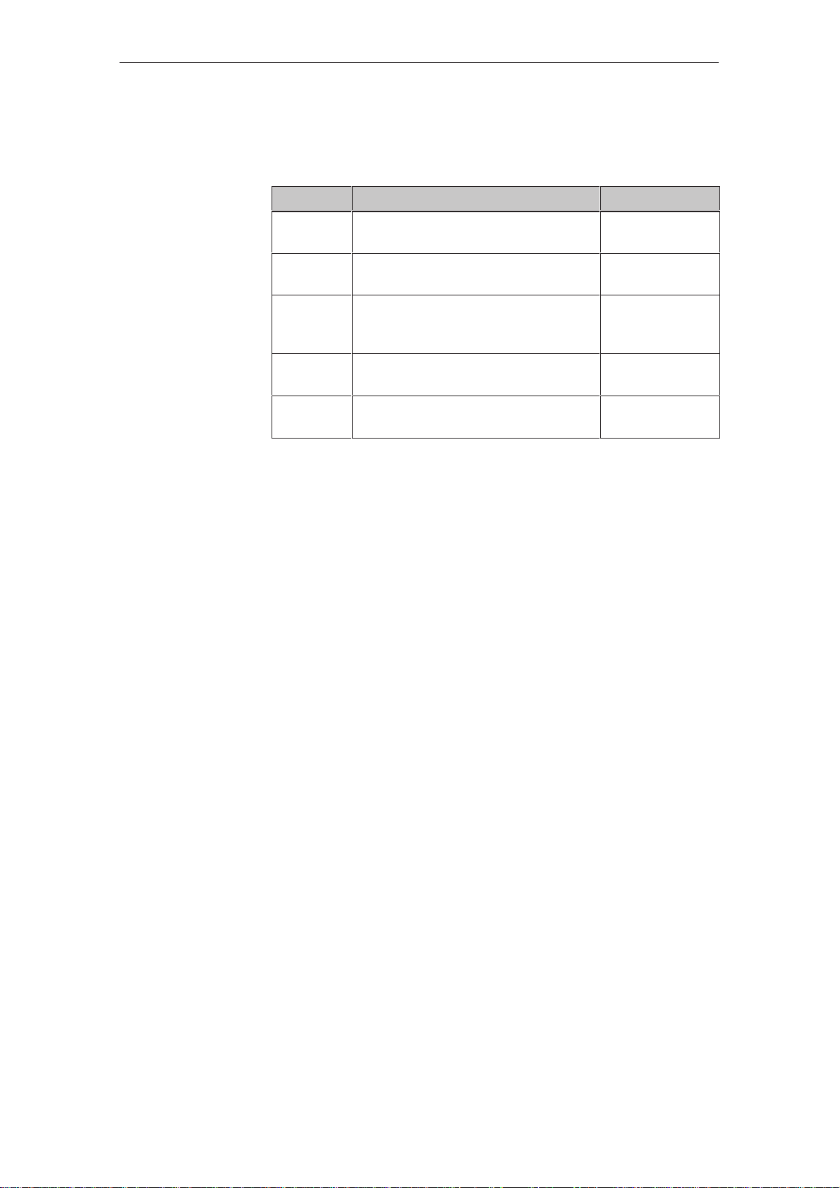
The equipment manual Touch Panel TP27, TP37 is organized into five parts:
Part Chapters Contents
I 1 - 2 Overview of the Touch Panel and range of
functions in tabular form.
II 3 - 11 Step-by-step instructions on how to operate the
Touch Panel using the standard screens.
III 12 - 13 – Mechanical and electrical installation,
– Commissioning
– Touch Panel operating modes.
IV 14 - 18 Detailed information on the Touch Panel and
maintenance.
V Appendix – Technical data,
– Interface assignments,
– System messages,
– SIMATIC HMI documentation,
– ESD guidelines,
– Glossary of technical terms.
Conventions
TP27, TP37 Equipment Manual
Release 01/00
The following conventions are used throughout this manual:
Motor off Text in the Touch Panel display is presented in this
typewriter font.
Variable
Screens Functions selected by the user are presented in this
ESC The labels of buttons are presented in a different
Symbolic names representing variable values on the
screen are presented in this italic typewriter font
standard italic font.
typeface.
i
Preface
History
The various releases of the equipment manual correspond to the following
firmware and ProTool versions:
Release Remarks ProTool version
04/97 First release of the TP37 equipment
V 3.0 and later
manual
10/97 Inclusion of TP27,
inclusion of touch screen functionality
09/98 Inclusion of the TP27–10;
V 4.0 and later
V 4.0 and later
V 5.0
new standard screen for printing
messages
01/99 Inclusion of standard screens for
V 5.1
Status/Force and Clean Screen
01/00 Inclusion of the JEIDA/PCMCIA card
V 5.2
for the TP27–6.
ii
TP27, TP37 Equipment Manual
Release 01/00

Preface
Other support
In the case of technical queries, please contact your local Siemens in the subsidiaries and branches responsible for your area.
SIMATIC Customer Support Hotline
Available worldwide, at all times:
Johnson City
Nuernberg
Singapur
Simatic Basic Hotline
Nuernberg
SIMA TIC BASIC Hotline
Local time:
Mon - Fri 8:00 to 18:00
T elephone:
+49 (911) 895-7000
Fax: +49 (911) 895-7002
E-Mail: simatic.support@
nbgm.siemens.de
SIMA TIC Premium Hotline
(charged, only with
SIMA TIC Card)
Time:
Mon - Fri 0:00 to 24:00
T elephone:
+49 (911) 895-7777
Fax:
+49 (911) 895-7001
Johnson City
SIMA TIC BASIC Hotline
Local time:
Mon - Fri 8:00 to 17:00
T elephone:
+1 423 461-2522
Fax: +1 423 461-2231
E-Mail: simatic.hotline@
sea.siemens.com
Singapur
SIMA TIC BASIC Hotline
Local time:
Mon - Fri 8:00 to 17:30
T elephone:
+65 740-7000
Fax: +65 740-7001
E-Mail: simatic@
singnet.com.sg
TP27, TP37 Equipment Manual
Release 01/00
iii

Preface
SIMATIC Customer Online Services
SIMATIC Customer Support offers comprehensive additional information concerning
SIMATIC products through its Online services as follows:
S Up–to–date general information is provided
– in Internet under http://www.ad.siemens.de/simatic
– via Fax-Polling under 08765-93 02 77 95 00
S Up–to–date product information and downloads for practical use can be found:
– in Internet unter http://www.ad.siemens.de/support/
html–00/
– via the Bulletin Board System (BBS) in Nürnberg (SIMATIC Custo-
mer Support Mailbox) under +49 (911) 895–7100
In order to contact the mailbox, please use a modem with up to 28.8
kBaud (V.34) capacity. Set the parameters as follows: 8, N, 1, ANSI,
or dial for connection via ISDN (x.75, 64 kBit).
Abbreviations
The abbreviations used in this equipment manual have the following
meaning:
AM Alarm Message
ANSI American National Standards Institute
AS511 Protocol of the PU interface to SIMATIC S5
ASCII American Standard Code for Information Interchange
CPI Control Panel Interface
CPU Central Processing Unit
DIL Dual-In-Line (package)
DP Decentral Periphery
DRAM Dynamic Random Access Memory
DKM Direct Key Module
EM Event message
ESD Electrostatic Sensitive Device
LCD Liquid Crystal Display
LED Light–Emitting Diode
MPI Multipoint Interface (SIMATIC S7)
PC
PLC
Personal Computer
Programmable Logic Controller
PU Programming Unit
PPI Point to Point Interface (SIMATIC S7)
SRAM Static Random Access Memory
STN Super Twisted Nematic
TFT Thin Film Transistor
TP Touch Panel
TTL Transistor-Transistor Logic
iv
TP27, TP37 Equipment Manual
Release 01/00

Contents
Part I INTRODUCTION
1 Product Description 1-1. . . . . . . . . . . . . . . . . . . . . . . . . . . . . . . . . . . . . . . . . . . . . . . . . . . .
1.1 Visualizing and Controlling Processes 1-3. . . . . . . . . . . . . . . . . . . . . . . . . . . . . .
1.2 The Touch Panels at a Glance 1-5. . . . . . . . . . . . . . . . . . . . . . . . . . . . . . . . . . . .
2 Functionality 2-1. . . . . . . . . . . . . . . . . . . . . . . . . . . . . . . . . . . . . . . . . . . . . . . . . . . . . . . . . . .
Part II FUNCTIONS OF THE TOUCH PANELS
3 General Operation 3-1. . . . . . . . . . . . . . . . . . . . . . . . . . . . . . . . . . . . . . . . . . . . . . . . . . . . . .
3.1 Operating Touch Elements 3-4. . . . . . . . . . . . . . . . . . . . . . . . . . . . . . . . . . . . . . . .
3.2 Entering Values 3-6. . . . . . . . . . . . . . . . . . . . . . . . . . . . . . . . . . . . . . . . . . . . . . . . .
3.2.1 Entering Numerical Values 3-6. . . . . . . . . . . . . . . . . . . . . . . . . . . . . . . . . . . . . . . .
3.2.2 Entering Alphanumeric Values 3-8. . . . . . . . . . . . . . . . . . . . . . . . . . . . . . . . . . . .
3.2.3 Entering Symbolic Values 3-10. . . . . . . . . . . . . . . . . . . . . . . . . . . . . . . . . . . . . . . .
3.3 Help Text 3-11. . . . . . . . . . . . . . . . . . . . . . . . . . . . . . . . . . . . . . . . . . . . . . . . . . . . . . .
4 Screens 4-1. . . . . . . . . . . . . . . . . . . . . . . . . . . . . . . . . . . . . . . . . . . . . . . . . . . . . . . . . . . . . . . .
4.1 Screen Elements 4-1. . . . . . . . . . . . . . . . . . . . . . . . . . . . . . . . . . . . . . . . . . . . . . . .
4.2 Standard Screens 4-3. . . . . . . . . . . . . . . . . . . . . . . . . . . . . . . . . . . . . . . . . . . . . . .
5 Password Protection 5-1. . . . . . . . . . . . . . . . . . . . . . . . . . . . . . . . . . . . . . . . . . . . . . . . . . .
5.1 Password Level and Access Permissions 5-1. . . . . . . . . . . . . . . . . . . . . . . . . . .
5.2 Login/Logout on the Touch Panel 5-3. . . . . . . . . . . . . . . . . . . . . . . . . . . . . . . . . .
5.3 Password Management 5-5. . . . . . . . . . . . . . . . . . . . . . . . . . . . . . . . . . . . . . . . . .
6 Messages 6-1. . . . . . . . . . . . . . . . . . . . . . . . . . . . . . . . . . . . . . . . . . . . . . . . . . . . . . . . . . . . . .
6.1 Types of Message 6-2. . . . . . . . . . . . . . . . . . . . . . . . . . . . . . . . . . . . . . . . . . . . . . .
6.1.1 Event Messages and Alarm Messages 6-2. . . . . . . . . . . . . . . . . . . . . . . . . . . . .
6.1.2 Alarm Messages 6-6. . . . . . . . . . . . . . . . . . . . . . . . . . . . . . . . . . . . . . . . . . . . . . . .
6.1.3 System Messages 6-8. . . . . . . . . . . . . . . . . . . . . . . . . . . . . . . . . . . . . . . . . . . . . . .
6.2 Displaying Messages 6-9. . . . . . . . . . . . . . . . . . . . . . . . . . . . . . . . . . . . . . . . . . . .
6.2.1 Opening a Message Page 6-11. . . . . . . . . . . . . . . . . . . . . . . . . . . . . . . . . . . . . . . .
6.2.2 Opening a Message Buffer 6-13. . . . . . . . . . . . . . . . . . . . . . . . . . . . . . . . . . . . . . .
6.3 Deleting Messages 6-14. . . . . . . . . . . . . . . . . . . . . . . . . . . . . . . . . . . . . . . . . . . . . .
TP27, TP37 Equipment Manual
Release 01/00
i

Contents
6.4 Printing Messages 6-16. . . . . . . . . . . . . . . . . . . . . . . . . . . . . . . . . . . . . . . . . . . . . . .
6.5 ALARM_S Messages 6-18. . . . . . . . . . . . . . . . . . . . . . . . . . . . . . . . . . . . . . . . . . . .
6.5.1 Communication Sequence 6-19. . . . . . . . . . . . . . . . . . . . . . . . . . . . . . . . . . . . . . . .
6.5.2 Message Acknowledgement 6-20. . . . . . . . . . . . . . . . . . . . . . . . . . . . . . . . . . . . . .
6.5.3 Printing Messages 6-20. . . . . . . . . . . . . . . . . . . . . . . . . . . . . . . . . . . . . . . . . . . . . . .
6.5.4 Message Overload 6-21. . . . . . . . . . . . . . . . . . . . . . . . . . . . . . . . . . . . . . . . . . . . . .
6.5.5 Updating 6-22. . . . . . . . . . . . . . . . . . . . . . . . . . . . . . . . . . . . . . . . . . . . . . . . . . . . . . .
6.5.6 Buffer Overflow 6-23. . . . . . . . . . . . . . . . . . . . . . . . . . . . . . . . . . . . . . . . . . . . . . . . .
6.6 Standard Screens for Messages 6-24. . . . . . . . . . . . . . . . . . . . . . . . . . . . . . . . . . .
6.6.1 “Edit Message” Standard Screen 6-24. . . . . . . . . . . . . . . . . . . . . . . . . . . . . . . . . .
6.6.2 “Output Messages” Standard Screen 6-26. . . . . . . . . . . . . . . . . . . . . . . . . . . . . . .
6.6.3 “System Settings” Standard Screen 6-28. . . . . . . . . . . . . . . . . . . . . . . . . . . . . . . .
7 Printing 7-1. . . . . . . . . . . . . . . . . . . . . . . . . . . . . . . . . . . . . . . . . . . . . . . . . . . . . . . . . . . . . . . .
8 Recipes 8-1. . . . . . . . . . . . . . . . . . . . . . . . . . . . . . . . . . . . . . . . . . . . . . . . . . . . . . . . . . . . . . . .
8.1 Standard Screens for Recipes 8-3. . . . . . . . . . . . . . . . . . . . . . . . . . . . . . . . . . . .
8.1.1 Creating, Editing and Saving Data Records 8-8. . . . . . . . . . . . . . . . . . . . . . . . .
8.1.2 Transferring Data Records 8-13. . . . . . . . . . . . . . . . . . . . . . . . . . . . . . . . . . . . . . . .
8.2 Record Sets 8-15. . . . . . . . . . . . . . . . . . . . . . . . . . . . . . . . . . . . . . . . . . . . . . . . . . . .
9 Storing and Loading Data 9-1. . . . . . . . . . . . . . . . . . . . . . . . . . . . . . . . . . . . . . . . . . . . . . .
9.1 Data Types, Data Media and Storage Principle 9-1. . . . . . . . . . . . . . . . . . . . . .
9.2 Delete Storage Medium 9-3. . . . . . . . . . . . . . . . . . . . . . . . . . . . . . . . . . . . . . . . . .
9.3 Backup/Restore 9-5. . . . . . . . . . . . . . . . . . . . . . . . . . . . . . . . . . . . . . . . . . . . . . . . .
10 Status/Force Variable Using the TP 10-1. . . . . . . . . . . . . . . . . . . . . . . . . . . . . . . . . . . . . .
10.1 Status Variable 10-2. . . . . . . . . . . . . . . . . . . . . . . . . . . . . . . . . . . . . . . . . . . . . . . . . .
10.2 Force Variable 10-5. . . . . . . . . . . . . . . . . . . . . . . . . . . . . . . . . . . . . . . . . . . . . . . . . .
11 System Settings 11-1. . . . . . . . . . . . . . . . . . . . . . . . . . . . . . . . . . . . . . . . . . . . . . . . . . . . . . . .
11.1 Setting an Operating Mode 11-4. . . . . . . . . . . . . . . . . . . . . . . . . . . . . . . . . . . . . . .
11.2 Blanking the Screen 11-5. . . . . . . . . . . . . . . . . . . . . . . . . . . . . . . . . . . . . . . . . . . . .
11.3 Deactivate Touch Screen 11-6. . . . . . . . . . . . . . . . . . . . . . . . . . . . . . . . . . . . . . . . .
11.4 Calibrating the Touch Screen (TP37 and TP27-10 only) 11-7. . . . . . . . . . . . . . .
11.5 Other Settings 11-8. . . . . . . . . . . . . . . . . . . . . . . . . . . . . . . . . . . . . . . . . . . . . . . . . .
Part III INSTALLATION AND COMMISSIONING
12 Installation 12-1. . . . . . . . . . . . . . . . . . . . . . . . . . . . . . . . . . . . . . . . . . . . . . . . . . . . . . . . . . . . .
12.1 Mechanical Installation 12-2. . . . . . . . . . . . . . . . . . . . . . . . . . . . . . . . . . . . . . . . . . .
12.2 Electrical Installation 12-6. . . . . . . . . . . . . . . . . . . . . . . . . . . . . . . . . . . . . . . . . . . . .
12.2.1 Power Supply and Relay Contacts 12-7. . . . . . . . . . . . . . . . . . . . . . . . . . . . . . . . .
12.2.2 Connecting the Configuration Computer 12-8. . . . . . . . . . . . . . . . . . . . . . . . . . . .
12.2.3 Connecting the PLC 12-10. . . . . . . . . . . . . . . . . . . . . . . . . . . . . . . . . . . . . . . . . . . . .
12.2.4 Connecting a Printer 12-12. . . . . . . . . . . . . . . . . . . . . . . . . . . . . . . . . . . . . . . . . . . . .
ii
TP27, TP37 Equipment Manual
Release 01/00

Contents
13 Commissioning 13-1. . . . . . . . . . . . . . . . . . . . . . . . . . . . . . . . . . . . . . . . . . . . . . . . . . . . . . . .
13.1 Initial Startup 13-3. . . . . . . . . . . . . . . . . . . . . . . . . . . . . . . . . . . . . . . . . . . . . . . . . . .
13.2 Recommissioning 13-4. . . . . . . . . . . . . . . . . . . . . . . . . . . . . . . . . . . . . . . . . . . . . . .
13.3 Startup Behavior 13-8. . . . . . . . . . . . . . . . . . . . . . . . . . . . . . . . . . . . . . . . . . . . . . . .
13.4 Testing a Configuration in OFFLINE Mode 13-9. . . . . . . . . . . . . . . . . . . . . . . . . .
13.5 Testing the Configuration in Conjunction with the PLC 13-10. . . . . . . . . . . . . . . .
Part IV DEVICE DESCRIPTION AND MAINTENANCE
14 Unit Description TP27-6 14-1. . . . . . . . . . . . . . . . . . . . . . . . . . . . . . . . . . . . . . . . . . . . . . . . .
14.1 Dimensions 14-1. . . . . . . . . . . . . . . . . . . . . . . . . . . . . . . . . . . . . . . . . . . . . . . . . . . . .
14.2 Operating elements 14-2. . . . . . . . . . . . . . . . . . . . . . . . . . . . . . . . . . . . . . . . . . . . . .
14.3 Connection elements 14-2. . . . . . . . . . . . . . . . . . . . . . . . . . . . . . . . . . . . . . . . . . . .
14.4 Communication options 14-3. . . . . . . . . . . . . . . . . . . . . . . . . . . . . . . . . . . . . . . . . .
15 Unit Description TP27-10 15-1. . . . . . . . . . . . . . . . . . . . . . . . . . . . . . . . . . . . . . . . . . . . . . . .
15.1 Dimensions 15-2. . . . . . . . . . . . . . . . . . . . . . . . . . . . . . . . . . . . . . . . . . . . . . . . . . . . .
15.2 Operating elements 15-3. . . . . . . . . . . . . . . . . . . . . . . . . . . . . . . . . . . . . . . . . . . . . .
15.3 Connection Elements 15-3. . . . . . . . . . . . . . . . . . . . . . . . . . . . . . . . . . . . . . . . . . . .
15.4 Communication options 15-4. . . . . . . . . . . . . . . . . . . . . . . . . . . . . . . . . . . . . . . . . .
16 Unit Description TP37 16-1. . . . . . . . . . . . . . . . . . . . . . . . . . . . . . . . . . . . . . . . . . . . . . . . . . .
16.1 Dimensions 16-2. . . . . . . . . . . . . . . . . . . . . . . . . . . . . . . . . . . . . . . . . . . . . . . . . . . . .
16.2 Operating and Display Elements 16-3. . . . . . . . . . . . . . . . . . . . . . . . . . . . . . . . . .
16.3 Connection Elements 16-5. . . . . . . . . . . . . . . . . . . . . . . . . . . . . . . . . . . . . . . . . . . .
16.4 Communication options 16-6. . . . . . . . . . . . . . . . . . . . . . . . . . . . . . . . . . . . . . . . . .
17 Options 17-1. . . . . . . . . . . . . . . . . . . . . . . . . . . . . . . . . . . . . . . . . . . . . . . . . . . . . . . . . . . . . . . .
17.1 Direct Key Module 17-1. . . . . . . . . . . . . . . . . . . . . . . . . . . . . . . . . . . . . . . . . . . . . . .
17.1.1 Installing the Direct Key Module 17-2. . . . . . . . . . . . . . . . . . . . . . . . . . . . . . . . . . .
17.1.2 Connectors and Adjusters 17-4. . . . . . . . . . . . . . . . . . . . . . . . . . . . . . . . . . . . . . . .
17.2 Control Panel Interface 17-6. . . . . . . . . . . . . . . . . . . . . . . . . . . . . . . . . . . . . . . . . . .
17.2.1 Installing the Control Panel Interface 17-7. . . . . . . . . . . . . . . . . . . . . . . . . . . . . . .
17.2.2 Connectors 17-9. . . . . . . . . . . . . . . . . . . . . . . . . . . . . . . . . . . . . . . . . . . . . . . . . . . . .
18 Maintenance/Upkeep 18-1. . . . . . . . . . . . . . . . . . . . . . . . . . . . . . . . . . . . . . . . . . . . . . . . . . . .
18.1 Cleaning the Screen 18-1. . . . . . . . . . . . . . . . . . . . . . . . . . . . . . . . . . . . . . . . . . . . .
18.2 Replacing the Backup Battery 18-2. . . . . . . . . . . . . . . . . . . . . . . . . . . . . . . . . . . . .
18.3 Replacing the Back–Lighting (TP37 only) 18-4. . . . . . . . . . . . . . . . . . . . . . . . . . .
TP27, TP37 Equipment Manual
Release 01/00
iii

Contents
Part V APPENDICES
A Technical Data A-1. . . . . . . . . . . . . . . . . . . . . . . . . . . . . . . . . . . . . . . . . . . . . . . . . . . . . . . . .
A.1 Direct Key Module and Control Panel Interface A-5. . . . . . . . . . . . . . . . . . . . . .
A.2 Chemical Resistance of the Touch Panel A-8. . . . . . . . . . . . . . . . . . . . . . . . . . .
B Interface Assignments B-1. . . . . . . . . . . . . . . . . . . . . . . . . . . . . . . . . . . . . . . . . . . . . . . . . .
C System Messages C-1. . . . . . . . . . . . . . . . . . . . . . . . . . . . . . . . . . . . . . . . . . . . . . . . . . . . . .
D SIMATIC HMI Documentation D-1. . . . . . . . . . . . . . . . . . . . . . . . . . . . . . . . . . . . . . . . . . . .
E ESD Guidelines E-1. . . . . . . . . . . . . . . . . . . . . . . . . . . . . . . . . . . . . . . . . . . . . . . . . . . . . . . .
Glossary Glossary-1. . . . . . . . . . . . . . . . . . . . . . . . . . . . . . . . . . . . . . . . . . . . . . . . . . . . . . . . . . .
Index Index-1. . . . . . . . . . . . . . . . . . . . . . . . . . . . . . . . . . . . . . . . . . . . . . . . . . . . . . . . . . . . . . . . .
iv
TP27, TP37 Equipment Manual
Release 01/00

INTRODUCTION
1 Product Description
2 Functionality
Part I

-2
TP27, TP37 Equipment Manual
Release 01/00

Product Description
1
Use of TP27 and
TP37
Touch screen
By implementing the T ouch Panels TP27 and TP37 operating statuses, current
process values and faults in respect of a connected PLC can be graphically
represented and the monitoring machine or system easily operated. This is
made possible by using the T ouch Panels which have of a number of standard
functions for this purpose.
The method of display and operation of the T ouch Panel can be customized
using the ProT ool configuration software to achieve optimum results in respect
of process requirements.
The Touch Panel can be used to
S control and monitor the process by means of the menu system. In this way,
setpoints can be entered in the form of values or by touching configured
buttons, for example, or control positioning elements;
S display processes, machines and systems on full–graphic and semi–graphic
screens;
S visualize event messages and alarm messages, in addition to process
variables such as an output field, bar graph, trends or status display;
S intervene directly in the operation by means of the touch–sensitive screen.
The Touch Panels TP27 and TP37 have standard keyboards. The device is
operated intuitively by touching configured buttons and input fields on the
touch–sensitive screen, referred to in this manual as the “touch screen”.
Device variants
Installation
possibilities
TP27, TP37 Equipment Manual
Release 01/00
The TP27 can be supplied in a range of variations. One variant is equipped
with a 6 inch display, available as monochrome and color versions. This
variant is subsequently referred to as TP27-6.
The second variant is the TP27, equipped with a 10 inch, color display. This
variant is subsequently referred to as TP27-10.
The TP37 is equipped with a 10 inch, color display.
The T ouch Panels TP27 and TP37 are installation units for use directly at the
machine location. The degree of protection is high (front panel IP65), so the
devices are suitable for use in hostile industrial environments.
1-1
Product Description
Set up data areas
Configuration
using ProTool
Before commissioning, the Touch Panel must be prepared for the task of
visualizing data from the PLC. This means that data areas must be created in
the PLC memory in your configuration which are then used by the T ouch Panel
to communicate with the PLC.
Graphics and texts to be displayed on the T ouch Panel, together with the
properties and functionalities of the touch–sensitive operating elements, must
be created beforehand by means of a configuration computer (PC or PG) using
the configuration software ProT ool. Before downloading the configuration data
to the T ouch Panel, connect the configuration computer to the Touch Panel.
Once the configuration has been successfully downloaded, connect the T ouch
Panel to the PLC. The T ouch Panel now communicates with the PLC and
reacts to program execution on the PLC in accordance with the configured default values.
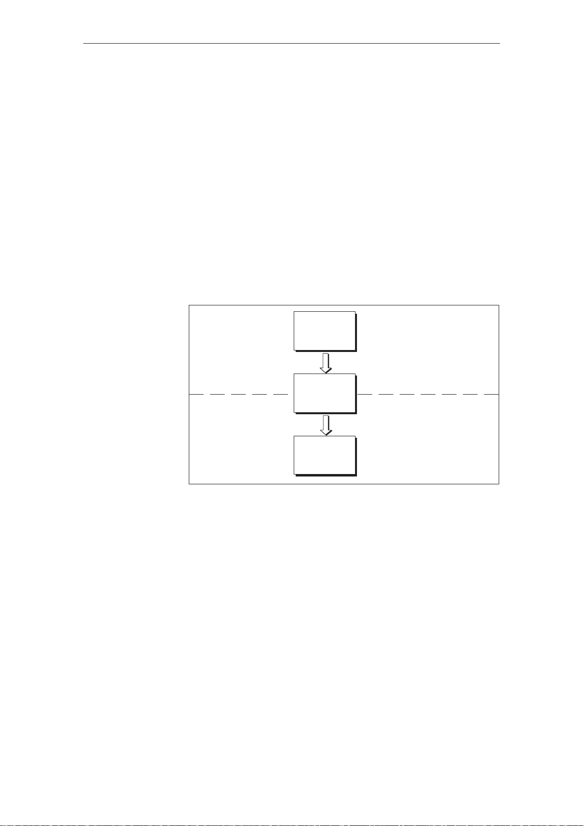
Figure 1-1 outlines the configuration and process control phase.
Configuration phase
PC or PU
Create configuration data
Save configuration data
Download configuration data
Further
information
Touch Panel
Connected to PLC
Process control phase
Figure 1-1 Configuration and process control phase
PLC
Information regarding configuration of the T ouch Panel is provided in the
User’s Guide ProTool – Configuring Graphics Displays.
The Communication User’ s Guide provides information on connecting the
T ouch Panel to the PLC.
1-2
TP27, TP37 Equipment Manual
Release 01/00

1.1 Visualizing and Controlling Processes
Product Description
Display and
operating
functions
Screens
The basic function of the T ouch Panels TP27 and TP37 is the visualization of
process statuses and the operation of processes. The following display and
operating functions can be configured:
S screens
S input/output of process values
S bar graphs and trends
S text or graphic lists
S messages
S printout
S text
S help text
S recipes
S multiple languages
S password protection
S touch–sensitive operating elements.
Logically related process data from the PLC can be compiled, displayed on a
screen and individual parts of it modified. Screens may contain buttons,
graphics, text and values.
The Touch Panels can display machines and systems as full–graphics scr eens .
This makes it easier for the operator to find his way around.
Input/Output
Bar graphs and
trend curves
Symbol lists
TP27, TP37 Equipment Manual
Release 01/00
Numeric, alphanumeric and symbolic values can be entered via touch–sensitive
input fields on the T ouch Panel which are then transferred to the PLC. Current
values of the PLC are displayed in output fields.
Current process values can be output as numeric values, symbolic text,
symbolic graphs or in the form of bar graphs and trend curves.
S Bar graphs
represent a value as a rectangular area. Bar graphs can be used to display
fill levels or quantities, for example.
S Trends
display a value continuously. This display mode is useful when displaying
values that vary with time, variations in temperature or pressure,
for example.
Various graphic elements (bitmaps) or texts can be called into the display
depending on the process status. In this way, for example, the current setting of
a valve can be visualized on the T ouch Panel by means of symbolic graphics
or text can be modified according to the situation.
1-3

Product Description
Messages
Recording
T exts
Help texts
Messages appear on the Touch Panel in plain text. The message text may also
contain current process values. Incoming messages are stored in a message
buffer together with their date and time.
S Event messages
provide information and operating notes on current processes or machine
states, for example
Motor running at 3000 revs.
S Alarm messages
provide information on critical machine states, for example
Motor speed too high.
Alarm messages must be acknowledged on account of their urgency.
Messages are classified as event messages or alarm messages during configuration.
All message events can be additionally recorded by being printed out in online
mode on a connected printer. Messages which have accumulated in the event
and alarm buffers can also be printed out.
T exts identify individual parts of the screen in order to be able to assign the
fields displayed to the process.
Help texts represent additional information and notes for the operator, which
can be configured, in respect of the screens, input fields and messages. The
help text relating to an alarm message, for example, may display information
on the cause of a malfunction and how to clear it.
Recipe
Multiple languages
Password
protection
Operating
elements
Complete machine data records can be stored as recipes in a T ouch Panel. A
recipe defines the data structure in a configuration. Data is assigned to the
configured structure on the T ouch Panel.
The purpose of recipes is to transfer several items of data collectively to the
PLC. In this respect, it is immaterial whether actual recipes, specifications of
quantities, distances to be traversed or temperature variations are involved.
Message texts, texts in screens, help texts, system messages and button labels
may be stored in three languages simultaneously in the T ouch Panel and
selected online.
The password protection feature prevents unauthorized operations of the T ouch
Panel. Different passwords can be assigned to different users or user groups,
thus authorizing or prohibiting access to specific control functions by assigning
different password levels.
Direct intervention in the process operation is possible by using the
touch–sensitive buttons and input fields on the T ouch Panel screen.
The structure of the T ouch Panel user interface can be configured to suit individual needs. Simply adjust the number, characteristics, positions and functionality of the operating elements for the specific application.
1-4
TP27, TP37 Equipment Manual
Release 01/00
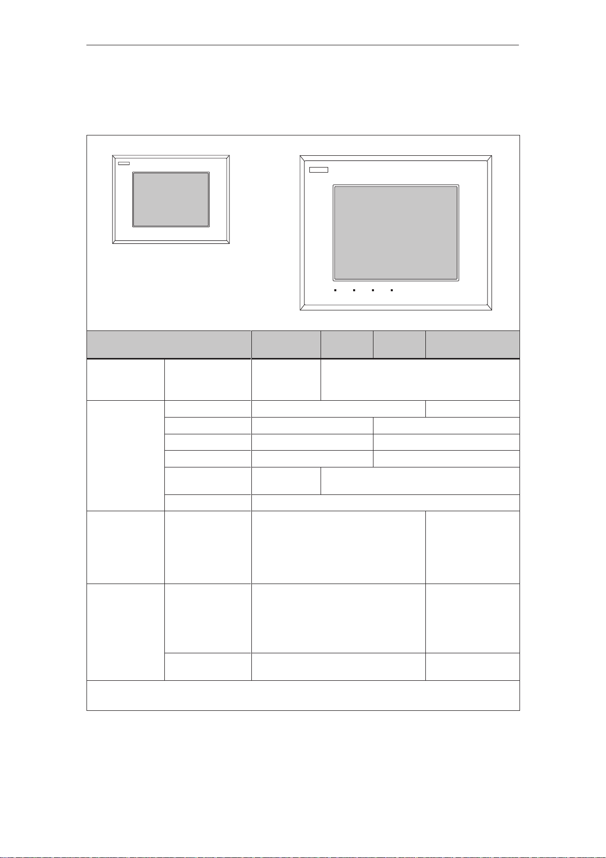
1.2 The Touch Panels at a Glance
Product Description
SIMATIC TP27
Hardware TP27-6
Models Monochrome
Monochrome
4
TP27-6
Color
TP27-10
Color
SIMATIC TP37
TP37
Color
–
display
Display
Color display
–
Type STN1)-LCD TFT2)-LCD
4
Size 5.7” 10.3”
Touch screen Matrix 20 x 15 Analog, resistive
Resolution (pixels) 320 x 240 640 x 480
Colors 8
8
Grey shades
Back–lighting 4
Indicators LEDs for – TP on
Temperature limit
value reached
Write/read access to
memory card
Interfaces
Serial interface to
connection
From PLC,
PC/PU, printer
2 x RS232/TTY
(active/passive)
1 x RS422/RS485
2 x RS232/TTY
(active/passive)
1 x RS422/RS485
1 x TTY (passive) /
RS422/RS485
Parallel interface for
– 1 x TTL (Centronics)
connecting a printer
1)
passive drive
2)
active drive
TP27, TP37 Equipment Manual
Release 01/00
1-5
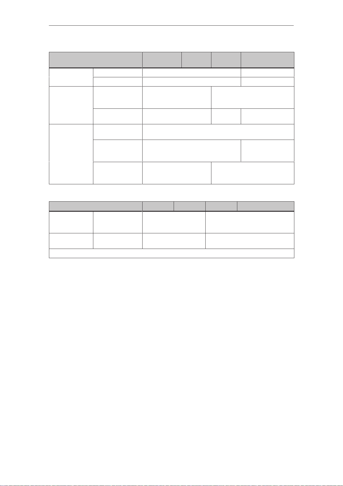
Product Description
Processor
Memory
Special features
direct key module
Hardware
TP27-6
Monochrome
TP27-6
Color
TP27-10
Color
TP37
Color
Type 80486 Pentium
Clock 33 MHz 100 MHz
Flash EPROM for
firmware and user
1 MB 2 MB
data
Main memory
2 MB 4 MB 8 MB
(DRAM)
Hardware clock
4
(battery–backed)
Relay output for
– 4
temperature monitoring
Module slot for
PCMCIA/Jeida
cards
4 Slot B
(Slot A not used)
Hardware TP27M-6 TP27C-6 TP27-10 TP37
Digital outputs,
8 16
drive via
configurable ports
Control Panel
Interface
1)
1)
usable only in conjunction with SIMATIC S7 and Profibus-DP
Further
information
Digital inputs/outputs
Detailed information regarding the technical data of the Touch Panels TP27
and TP37 is provided in the Appendix A of this manual.
16 16/32
1-6
TP27, TP37 Equipment Manual
Release 01/00
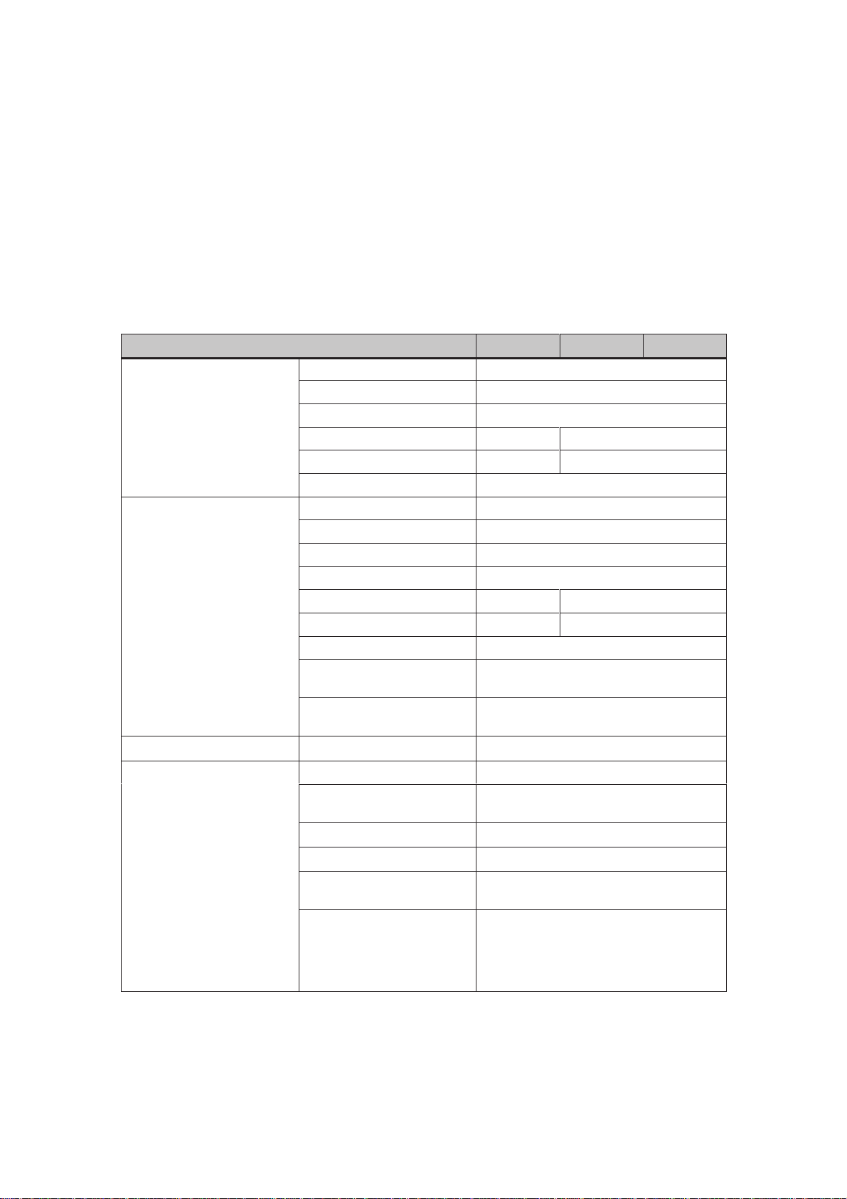
Functionality
The table below summarizes the functions of the T ouch Panels TP27 and TP37. The values quoted are the
maximum values which can be managed by the T ouch Panels. The values are limited by the size of the
user memory.
Functions TP27-6 TP27-10 TP37
Event messages
Alarm messages
Message logging Output to printer
Message buffer
Number 2000
Display On message line/message window
View all waiting messages on message page
Length message text per line 35 characters 70 characters
Lines per message 2 1
Process values in message text 8
Number 2000
Display In message window
Display type First value/last value, selectable
View all waiting messages On message page
Length message text per line 35 characters 70 characters
Lines per message 2 1
Process values in message text 8
Acknowledge individual alarm
messages
Acknowledge several alarm
messages simultaneously
Capacity 512 message events
View buffered event/alarm
messages
Delete
Buffer overflow warning
Automatic printout on buffer
overflow
Message events queued
simultaneously (max.)
16 acknowledgment groups
S Event messages
S Alarm messages
4
4
4
4
4
4
500
250
2
TP27, TP37 Equipment Manual
Release 01/00
2-1
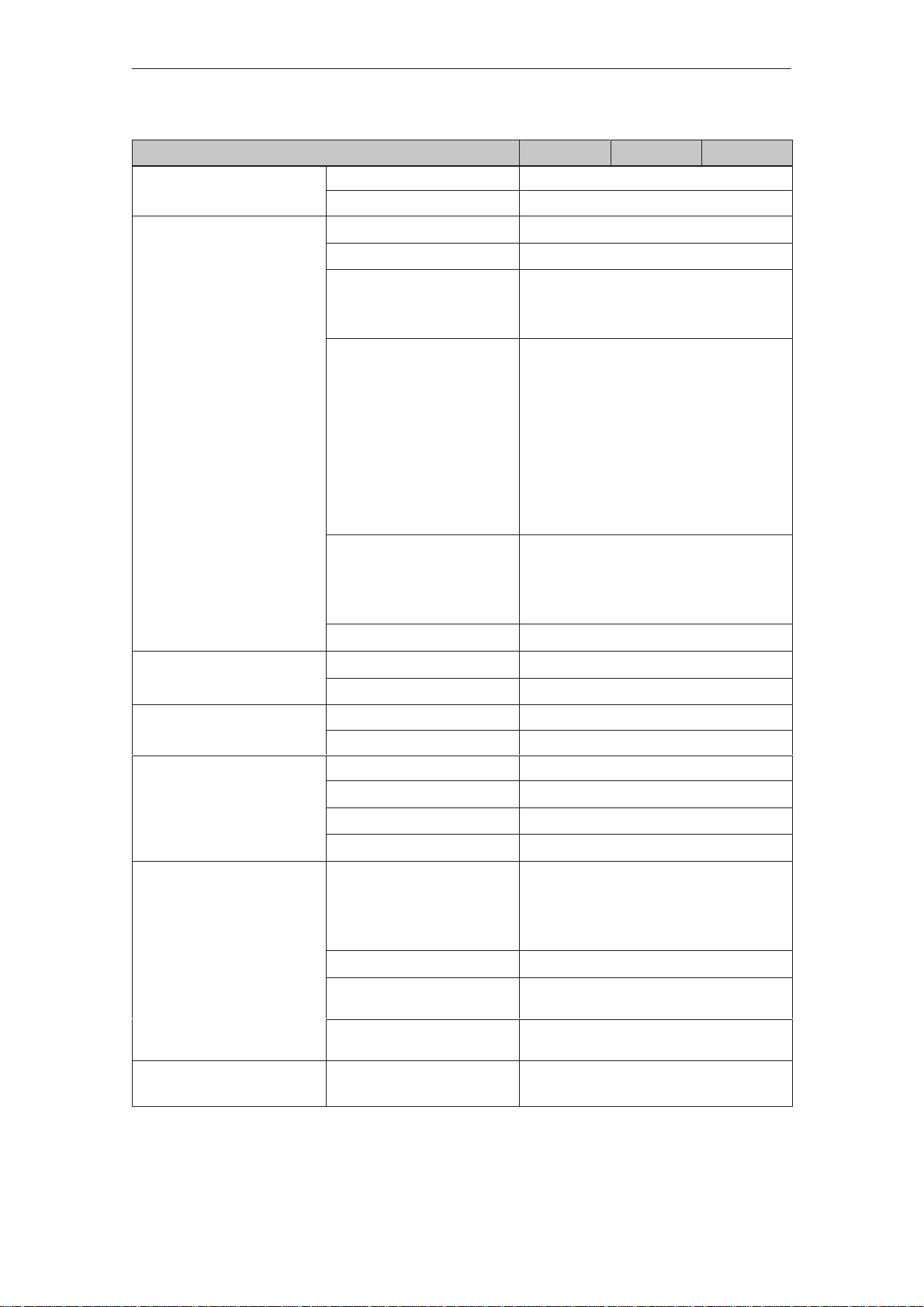
Functionality
Message acquisition
Screens
Limit value monitoring
Text attributes
Help text
Print functions Hardcopy of display contents
Time of occurrence Date and time
Message events Arrive, depart, acknowledge
View
Printout
Static screen elements Pixel graphics
Input/Output elements Input fields
Operator prompting Buttons (dynamically modifiable)
Fixed window
Inputs/outputs
Bar graphs and trends
Display Flashing, inverse, underscore
Printer (messages) Bold, underscore
Lines/characters 7/35
For messages
For input fields
For screens
(screen dump)
S character mode (ASCII)
S graphics mode
TP37TP27-10TP27-6Functions
4
4
Text
Character graphics
Output fields
Combined input/output fields
Symbolic input fields
Symbolic output fields
Bar graphs
Trends
Buttons
light indicators
light indicators
Symbolic input
Symbolic output
4
4
4
4
4
4
4
4
Direct message logging
Screen printout in character
mode (ASCII)
Graphics printout in graphics
mode
Password protection Number of passwords
Password levels
2-2
4
4
4
50
10 (0...9)
TP27, TP37 Equipment Manual
Release 01/00
Recipes
Number 255
Data records per recipe 500
Entries per data record 500
Save (create) data records PLCTP ! Data medium
Load data records Data medium ! TP/PLC
Delete data records On data medium
Modify (edit) data records On data medium
Transfer current values PLC ! TP
Transfer data records Data Medium ! TP
Record sets
Backup Backup/restore for memory
card
Online language change
Number of languages 3
Loadable character sets per
language
Language–independent charac-
ter set (incl. character–graphic
characters)
Character size in pixels 8 x 8 to 64 x 64
Display
Blank screen
Contrast
Audio volume adjustable
Calibration not necessary 4
1)
Can only be switched on/off
3000 (SIMATIC S7)
TP ! PLC
TP ! Data Medium
4
–
3
1
4
4 –
4 4
Functionality
TP37TP27-10TP27-6Functions
4
1)
TP27, TP37 Equipment Manual
Release 01/00
2-3

Functionality
Communication SIMATIC S5
– AS511 4
– FAP 4
– PROFIBUS-DP 4
SIMATIC S7/M7
– PPI 4
– MPI 4
– PROFIBUS-DP 4
SIMATIC 500/505
– NITP
NATIVE driver
– AEG/Modicon (Modbus)
– Allen Bradley (DF1)O
– Mitsubishi (FX)
– Omron
– Telemecanique (Adjust,
Uni-Telway)
TP37TP27-10TP27-6Functions
4
4
4
4
4
4
2-4
TP27, TP37 Equipment Manual
Release 01/00

FUNCTIONS OF THE
TOUCH PANELS
3 General Operation
4 Screens
5 Password Protection
6 Messages
7 Printing
8 Recipes
9 Storing and Loading Data
10 Status/Force Tag Using the TP
11 System Settings
Part II

2-2
TP27, TP37 Equipment Manual
Release 01/00

General Operation
3
Operating concept
Screen partitioning
Using the Touch Panel screen, it is possible to observe the operating status of
the machine or system being monitored and, at the same time, to intervene directly in the process running simply by touching the buttons and input fields
displayed.
Operation of the T ouch Panels TP27 and TP37 is intuitive to a large extent,
because
S operating elements can be positioned where they belong, from a functional
point of view,
S labeling of visible buttons is dynamic; in other words, labeling can be
changed online, according to the language required, or
language–independent bitmaps can be assigned to the buttons, for example,
S any sections of the system or process screen are rendered operable by su-
perimposing invisible buttons
S virtual keys for cursor functions and value input only appear when they can
actually be used: In input windows.
A screen occupies the entire display. An example of screen partitioning on the
TP37 display containing several open windows is illustrated in figure 3-1. The
TP27-6 has a smaller display, so that the operating elements are cascaded
(overlap).
System messages
Global button
TP27, TP37 Equipment Manual
Release 01/00
Light indicators
Figure 3-1 Screen partitioning on the TP37 (example)
Local button
Help window
Fixed window
Message indicators
Event and alarm
messages
Main area
Numeric input
window
3-1
General Operation
Fixed window
Main area
Buttons
The fixed window can be used to display important process magnitudes or date
and time, since the contents are not affected by the screen currently open.
The main area comprises the entire display. It is superimposed by all other
areas (fixed window, message window etc.). The main area contains the current
contents of the screen that is currently open.
The functions configured for the buttons have a local significance in the main
area. Buttons of local significance initiate different actions from screen to
screen on the T ouch Panel or on the PLC, such as enabling and disabling Select
Screen, Language Switch or message logging. If buttons are positioned in the
fixed window , their functions are available globally. This means, for example,
that the current screen can be printed (Print Screen) or the system returned to
the main screen from any operating situation.
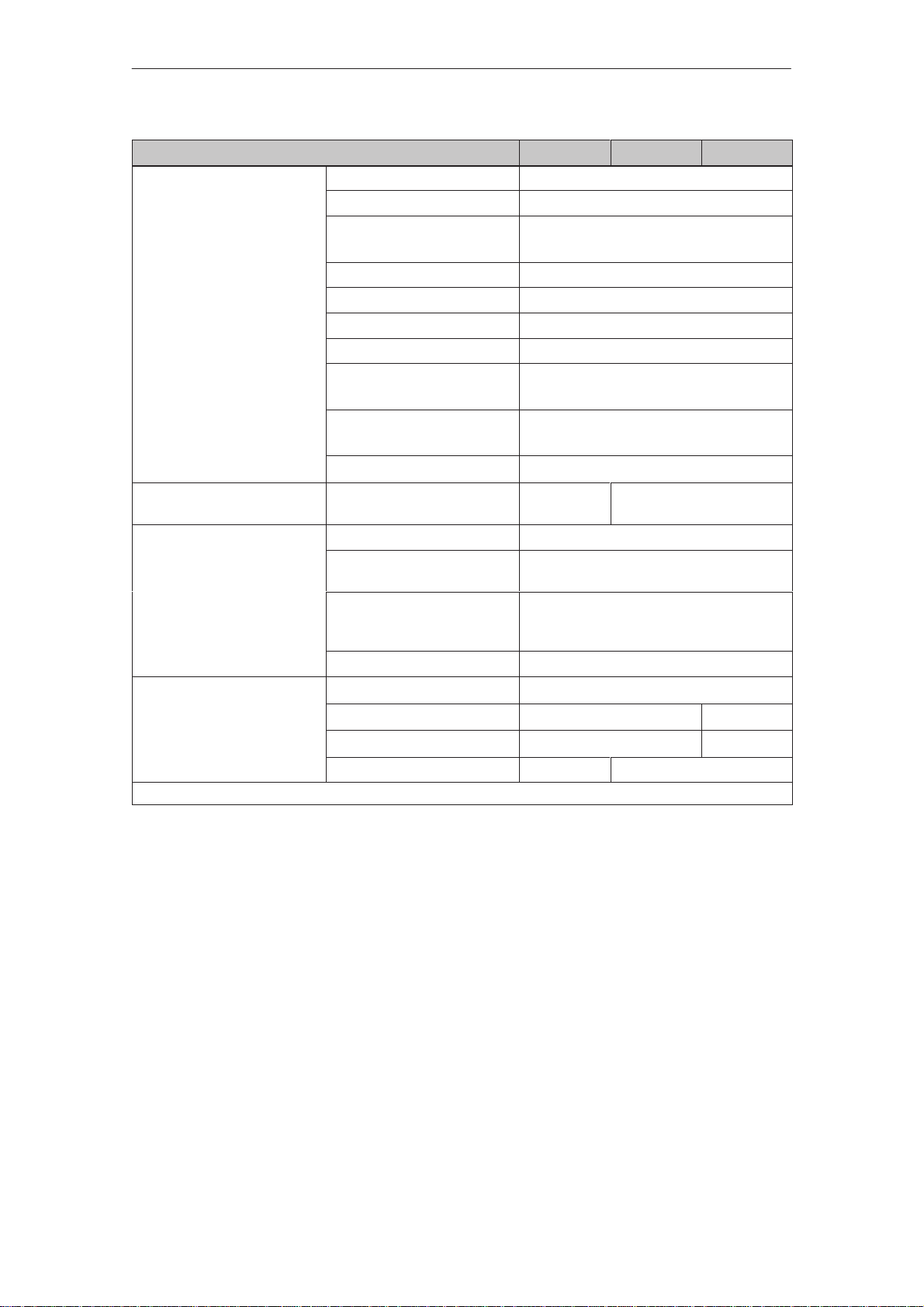
Buttons may have text or graphic labels. Examples:
Help
Light indicators
Light indicators are configurable, non–operable display elements. A light indicator signals the status of a defined bit by assigning dynamic attributes, for
example a change of color or flashing text.
No function is assigned to a light indicator. Light indicators have thin borders
to distinguish them from user–operable buttons.
Temperature
Light indicators can be positioned locally in the main area or globally in the
fixed window.
3-2
TP27, TP37 Equipment Manual
Release 01/00

General Operation
Window positions
Open windows
Message indicator
Input window:
Regardless of the absolute position of the selected field, the input window always appears at the bottom right of the screen. After clicking on the top edge
of the window, it skips to the opposite edge of the screen (only with TP37 and
TP27-10)
Message window:
The system message window appears in the upper part of the screen. The position of the event message window can be configured.
Help window:
The window for displaying configured Help texts is appears at the bottom left.
Several windows can be opened simultaneously on the T ouch Panel, e.g. an
input window in the main area, an event message window, an alarm window
and a help window (figure 3-1). As soon as one of these windows is opened,
the input elements in the main area and fixed window can no longer be
accessed. All visible elements in the input and message windows remain
accessible.
The message indicator indicates that alarm messages have been received.
Not flashing: Alarm messages have been received which have been
acknowledged.
Flashing: Alarm messages have been received which have not been
acknowledged.
TP27, TP37 Equipment Manual
Release 01/00
3-3

General Operation
3.1 Operating Touch Elements
Definition
Triggering
functions
Touch elements are contact–sensitive operating elements on the screen of the
T ouch Panel, such as buttons, input fields, message windows and help windows. Their operation is basically no different from pressing conventional
keys. T ouch elements are operated by lightly touching them with your finger or
a pointer.
Note
S Never use pointed or sharp instruments to operate the Touch Panel to pre-
vent damage to the plastic surface of the touch screen.
S Touch only one point of the Touch Panel screen at a time. Do not touch
several touch elements simultaneously. If you do, an unintended action
may be initiated.
A function assigned to a button is normally triggered when the button is
touched. With some functions, it is possible to define the configuration so that
the function is not triggered until the button is released or its outlines remain
while being touched, e.g. the “Set Bit” function or the keypad in the input
window for numerical values. If the button has a repeater, keep touching the
button as long as the function in question is to be to repeated.
Not more than one touch element is activated per touch. Where an operating
function has still not been completed, e.g. entering a value, any successive attempt to trigger a similar function is refused and a system message to this effect issued. Similar functions in this respect are Enter Setpoint and Edit Data
Record, for example.
Operation
acknowledgement
Acoustic
acknowledgment
3-4
When the T ouch Panel detects contact on a valid touch element, it responds
with a visual or acoustic acknowledgement. An acknowledgment is independent of communication with the PLC. It is not an indication of the required
action actually having been executed.
An acoustic signal is issued as long as the touch element is touched. The signal
tone can be enabled and disabled by means of the System Settings standard
screen (TP37) and the volume adjusted (TP27), see chapter 11.
TP27, TP37 Equipment Manual
Release 01/00

General Operation
Visual
acknowledgement
The type of visual operation acknowledgement is dependent on the operating
element touched.
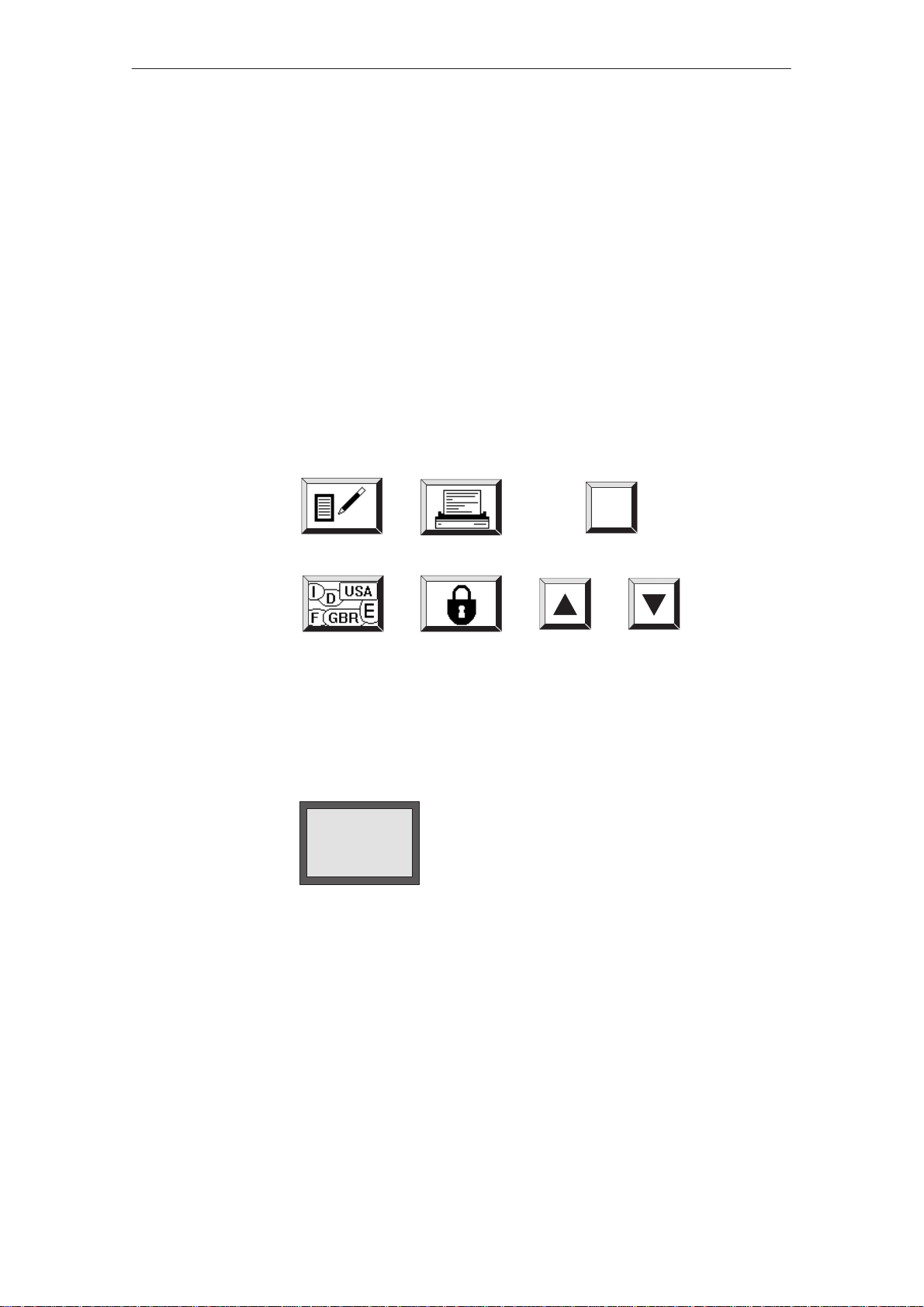
S Visible buttons
The border color of the button touched changes:
Start
Start
Untouched
Touched
S Input fields
The foreground and background colors of a touched input field are interchanged. The change of color remains in effect until input is terminated or
canceled.
2500
2500
Untouched
Touched
S Message windows and invisible buttons
A pointing hand, similar to that illustrated here, appears to the top left
of the operating element touched:
If the element touched is at the top border of the screen, the pointing hand
appears to the right and beneath the element in question.
TP27, TP37 Equipment Manual
Release 01/00
3-5
 Loading...