

Page 1

_
_
_
_
_
_
_
_
_
_
_
_
_
SIMATIC HMI HMI device OP 73micro, TP 177micro (WinCC flexible)
Introduction
Overview
_____________
1
SIMATIC HMI
HMI device
OP 73micro, TP 177micro
(WinCC flexible)
Operating Instructions
Safety instructions and
general notes
_____________
Planning use
_____________
Mounting and connection
_____________
Operator control components
and LEDs
_____________
Configuring the operating
system
_____________
Preparing and backing up a
project
_____________
Operating a project
_____________
2
3
4
5
6
7
8
Order No. 6AV6691-1DF01-0AB0
Operating alarms
_____________
Maintenance and servicing
_____________
Specifications
_____________
Appendix
_____________
Abbreviations
_____________
9
10
11
A
B
09/2007
A5E01006740-02
Page 2
Safety Guidelines
Safety Guidelines
This manual contains notices you have to observe in order to ensure your personal safety, as well as to prevent
damage to property. The notices referring to your personal safety are highlighted in the manual by a safety alert
symbol, notices referring only to property damage have no safety alert symbol. These notices shown below are
graded according to the degree of danger.
DANGER
indicates that death or severe personal injury will result if proper precautions are not taken.
WARNING
indicates that death or severe personal injury may result if proper precautions are not taken.
CAUTION
with a safety alert symbol, indicates that minor personal injury can result if proper precautions are not taken.
CAUTION
without a safety alert symbol, indicates that property damage can result if proper precautions are not taken.
NOTICE
indicates that an unintended result or situation can occur if the corresponding information is not taken into
account.
If more than one degree of danger is present, the warning notice representing the highest degree of danger will
be used. A notice warning of injury to persons with a safety alert symbol may also include a warning relating to
property damage.
Qualified Personnel
The device/system may only be set up and used in conjunction with this documentation. Commissioning and
operation of a device/system may only be performed by qualified personnel. Within the context of the safety notes
in this documentation qualified persons are defined as persons who are authorized to commission, ground and
label devices, systems and circuits in accordance with established safety practices and standards.
Prescribed Usage
Note the following:
WARNING
This device may only be used for the applications described in the catalog or the technical description and only
in connection with devices or components from other manufacturers which have been approved or
recommended by Siemens. Correct, reliable operation of the product requires proper transport, storage,
positioning and assembly as well as careful operation and maintenance.
Trademarks
All names identified by ® are registered trademarks of the Siemens AG. The remaining trademarks in this
publication may be trademarks whose use by third parties for their own purposes could violate the rights of the
owner.
Disclaimer of Liability
We have reviewed the contents of this publication to ensure consistency with the hardware and software
described. Since variance cannot be precluded entirely, we cannot guarantee full consistency. However, the
information in this publication is reviewed regularly and any necessary corrections are included in subsequent
editions.
Siemens AG
Automation and Drives
Postfach 48 48
90437 NÜRNBERG
GERMANY
Order Nr.: 6AV6691-1DF01-0AB0
Ⓟ 09/2007
Copyright © Siemens AG 2007.
Technical data subject to change
Page 3

Introduction
Purpose of the operating instructions
This operating instruction manual provides information based on the requirements defined by
DIN 8418 for mechanical engineering documentation. This information relates to the device,
its place of use, transport, storage, installation, use and maintenance.
These operating instructions are intended for:
● Users
● Commissioning engineers
● Service technicians
● Maintenance technicians
Please read the section "Safety instructions and general notes" carefully.
The help integrated in WinCC flexible, the WinCC flexible Information System, contains
detailed information. The Information System contains instructions, examples and reference
information in electronic form.
Basic knowledge required
General knowledge of automation technology and process communication is needed to
understand the operating instructions.
It is also assumed that those using the manual have experience in using personal computers
and knowledge of Microsoft operating systems.
Operating instructions' range of validity
The operating instruction manual applies to the OP 73micro and TP 177micro HMI devices in
connection with the WinCC flexible software package.
OP 73micro, TP 177micro (WinCC flexible)
Operating Instructions, 09/2007, 6AV6691-1DF01-0AB0
3
Page 4

Introduction
Position in the information landscape
These operating instructions form part of the SIMATIC HMI documentation. The following
information provides you with an overview of the SIMATIC HMI information landscape.
User manuals
● WinCC flexible Micro:
Describes basic principles of configuration using the WinCC flexible Micro Engineering
System.
● WinCC flexible Compact/Standard/Advanced:
Describes basic principles of configuration using the WinCC flexible Compact
Engineering System/WinCC flexible Standard/WinCC flexible Advanced
● WinCC flexible Runtime:
Describes how to commission and operate your runtime project on a PC.
● WinCC flexible Migration:
– Describes how to convert an existing ProTool project to WinCC flexible.
– Describes how to convert an existing WinCC project to WinCC flexible.
– Describes how to convert an existing ProTool project including a change of the HMI
device, e.g. from OP7 to OP 77B or OP7 to OP 77B.
– Describes how to convert an existing ProTool project including a change from a
graphics device to a Windows CE device.
● Communication:
– Communication Part 1 describes the connection of the HMI device to SIMATIC PLCs.
– Communication Part 2 describes the connection of the HMI device to third-party PLCs.
Operating instructions
● Operating instructions for SIMATIC HMI devices.
– OP 73micro, TP 177micro
– OP 73, OP 77A, OP 77B
– TP 177A
– TP 170micro, TP 170A, TP 170B, OP 170B
– Mobile Panel 170
– TP 270, OP 270
– MP 270B
– MP 370
● Operating instructions (compact) for the HMI devices SIMATIC OP
Panel 170
77B and Mobile
OP 73micro, TP 177micro (WinCC flexible)
4 Operating Instructions, 09/2007, 6AV6691-1DF01-0AB0
Page 5

Introduction
Getting Started
● WinCC flexible for first time users:
Based on an example project, this is a step-by-step introduction to the basics of
configuring screens, alarms, recipes and screen navigation.
● WinCC flexible for advanced users:
Based on an example project, this is a step-by-step introduction to the basics of
configuring logs, project reports, scripts, user management and multilingual projects and
integration in STEP 7.
● WinCC flexible options:
Based on an example project, this is a step-by-step introduction to the basics of
configuring the WinCC flexible Sm@rtServices, Sm@rtAccess and OPC Server options.
Online availability
Technical documentation on SIMATIC products and SIMATIC systems is available in PDF
format in various languages at the following addresses:
● SIMATIC Guide Technische Dokumentation in Deutsch:
"
http://www.ad.siemens.de/simatic/portal/html_00/techdoku.htm"
Conventions
● SIMATIC Guide for Technical Documentation in English:
"
http://www.ad.siemens.de/simatic/portal/html_76/techdoku.htm"
Configuration and runtime software differ with regard to their names as follows:
● "WinCC flexible 2004," for example, refers to the configuration software.
The term "WinCC flexible" is used in a general context. The full name, for example
"WinCC flexible 2004", is always used when it is necessary to differentiate between
different versions of the configuration software.
● "WinCC flexible Runtime" refers to the runtime software that can run on HMI devices.
Text is highlighted as follows to simplify reading the operating instructions:
Notation Scope
"Add screen"
"File > Edit" Operational sequences, e.g., menu commands, context menu
<F1>, <Alt+P> Keyboard operation
• Terminology that appears in the user interface, e.g., dialog
names, tabs, buttons, menu entries
• Inputs required, e.g., limit values, tag values
• Path information
commands
Note
Notes contain important information concerning the product, its use or a specific section of
the documentation to which you should pay particular attention.
OP 73micro, TP 177micro (WinCC flexible)
Operating Instructions, 09/2007, 6AV6691-1DF01-0AB0
Please observe notes labeled as follows:
5
Page 6

Introduction
Registered trademarks
Names labeled with a ® symbol are registered trademarks of the Siemens AG. Other names
used in this documentation may be trademarks, the use of which by third parties for their
own purposes could violate the rights of the owner.
®
● HMI
● SIMATIC
● SIMATIC HMI
● SIMATIC ProTool
● SIMATIC WinCC
● SIMATIC WinCC flexible
● SIMATIC OP 73micro
● SIMATIC TP 177micro
®
®
®
®
®
®
®
Representatives and offices
If you have any further questions relating to the products described in this manual, please
contact your local representative at the SIEMENS branch nearest you.
Find your contact partner at:
"
http://www.siemens.com/automation/partner"
Training center
Siemens AG offers a variety of training courses in order to familiarize you with automation
systems. Please contact your regional training center or the central training center in D90327 Nuremberg, Germany.
Phone: +49 (911) 895-3200
Internet: "
http://www.sitrain.com"
Service & support on the Internet
Service & Support offers online services for additional, comprehensive information on
SIMATIC products at
http://www.siemens.com/automation/support":
"
● The newsletter offers you the latest information about your products.
● A large document base is available using our Service & Support search engine.
● A forum for global exchange of information by users and experts
● Current product information, FAQs and downloads
● Your local Automation & Drives representative
● Information about field service, repairs, spare parts and much more under the heading
"Services"
OP 73micro, TP 177micro (WinCC flexible)
6 Operating Instructions, 09/2007, 6AV6691-1DF01-0AB0
Page 7

Table of contents
Introduction................................................................................................................................................ 3
1 Overview..................................................................................................................................................
1.1 Product overview .........................................................................................................................
1.2 Design of the OP 73micro HMI device.........................................................................................
1.3 Design of the TP 177micro HMI device .......................................................................................
1.4 Accessories..................................................................................................................................
1.5 Miscellaneous ..............................................................................................................................
1.6 Range of HMI software functions.................................................................................................
1.7 Communication with PLCs...........................................................................................................
2 Safety instructions and general notes......................................................................................................
2.1 Safety instructions........................................................................................................................
2.2 Standards, Certificates and Approvals ........................................................................................
2.3 Notes about usage.......................................................................................................................
2.4 Electromagnetic compatibility ......................................................................................................
2.5 Transport and storage conditions ................................................................................................
3 Planning use............................................................................................................................................
3.1 Mounting information ...................................................................................................................
3.2 Mounting the OP 73micro ............................................................................................................
3.2.1 Mounting positions and fixation....................................................................................................
3.2.2 Preparing for mounting ................................................................................................................
11
11
12
13
13
14
14
16
17
17
18
20
23
25
27
27
30
30
31
3.3 Mounting the TP 177micro...........................................................................................................
3.3.1 Mounting positions and fixation....................................................................................................
3.3.2 Preparing for mounting ................................................................................................................
3.4 Information on insulation tests, protection class and degree of protection..................................
3.5 Nominal voltages .........................................................................................................................
4 Mounting and connection.........................................................................................................................
4.1 Checking the package contents...................................................................................................
4.2 Mounting and connecting the OP 73micro...................................................................................
4.2.1 Mounting the HMI device .............................................................................................................
4.2.2 Connecting the HMI device..........................................................................................................
4.2.2.1 Interfaces .....................................................................................................................................
4.2.2.2 Connecting the equipotential bonding circuit...............................................................................
4.2.2.3 Connecting the PLC.....................................................................................................................
4.2.2.4 Connecting the configuration computer .......................................................................................
4.2.3 Switching on power and testing the HMI device..........................................................................
OP 73micro, TP 177micro (WinCC flexible)
Operating Instructions, 09/2007, 6AV6691-1DF01-0AB0
33
33
35
37
38
39
39
39
39
40
41
42
44
44
46
7
Page 8

Table of contents
4.3 Mounting and connecting the TP 177micro ................................................................................ 48
4.3.1 Mounting the HMI device ............................................................................................................
4.3.2 Connecting the HMI device.........................................................................................................
4.3.2.1 Interfaces ....................................................................................................................................
4.3.2.2 Connecting the equipotential bonding circuit..............................................................................
4.3.2.3 Connecting the PLC....................................................................................................................
4.3.2.4 Connecting the configuration computer ......................................................................................
4.3.3 Switching on power and testing the HMI device .........................................................................
48
49
50
50
53
53
55
4.4 Communication with S7-200 .......................................................................................................
4.4.1 Topologies...................................................................................................................................
4.4.1.1 Communication via a point-to-point connection..........................................................................
4.4.1.2 Communication in the network....................................................................................................
4.4.1.3 Configuration instructions............................................................................................................
4.4.2 Configuring communication ........................................................................................................
4.4.2.1 Configuring protocol parameters.................................................................................................
4.4.3 User data areas...........................................................................................................................
4.4.3.1 Communication between HMI device and controller ..................................................................
4.4.3.2 Permitted data types ...................................................................................................................
4.4.3.3 Time synchronization via area pointer ........................................................................................
4.4.3.4 Mechanism of error alarm acknowledgment...............................................................................
5 Operator control components and LEDs..................................................................................................
5.1 Front side operator control components and indicators on the OP 73micro ..............................
5.2 Front side operator control components and LEDs on the TP 177micro....................................
6 Configuring the operating system ............................................................................................................
6.1 Configuring the operating system for the OP 73micro................................................................
6.1.1 Overview .....................................................................................................................................
6.1.2 "Info/Settings" menu....................................................................................................................
6.1.2.1 Overview .....................................................................................................................................
6.1.2.2 Setting screen contrast ...............................................................................................................
6.1.2.3 Displaying information about the HMI device..............................................................................
6.1.2.4 Viewing information about the version of the HMI device image................................................
6.1.3 "Settings" menu...........................................................................................................................
6.1.3.1 Overview .....................................................................................................................................
6.1.3.2 Setting the delay .........................................................................................................................
6.1.3.3 Setting the screen saver .............................................................................................................
6.1.3.4 Assigning, editing and deleting passwords.................................................................................
6.1.3.5 Configure the data channel.........................................................................................................
57
57
57
58
60
60
61
63
63
63
64
66
69
69
70
71
71
71
72
72
74
74
75
75
75
76
76
77
79
6.2 Configuring the operating system for the TP 177micro ..............................................................
6.2.1 Overview .....................................................................................................................................
6.2.2 Control Panel ..............................................................................................................................
6.2.2.1 Overview .....................................................................................................................................
6.2.2.2 Changing screen settings............................................................................................................
6.2.2.3 Displaying information about the HMI device..............................................................................
6.2.2.4 Calibrating the touch screen .......................................................................................................
6.2.2.5 Changing the password setting for the Control Panel ................................................................
6.2.2.6 Setting the Screen Saver ............................................................................................................
6.2.2.7 Configure the data channel.........................................................................................................
7 Preparing and backing up a project .........................................................................................................
7.1 Overview .....................................................................................................................................
7.1.1 Setting the operating mode.........................................................................................................
7.1.2 Reusing existing projects ............................................................................................................
OP 73micro, TP 177micro (WinCC flexible)
80
80
81
81
82
84
85
86
87
88
89
89
90
91
8 Operating Instructions, 09/2007, 6AV6691-1DF01-0AB0
Page 9

Table of contents
7.1.3 Data Transfer Options..................................................................................................................92
7.2 Transfer........................................................................................................................................
7.2.1 Overview ......................................................................................................................................
7.2.2 Starting transfer............................................................................................................................
7.2.3 Testing a project ..........................................................................................................................
7.3 Backup and restore......................................................................................................................
7.3.1 Overview of backup and restoring ...............................................................................................
7.3.2 Resetting to Factory Settings for Backup and Restore................................................................
7.3.3 Backup and Restore via WinCC flexible ......................................................................................
7.3.4 Backup and Restore via ProSave................................................................................................
7.4 Updating the operating system ..................................................................................................
7.4.1 Overview ....................................................................................................................................
7.4.2 Updating the operating system using WinCC flexible................................................................
7.4.3 Updating the operating system in ProSave ...............................................................................
8 Operating a project ................................................................................................................................
8.1 Operating a project on OP 73micro ...........................................................................................
8.1.1 Overview ....................................................................................................................................
8.1.2 Setting the project language ......................................................................................................
8.1.3 Entries and help within a project................................................................................................
8.1.3.1 Overview ....................................................................................................................................
8.1.3.2 Entering and Editing Numerical and Alphanumerical Values ....................................................
8.1.3.3 Entering and editing symbolic values ........................................................................................
8.1.3.4 Entering and modifying date and time .......................................................................................
8.1.3.5 Viewing infotext..........................................................................................................................
8.1.4 Project security ..........................................................................................................................
8.1.5 Close the project. .......................................................................................................................
92
92
93
94
95
95
96
96
98
100
100
101
102
103
103
103
105
105
105
107
110
111
112
113
114
8.2 Operating a project on TP 177micro..........................................................................................
8.2.1 Overview ....................................................................................................................................
8.2.2 Setting the project language ......................................................................................................
8.2.3 Entries and help within a project................................................................................................
8.2.3.1 Overview ....................................................................................................................................
8.2.3.2 Entering and editing numerical values.......................................................................................
8.2.3.3 Entering and editing alphanumerical values..............................................................................
8.2.3.4 Entering and editing symbolic values ........................................................................................
8.2.3.5 Entering and modifying date and time .......................................................................................
8.2.3.6 Viewing infotext..........................................................................................................................
8.2.4 Project security ..........................................................................................................................
8.2.5 Close the project. .......................................................................................................................
8.2.6 Operating the Trend View..........................................................................................................
8.2.6.1 Overview ....................................................................................................................................
8.2.6.2 Operating the Trend View..........................................................................................................
9 Operating alarms ...................................................................................................................................
9.1 Overview ....................................................................................................................................
9.2 Operating alarms on the OP 73micro ........................................................................................
9.2.1 Displaying alarms.......................................................................................................................
9.2.2 Acknowledging an Alarm ...........................................................................................................
9.2.3 Editing an Alarm.........................................................................................................................
9.3 Operating alarms on the TP 177micro.......................................................................................
9.3.1 Displaying alarms.......................................................................................................................
9.3.2 Acknowledging an Alarm ...........................................................................................................
9.3.3 Editing an Alarm.........................................................................................................................
115
115
116
117
117
118
120
121
122
123
124
125
125
125
126
127
127
128
128
131
131
132
132
134
135
OP 73micro, TP 177micro (WinCC flexible)
Operating Instructions, 09/2007, 6AV6691-1DF01-0AB0
9
Page 10

Table of contents
10 Maintenance and servicing .................................................................................................................... 137
10.1 Maintenance and service ..........................................................................................................
10.1.1 Cleaning screen ........................................................................................................................
10.1.2 Protective membrane................................................................................................................
10.2 Servicing and spare parts .........................................................................................................
11 Specifications ........................................................................................................................................
11.1 Dimensional drawings ...............................................................................................................
11.1.1 Dimensional drawings, OP 73micro..........................................................................................
11.1.2 Dimensional drawings, TP 177micro ........................................................................................
11.2 Specifications ............................................................................................................................
11.2.1 Specifications of the OP 73micro..............................................................................................
11.2.2 Specifications of the TP 177micro ............................................................................................
11.3 Description of interfaces............................................................................................................
11.3.1 Power supply.............................................................................................................................
11.3.2 RS485 (IF 1B) on OP 73micro ..................................................................................................
11.3.3 RS 485 (IF 1B) on TP 177micro................................................................................................
A Appendix................................................................................................................................................
A.1 ESD Directives ..........................................................................................................................
A.2 System alarms ..........................................................................................................................
B Abbreviations.........................................................................................................................................
Glossary ................................................................................................................................................
137
138
138
139
141
141
141
142
143
143
144
146
146
146
147
149
149
151
175
177
Index......................................................................................................................................................
183
OP 73micro, TP 177micro (WinCC flexible)
10 Operating Instructions, 09/2007, 6AV6691-1DF01-0AB0
Page 11

Overview
1.1 Product overview
Micro Panels OP 73micro and TP 177micro – particularly suitable for SIMATIC S7-200
Our new Micro Panels are tailored to applications with SIMATIC S7-200 Micro PLC and
provide operating and monitoring functions for small-scale machines and plants. Short
configuration and commissioning times, and their configuration in WinCC flexible form
highlights of these panels. In addition, the panels support up to 32 configuration languages
and five online languages, including the Asian and Cyrillic character sets.
The mounting dimensions of the Operator Panel OP 73micro with its graphical 3" display unit
are compatible with OP3 and TD200.
Touch Panel TP 177micro replaces the Touch Panel TP 070/TP 170micro. It can be
mounted vertically to provide additional application. This feature enables its use even when
space is restricted.
1
OP 73micro, TP 177micro (WinCC flexible)
Operating Instructions, 09/2007, 6AV6691-1DF01-0AB0
11
Page 12
Overview
1.2 Design of the OP 73micro HMI device
1.2 Design of the OP 73micro HMI device
Views of the HMI device
1
2
3
4
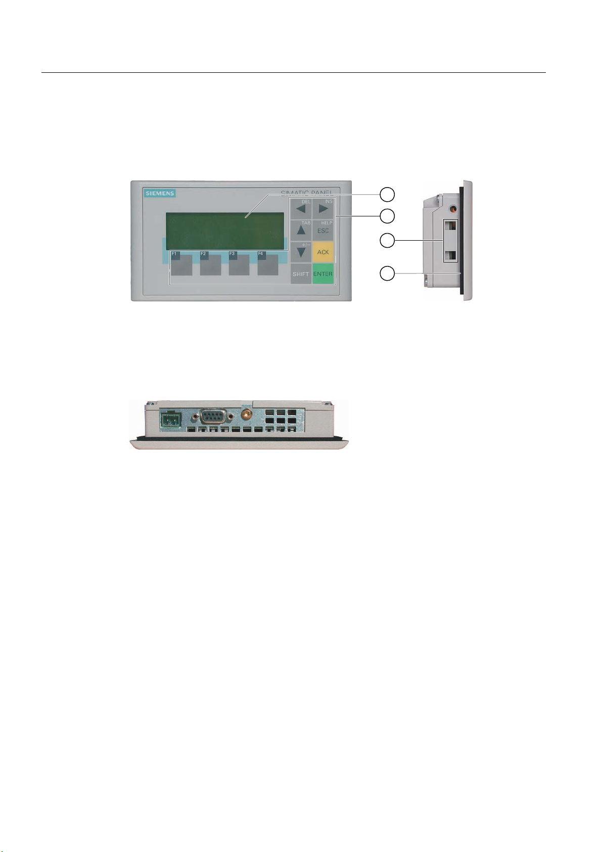
Figure 1-1 Front and side view
① Display
② Membrane keyboard
③ Clamping recess
④ Mounting seal
Figure 1-2 Bottom view
OP 73micro, TP 177micro (WinCC flexible)
12 Operating Instructions, 09/2007, 6AV6691-1DF01-0AB0
Page 13
Overview
1.3 Design of the TP 177micro HMI device
1.3 Design of the TP 177micro HMI device
Views of the HMI device
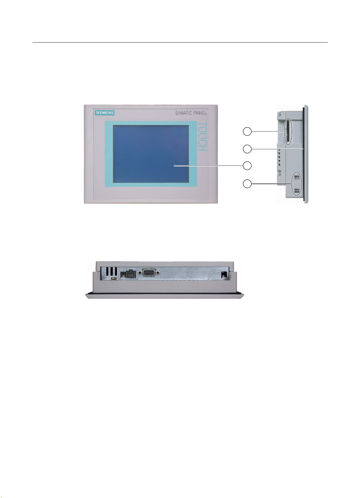
Figure 1-3 Front view and side view
① Construction-related opening – not a slot for a memory card
② Mounting seal
③ Display / Touch screen
④ Clamping recess
Figure 1-4 Bottom view
1.4 Accessories
Accessory kit
The accessory kit contains the following:
● A terminal block for the power supply
● Four mounting clamps for installing a TP 177micro
● Two mounting clamps for installing an OP 73
Additional documents may be enclosed with the accessory kit.
OP 73micro, TP 177micro (WinCC flexible)
Operating Instructions, 09/2007, 6AV6691-1DF01-0AB0
13
Page 14

Overview
1.5 Miscellaneous
1.5 Miscellaneous
PC-PPI adapter
For the conversion from RS 232 to RS 485, order the PC-PPI adapter, Order No.
6ES7 901- 3CB30-0XA0, from Siemens AG. You need the PC-PPI adapter, for example, to
update the operating system or to transfer project data.
Protective membrane
A protective membrane is available for TP 177micro, order no. 6AV6 671-2XC00-0AX0.
1.6 Range of HMI software functions
General
The following tables show the objects the user can integrate in a project for an OP 73micro
and TP 177micro.
Note
The specified values are maximum values of the individual objects. Simultaneous use of
multiple objects with their maximum value can lead to problems in the active project.
Alarms
Table 1-1 Range of functions for alarms
Object Specification OP 73micro TP 177micro
Alarm
Volatile alarm buffer
Number of discrete alarms 250 500
Number of analog alarms 5 20
Length of the alarm text 80 characters 80 characters
Number of tags in an alarm Max. 8 Max. 8
Display Alarm view,
Alarm window
Acknowledge single error alarms Yes Yes
Acknowledge several error alarms simultaneously
(group acknowledgement)
Edit alarm Yes Yes
Alarm indicator Yes Yes
Alarm buffer capacity 100 alarms 128 alarms
Simultaneously queued alarm events Max. 30 Max. 32
View alarm Yes Yes
Delete alarm buffer Yes Yes
Yes Yes
Alarm view,
Alarm window
OP 73micro, TP 177micro (WinCC flexible)
14 Operating Instructions, 09/2007, 6AV6691-1DF01-0AB0
Page 15

Overview
1.6 Range of HMI software functions
Tags, values and lists
Table 1-2 Range of functions for tags, values and lists
Object Specification OP 73micro TP 177micro
Tags Number 500 250
Limit-value monitoring Input Input/Output
Linear Scaling Input/Output Yes Yes
Text lists Number 150 150
Screens
Table 1-3 Range of functions for screens
Object Specification OP 73micro TP 177micro
Screen
Number 250 250
Fields per screen 20 20
Tags per screen 20 20
Complex objects per screen (e.g. bars) 5 5
Template Yes Yes
Infotext
Table 1-4 Range of functions for infotext
Object Specification OP 73micro TP 177micro
Infotext
Length (no. of characters) 320 320
For alarms Yes Yes
For screens Yes Yes
For screen objects (e.g. IO fields) Yes Yes
Help indicator Yes No
OP 73micro, TP 177micro (WinCC flexible)
Operating Instructions, 09/2007, 6AV6691-1DF01-0AB0
15
Page 16

Overview
1.7 Communication with PLCs
Additional functions
Table 1-5 Range of additional functions
Object Specification OP 73micro TP 177micro
Monitor settings Contrast
Touch screen calibration
Screen saver - Yes Yes
Language switching Number of languages 5 5
Graphic object Graphics Graphics / vector
Trend views Number - 25
Trends per view Number 4
Text object Number 2500 500
Password protection Number of passwords 1 1
Yes
No
Yes
Yes
graphic
1.7 Communication with PLCs
Number of connections
Interconnection OP 73micro TP 177micro
Number for MPI/PROFIBUS DP 1 1
Siemens PLCs
The following table shows the Siemens PLCs and protocols or profiles that can be used.
PLC Protocol / profile OP 73micro TP 177micro
S7-200 MPI1 yes yes
1
See also
If you require a baud rate of 9.6 Kbps, use the "DP" profile in WinCC flexible.
The HMI device can communicate only with one S7-200 at a time. The HMI device can be
connected to the S7-200 using a PtP connection or a network.
Communication via a point-to-point connection (Page 57)
Communication in the network (Page 58)
OP 73micro, TP 177micro (WinCC flexible)
16 Operating Instructions, 09/2007, 6AV6691-1DF01-0AB0
Page 17
Safety instructions and general notes
2.1 Safety instructions
Working on the cabinet
WARNING
Open equipment
The HMI device is an open equipment. This means that the HMI device may only be
installed in cubicles or cabinets, whereby the device can be operated from the front panel.
Access to the cubicle or cabinet in which the HMI device is installed should only be possible
by means of a key or tool and for personnel who have received instruction or are
authorized.
Danger, high voltage
Opening the cabinet will expose high voltage parts. Contact with these parts could be fatal.
Switch off the power supply to the cabinet before opening it.
2
Hazardous areas
High frequency radiation
OP 73micro, TP 177micro (WinCC flexible)
Operating Instructions, 09/2007, 6AV6691-1DF01-0AB0
When operating the HMI device in hazardous areas the following warning applies.
WARNING
Explosion Hazard
Do not disconnect while circuit is live unless area is known to be non-hazardous.
Substitution of components may impair suitability for Class I, Division 2 or Zone 2.
NOTICE
Unintentional operating situations
High frequency radiation, from mobile phones for example, can cause unintentional
operating situations.
17
Page 18
Safety instructions and general notes
2.2 Standards, Certificates and Approvals
2.2 Standards, Certificates and Approvals
Valid approvals
CE approval
CAUTION
Valid approvals
The overview below provides information on available approvals
The HMI device itself is certified as shown on the label on its rear panel.
The automation system meets the general and safety-related requirements of the following
EC directives and conforms to the harmonized European standards (EN) for programmable
logic controllers published in the official gazettes of the European Union:
● 89/336/EEC "Electromagnetic Compatibility" (EMC guideline)
● 94/9/EG "Equipment and protective systems intended for use in potentially explosive
atmospheres" (ATEX).
EC declaration of conformity
The EC declarations of conformity are kept available for the responsible authorities at the
following address:
Siemens Aktiengesellschaft
Automation & Drives
A&D AS RD ST PLC
PO Box 1963
D-92209 Amberg
UL certification
Underwriters Laboratories Inc. conforming to
● UL 508 (Industrial Control Equipment)
● CSA C22.2 No. 142, (Process Control Equipment)
or
OP 73micro, TP 177micro (WinCC flexible)
18 Operating Instructions, 09/2007, 6AV6691-1DF01-0AB0
Page 19

Safety instructions and general notes
2.2 Standards, Certificates and Approvals
Underwriters Laboratories Inc. conforming to
● UL 508 (Industrial Control Equipment)
● CSA C22.2 No. 142, (Process Control Equipment)
● UL 1604 (Hazardous Location)
● CSA-213 (Hazardous Location)
Approved for use in
● Class I, Division 2, Group A, B, C, D or
● Class I, Zone 2, Group IIC or
● non-hazardous locations
FM Approval
Ex approval
FM
APPROVED
Factory Mutual Research (FM) conforming to
● Approval Standard Class Number 3611, 3600, 3810
Approved for use in
● Class I, Division 2, Group A, B, C, D T4
● Class I, Zone 2, Group IIC T4
In compliance with EN 50021 (Electrical apparatus for potentially explosive atmospheres;
Type of protection "n")
● II 3 G/D EEx nA II T4
● IP65
● 04 ATEX 1297X
Tick-mark for Australia
N117
The HMI device fulfills the requirements of standard AS/NZS 2064 (Class A).
OP 73micro, TP 177micro (WinCC flexible)
Operating Instructions, 09/2007, 6AV6691-1DF01-0AB0
19
Page 20

Safety instructions and general notes
2.3 Notes about usage
IEC 61131
The HMI device fulfills the requirements and criteria conforming to IEC 61131-2,
Programmable Logic PLCs, Part 2: Operating resource requirements and tests.
2.3 Notes about usage
Use in industry
The HMI device is designed for industrial use. The following standards are met:
● Requirements of the emission of interference EN 61000-6-4: 2001
● Requirements for noise immunity EN 61000-6-2: 2001
Residential use
If the HMI device is used in a residential area, you must take measures to achieve Limit
Class B conforming to EN 55011 for RF interference.
Suitable measures to achieve Limit Class B for suppression of radio interference include:
● Installation of the HMI device in a grounded control cabinet
● Use of filters in electrical supply lines
Use in potentially explosive atmosphere, Zone 2
DANGER
Risk of explosion
Operate the HMI device only in a Zone 2 potentially explosive atmosphere if it has been
identified as approved for such environments.
Figure 2-1 Explosion protection label
● II 3 G/D EEx nA II
● IP65
● 04 ATEX 1297X
WARNING
Personal injury and property damage can occur.
Personal injury and property damage can occur in potentially explosive atmospheres if
an electric plug is disconnected from the HMI device while the system is in operation.
In potentially explosive atmospheres, always turn off power to the HMI device before
disconnecting any connectors.
OP 73micro, TP 177micro (WinCC flexible)
20 Operating Instructions, 09/2007, 6AV6691-1DF01-0AB0
Page 21
Safety instructions and general notes
2.3 Notes about usage
Potentially explosive atmosphere, Zone 2
Potentially explosive atmospheres are organized by zones. The zones are classified
according to the probability of the presence of an explosive atmosphere.
Zone Risk of explosion Example
2 Infrequent and brief development
of an explosive gas atmosphere
Safe zone no
Areas around flanged pipe joints with flat
gaskets in closed rooms
• Outside Zone 2
• Standard applications of distributed IO
WARNING
Observe the degree of protection
The HMI device must be installed in a metal enclosure or in a cabinet The minimum degree
of protection of these is IP54 (conforming to EN 60529). Make allowances for the ambient
conditions under which you install the HMI device. The enclosure must have a
manufacturer's declaration for Zone 2 (conforming to EN 50021).
Special conditions for operation in potentially explosive atmospheres of Zone 2
● In situations where the temperature on the cable or at the cable inlet of this enclosure
exceeds 70° C is or the temperature on the wire branching point exceeds 80° C under
operating conditions, the properties of the cables used must ensure that these can
withstand the actually measured temperatures.
● The cable inlets must be compliant with the required degree of protection (conforming
to 50021.)
● All peripheral devices connected to the HMI device must be certified conforming to
explosion protection types EEx nA or EEx nC.
● Measures must be taken to prevent transient voltages from causing the voltage to exceed
its nominal value by more than 40%.
● Ambient temperature range: 0° C ... 50° C vertical
● The temperature of the HMI device's cabinet surface should not exceed 60° C.
● The HMI device should be switched off immediately and replaced if damaged.
Such damage might be:
– Tears or detachment of individual membranes
– A tear in proximity to the viewing window
OP 73micro, TP 177micro (WinCC flexible)
Operating Instructions, 09/2007, 6AV6691-1DF01-0AB0
21
Page 22

Safety instructions and general notes
2.3 Notes about usage
● A label with the following warning must be attached to the inside of the switch
cabinet/cubing at a place that is clearly visible upon opening:
:DUQLQJ
7KHFRQWUROFDELQHWHQFORVXUHLVRQO\DOORZHG
WREHRSHQIRUDVKRUWWLPHHJJUDSKLFGLDJQRVWLFV
,QWKHPHDQWLPH\RXDUHQRWDOORZHGWRSUHVVDVZLWFKSXOORULQVHUW
PRGXOHVDQGGLVFRQQHFWDQ\HOHFWULFOLQHVFRQQHFWRUV
7KLVZDUQLQJGRHVQRWKDYHWREHWDNHQLQWRFRQVLGHUDWLRQ
LI\RXDUHDZDUHWKDWWKHUHLVQRH[SORVLRQKD]DUG
List of approved HMI devices
The list of approved HMI devices is available on the Internet under:
"
http://www4.ad.siemens.de/view/cs"
under article ID 13702947.
Further information
The "HMI device in potentially explosive atmospheres of Zone 2 and Zone 22" flyer is part of
the package and must be complied with.
Maintenance
Defective HMI devices must be returned to the manufacturer for repair. Repair may only be
carried out by the manufacturer at his site.
Location of the manufacturer:
Siemens AG
Automation & Drives
Werner-von-Siemens-Straße 50
92224 Amberg
Germany
Approval
Note
HMI devices with approval to II 3 G EEx nA II T4 may only be used on SIMATIC systems of
device category 3.
OP 73micro, TP 177micro (WinCC flexible)
22 Operating Instructions, 09/2007, 6AV6691-1DF01-0AB0
Page 23

Safety instructions and general notes
2.4 Electromagnetic compatibility
2.4 Electromagnetic compatibility
Introduction
The HMI device fulfills requirements of the EMC Directive of the domestic European market
and other requirements.
EMC-compliant installation of HMI devices
An EMC-compliant installation of the HMI device and the use of interference-proof cables
form the basis of trouble-free operation. The "Directives for interference-free installation of
PLCs" and the "PROFIBUS Networks" manual also apply for the installation of the HMI
device.
Pulse-shaped interference
The following table shows the EMC properties of the modules with respect to pulse-shaped
interference. A requirement for this is that the HMI device meets the specifications and
directives regarding electrical installation.
Table 2-1 Pulse-shaped interference
Pulse-shaped
interference
Electrostatic discharge
conforming to
IEC 61000-4-2
Burst pulses
(high-speed transient
interference)
conforming to
IEC 61000-4-4
High-power surge pulses conforming to IEC 61000-4-5, external protective circuit required (refer to
S7 300 PLC, Installation, chapter “Lightning and overvoltage protection”).
• Asymmetric coupling
• Asymmetric coupling
Tested with Corresponds to test
intensity
Air discharge: 8 kV
Contact discharge: 4 kV
2 KV power supply cable
2 KV signal cable, > 30 m
1 KV signal cable, < 30 m
2 kV power cable
DC voltage with protective elements
2 KV signal/data cable, > 30 m,
with protective elements as required
1 kV power cable
DC voltage with protective elements
1 KV signal cable, > 30 m,
with protective elements as required
3
3
3
3
OP 73micro, TP 177micro (WinCC flexible)
Operating Instructions, 09/2007, 6AV6691-1DF01-0AB0
23
Page 24

Safety instructions and general notes
2.4 Electromagnetic compatibility
Sinusoidal interference
The table below shows the EMC properties of the modules with respect to sinusoidal
interference. A requirement for this is that the HMI device meets the specifications and
directives regarding electrical installation.
Table 2-2 Sinusoidal interference
Sinusoidal interference Test values Corresponds to
test intensity
RF interference
(electromagnetic fields)
• conforming to
IEC 61000-4-3
• conforming to
IEC 61000-4-3
RF interference current
on cables and cable
shielding conforming to
IEC 61000-4-6
10 V/m with 80 % amplitude modulation of 1 kHz in the
range from 80 MHz to 1 GHz and 1.4 GHz to 2 GHz
10 V/m with 50% pulse modulation at 900 MHz
10 V/m with 50% pulse modulation at 1.89 GHz
Test voltage 10 V with 80% amplitude modulation of
1 kHz in the range from 9 kHz to 80 MHz
3
3
Emission of radio interference
Emission of electromagnetic interference conforming to 55011,
Limit value class A, Group 1, measured at a distance of 10 m:
From 30 to 230 MHz < 40 dB (V/m) quasi-peak
From 230 to 1000 MHz < 47 dB (V/m) quasi-peak
Additional measures
Before you connect an HMI device to the public network, ensure that it is compliant with Limit
Class B conforming to 55022.
OP 73micro, TP 177micro (WinCC flexible)
24 Operating Instructions, 09/2007, 6AV6691-1DF01-0AB0
Page 25

Safety instructions and general notes
2.5 Transport and storage conditions
2.5 Transport and storage conditions
Mechanical and climatic transport and storage conditions
The transport and storage conditions of this HMI device exceed requirements conforming to
IEC 61131-2. The following specifications apply to the transport and storage of an HMI
device in its original packing.
The climatic conditions comply to the following standards:
● IEC 60721-3-3, Class 3K7 for storage
● IEC 60721-3-2, Class 2K4 for transport
The mechanical requirements are compliant with EC 60721-3-2, Class 2M2.
Table 2-3 Transport and storage conditions
Type of condition Permissible range
Drop test (in transport package) ≤ 1 m
Temperature from –20° C to +60° C
Atmospheric pressure from 1080 hPa to 660 hPa,
corresponds to an elevation of - 1000 m to 3500 m
Relative humidity from 10% to 90% without condensation
Sinusoidal vibration conforming to
IEC 60068-2-6
Shock conforming to IEC 60068-2-29 250 m/s2, 6 ms, 1000 shocks
5 Hz to 9 Hz: 3.5 mm
9 Hz to 150 Hz: 9.8 m/s2
NOTICE
Ensure that no condensation (dewing) develops on or inside the HMI device after
transporting it at low temperatures or after it has been exposed to extreme temperature
fluctuations.
The HMI device must have acquired room temperature before it is put into operation. Do
not expose the HMI device to direct radiation from a heater in order to warm it up. If dewing
has developed, wait approximately four hours before you switch on the HMI device.
Prerequisite for the trouble-free and safe operation of the HMI device is proper transport and
storage, installation and assembly and careful operation and maintenance.
Warranty for the HMI device is deemed void if these specifications are ignored.
OP 73micro, TP 177micro (WinCC flexible)
Operating Instructions, 09/2007, 6AV6691-1DF01-0AB0
25
Page 26

Safety instructions and general notes
2.5 Transport and storage conditions
OP 73micro, TP 177micro (WinCC flexible)
26 Operating Instructions, 09/2007, 6AV6691-1DF01-0AB0
Page 27

Planning use
3.1 Mounting information
Mechanical and climatic conditions of use
The HMI device is intended for installation in weatherproof permanent locations. The
conditions of use are compliant with requirements to DIN IEC 60721-3-3:
● Class 3M3 (mechanical requirements)
● Class 3K3 (climatic requirements)
Use with additional measures
Examples of applications where the use of the HMI device requires additional measures:
● In locations with a high degree of ionizing radiation
● In locations with extreme operating conditions resulting from situations as follows:
– Corrosive vapors, gases, oils or chemicals
– Electrical or magnetic fields of high intensity
3
● In plants requiring special monitoring features, for example:
– Elevator systems
– Systems in especially hazardous rooms
Mechanical ambient conditions
The mechanical ambient conditions for the HMI device are specified in the following table in
terms of sinusoidal vibration.
Table 3-1 Mechanical ambient conditions
Frequency range
in Hz
10 ≤ f ≤ 58 Amplitude 0.0375 mm Amplitude 0.075 mm
58 ≤ f ≤ 150 0.5 g constant acceleration Constant acceleration 1 g
OP 73micro, TP 177micro (WinCC flexible)
Operating Instructions, 09/2007, 6AV6691-1DF01-0AB0
Continuous Occasional
27
Page 28

Planning use
3.1 Mounting information
Reduction of vibration
If the HMI device is subjected to greater shocks or vibrations, you must take appropriate
measures to reduce acceleration or amplitudes.
We recommend fitting the HMI device to vibration-absorbent material (on metal shock
absorbers, for example).
Check of mechanical ambient conditions
The following table provides information on the type and scope of the check of mechanical
ambient conditions.
Table 3-2 Check of mechanical ambient conditions
The check
includes
Vibrations Vibration test conforming to
Shock Shock test conforming to
Test standard Remarks
IEC 60068, part 2–6
(sinusoidal)
IEC 60068, part 2–29
Type of vibration:
Transitional rate of the frequency:
1 octave/minute.
10 ≤ f ≤ 58,
Constant amplitude 0.075 mm
58 ≤ f ≤ 150,
Constant acceleration 1 g
Vibration duration:
10 frequency cycles per axis in each of the three
axes vertical to each other
Type of shock: Half-sine
Shock intensity:
Peak value 15 g, duration 11 ms
Direction of impact:
3 shocks in ± direction of axis in each of the
three axes vertical to each other
OP 73micro, TP 177micro (WinCC flexible)
28 Operating Instructions, 09/2007, 6AV6691-1DF01-0AB0
Page 29

Planning use
3.1 Mounting information
Climatic ambient conditions
The HMI device may be used under the following climatic ambient conditions:
Table 3-3 Climatic ambient conditions
Ambient conditions Permissible range Remarks
Temperature
• Vertical mounting
• Inclined mounting
Relative humidity 10% to 90% Without condensation, corresponds to a
Atmospheric pressure 1080 hPa to 795 hPa Corresponds to an elevation of -1000 to
Pollutant concentration SO2: < 0.5 ppm;
from 0° C to 50° C
from 0 °C to 40 °C
relative humidity < 60%, no
condensation
H
S: < 0.1 ppm;
2
relative humidity < 60 %, no
condensation
See the "Mounting positions and type of
fixation" section
relative humidity, stress class 2
conforming to IEC 61131, part 2
2000 m
Test: 10 ppm; 4 days
Test: 1 ppm; 4 days
OP 73micro, TP 177micro (WinCC flexible)
Operating Instructions, 09/2007, 6AV6691-1DF01-0AB0
29
Page 30
Planning use
3.2 Mounting the OP 73micro
3.2 Mounting the OP 73micro
3.2.1 Mounting positions and fixation
Mounting position
The HMI device is designed for mounting in racks, switch cabinets, switchboards and
consoles. In the following, all of these mounting options are referred to by the general term
"cabinet."
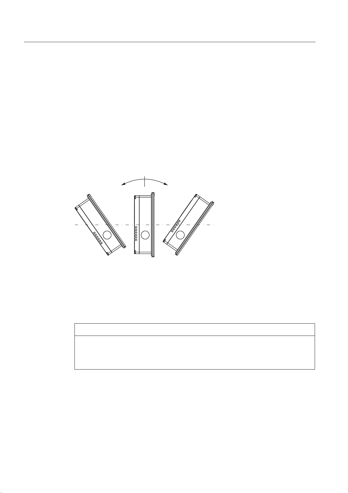
The HMI device is self-ventilated and approved for vertical and inclined mounting in
stationary cabinets.
–+
Figure 3-1 Approved deviations from the vertical mounting position of the OP 73micro without
auxiliary ventilation
Mounting position Deviation from the vertical
① Inclined ≤ –80°
② Vertical 0°
③ Inclined ≤ 80°
CAUTION
Impermissible ambient temperatures
Do not operate the HMI device without auxiliary ventilation if the maximum permissible
ambient temperature is exceeded. The HMI device may otherwise get damaged and its
approvals and warranty will be void!
OP 73micro, TP 177micro (WinCC flexible)
30 Operating Instructions, 09/2007, 6AV6691-1DF01-0AB0
Page 31

Planning use
3.2 Mounting the OP 73micro
Type of fixation
Spring clamps are provided for mounting the device. Hook the clamps into the recesses of
the HMI device. The overall HMI device dimensions are not exceeded by this.
1
2
Figure 3-2 View of a mounting clamp
① Hook
② Recessed head screw
3.2.2 Preparing for mounting
HMI mounting location
What to observe when selecting the mounting location:
● Position the HMI device so that it is not subjected to direct sunlight.
● Position the HMI device to provide an ergonomic position for the operator and select a
suitable mounting height.
● Ensure that the air vents are not covered as a result of the mounting.
● Observe the permissible mounting positions for the HMI device.
Preparing the mounting cut-out
The degrees of protection are only guaranteed when the following is observed:
● Material thickness at the mounting cut-out: 2 mm to 4 mm
● The deviation from plane for the panel cut-out is ≤ 0.5 mm.
This condition must be fulfilled for the mounted HMI device.
● Permissible surface roughness in the area of the seal: ≤ 120 µm (R
The figure below shows the required mounting cut-out:
138
120)
z
+1
+1
68
Figure 3-3 Mounting cut-out for OP 73micro
OP 73micro, TP 177micro (WinCC flexible)
Operating Instructions, 09/2007, 6AV6691-1DF01-0AB0
31
Page 32

Planning use
3.2 Mounting the OP 73micro
Maintaining clearances
The HMI device must be installed with sufficient clearance:
5050
1515
Figure 3-4 Clearance around the OP 73micro
At least 10 mm clearance is required at the rear.
NOTICE
Ensure that the maximum ambient temperature is not exceeded when mounting the device
in a cabinet and especially in a closed enclosure.
OP 73micro, TP 177micro (WinCC flexible)
32 Operating Instructions, 09/2007, 6AV6691-1DF01-0AB0
Page 33

Planning use
3.3 Mounting the TP 177micro
3.3 Mounting the TP 177micro
3.3.1 Mounting positions and fixation
Mounting position
The HMI device is designed for mounting in racks, cabinets, control boards and consoles. In
the following, all of these mounting options are referred to by the general term "cabinet."
The HMI device is self-ventilated and approved for vertical and inclined mounting in
stationary cabinets.
–+
Figure 3-5 Permitted mounting positions
Mounting position Deviation from the vertical
① Inclined ≤ –35°
② Vertical 0°
③ Inclined ≤ 35°
CAUTION
Impermissible ambient temperatures
Do not operate the HMI device without auxiliary ventilation if the maximum permissible
ambient temperature is exceeded. The HMI device may otherwise get damaged and its
approvals and warranty will be void!
OP 73micro, TP 177micro (WinCC flexible)
Operating Instructions, 09/2007, 6AV6691-1DF01-0AB0
33
Page 34

Planning use
3.3 Mounting the TP 177micro
Horizontal mounting
When mounted horizontally, the cable inlets are located at the bottom.
Vertical mounting
When mounted vertically, the cable inlets are on the right.
Type of fixation
Spring clamps are provided for mounting the device. Hook the clamps into the recesses of
the HMI device. The overall HMI device dimensions are not exceeded by this.
1
2
Figure 3-6 View of a mounting clamp
① Hook
② Recessed head screw
OP 73micro, TP 177micro (WinCC flexible)
34 Operating Instructions, 09/2007, 6AV6691-1DF01-0AB0
Page 35

Planning use
3.3 Mounting the TP 177micro
3.3.2 Preparing for mounting
Select the HMI device mounting location
What to observe when selecting the mounting location:
● Position the HMI device so that it is not subjected to direct sunlight.
● Position the HMI device to provide an ergonomic position for the operator and select a
suitable mounting height.
● Ensure that the air vents are not covered as a result of the mounting.
● Observe the permissible mounting positions for the HMI device.
Preparing the mounting cut-out
The degrees of protection are only guaranteed when the following is observed:
● Material thickness at the mounting cut-out: 2 mm to 6 mm
● The deviation from plane for the panel cut-out is ≤ 0.5 mm
This condition must be fulfilled for the mounted HMI device.
● Permissible surface roughness in the area of the seal: ≤ 120 µm (R
The figure below shows the required mounting cut-out:
198
–1
–1
142
Figure 3-7 Mounting cut-out for the HMI device
120)
z
OP 73micro, TP 177micro (WinCC flexible)
Operating Instructions, 09/2007, 6AV6691-1DF01-0AB0
35
Page 36

Planning use
3.3 Mounting the TP 177micro
Maintaining clearances
The following clearance is required around the HMI device in order to its ensure selfventilation:
Figure 3-8 Clearance around the HMI device
At least 10 mm clearance is required at the rear.
NOTICE
Ensure that the maximum ambient temperature is not exceeded when mounting the device
in a cabinet and especially in a closed enclosure.
OP 73micro, TP 177micro (WinCC flexible)
36 Operating Instructions, 09/2007, 6AV6691-1DF01-0AB0
Page 37

Planning use
3.4 Information on insulation tests, protection class and degree of protection
3.4 Information on insulation tests, protection class and degree of
protection
Test voltages
Insulation strength is demonstrated in the type test with the following test voltages
conforming to IEC 61131-2:
Table 3-4 Test voltages
Circuits with a nominal voltage of U
circuits or ground
< 50 V 500 V DC
Class of protection
Protection Class I conforming to IEC 60536, i.e. grounding conductor to profile rail required!
Protection from foreign objects and water
Degree of protection conforming to
IEC 60529
Front panel
Rear panel
The degree of protection provided by the front side can only be guaranteed when the
mounting seal lies completely against the mounting cut-out.
NOTICE
Degree of protection IP65
The degrees of protection are only guaranteed when the following is observed:
• The material strength at the mounting cut-out is at least 2 mm.
• The deviation from the plane of the mounting cut-out in an installed HMI device is
≤ 0.5 mm.
to other
e
Test voltage
Explanation
IP65 in mounted state
IP20
protection against contact with standard test probes
There is no protection against ingress by water.
OP 73micro, TP 177micro (WinCC flexible)
Operating Instructions, 09/2007, 6AV6691-1DF01-0AB0
37
Page 38

Planning use
3.5 Nominal voltages
3.5 Nominal voltages
The following table shows the permitted nominal voltage and the corresponding tolerance
range.
Table 3-5 Permitted nominal voltages
Nominal voltage Tolerance range
+24 V DC 20.4 V to 28.8 V (–15%, +20%)
OP 73micro, TP 177micro (WinCC flexible)
38 Operating Instructions, 09/2007, 6AV6691-1DF01-0AB0
Page 39

Mounting and connection
4.1 Checking the package contents
4.2 Mounting and connecting the OP 73micro
4.2.1 Mounting the HMI device
Check the package contents for visible signs of transport damage and for completeness.
NOTICE
Do not install parts damaged during shipment. In the case of damaged parts, contact your
Siemens representative.
Keep the supplied documentation in a safe place. The documentation belongs to the HMI
device and is required for subsequent commissioning.
4
Requirements
Two mounting clamps from the accessories are required for installation. The mounting seal
must be available on the HMI device. If the mounting seal is damaged, order a replacement
seal.
Mounting
NOTICE
Always mount the HMI device according to the instructions in this manual.
OP 73micro, TP 177micro (WinCC flexible)
Operating Instructions, 09/2007, 6AV6691-1DF01-0AB0
39
Page 40

Mounting and connection
4.2 Mounting and connecting the OP 73micro
Proceed as follows:
1. Check that the mounting seal is fitted on the HMI device.
Do not install the mounting seal turned inside out. This may cause leaks in the mounting
cut-out.
2. Insert the HMI device into the mounting cut-out from the front.
3. Insert the mounting clamps into the recesses on the side of the HMI device.
Adjust and then fasten the clamps.
Figure 4-1 Insert the mounting clamp on the OP 73micro.
4. Tighten the clamps by screwing down the recessed head screw; permitted torque: 0.15
N/m.
NOTICE
Check the fit of the mounting seal on the front. The mounting seal must not protrude
from the HMI device.
Otherwise, repeat steps 1 to 4.
4.2.2 Connecting the HMI device
Requirements
The HMI device must be mounted according to the specifications of these operating
instructions.
Connection sequence
Connect the HMI device in the following sequence:
1. Equipotential bonding
2. Power supply
Perform a power-up test to ensure that the correct polarity of the supply voltage.
3. PLC/configuration computer as necessary
OP 73micro, TP 177micro (WinCC flexible)
40 Operating Instructions, 09/2007, 6AV6691-1DF01-0AB0
Page 41

Mounting and connection
4.2 Mounting and connecting the OP 73micro
NOTICE
Connection sequence
Always follow the correct sequence for connecting the HMI device. Failure to do so may
result in damage to the HMI device.
Connecting the cables
When connecting the cables, ensure that you do not bend any of the contact pins.
Secure the connectors with screws.
Always use shielded data cable. Always use standard cables. For further information, refer to
the SIMATIC HMI Catalog ST 80.
The pin assignment of the interfaces is described in the specifications.
See also
Safety instructions (Page 17)
4.2.2.1 Interfaces
The figure below shows the interfaces of the HMI device.
Figure 4-2 Interfaces of the HMI device
① Power supply connector
② RS 485 interface (IF 1B)
③ Chassis ground terminal
See also
Power supply (Page 146)
RS485 (IF 1B) on OP 73micro (Page 146)
OP 73micro, TP 177micro (WinCC flexible)
Operating Instructions, 09/2007, 6AV6691-1DF01-0AB0
41
Page 42

Mounting and connection
4.2 Mounting and connecting the OP 73micro
4.2.2.2 Connecting the equipotential bonding circuit
Potential differences
Differences in potential between spatially separated system parts can lead to high equalizing
currents over the data cables and therefore to the destruction of their interfaces. This
situation may arise if the cable shielding is terminated at both ends and grounded at different
system parts.
Potential differences may develop when a system is connected to different mains.
General requirements of equipotential bonding
Potential differences must be reduced by means of equipotential bonding in order to ensure
trouble-free operation of the relevant components of the electronic system. The following
must therefore be observed when installing the equipotential bonding circuit:
● The effectiveness of equipotential bonding increases as the impedance of the
equipotential bonding conductor decreases or as its cross-section increases.
● If two system parts are connected to each other via shielded data lines with shielding
connected to the grounding/protective conductor on both sides, the impedance of the
additionally installed equipotential bonding cables may not exceed 10% of the shielding
impedance.
● The cross-section of a selected equipotential bonding conductor must be capable of
handling the maximum equalizing current. The best results for equipotential bonding
2
between two cabinets were achieved with a minimum conductor cross-section of 16 mm
.
● Use equipotential bonding conductors made of copper or galvanized steel. Establish a
large-surface contact between the equipotential bonding conductors and the
grounding/protective conductor and protect these from corrosion.
● Terminate the shielding of the data cable on the HMI device flush and near the
equipotential busbar using suitable cable clamps.
● Route the equipotential bonding conductor and data cables in parallel with minimum
clearance between these. See the wiring diagram.
NOTICE
Equipotential bonding conductor
Cable shielding is not suitable for equipotential bonding. Always use the prescribed
equipotential bonding conductors. The minimum cross-section of a conductor used for
equipotential bonding is 16 mm². When you install MPI and PROFIBUS DP networks,
always use cables with a sufficient crosssection since otherwise the interface modules
may be damaged or destroyed.
OP 73micro, TP 177micro (WinCC flexible)
42 Operating Instructions, 09/2007, 6AV6691-1DF01-0AB0
Page 43

Mounting and connection
4.2 Mounting and connecting the OP 73micro
Wiring diagram
1
2
3 3
See also
4
65
Figure 4-3 Installing the equipotential circuit
① Chassis ground terminal on the HMI device (example)
② Equipotential bonding conductor cross-section: 4 mm
③ Cabinet
④ Equipotential bonding conductor cross-section: min. 16 mm
⑤ Ground terminal
⑥ Cable clamp
⑦ Voltage bus
⑧ Parallel routing of the equipotential bonding conductor and data cable
87
2
2
Electromagnetic compatibility (Page 23)
OP 73micro, TP 177micro (WinCC flexible)
Operating Instructions, 09/2007, 6AV6691-1DF01-0AB0
43
Page 44

Mounting and connection
4.2 Mounting and connecting the OP 73micro
4.2.2.3 Connecting the PLC
Wiring diagram
The following diagram illustrates the connection between the HMI device and PLC.
S7-200
Figure 4-4 Connection to the PLC
The interfaces are described in the Specifications section.
Note when connecting
NOTICE
Always use the approved cables to connect a SIMATIC S7 PLC.
Standard cables are available for the connection. For further information, refer to the
SIMATIC HMI Catalog ST 80.
See also
Communication via a point-to-point connection (Page 57)
Communication in the network (Page 58)
Interfaces (Page 41)
4.2.2.4 Connecting the configuration computer
Wiring diagram
The figure below illustrates the connection between the HMI device and configuration
computer.
Figure 4-5 Connecting the configuration computer
The interfaces are described in the Specifications section.
OP 73micro, TP 177micro (WinCC flexible)
44 Operating Instructions, 09/2007, 6AV6691-1DF01-0AB0
Page 45

Mounting and connection
4.2 Mounting and connecting the OP 73micro
See also
Interfaces (Page 41)
Wiring diagram
The figure below illustrates the connection between the power supply and the HMI device.
Figure 4-6 Connecting the power supply
The interfaces are described in the Specifications section.
Note when connecting
The power terminal block is included in the assembly kit and is designed for conductors with
a maximum cross-section of 1.5 mm
Connecting the terminal block
NOTICE
Damage
Pressure on the screwdriver may damage the HMI device socket if the terminal block is
plugged in when you tighten the screws.
Always remove the terminal block to connect the wires.
Figure 4-7 Connecting the terminal block
*1'
DC +24 V
2
..
Connect the power supply cables to the terminal block as shown in the figure above. Ensure
that the cables are not crossed. Refer to the label showing the pin-out on the rear of the HMI
device.
OP 73micro, TP 177micro (WinCC flexible)
Operating Instructions, 09/2007, 6AV6691-1DF01-0AB0
45
Page 46

Mounting and connection
4.2 Mounting and connecting the OP 73micro
Polarity reversal protection
The HMI device is equipped with a polarity reversal protection circuit.
Connecting the power supply
CAUTION
Ensure safe electrical insulation of the power supply. Always use power supply modules
that conform to IEC 364-4-41 or HD 384.04.41 (VDE 0100, Part 410).
Always use power supply modules that comply to SELV (Safety Extra-Low Voltage) and
PELV (Protective Extra Low Voltage) standards.
The power supply voltage must always be within the specified range to prevent
malfunctions on the HMI device.
Equipotential bonding
Therefore, wire the 24 V output of the power supply to the equipotential circuit.
See also
Interfaces (Page 41)
4.2.3 Switching on power and testing the HMI device
Procedure – Switching on power and testing the HMI device
Proceed as follows:
1. Plug the terminal block into the HMI device.
2. Switch on the power supply.
After power on, the display lights up and the following dialog appears briefly:
OP 73micro
bootloader vx.xx
(2004-xx-xx)
Figure 4-8 Bootloader display
If the HMI device does not start, it is possible the wires on the terminal block have been
crossed. Check the connected wires and change the connections if necessary. The
Loader opens once the operating system has started.
Loader
Transfer
Start
Figure 4-9 Loader view
OP 73micro, TP 177micro (WinCC flexible)
46 Operating Instructions, 09/2007, 6AV6691-1DF01-0AB0
Page 47

Mounting and connection
4.2 Mounting and connecting the OP 73micro
The HMI device automatically sets transfer mode during initial startup if it does no contain
any project data yet. The following dialog appears:
Transfer
Connecting to host.
Figure 4-10 "Transfer" dialog
HELP
ESC
3. Press
to cancel the transfer.
Result
The Loader appears again.
Note
When restarting the system, a project may already be loaded on the HMI device. The system
then skips transfer mode and starts the project.
Use the relevant operator control object to close the project.
Further information on this may be available in your plant documentation.
Navigating in the Loader
Button Action
+/–
or
ENTER
HELP
ESC
Function test
Perform a function test following commissioning. The HMI device is fully functional when one
of the following states is indicated:
TAB
Press one of these cursor keys to select the next entry in arrow
direction.
• The input is confirmed.
• The submenu or dialog shown below opens.
• Move back
Returns to the next higher menu layer.
• Cancel transfer mode
● The "Transfer" dialog is displayed.
● The Loader is displayed.
● A project is started.
Switching off the HMI device
Options for switching off the HMI device:
● Switch off the power supply.
● Disconnect the terminal block from the HMI device.
OP 73micro, TP 177micro (WinCC flexible)
Operating Instructions, 09/2007, 6AV6691-1DF01-0AB0
47
Page 48

Mounting and connection
4.3 Mounting and connecting the TP 177micro
4.3 Mounting and connecting the TP 177micro
4.3.1 Mounting the HMI device
Requirements
Four mounting clamps from the kit are needed to mount the the HMI device. The mounting
seal must be available on the HMI device. If the mounting seal is damaged, order a
replacement seal. The mounting seal is part of the associated service pack.
Mounting
NOTICE
Always mount the HMI device according to the instructions in this manual.
Proceed as follows:
1. Check that the mounting seal is fitted on the HMI device.
Do not install the mounting seal turned inside out. This may cause leaks in the mounting
cut-out.
2. Insert the HMI device into the mounting cut-out from the front.
3. Insert the mounting clamps into the recesses on the side of the HMI device.
Insert and then fasten all four clamps.
Figure 4-11 Installing the mounting clamp on the HMI device
4. Tighten the clamp by screwing down the recessed head screw; permitted torque: 0.15
Nm.
OP 73micro, TP 177micro (WinCC flexible)
48 Operating Instructions, 09/2007, 6AV6691-1DF01-0AB0
Page 49

Mounting and connection
4.3 Mounting and connecting the TP 177micro
NOTICE
Check the fit of the mounting seal on the front. The mounting seal must not protrude
from the HMI device.
Otherwise, repeat steps 1 to 4.
4.3.2 Connecting the HMI device
Requirements
The HMI device must be mounted according to the specifications of these operating
instructions.
Connection sequence
Connect the HMI device in the following sequence:
1. Equipotential bonding
2. Power supply
Perform a power-up test to ensure that the correct polarity of the supply voltage.
3. PLC/configuration computer as necessary
NOTICE
Connection sequence
Always follow the correct sequence for connecting the HMI device. Failure to do so may
result in damage to the HMI device.
Connecting the cables
When connecting the cables, ensure that you do not bend any of the contact pins.
Secure the connectors with screws.
Always use shielded data cable. Always use standard cables. For further information, refer to
the SIMATIC HMI Catalog ST 80.
The pin assignment of the interfaces is described in the specifications.
See also
Safety instructions (Page 17)
OP 73micro, TP 177micro (WinCC flexible)
Operating Instructions, 09/2007, 6AV6691-1DF01-0AB0
49
Page 50

Mounting and connection
4.3 Mounting and connecting the TP 177micro
4.3.2.1 Interfaces
The figure below shows the interfaces of the HMI device.
2 31
Figure 4-12 Interfaces of the HMI device
① Chassis ground terminal
② Power supply connector
③ RS 485 interface (IF 1B)
See also
Power supply (Page 146)
RS 485 (IF 1B) on TP 177micro (Page 147)
4.3.2.2 Connecting the equipotential bonding circuit
Potential differences
Differences in potential between spatially separated system parts can lead to high equalizing
currents over the data cables and therefore to the destruction of their interfaces. This
situation may arise if the cable shielding is terminated at both ends and grounded at different
system parts.
Potential differences may develop when a system is connected to different mains.
OP 73micro, TP 177micro (WinCC flexible)
50 Operating Instructions, 09/2007, 6AV6691-1DF01-0AB0
Page 51

Mounting and connection
4.3 Mounting and connecting the TP 177micro
General requirements of equipotential bonding
Potential differences must be reduced by means of equipotential bonding in order to ensure
trouble-free operation of the relevant components of the electronic system. The following
must therefore be observed when installing the equipotential bonding circuit:
● The effectiveness of equipotential bonding increases as the impedance of the
equipotential bonding conductor decreases or as its cross-section increases.
● If two system parts are connected to each other via shielded data lines with shielding
connected to the grounding/protective conductor on both sides, the impedance of the
additionally installed equipotential bonding cables may not exceed 10% of the shielding
impedance.
● The cross-section of a selected equipotential bonding conductor must be capable of
handling the maximum equalizing current. The best results for equipotential bonding
between two cabinets were achieved with a minimum conductor cross-section of 16 mm
● Use equipotential bonding conductors made of copper or galvanized steel. Establish a
large-surface contact between the equipotential bonding conductors and the
grounding/protective conductor and protect these from corrosion.
● Terminate the shielding of the data cable on the HMI device flush and near the
equipotential busbar using suitable cable clamps.
2
.
● Route the equipotential bonding conductor and data cables in parallel with minimum
clearance between these. See the wiring diagram.
NOTICE
Equipotential bonding conductor
Cable shielding is not suitable for equipotential bonding. Always use the prescribed
equipotential bonding conductors. The minimum cross-section of a conductor used for
equipotential bonding is 16 mm². When you install MPI and PROFIBUS DP networks,
always use cables with a sufficient crosssection since otherwise the interface modules
may be damaged or destroyed.
OP 73micro, TP 177micro (WinCC flexible)
Operating Instructions, 09/2007, 6AV6691-1DF01-0AB0
51
Page 52

Mounting and connection
4.3 Mounting and connecting the TP 177micro
Wiring diagram
1
2
3 3
4
65
Figure 4-13 Installing the equipotential circuit
① Chassis ground terminal on the HMI device (example)
② Equipotential bonding conductor cross-section: 4 mm
③ Cabinet
④ Equipotential bonding conductor cross-section: min. 16 mm
⑤ Ground terminal
⑥ Cable clamp
⑦ Voltage bus
⑧ Parallel routing of the equipotential bonding conductor and data cable
87
2
2
OP 73micro, TP 177micro (WinCC flexible)
52 Operating Instructions, 09/2007, 6AV6691-1DF01-0AB0
Page 53

Mounting and connection
4.3 Mounting and connecting the TP 177micro
4.3.2.3 Connecting the PLC
Wiring diagram
The following diagram illustrates the connection between the HMI device and PLC.
S7-200
Figure 4-14 Connecting the PLC
The interfaces are described in the Specifications section.
Note when connecting
RS 485
NOTICE
Always use the approved cables to connect a SIMATIC S7 PLC.
Standard cables are available for the connection. For further information, refer to the
SIMATIC HMI Catalog ST 80.
See also
Communication via a point-to-point connection (Page 57)
Communication in the network (Page 58)
Interfaces (Page 50)
4.3.2.4 Connecting the configuration computer
Wiring diagram
The figure below illustrates the connection between the HMI device and configuration
computer.
Figure 4-15 Connecting the configuration computer
The interfaces are described in the Specifications section.
OP 73micro, TP 177micro (WinCC flexible)
Operating Instructions, 09/2007, 6AV6691-1DF01-0AB0
53
Page 54

Mounting and connection
4.3 Mounting and connecting the TP 177micro
See also
Interfaces (Page 50)
Wiring diagram
The figure below illustrates the connection between the power supply and the HMI device.
Figure 4-16 Connecting the power supply
Note when connecting
The power terminal block is included in the assembly kit and is designed for conductors with
a maximum cross-section of 1.5 mm
2
.
Connecting the terminal block
NOTICE
Damage
Pressure on the screwdriver may damage the HMI device socket if the terminal block is
plugged in when you tighten the screws.
Always remove the terminal block to connect the wires.
Figure 4-17 Connecting the terminal block
Connect the power supply cables to the terminal block as shown in the figure above. Ensure
that the cables are not crossed. Refer to the label showing the pin-out on the rear of the HMI
device.
*1'
DC +24 V
Polarity reversal protection
The HMI device is equipped with a polarity reversal protection circuit.
OP 73micro, TP 177micro (WinCC flexible)
54 Operating Instructions, 09/2007, 6AV6691-1DF01-0AB0
Page 55

Mounting and connection
4.3 Mounting and connecting the TP 177micro
Connecting the power supply
CAUTION
Ensure safe electrical insulation of the power supply. Always use power supply modules
that conform to IEC 364-4-41 or HD 384.04.41 (VDE 0100, Part 410).
Always use power supply modules that comply to SELV (Safety Extra-Low Voltage) and
PELV (Protective Extra Low Voltage) standards.
The power supply voltage must always be within the specified range to prevent
malfunctions on the HMI device.
Equipotential bonding
Therefore, wire the 24 V output of the power supply to the equipotential circuit.
See also
Interfaces (Page 50)
4.3.3 Switching on power and testing the HMI device
Procedure
Proceed as follows:
1. Plug the terminal block into the HMI device.
2. Switch on the power supply.
The display lights up after power on. A progress bar is shown during startup.
If the HMI device does not start, it is possible the wires on the terminal block have been
crossed. Check the connected wires and change the connections if necessary. The
Loader opens once the operating system has started.
Figure 4-18 Loader view
OP 73micro, TP 177micro (WinCC flexible)
Operating Instructions, 09/2007, 6AV6691-1DF01-0AB0
55
Page 56

Mounting and connection
4.3 Mounting and connecting the TP 177micro
The HMI device automatically switches to "Transfer" mode during initial startup if no
project is already loaded on the device. The following dialog appears:
Figure 4-19 "Transfer" dialog
3. Touch "Cancel" to stop the transfer.
Result
The Loader appears again.
Note
When restarting the system, a project may already be loaded on the HMI device. The system
then skips "Transfer" mode and starts the project.
Use the relevant operator control object to close the project.
Further information on this may be available in your plant documentation.
Function test
Perform a function test following commissioning. The HMI device is fully functional when one
of the following states is indicated:
● The "Transfer" dialog is displayed.
● The Loader is displayed.
● A project is started.
Switching off the HMI device
Options for switching off the HMI device:
● Switch off the power supply.
● Disconnect the terminal block from the HMI device.
OP 73micro, TP 177micro (WinCC flexible)
56 Operating Instructions, 09/2007, 6AV6691-1DF01-0AB0
Page 57

Mounting and connection
4.4 Communication with S7-200
4.4 Communication with S7-200
Introduction
This section is intended for configuration engineers of the HMI device.
The following chapter contains information necessary for configuring:
● Connection options to the PLC
● Communication using WinCC flexible
4.4.1 Topologies
Introduction
The HMI device and PLC can communicate using a PtP connection or within a network.
The HMI device can communicate only with one S7-200 at a time.
4.4.1.1 Communication via a point-to-point connection
In a PtP connection, the HMI device is the only device which is connected directly with the
S7-200. You need an MPI cable or a PROFIBUS bus cable with two PROFIBUS bus
connection plugs to connect the HMI device to the PLC.
Figure 4-20 Point-to-point connection
See also
Connecting the PLC (Page 44)
Connecting the PLC (Page 53)
OP 73micro, TP 177micro (WinCC flexible)
Operating Instructions, 09/2007, 6AV6691-1DF01-0AB0
57
Page 58

Mounting and connection
4.4 Communication with S7-200
4.4.1.2 Communication in the network
Introduction
A network consists of several nodes which are connected to the same bus cable and
communicate with each other. All nodes are assigned a unique network address. Which
devices communicate with each other is defined when the devices are configured.
A network must contain a master station and active nodes and may contain slave stations
and passive nodes. The master actively transmits requests to other devices and can also
respond to requests from other masters. A slave only responds to requests.
You need a PROFIBUS bus cable with PROFIBUS bus connector to install a network.
The HMI device always operates as master station.
The HMI device can communicate only with one S7-200 within the network.
S7-200 as active or passive node
The S7-200 station may be operated on the network in master mode (PPI/master mode) and
in slave mode (PPI/slave mode). The default setting of the S7-200 station is PPI/slave mode.
The OP 73micro and TP 177micro can communicate with a SIMATIC S7-200 in PPI/slave
mode and with a SIMATIC S7-200 in PPI/master mode. The HMI device can be connected
via the CPU interface of the SIMATIC S7-200.
Configuration example:
S7-200 -1
1
2
Figure 4-21 Configuration example for communication in the network
S7-200 -2
3
① The active S7-200-1 (in PPI/master mode) outputs requests to the S7-200-2 station.
② OP 73micro communicates with the S7-200-1 in PPI/master mode.
③ TP 177micro communicates with the S7-200-2 in PPI/slave mode.
④ PG to S7-200-1 or S7-200-2, for example, with control tags
OP 73micro, TP 177micro (WinCC flexible)
58 Operating Instructions, 09/2007, 6AV6691-1DF01-0AB0
Page 59

Mounting and connection
4.4 Communication with S7-200
Several HMI devices on one S7-200
An S7-200 PLC supports the connection of up to three HMI devices per CPU interface. The
DP interface of a CPU215-2DP supports the connection of up to five HMI devices.
Configuration example:
See also
Figure 4-22 Three HMI devices on one S7-200
Connecting the PLC (Page 44)
Connecting the PLC (Page 53)
OP 73micro, TP 177micro (WinCC flexible)
Operating Instructions, 09/2007, 6AV6691-1DF01-0AB0
59
Page 60

Mounting and connection
4.4 Communication with S7-200
4.4.1.3 Configuration instructions
Please observe the following configuration instructions:
Note
For a first-generation SIMATIC S7-200 (CPU 214, 215, 216), use the connection at Port 1 for
communication via MPI/PROFIBUS DP. When using a CPU 214, set a baud rate of
9.6 Kbps.
Note
A cable must be terminated with its characteristic wave impedance. To do this, enable the
terminating resistor on the first and last node of the PROFIBUS/MPI network.
Both nodes must be supplied with power. Of the first and last end nodes of a
PROFIBUS/MPI network, only one can be an HMI device! No other HMI devices should be
connected to the network as terminal nodes.
The RS485 PROFIBUS terminal and the PROFIBUS connector are equipped with a switch
for setting the terminating resistor. Meaning of the ON and OFF switch settings:
OFF: The terminating resistor is disabled, i.e. the bus segment is not terminated.
ON: The terminating resistor is enabled, i.e. the bus segment is terminated.
4.4.2 Configuring communication
Requirements
The following software components are required for communication:
● WinCC flexible configuration software
● STEP 7 MicroWIN configuration software for the SIMATIC S7-200 controller
Driver for the HMI device
The communication driver for S7-200 is supplied with WinCC flexible are installed
automatically.
No special blocks are required in the PLC.
OP 73micro, TP 177micro (WinCC flexible)
60 Operating Instructions, 09/2007, 6AV6691-1DF01-0AB0
Page 61

Mounting and connection
4.4 Communication with S7-200
4.4.2.1 Configuring protocol parameters
Parameters to be set
To set the parameters, double-click "Communication ▶ Connections" in the WinCC flexible
project screen of the HMI device. From the "Communications driver" column of the working
area, select the value "SIMATIC S7-200." Then system automatically writes the default
values of the protocol parameters to the properties dialog. You can now customize the
protocol parameters of your configuration:
Figure 4-23 Creating an S7-200 connection
Device-specific parameters
Set the network parameters for the HMI device under "HMI device." The setting applies to all
communication partners.
● "Interface"
Select the IF1 B interface.
OP 73micro, TP 177micro (WinCC flexible)
Operating Instructions, 09/2007, 6AV6691-1DF01-0AB0
61
Page 62

Mounting and connection
4.4 Communication with S7-200
● "Baudrate"
Set the data baud rate for the network here. The baud rate is determined by the slowest
HMI device connected to the network. Possible baud rates for the HMI devices
OP 73micro and TP 177micro:
– 9.6 Kbps
– 19.2 Kbps
– 187.5 Kbps
The setting must be identical throughout the network.
● "Address"
Set the address of the HMI device here. The address must be unique within the network.
● "Only master on the bus"
na
Network parameters
In the "Network" tab, set the parameters of the network which contains the HMI device.
● "Profile"
Set "MPI" here.
Select "DP" if you need a baud rate of 9.6 Kbps.
● "Highest station address"
Set the highest station address. The highest station address must be equal to or higher
than the highest actual address. The setting must be identical throughout the network.
● "Number of masters"
Set the number of masters operating in the network. HMI devices must be operated in
master mode. The S7-200 may be operated in master mode.
Communication partners
Under "PLC", assign an address to the S7-200 which is to communicate with the HMI device.
● "Address"
Here, set the address of the S7 module (CPU) that is connected to the HMI device.
● "Slot"
This parameter is not necessary.
● "Rack"
This parameter is not necessary.
● "Cyclic operation"
This parameter is not necessary.
Addressing the SIMATIC S7 PLC
The address of your S7-200 PLC is configured using the STEP 7 MicroWIN tool.
OP 73micro, TP 177micro (WinCC flexible)
62 Operating Instructions, 09/2007, 6AV6691-1DF01-0AB0
Page 63

Mounting and connection
4.4 Communication with S7-200
4.4.3 User data areas
4.4.3.1 Communication between HMI device and controller
Communication principle
The HMI device and the S7–200 controller communicate using
● tags and
● user data areas
Tags
The controller and the HMI device exchange data using process values. During
configuration, tags are created pointing to addresses in the PLC. The HMI device reads the
value from the specified address and displays it. The operator can also make an input on the
HMI device that is then written to the address on the controller.
user data areas
In the case of the OP 73micro and TP 177micro, the user data area serves for transmitting
the date and time from the PLC to the HMI device.
User data areas are set up when you create the project in the project window in
WinCC flexible of the HMI device by selecting "Communication ▶ Connections" in the "Area
pointers" work area. Physically, the user data area is in the PLC.
4.4.3.2 Permitted data types
Permitted data types
The table below lists the data types you may use in the configuration of tags and area
pointers.
Table 4-1 Permitted data types
Name Object Data type
Tag V CHAR, BYTE, INT, WORD, DINT, DWORD, REAL, BOOL,
Input I CHAR, BYTE, INT, WORD, DINT, DWORD, REAL, BOOL,
Output Q CHAR, BYTE, INT, WORD, DINT, DWORD, REAL, BOOL,
Flag M CHAR, BYTE, INT, WORD, DINT, DWORD, REAL, BOOL,
Timer T Timer
Counter C INT
STRINGCHAR
STRINGCHAR
STRINGCHAR
STRINGCHAR
OP 73micro, TP 177micro (WinCC flexible)
Operating Instructions, 09/2007, 6AV6691-1DF01-0AB0
63
Page 64

Mounting and connection
4.4 Communication with S7-200
4.4.3.3 Time synchronization via area pointer
Introduction
When the "Date/Time PLC" area pointer is configured, the HMI device reads the date and
time cyclically from the PLC. The position of the "Date/Time PLC" user data area is defined
in the area pointer.
Procedure
To configure the address of the area pointer, select "Communication ▶ Connection", then
select "Area pointer."
Figure 4-24 Creating an area pointer
● Connection
Name of the connection
● Name
Default name of the area pointer set by WinCC flexible.
● Address
Enter the tag address of the area pointer In the PLC here.
● Length
The default length of the area pointer is set by WinCC flexible.
● Acquisition cycle
Here, define an acquisition cycle to enable the HMI device to read an area pointer
cyclically. Make allowances for the fact that a shorter acquisition time may have a
negative influence on HMI device performance.
OP 73micro, TP 177micro (WinCC flexible)
64 Operating Instructions, 09/2007, 6AV6691-1DF01-0AB0
Page 65

Mounting and connection
4.4 Communication with S7-200
● Comment
This is where you can save a comment which describes the use of the area pointer, for
example.
Function
The PLC describes the data area of the "Date/Time PLC" area pointer. All specifications are
coded in BCD format.
The HMI device reads the data cyclically based on the configured acquisition cycle and
synchronizes itself.
Note
Do not configure an extremely short acquisition cycle for the date/time area pointer because
this will have a negative influence on HMI device performance.
Recommendation: Acquisition cycle of 1 minute, if the process allows this.
The HMI device time has a resolution of seconds, regardless of the acquisition cycle.
The date/time data area has the following structure:
DATE_AND_TIME format (in BCD code)
7 . . . . . . 0 7 . . . . . . 0
n+0 Year (80-99/0-29) Month (1-12)
n+1 Day (1-31) Hour (0-23)
n+2 Minute (0-59) Second (0-59)
n+3 Reserved Reserved Weekday
n+4 Reserved Reserved
n+5 Reserved Reserved
Most significant byte Least significant byte Data word
(1-7, 1=Sunday)
Note
Note that when you set a Year value, the system sets the years 1980 through 1999 when 80
to 99 is set and the years 2000 through 2029 when 0 to 29 is set.
OP 73micro, TP 177micro (WinCC flexible)
Operating Instructions, 09/2007, 6AV6691-1DF01-0AB0
65
Page 66

Mounting and connection
4.4 Communication with S7-200
4.4.3.4 Mechanism of error alarm acknowledgment
Introduction
Alarms indicate the process and plant states on the HMI device.
Alarms are configured in WinCC flexible. Each alarm is assigned an alarm bit in the PLC.
Each alarm bit must be a tag or tag element which is configured in WinCC flexible.
Various alarm classes are available. Alarms of the "Error" class must be acknowledged
because of their importance.
The following distinctions are made for acknowledgments:
● Acknowledgment on the HMI device
● Acknowledgment by the PLC
Acknowledgment by the PLC
Acknowledgment of error alarms by the PLC requires the "Write acknowledgment tag"
function to be configured.
When "Write acknowledgment tag" is set in the PLC, the system automatically acknowledges
the corresponding error alarm. This function is identical to the acknowledgment function on
the HMI device, for example, triggered with the "ACK" button.
The "Write acknowledgment tag" bit and the alarm bit must be set in the tag.
Reset the acknowledgment bit before the alarm bit is set again in the error alarm area. The
figure below shows the pulse diagram.
(UURUDODUP
$FNQRZOHGJPHQW
3/&ᇪ+0,GHYLFH
$UULYDORIWKH
HUURUDODUP
$FNQRZOHGJP
YLD3/&
DFNQRZOHGJP
5HVHWRI
ELW
1HZ
HUURUDODUP
OP 73micro, TP 177micro (WinCC flexible)
66 Operating Instructions, 09/2007, 6AV6691-1DF01-0AB0
Page 67

Mounting and connection
4.4 Communication with S7-200
Acknowledgment on the HMI device
The PLC can only detect an error alarm acknowledgment at the HMI device if the "Read
acknowledgment tag" bit is configured. The HMI device sets the "Read acknowledgment tag"
bit in the PLC after it has acknowledged an alarm.
In order to generate a signal transition each time the acknowledgment bit is set, the HMI
device initially resets the corresponding "Read acknowledgment tag" bit when an error alarm
bit is set. There is a certain time-based offset between these two operations due to the
processing time of the HMI device.
The figure below shows the pulse diagram.
(UURUDODUP
$FNQRZOHGJPHQW
+0,GHYLFHᇪ3/&
See also
$UULYDORIWKH
HUURUDODUP
5HVHWRI
DFNQRZOHGJPELW
Overview (Page 127)
Acknowledging an Alarm (Page 134)
Acknowledging an Alarm (Page 131)
$FNQRZOHGJP
YLD+0,GHYLFH
1HZ
HUURUDODUP
OP 73micro, TP 177micro (WinCC flexible)
Operating Instructions, 09/2007, 6AV6691-1DF01-0AB0
67
Page 68

Mounting and connection
4.4 Communication with S7-200
OP 73micro, TP 177micro (WinCC flexible)
68 Operating Instructions, 09/2007, 6AV6691-1DF01-0AB0
Page 69

Operator control components and LEDs
5.1 Front side operator control components and indicators on the OP
73micro
2
1
Figure 5-1 Operator control components and LEDs
① Soft keys
② System keys – control keys
Standard input device at the HMI device is the keyboard. This is basically composed of two
key groups:
5
● Soft keys
F1 to F4
The soft keys can only be assigned within a project and do not have any function in the
Loader menu.
● System keys
OP 73micro, TP 177micro (WinCC flexible)
Operating Instructions, 09/2007, 6AV6691-1DF01-0AB0
These include the control keys, for example.
NOTICE
Unintentional actions
Unwanted actions may be triggered if the operator unintentionally actuates several keys
at once.
Never press more than two keys simultaneously.
Keyboard damage
Operation of the keys with hard, pointed or sharp objects or hard impact may lead to a
considerable reduction of the service life and even to complete failure.
Always use your fingers to operate the keys of your HMI device.
69
Page 70

Operator control components and LEDs
5.2 Front side operator control components and LEDs on the TP 177micro
See also
Design of the OP 73micro HMI device (Page 12)
5.2 Front side operator control components and LEDs on the TP 177micro
1
Figure 5-2 Operator control components
See also
① Display with touch screen
Standard input unit at the HMI device is the touch screen. All operator control objects
required for operator input are displayed on the touch screen once the HMI device has
started.
NOTICE
Unintentional actions
Never touch more than one point on the display. Never touch more than one touch object at
a time, otherwise you may trigger unintentional actions.
Damaging the touch screen
The use of with hard, sharp or pointed items or applying excessive pressure when
operating the touch screen will substantially reduce its useful life and even lead to total
failure.
Always operate the HMI device touch screen with your fingers or with a touch pen.
Design of the TP 177micro HMI device (Page 13)
OP 73micro, TP 177micro (WinCC flexible)
70 Operating Instructions, 09/2007, 6AV6691-1DF01-0AB0
Page 71

Configuring the operating system
6.1 Configuring the operating system for the OP 73micro
6.1.1 Overview
Loader
The figure below shows the Loader. It appears briefly when the HMI device starts up.
Loader
Transfer
Start
Info/Settings
Figure 6-1 Loader
The Loader menu commands have the following functions:
● "Transfer"
6
Select this menu command to set the HMI device transfer mode.
● "Start"
Select this menu command to start the project which is stored on the HMI device.
● "Info/Settings"
Select this menu command to open the HMI device configuration menu.
The Loader also appears when you close the project.
Navigating in the Loader
Button Action
+/–
ENTER
HELP
ESC
OP 73micro, TP 177micro (WinCC flexible)
Operating Instructions, 09/2007, 6AV6691-1DF01-0AB0
or
TAB
By pressing one of these buttons, you select the next menu command
in the direction of the cursor key.
The corresponding menu opens.
Returns to the next higher menu layer.
71
Page 72

Configuring the operating system
6.1 Configuring the operating system for the OP 73micro
Editing dialog entries
Button Action
ENTER
HELP
ESC
+/–
or
TAB
Selects the previous or next list entry.
The selected list entry is accepted.
You can undo your input as long you have not yet confirmed the
ENTER
selected list entry with
.
See also
Switching on power and testing the HMI device (Page 46)
6.1.2 "Info/Settings" menu
6.1.2.1 Overview
Requirements
"Info/Settings" was called in the Loader.
"Info/Settings" menu
Info/Settings
Contrast
Device Info
Version Info
Logon/Settings
Figure 6-2 "Info/Settings" menu
"Contrast" Menu command for setting the display contrast
"Device Info" Menu command with information on the HMI device
"Version Info" Menu command with information on the version of the HMI device image
"Logon/Settings" Menu command of the "Logon/Settings" menu
OP 73micro, TP 177micro (WinCC flexible)
72 Operating Instructions, 09/2007, 6AV6691-1DF01-0AB0
Page 73

Configuring the operating system
6.1 Configuring the operating system for the OP 73micro
Password protection
You can protect the "Logon/Settings" menu from unauthorized access by assigning a
password.
This prevents inadvertent wrong operation and increases security for the plant or machine
security because access to the settings is denied. If the user does not enter a password, this
user can only access the "Contrast", "Device Info" and "Version Info" menu commands.
When a password is assigned, the following dialog appears when the user attempts to open
the "Logon/Settings" menu:
Password
|
Figure 6-3 Password dialog
You need to enter the password again to access the "Logon/Settings" menu after you closed
the previous session.
See also
NOTICE
Password no longer available
If the Loader password is no longer available, you can only call the "Logon/Settings" menu
again after you update the operating system.
All data on the HMI device will be overwritten when you update the operating system.
Note
The currently active entry is always indicated in a dialog.
Assigning, editing and deleting passwords (Page 77)
Updating the operating system using WinCC flexible (Page 101)
Updating the operating system in ProSave (Page 102)
OP 73micro, TP 177micro (WinCC flexible)
Operating Instructions, 09/2007, 6AV6691-1DF01-0AB0
73
Page 74

Configuring the operating system
6.1 Configuring the operating system for the OP 73micro
6.1.2.2 Setting screen contrast
Requirements
"Info/Settings ▶ Contrast" was selected from the Loader menu.
Principle
Contrast
Press Up/Down to
change contrast.
Figure 6-4 "Contrast" dialog
NOTICE
Screen contrast
The screen contrast can be increased and reduced within a wide range. Note that this may
lead to the screen content becoming unrecognizable under unfavorable lighting conditions.
This dialog is used to adjust the contrast and therefore indirectly controls screen brightness.
+/–
reduces the contrast and
TAB
increases the contrast.
6.1.2.3 Displaying information about the HMI device
Requirements
"Info/Settings ▶ Device Info" was selected from the Loader menu.
Principle
Figure 6-5 "Device Info" dialog
This dialog is used to indicate the name of the HMI device ("Device") and the size of internal
Flash memory ("Flashsize"). The Flash memory is used to store the HMI device image and
project data. The size of the internal Flash memory does not correspond to the available
working memory for a project. This dialog is read only.
OP 73micro, TP 177micro (WinCC flexible)
74 Operating Instructions, 09/2007, 6AV6691-1DF01-0AB0
Page 75

Configuring the operating system
6.1 Configuring the operating system for the OP 73micro
6.1.2.4 Viewing information about the version of the HMI device image
Requirements
"Info/Settings ▶ Version Info" was selected from the Loader menu.
Principle
Version Info
01.00.00.00_05.08
BL 0.17/2004-xx-xx
Figure 6-6 "Version Info" dialog – Example
The "Version Info" dialog shows information on the Bootloader and the HMI device image file
and therefore the version of the operating system.
This information is required when you contact A&D Technical Support.
6.1.3 "Settings" menu
6.1.3.1 Overview
Requirement
"Info/Settings ▶ Logon/Settings" was selected from the Loader menu. You have entered the
password for the "Settings" menu.
"Settings" menu
Settings
Startup Delay
Screensaver
---------------
Figure 6-7 "Settings" menu
"Startup Delay" Menu command for setting the startup delay on the HMI device
"Screen Saver" Menu command for the screen saver
"Password" Menu command for the password
"Transfer Settings" Menu command for transfer settings
Select the "Settings" menu to edit the system settings for your HMI device.
Access to this menu can be protected by a password.
OP 73micro, TP 177micro (WinCC flexible)
Operating Instructions, 09/2007, 6AV6691-1DF01-0AB0
75
Page 76

Configuring the operating system
6.1 Configuring the operating system for the OP 73micro
Procedure
Proceed as follows:
1. Close the project.
2. Open the "Logon/Settings" menu.
3. Edit the settings.
4. Close the "Logon/Settings" menu.
6.1.3.2 Setting the delay
Requirements
"Info/Settings ▶ Logon/Settings ▶ Startup Delay" was selected from the Loader menu.
Principle
Startup Delay
Value: Sec.3
Figure 6-8 "Startup Delay" dialog
The delay defines the period which the HMI device automatically delays the startup of a
stored project.
When the value "0" is set, the project starts immediately. It is then no longer possible to call
the Loader after switching on the HMI device. To handle this situation, you must have
configured an operator control object you can use to close the project.
Valid range of values: 0 s to 60 s.
6.1.3.3 Setting the screen saver
Requirement
"Info/Settings ▶ Logon/Settings ▶ Screen saver" was selected from the Loader menu.
Principle
Screensaver
Value: Min.
Figure 6-9 "Screen saver" dialog
Use this dialog to set the activation delay for the screen saver.
0
Valid range of values: 5 min to 360 min. The screen saver is disabled when you set 0.
OP 73micro, TP 177micro (WinCC flexible)
76 Operating Instructions, 09/2007, 6AV6691-1DF01-0AB0
Page 77

Configuring the operating system
6.1 Configuring the operating system for the OP 73micro
6.1.3.4 Assigning, editing and deleting passwords
Introduction
To restrict access to the "Settings" menu to specific members of staff, define a password in
the "Password" dialog.
Requirements
● "Info/Settings ▶ Logon/Settings ▶ Password" was selected from the Loader menu.
● The "Password" dialog opens.
Password
|
Figure 6-10 "Password" dialog
Procedure – Assigning and editing passwords
Proceed as follows:
1. Enter the password.
TAB
Select the first character with
Note
or
+/–
. Press
INS
to enter additional characters.
Password entry
The last character of the password entered is shown in plain text. The remaining
characters are represented by a ∗ character.
2. Press
ENTER
You have now completed entry of the password. The "Confirm Password" dialog appears.
Confirm Password
|
Figure 6-11 "Confirm Password" dialog
You need to enter the password twice to confirm it.
1. Enter the password again.
ENTER
2. Press
,
You have now completed the password confirmation. The password is accepted if both
password entries are identical. Otherwise, an error message appears. The "Settings"
menu opens. Repeat the password input.
OP 73micro, TP 177micro (WinCC flexible)
Operating Instructions, 09/2007, 6AV6691-1DF01-0AB0
77
Page 78

Configuring the operating system
6.1 Configuring the operating system for the OP 73micro
Result
● The "Settings" menu opens.
● The "Settings" menu is password protected.
Procedure – Deleting a password
Proceed as follows:
Result
See also
1. Press
ENTER
– do not enter any other characters.
The "Confirmation" dialog opens.
2. Press
ENTER
– do not enter any other characters.
The system confirms the deletion.
● The "Settings" menu opens.
● You have revoked the password protection of the "Settings" menu.
Overview (Page 72)
OP 73micro, TP 177micro (WinCC flexible)
78 Operating Instructions, 09/2007, 6AV6691-1DF01-0AB0
Page 79

Configuring the operating system
6.1 Configuring the operating system for the OP 73micro
6.1.3.5 Configure the data channel
Introduction
By disabling a data channel, you can protect the HMI device from unintentional overwriting of
project data and of the HMI device image.
Requirements
"Info/Settings ▶ Logon/Settings ▶ Transfer Settings" was selected from the Loader menu.
Transfer Settings
Channel1: Serial
Figure 6-12 "Transfer Settings" menu
Procedure
1. Press
ENTER
.
The "Channel1: Serial" dialog opens.
Channel 1: serial
Value: Enable
Figure 6-13 "Channel1: Serial" dialog
This dialog is used to configure the RS495 port for serial data transfer.
1. Select the relevant setting using the
TAB
and
+/–
cursor keys.
– "Disable"
Serial data transfer is disabled.
– "Enable"
Serial data transfer is enabled.
ENTER
2. Accept the required value with
Note
.
Transfer settings
The data channel must be enabled to allow the download of project data from the
configuration computer to the HMI device.
OP 73micro, TP 177micro (WinCC flexible)
Operating Instructions, 09/2007, 6AV6691-1DF01-0AB0
79
Page 80

Configuring the operating system
6.2 Configuring the operating system for the TP 177micro
6.2 Configuring the operating system for the TP 177micro
6.2.1 Overview
Loader
The figure below shows the Loader. It appears briefly when the HMI device starts up.
Figure 6-14 HMI device Loader
The Loader buttons have the following functions:
● Use the "Transfer" button to set "Transfer" mode on the HMI device.
● Press the "Start" button to open the project stored on the HMI device.
● Press "Control Panel" to open the HMI device Control Panel.
The Control Panel is used to configure various settings such as the transfer settings.
The Loader also appears when you close the project.
Password protecting the Control Panel
You can protect the Control Panel from unauthorized access. You can read the settings in
the Control Panel without entering a password but you cannot edit all settings.
This prevents inadvertent wrong operation and increases security for the plant or machine
security because access to the settings is denied.
NOTICE
If the Control Panel password is no longer available, you cannot change settings in the
Control Panel unless you update the operating system.
All data on the HMI device will be overwritten when you update the operating system.
OP 73micro, TP 177micro (WinCC flexible)
80 Operating Instructions, 09/2007, 6AV6691-1DF01-0AB0
Page 81

Configuring the operating system
6.2 Configuring the operating system for the TP 177micro
See also
Switching on power and testing the HMI device (Page 55)
6.2.2 Control Panel
6.2.2.1 Overview
Control Panel of the HMI device
The HMI device Control Panel can be used to modify the following HMI device settings:
● Screen settings
● Transfer settings
Opening the Control Panel
Open the Control Panel using the HMI device Loader.
The following options are available to open the Loader:
● The Loader appears briefly after starting the HMI device.
● During runtime:
If configured, touch the relevant operator control object to stop the project. The Loader is
displayed. Further information on this may be available in your plant documentation.
Touch the "Control Panel" button in the Loader to open the HMI device Control Panel.
Figure 6-15 HMI device Control Panel
"OP" Change screen settings, display information on HMI device, calibrate touch
screen
"Password" Set password protection for the Control Panel
"Screen Saver" Configuring the screen saver
"Transfer" Configure the data channel
OP 73micro, TP 177micro (WinCC flexible)
Operating Instructions, 09/2007, 6AV6691-1DF01-0AB0
81
Page 82

Configuring the operating system
6.2 Configuring the operating system for the TP 177micro
General Procedure
Proceed as follows to change settings in the Control Panel:
1. You must exit the project before changing settings in the Control Panel. Use the relevant
operator control object provided in the project.
2. Open the Control Panel as described above.
3. To change settings, touch the respective input field or check box and use the displayed
screen keyboard if necessary. Enter the required password if the Control Panel is
protected against unauthorized access. Change the HMI device settings in the Control
Panel.
Close the Control Panel: Touch the
4. Start the project using the Loader.
6.2.2.2 Changing screen settings
Requirements
The "OP" icon on the Control Panel has been touched.
Procedure
Proceed as follows:
1. From the "OP Properties" dialog, select the "Display" tab.
button.
1
2
3
4
Figure 6-16 "OP Properties" dialog, "Display" tab
① Button for increasing the contrast
② Button for reducing contrast
③ Screen orientation settings
④ Input field for the delay time at the startup of the HMI device
OP 73micro, TP 177micro (WinCC flexible)
82 Operating Instructions, 09/2007, 6AV6691-1DF01-0AB0
Page 83

Configuring the operating system
6.2 Configuring the operating system for the TP 177micro
2. The "Contrast" group contains the "UP" and "DOWN" buttons. To adjust the screen
contrast:
– Touch the "UP" button to increase screen contrast.
– Touch the "DOWN" button to reduce screen contrast.
3. The "Orientation" group contains the "Landscape" and "Portrait" buttons. To adjust the
screen orientation:
– Set the "Landscape" check box to set the HMI device screen for horizontal orientation.
– Set the "Portrait" check box to set the HMI device screen for vertical orientation.
4. The "Startup Delay" group contains the "Delay time" input field you can use to adjust the
delay at the startup of your HMI device. The delay represents the interval in seconds
which expires between the appearance of the Loader and start of the project.
When the value "0" is set, the project starts immediately. It is then no longer possible to
call the Loader after switching on the HMI device. To handle this situation, you need to
configure an operator control object with "Close project" function.
The valid value range is 0 s to 60 s.
Result
Screen orientation
5. Close the dialog and save your entries with
. Touch to discard the values.
You have completed your HMI device screen settings.
The orientation of the screen is determined by the configuration engineer when he creates
the project. When the project is transferred to the HMI device, the appropriate screen
orientation is set automatically.
NOTICE
If there is a project on the HMI device, do not change the screen orientation.
You can change the screen orientation in the Control Panel, for example, if you have to
operate the Loader on a vertically installed HMI device without the project.
OP 73micro, TP 177micro (WinCC flexible)
Operating Instructions, 09/2007, 6AV6691-1DF01-0AB0
83
Page 84

Configuring the operating system
6.2 Configuring the operating system for the TP 177micro
6.2.2.3 Displaying information about the HMI device
Requirements
You have touched the "OP" icon on the Control Panel.
Procedure
Proceed as follows:
1. Open the "OP Properties" dialog and select the "Device" tab.
1
2
3
4
5
Figure 6-17 "OP Properties" dialog, "Device" tab – example
① HMI device name
② Version of the HMI device image
③ Version of the boot loader
④ Boot loader release date
⑤ The Flash memory is used to store the HMI device image and project data.
2. The "Device" tab is used to display specific HMI device information. There are no input
options.
This information is required when you contact A&D Technical Support.
3. Use
Note
or to close the dialog when the information is no longer required.
The size of the internal Flash memory does not correspond to the available working
memory for a project.
OP 73micro, TP 177micro (WinCC flexible)
84 Operating Instructions, 09/2007, 6AV6691-1DF01-0AB0
Page 85

Configuring the operating system
6.2 Configuring the operating system for the TP 177micro
6.2.2.4 Calibrating the touch screen
Introduction
Depending on the mounting position and viewing angle, it is possible that parallax may occur
when operating the HMI device. In order to prevent any operating errors as a result, calibrate
the screen again in the startup phase or during runtime.
Requirements
The "OP" icon on the Control Panel has been touched.
Procedure
Proceed as follows:
1. Open the "OP Properties" dialog, then select the "Touch" tab.
Result
1
2
Figure 6-18 "OP Properties" dialog, "Touch" tab
① If the HMI device does not react precisely to a touch, the touch screen may require
calibration.
② Button for calibrating the touch screen
2. Touch the "Recalibrate" button.
3. Follow the instructions on the HMI device screen.
4. Close the dialog with
.
The HMI device touch screen is now recalibrated.
OP 73micro, TP 177micro (WinCC flexible)
Operating Instructions, 09/2007, 6AV6691-1DF01-0AB0
85
Page 86

Configuring the operating system
6.2 Configuring the operating system for the TP 177micro
6.2.2.5 Changing the password setting for the Control Panel
Requirements
The "Password" icon in the Control Panel has been touched.
The "Password Properties" dialog is shown.
1
2
Figure 6-19 "Password Properties" dialog
① Password input field
② Input field for entering the password a second time
Procedure – Entering a password
Proceed as follows:
1. Enter a password in the "Password" input field.
Touch the input field. The alphanumerical screen keyboard is displayed.
2. Repeat the password entry in the "Confirm Password" input field.
3. Close the dialog with
NOTICE
The password may not contain space characters or the special characters * ? . % / \ ' ".
Result
The Control Panel is protected from unauthorized access. Without entering a password, you
can read some settings but you cannot change them.
.
NOTICE
If the Control Panel password is no longer available, you cannot change settings in the
Control Panel unless you update the operating system.
All data on the HMI device will be overwritten when you update the operating system.
OP 73micro, TP 177micro (WinCC flexible)
86 Operating Instructions, 09/2007, 6AV6691-1DF01-0AB0
Page 87

Configuring the operating system
6.2 Configuring the operating system for the TP 177micro
Procedure – Deleting a password
Proceed as follows:
1. Delete the entries for "Password" and "Confirm Password".
2. Close the dialog with
Result
Password protection for the Control Panel menu is revoked.
See also
Overview (Page 80)
6.2.2.6 Setting the Screen Saver
Introduction
You can set a period of time for automatic activation of the screen saver on the HMI device.
The screen saver is automatically activated if the HMI device is not operated within the
specified period of time.
The screen saver stops in the following situations:
● When you touch the touch screen.
● A message is displayed.
.
Requirements
Procedure
The "Screen Saver" dialog has been opened with the "Screen Saver" icon.
Figure 6-20 "Screen saver" dialog
Proceed as follows:
1. Enter the number of minutes before the screen saver is to be activated.
Touch the input field. You can enter a value between 5 and 360 minutes. Entering "0"
deactivates the screen saver.
2. Close the dialog and save your entries with
. Touch to discard the entries.
OP 73micro, TP 177micro (WinCC flexible)
Operating Instructions, 09/2007, 6AV6691-1DF01-0AB0
87
Page 88

Configuring the operating system
6.2 Configuring the operating system for the TP 177micro
NOTICE
Activating the Screen Saver
You should always activate the screen saver. Otherwise, the screen contents may leave
a burn-in effect in the background if they appear too long.
This effect is reversible, however.
Result
The screen saver for the HMI device has now been set.
6.2.2.7 Configure the data channel
Introduction
By disabling a data channel, you can protect the HMI device from unintentional overwriting of
project data and of the HMI device image.
Requirements
Procedure
You have touched the "Transfer" icon on the Control Panel.
The "Transfer Settings" dialog is displayed.
1
Figure 6-21 "Transfer Settings" dialog
This dialog is used to configure the RS495 port for serial data transfer.
① Group for data channel 1 (Channel 1)
Enable the "Channel 1" data channel by setting the "Enable Channel" check box:
● Set the "Enable Channel" check box to enable serial transfer.
● Reset the "Enable Channel" check box to disable serial transfer.
Note
Transfer settings
The data channel must be enabled to allow the download of project data from the
configuration computer to the HMI device.
OP 73micro, TP 177micro (WinCC flexible)
88 Operating Instructions, 09/2007, 6AV6691-1DF01-0AB0
Page 89

Preparing and backing up a project
7.1 Overview
Configuration and process management phases
HMI devices can be used to operate and monitor tasks in process and production
automation. The plant screens on the HMI devices are used to provide a clearer overview of
active processes. The HMI device project, which includes the plant screens, is created
during the configuration phase.
Once the project is transferred to the HMI device and the HMI device is connected to a PLC
in the automation system, processes can be operated and monitored in the process
management phase.
&RQILJXUDWLRQSKDVH
&RQILJXUDWLRQ3&
7
&UHDWHSURMHFW
7HVWWKHSURMHFW
6LPXODWHWKHSURMHFW
+0,GHYLFHGHSHQGHQW
6DYHWKHSURMHFW
3URFHVVFRQWUROSKDVH
Figure 7-1 Configuration and process management phases
OP 73micro, TP 177micro (WinCC flexible)
Operating Instructions, 09/2007, 6AV6691-1DF01-0AB0
7UDQVIHUWKHSURMHFW
+0,GHYLFH 2SHUDWHWKHSURMHFW
&RQQHFWLRQWRWKH3/&
3/&
89
Page 90

Preparing and backing up a project
7.1 Overview
Transferring the project to the HMI device
The following can be performed to transfer a project to an HMI device:
● Transfer the project from the configuration computer
● Restore the project from a PC using ProSave
In this case, an archived project is transferred from a PC to the HMI device. The
engineering software need not be installed on this PC.
These procedures can be are available for commissioning and recommissioning a project.
Commissioning and recommissioning
● When the HMI device is commissioned there is no project at first.
The HMI device is also in this state after the operating system has been updated.
● When recommissioning, any project on the HMI device is replaced.
7.1.1 Setting the operating mode
Operating modes
Operating modes of the HMI device:
● Offline
● Online
● Transfer
"Offline mode" and "Online mode" can be set on the configuration computer and on the HMI
device. To set these modes on the HMI device, use a corresponding operator control object
of the project.
Changing the operating mode
The configuration engineer must have configured an appropriate operator control object to
allow a change of the operating mode on the HMI device during ongoing operation.
Further information on this may be available in your plant documentation.
"Offline" mode
In this mode, there is no communication between the HMI device and PLC. Although the
HMI device can be operated, it cannot exchange data with the PLC.
"Online" mode
In this mode, the HMI device and PLC communicate. You can operate the plant on the HMI
device according to your system configuration.
OP 73micro, TP 177micro (WinCC flexible)
90 Operating Instructions, 09/2007, 6AV6691-1DF01-0AB0
Page 91

Preparing and backing up a project
7.1 Overview
"Transfer" mode
In this mode, you can transfer a project from the configuration computer to the HMI device or
backup and restore HMI device data, for example.
The following options are available for setting "Transfer" mode on the HMI device:
● When the HMI device starts up
Start "Transfer" mode manually in the HMI device Loader.
● During ongoing operation
Start transfer mode manually within the project using an operator control object.
7.1.2 Reusing existing projects
You can reuse existing projects on the HMI devices.
The following cases are possible:
1. Reusing projects on OP 73micro
Existing OP3 projects can be reused on OP 73micro.
Migrate the OP3 project to WinCC flexible (compact, standard, advanced) into an OP 73
project, then replace your HMI device with the OP 73micro.
2. Reusing existing projects on TP 177micro
– TP 170A project available in ProTool
Migrate the TP 170A project to WinCC flexible (compact, standard, advanced) and
then replace your HMI devices with a TP 177micro.
– TP 170A project available in WinCC
In WinCC flexible (Compact, Standard, Advanced), replace your HMI device with a
TP 177micro.
– TP 170micro project available in WinCC flexible
In WinCC flexible (Compact, Standard, Advanced), replace your HMI device with a
TP 177micro.
Note
Projects for TP 070 can not be reused.
For more information, please see the online help for WinCC flexible or the "WinCC flexible
Migration" user manual.
OP 73micro, TP 177micro (WinCC flexible)
Operating Instructions, 09/2007, 6AV6691-1DF01-0AB0
91
Page 92

Preparing and backing up a project
7.2 Transfer
7.1.3 Data Transfer Options
Overview
The following table shows the options for transferring data between the configuration
computer and OP 73micro or TP 177micro.
Type Type OP 73micro TP 177micro
Serial (with reset to factory setting) No No Backup
Serial Yes Yes
1)
system
1)
Applies to complete restore
2)
Applies to restoring the password list
Serial (with reset to factory setting) Yes
Serial No
Serial (with reset to factory setting) Yes Yes Updating the operating
Serial No No
Serial (with reset to factory setting) No No Transfer of a project
Serial Yes Yes
1)
/ No
/ Yes
2)
Yes
2)
No
1)
1)
/ Yes
/ No
2)
Restore
2)
Serial transmission
You can use one of the following adapters for the serial transmission to the configuration PC:
● RS 232/PPI cable MM Multimaster
● USB/PPI cable MM Multimaster (as of manufacturer version 05 of the cable)
7.2 Transfer
7.2.1 Overview
Transfer
During transfer, the project is downloaded from the configuration computer to the HMI
device.
"Transfer" mode can be started on the HMI device.
Transferred data is written directly to the flash memory on the HMI device. The data channel
must be configured before you start the transfer.
OP 73micro, TP 177micro (WinCC flexible)
92 Operating Instructions, 09/2007, 6AV6691-1DF01-0AB0
Page 93

Preparing and backing up a project
7.2 Transfer
7.2.2 Starting transfer
Introduction
You can set "Transfer" mode manually on the HMI device using a configured operator
control object and during ongoing operation.
Requirements
● The *.hmi project is opened in WinCC flexible.
● The HMI device is connected to a configuration computer.
● The data channel is configured on the HMI device.
● The HMI device Loader is opened.
Procedure
Proceed as follows to initiate the transfer:
Result
See also
1. Switch to "Transfer" mode on the HMI device.
2. Proceed as follows on the configuration computer:
– Select the "Project ▶Transfer ▶Transfer Settings" menu command in WinCC flexible.
– Select the HMI device and define the parameters for the connection.
– Start the download with "Transfer".
The configuration computer verifies its connection to the HMI device. If the connection is
not available or is faulty, the configuration computer outputs an alarm. If no
communication error is detected, the project is transferred to the HMI device.
When the transfer is completed successfully, the data can be found on the HMI device. The
transferred project is then started automatically.
Configure the data channel (Page 88)
Configure the data channel (Page 79)
Setting the operating mode (Page 90)
Data Transfer Options (Page 92)
OP 73micro, TP 177micro (WinCC flexible)
Operating Instructions, 09/2007, 6AV6691-1DF01-0AB0
93
Page 94

Preparing and backing up a project
7.2 Transfer
7.2.3 Testing a project
Introduction
There are two options on the HMI device testing a project:
● Offline testing of the project
Offline testing means that communication between the HMI device and PLC is down
while the test is being carried out.
● Online testing of the project
Online testing means that the HMI device and PLC communicate with each other during
testing.
Perform both tests, starting with the "Offline test", followed by the "Online test".
Note
You should always test the project on the HMI device on which the project will be used.
Check the following:
1. Check the correct layout of the screens.
2. Check the screen structure.
3. Check the input objects.
4. Enter the tag values.
The test increases the certainty that the project will run error-free on the HMI device.
Requirements for the offline test
● The project has been transferred to the HMI device.
● The HMI device is in "Offline" mode.
Procedure
In "Offline" mode, you can test the various project functions on the HMI device without them
being affected by the PLC. PLC tags, therefore, are not updated.
Test the operator control objects and visualization of the project as far as possible without
connecting to the PLC.
Requirements of the online test
● The project has been transferred to the HMI device.
● The HMI device is in "Online" mode.
Procedure
In "Offline" mode, you can test the various project functions on the HMI device without them
being affected by the PLC. PLC tags are updated in this case.
Test the operator control objects and views of the project.
See also
Setting the operating mode (Page 90)
OP 73micro, TP 177micro (WinCC flexible)
94 Operating Instructions, 09/2007, 6AV6691-1DF01-0AB0
Page 95

Preparing and backing up a project
7.3 Backup and restore
7.3 Backup and restore
7.3.1 Overview of backup and restoring
Introduction
Data located on the HMI device can be backed up using a PC external to the HMI device
and can be restored from it.
The following data in the internal Flash memory can be backed up and restored:
● Project and HMI device image
● Password list
Backup and restoring can be performed in the following ways:
● WinCC flexible
● ProSave
General notes
NOTICE
Power failure
If an operation for restoring data is interrupted due to power failure on the HMI device, the
operating system of the HMI device may be deleted! The operating system then has to be
updated.
Compatibility conflict
If a message is output on the HMI device warning of a compatibility conflict during the
restore operation, the operating system must be updated.
OP 73micro, TP 177micro (WinCC flexible)
Operating Instructions, 09/2007, 6AV6691-1DF01-0AB0
95
Page 96

Preparing and backing up a project
7.3 Backup and restore
7.3.2 Resetting to Factory Settings for Backup and Restore
Reset to factory setting
In ProSave or WinCC flexible, you can perform a restore with or without resetting to factory
settings.
● Restoring the password list without reset to factory setting
First, set "Transfer" mode at the HMI device. Then start the restore in ProSave or
WinCC flexible.
● Restoring all project data and the HMI device image with reset to factory setting
First, start the restore in ProSave or WinCC flexible and then switch the power on the
HMI device off and on again.
Note
Restoring with with reset to factory setting is also possible when the HMI device operating
system is corrupt and you can therefore can no longer run the Loader of the HMI device.
Use the "Reset to factor state" check box in ProSave to determine the restoring procedure.
7.3.3 Backup and Restore via WinCC flexible
Introduction
Backup and restore operations transfer the relevant data between flash memory on the HMI
device and a configuration computer.
Requirement
● The HMI device is connected to a configuration computer.
● No project is open in WinCC flexible.
● Only for restoring the password list or when backing up the data:
The data channel is configured on the HMI device.
Procedure - backup
Proceed as follows:
1. Select the menu command "Project ▶ Transfer ▶ Communication Settings" in WinCC
flexible on the configuration computer.
The "Communication Settings" dialog opens.
2. Select the HMI device type.
3. Select the type of connection between the HMI device and the configuration computer,
then set the communication parameters.
4. Close the dialog with "OK".
OP 73micro, TP 177micro (WinCC flexible)
96 Operating Instructions, 09/2007, 6AV6691-1DF01-0AB0
Page 97

Preparing and backing up a project
7.3 Backup and restore
5. In WinCC flexible, select the menu command "Project ▶ Transfer ▶ Backup".
The "Backup Settings" dialog opens.
6. Select the data to be backed up.
7. Select a destination folder and a file name for the *.psb backup file.
8. Set "Transfer" mode on the HMI device.
9. Start the backup operation in WinCC flexible with "OK" on the configuration computer.
Follow the instructions in WinCC flexible.
A status view opens to indicate the progress of the operation.
Result
The system outputs a message when the backup is completed.
The relevant data is now backed up on the configuration computer.
Procedure - restore
Proceed as follows:
1. When restoring with reset to factory setting only:
Switch off power to the HMI device.
2. Select the menu command "Project ▶ Transfer ▶ Communication Settings" in WinCC
flexible on the configuration computer.
The "Communication Settings" dialog opens.
3. Select the HMI device type.
4. Set the connection parameters.
5. Close the dialog with "OK".
6. In WinCC flexible, select the menu command "Project ▶ Transfer ▶ Restore".
The "Restore Settings" dialog dialog opens.
7. Select the *.psb backup file to be restored from the "Open" dialog.
The view shows from which HMI device the backup file originates and the type of data it
contains.
8. To restore the password list:
Set "Transfer" mode on the HMI device.
9. Start the restore operation in WinCC flexible with "OK" on the configuration computer.
Follow the instructions in WinCC flexible.
A status view opens to indicate the progress of the operation.
Result
The transfer is completed when the backup data is restored from the configuration computer
to the HMI device.
OP 73micro, TP 177micro (WinCC flexible)
Operating Instructions, 09/2007, 6AV6691-1DF01-0AB0
97
Page 98

Preparing and backing up a project
7.3 Backup and restore
See also
Configure the data channel (Page 88)
Configure the data channel (Page 79)
Setting the operating mode (Page 90)
Overview of backup and restoring (Page 95)
Data Transfer Options (Page 92)
7.3.4 Backup and Restore via ProSave
Introduction
Backup and restore operations transfer the relevant data between flash memory on the HMI
device and a PC.
Requirement
● The HMI device is connected to a PC on which ProSave is installed.
● Only for restoring the password list or when backing up the data:
Procedure - backup
Proceed as follows:
1. From the Windows Start menu, run ProSave on the PC.
2. Select the HMI device type from the "General" tab.
3. Set the connection parameters in the "General" tab.
4. Use the "Backup" tab to select the relevant data.
5. Select a destination folder and a file name for the *.psb backup file.
6. Set "Transfer" mode on the HMI device.
7. Start the backup operation in ProSave with "Start Backup".
Result
The system outputs a message when the backup is completed.
The data channel is configured on the HMI device.
Follow the instructions in ProSave.
A status view opens to indicate the progress of the operation.
The relevant data is now backed up on the PC.
OP 73micro, TP 177micro (WinCC flexible)
98 Operating Instructions, 09/2007, 6AV6691-1DF01-0AB0
Page 99

Preparing and backing up a project
7.3 Backup and restore
Procedure - restore
Proceed as follows:
1. When restoring with reset to factory setting only:
Switch off power to the HMI device.
2. From the Windows Start menu, run ProSave on the PC.
3. Select the HMI device type from the "General" tab.
4. Set the connection parameters in the "General" tab.
5. Select the *.psb backup file to be restored from the "Restore" tab.
The tool outputs a message showing the HMI device for which the backup copy was
created and the type of backup data contained in this file.
6. To restore the password list:
Set "Transfer" mode on the HMI device.
7. Start the restore operation in ProSave with "Start Restore".
Follow the instructions in ProSave.
A status view opens to indicate the progress of the operation.
Result
See also
The transfer is completed when the backup data is restored from the PC to the HMI device.
Configure the data channel (Page 88)
Configure the data channel (Page 79)
Setting the operating mode (Page 90)
Overview of backup and restoring (Page 95)
Data Transfer Options (Page 92)
OP 73micro, TP 177micro (WinCC flexible)
Operating Instructions, 09/2007, 6AV6691-1DF01-0AB0
99
Page 100

Preparing and backing up a project
7.4 Updating the operating system
7.4 Updating the operating system
7.4.1 Overview
Overview
A compatibility conflict may occur when transferring a project to the HMI device. This is
caused by different versions of the engineering software and the HMI device image. The
configuration computer cancels the transfer and triggers an alarm to indicate a compatibility
conflict. You must update the operating system of the HMI device.
NOTICE
Data loss
An operating system update deletes all data such as projects and passwords from the HMI
device.
OP 73micro, TP 177micro (WinCC flexible)
100 Operating Instructions, 09/2007, 6AV6691-1DF01-0AB0
 Loading...