

Siemens SIMATIC HMI TP 170A Equipment Manual
Preface, Contents
SIMATIC HMI
Touch Panel
TP 170A
Equipment Manual
Introduction
Functionality
Commissioning
Operating the TP 170A
Operation of Screen Objects
System Settings
Installation
1
2
3
4
5
6
7
6AV6591–1DC11–0AB0
Release 12/99
Unit Description
Maintenance/Upkeep
Operating System Update
Appendices
Glossary, Index
8
9
10
A
E
CuuDuongThanCong.com https://fb.com/tailieudientucntt
Safety Guidelines
This manual contains notices which you should observe to ensure your own personal safety, as well as to
protect the product and connected equipment. These notices are highlighted in the manual by a warning
triangle and are marked as follows according to the level of danger:
Warning
!
indicates that death, severe personal injury or substantial property damage can result if proper precautions are not taken.
Caution
!
indicates that minor personal injury or property damage can result if proper precautions are not taken.
Note
draws your attention to particularly important information on the product, handling the product, or to a
particular part of the documentation.
Qualified Personnel
Equipment may be commissioned and operated only by qualified personnel. Qualified personnel within
the meaning of the safety notices in this manual are persons who are authorized to commission, ground
and identify equipment, systems and circuits in accordance with safety engineering standards.
Correct Usage
!
Trademarks
Impressum
Note the following:
Warning
The equipment may be used only for the applications stipulated in the catalog and in the technical description and only in conjunction with other equipment and components recommended or approved by Siemens.
Startup must not take place until it is established that the machine, which is to accommodate this component, is in conformity with the guideline 89/392/EEC.
Faultless and safe operation of the product presupposes proper transportation, proper storage, erection
and installation as well as careful operation and maintenance.
The registered trademarks of Siemens AG are listed in the Preface.
Some of the other designations used in these documents are also registered trademarks; the owner’s
rights may be violated if they are used be third parties for their own purposes.
Editor and Publisher: A&D PT1 D1.
Disclaimer of LiabilityCopyright Siemens AG 1999 All rights reserved
The reproduction, transmission or use of this document or its contents is not
permitted without express written authority. Offenders will be liable for
damages. All rights, including rights created by patent grant or registration of
an utility model or design, are reserved.
Siemens AG
Bereich Automatisierungs- und Antriebstechnik
Bedienen und Beobachten
Postfach 4848, D-90327 Nuernberg
Index-2
Siemens Aktiengesellschaft Order no: 6AV6591–1DC11–0AB0
CuuDuongThanCong.com https://fb.com/tailieudientucntt
We have checked the contents of this manual for agreement with the hardware and software described. Since deviations cannot be precluded entirely,
we cannot guarantee full agreement. However, the data in this manual are
reviewed regularly and any necessary corrections included in subsequent
editions. Suggestions for improvement are welcomed.
Siemens AG 1999
T echnical data subject to change.
TP 170A Equipment Manual
Release 12/99
Preface
This manual
The TP 170A equipment manual is part of the SIMATIC HMI documentation. It
provides operation, installation, configuration and system personnel with
information concerning installation, functionality, operation and technical design of
the TP 170A.
An overview of the entire SIMATIC HMI documentation is provided in Appendix E.
Organization of the manual
The TP 170A equipment manual is organized into the following chapters:
Chapter Contents
1 - 2 Overview of features and functional scope of the TP 170A.
3 - 6 Commissioning, operation and system settings.
7 - 9 Mechanical and electrical installation, unit description, as well as
maintenance and upkeep of the TP 170A.
10 Information on the operating system update.
Appendix Technical Data
Interface Assignments
System Messages
ESD Guidelines
SIMATIC HMI Documentation
TP 170A Equipment Manual
Release 12/99
CuuDuongThanCong.com https://fb.com/tailieudientucntt
i
Preface
Conventions
The following conventions are used throughout this manual:
Motor off Text in the operating unit display is presented in this
Tag
Screens
ESC The names of keys and buttons are displayed in a different
History
The various releases of this manual correspond to the following versions of the
ProTool configuration software:
typewriter font.
Symbolic names representing tag values on the screen are
presented in this italic typewriter font.
Functions available for selection are presented in this italic
font.
font.
Trademarks
Release Comment ProTool version
12/99 First release of the TP 170A equipment
From Vers. 5.2
manual.
The following names are registered trademarks of the Siemens AG:
S SIMATICR
S SIMATIC HMIR
S HMIR
S ProToolR
S ProTool/LiteR
S ProTool/ProR
S SIMATIC Multi PanelR
S SIMATIC Multifunctional PlatformR
S MP 270R
S ProAgentR
Other support
In the case of technical queries, please contact the Siemens representatives in the
subsidiaries and branches responsible for your area.
ii
CuuDuongThanCong.com https://fb.com/tailieudientucntt
TP 170A Equipment Manual
Release 12/99

SIMATIC Customer Support Hotline
Available worldwide, at all times:
Johnson City
Preface
Nuernberg
Singapur
SIMA TIC Basic Hotline
Nuernberg Johnson City
Singapur
SIMA TIC BASIC Hotline SIMA TIC BASIC Hotline SIMATIC BASIC Hotline
Local time Mo - Fr 7:00 to 17:00 Local time Mo - Fr 8:00 to 19:00 Local time Mo - Fr 8:30 to 17:30
T elephone: +49 (911) 895-7000 T elephone: +1 423 461-2522 T elephone: +65 740-7000
Fax: +49 (911) 895-7002 Fax: +1 423 461-2231 Fax: +65 740-7001
E-Mail: simatic.support@
nbgm.siemens.de
E-Mail: simatic.hotline@
sea.siemens.com
E-Mail: simatic.hotline@
sae.siemens.com
SIMA TIC Premium Hotline
(charged, only with SIMATIC Card)
Time: Mo - Fr 0:00 to 24:00
T elephone: +49 (911) 895-7777
Fax: +49 (911) 895-7001
TP 170A Equipment Manual
Release 12/99
CuuDuongThanCong.com https://fb.com/tailieudientucntt
iii

Preface
SIMATIC Customer Online Services
SIMATIC Customer Support offers comprehensive additional information
concerning SIMATIC products through its Online services as follows:
Up-to-date general information is provided
– in Internet under http://www.ad.siemens.de/simatic
– via the Fax-Polling under 08765–93 02 77 95 00
Up-to-date product information and downloads for practical use can be found:
– in Internet under http://www.ad.siemens.de/support/html–00/
iv
TP 170A Equipment Manual
CuuDuongThanCong.com https://fb.com/tailieudientucntt
Release 12/99
Abbreviations
The abbreviations used in this equipment manual have the following meaning:
AG (PLC) Programmable Logic Controller
ANSI American National Standards Institute
AS 511 Protocol of the PU interface to SIMATIC S5
ASCII American Standard Code for Information Interchange
CCFL Cold Cathode Fluorescence Lamp
CF Compact Flash
CPU Central Processing Unit
DIL Dual-In-Line
DP Decentralized Periphery
EM Event Message
EMC Electromagnetic Compatibility
EPROM Electric Programmable Read Only Memory
ESD Electrostatic Sensitive Device
HMI Human Machine Interface
IF Interface
LCD Liquid Crystal Display
LED Light Emitting Diode
MPI Multipoint Interface (SIMATIC S7)
OP Operator Panel
PC Personal Computer
PLC Programmable Logic Control
PPI Point to Point Interface (SIMATIC S7)
PU Programming Unit
RISC Reduced Instruction Set Computing
SRAM Static Random Access Memory
STN Super Twisted Nematic
TP Touch Panel
TTL Transistor–Transistor Logic
Preface
A list of all the specialist terms together with their explanations is provided in the
Glossary at the end of this manual.
TP 170A Equipment Manual
Release 12/99
CuuDuongThanCong.com https://fb.com/tailieudientucntt
v

Preface
vi
TP 170A Equipment Manual
CuuDuongThanCong.com https://fb.com/tailieudientucntt
Release 12/99
Contents
1 Introduction 1-1. . . . . . . . . . . . . . . . . . . . . . . . . . . . . . . . . . . . . . . . . . . . . . . . . . . . . . . . . . . .
2 Functionality 2-1. . . . . . . . . . . . . . . . . . . . . . . . . . . . . . . . . . . . . . . . . . . . . . . . . . . . . . . . . . .
3 Commissioning 3-1. . . . . . . . . . . . . . . . . . . . . . . . . . . . . . . . . . . . . . . . . . . . . . . . . . . . . . . .
3.1 Initial Startup 3-2. . . . . . . . . . . . . . . . . . . . . . . . . . . . . . . . . . . . . . . . . . . . . . . . . . .
3.2 Recommissioning 3-3. . . . . . . . . . . . . . . . . . . . . . . . . . . . . . . . . . . . . . . . . . . . . . .
3.3 Download Mode Options 3-5. . . . . . . . . . . . . . . . . . . . . . . . . . . . . . . . . . . . . . . . .
3.4 Test Configuration 3-7. . . . . . . . . . . . . . . . . . . . . . . . . . . . . . . . . . . . . . . . . . . . . . .
4 Operating the TP 170A 4-1. . . . . . . . . . . . . . . . . . . . . . . . . . . . . . . . . . . . . . . . . . . . . . . . . .
4.1 Operating Touch Elements 4-2. . . . . . . . . . . . . . . . . . . . . . . . . . . . . . . . . . . . . . . .
4.2 Entering Values 4-4. . . . . . . . . . . . . . . . . . . . . . . . . . . . . . . . . . . . . . . . . . . . . . . . .
4.3 Operating Screens 4-6. . . . . . . . . . . . . . . . . . . . . . . . . . . . . . . . . . . . . . . . . . . . . .
5 Operation of Screen Objects 5-1. . . . . . . . . . . . . . . . . . . . . . . . . . . . . . . . . . . . . . . . . . . .
5.1 Overview of Screen Objects 5-2. . . . . . . . . . . . . . . . . . . . . . . . . . . . . . . . . . . . . .
5.2 Status Button 5-3. . . . . . . . . . . . . . . . . . . . . . . . . . . . . . . . . . . . . . . . . . . . . . . . . . .
5.3 Messages 5-5. . . . . . . . . . . . . . . . . . . . . . . . . . . . . . . . . . . . . . . . . . . . . . . . . . . . . .
5.4 Logging On and Off from the Operating Unit 5-7. . . . . . . . . . . . . . . . . . . . . . . .
6 System Settings 6-1. . . . . . . . . . . . . . . . . . . . . . . . . . . . . . . . . . . . . . . . . . . . . . . . . . . . . . . .
6.1 Setting an Operating Mode 6-2. . . . . . . . . . . . . . . . . . . . . . . . . . . . . . . . . . . . . . .
6.2 Screen Settings 6-3. . . . . . . . . . . . . . . . . . . . . . . . . . . . . . . . . . . . . . . . . . . . . . . . .
7 Installation 7-1. . . . . . . . . . . . . . . . . . . . . . . . . . . . . . . . . . . . . . . . . . . . . . . . . . . . . . . . . . . . .
7.1 Mechanical Installation 7-2. . . . . . . . . . . . . . . . . . . . . . . . . . . . . . . . . . . . . . . . . . .
7.2 Electrical Installation 7-4. . . . . . . . . . . . . . . . . . . . . . . . . . . . . . . . . . . . . . . . . . . . .
7.2.1 Connect Configuration Computer 7-7. . . . . . . . . . . . . . . . . . . . . . . . . . . . . . . . . .
7.2.2 Connect PLC 7-8. . . . . . . . . . . . . . . . . . . . . . . . . . . . . . . . . . . . . . . . . . . . . . . . . . .
8 Unit Description 8-1. . . . . . . . . . . . . . . . . . . . . . . . . . . . . . . . . . . . . . . . . . . . . . . . . . . . . . . .
8.1 Dimensions 8-2. . . . . . . . . . . . . . . . . . . . . . . . . . . . . . . . . . . . . . . . . . . . . . . . . . . . .
8.2 Connection Elements 8-3. . . . . . . . . . . . . . . . . . . . . . . . . . . . . . . . . . . . . . . . . . . .
8.3 Communication Options 8-4. . . . . . . . . . . . . . . . . . . . . . . . . . . . . . . . . . . . . . . . . .
TP 170A Equipment Manual
Release 12/99
vii
CuuDuongThanCong.com https://fb.com/tailieudientucntt

Contents
9 Maintenance/Upkeep 9-1. . . . . . . . . . . . . . . . . . . . . . . . . . . . . . . . . . . . . . . . . . . . . . . . . . . .
10 Operating System Update 10-1. . . . . . . . . . . . . . . . . . . . . . . . . . . . . . . . . . . . . . . . . . . . . . .
Appendices
A Technical Data A-1. . . . . . . . . . . . . . . . . . . . . . . . . . . . . . . . . . . . . . . . . . . . . . . . . . . . . . . . .
B Interface Assignment B-1. . . . . . . . . . . . . . . . . . . . . . . . . . . . . . . . . . . . . . . . . . . . . . . . . . .
C System Messages C-1. . . . . . . . . . . . . . . . . . . . . . . . . . . . . . . . . . . . . . . . . . . . . . . . . . . . . .
D ESD-Guidelines D-1. . . . . . . . . . . . . . . . . . . . . . . . . . . . . . . . . . . . . . . . . . . . . . . . . . . . . . . .
E SIMATIC HMI Documentation E-1. . . . . . . . . . . . . . . . . . . . . . . . . . . . . . . . . . . . . . . . . . . .
viii
TP 170A Equipment Manual
CuuDuongThanCong.com https://fb.com/tailieudientucntt
Release 12/99
Introduction
Use of the TP 170A
The TP 170A is the basic touch panel for all SIMATIC S7 CPUs. It is the first touch
panel unit in the SIMATIC HMI product range and is bas ed on the operating system
Microsoft Windows CE.
The TP 170A is suitable for all basic functions. It has an interface which can be used
for both the MPI and the Profibus-DP. The unit memory is designed for smaller
configurations. The objects used for a configuration can be buttons, bar graphs,
graphics and messages.
Area of use of the TP 170A
The TP 170A has been conceived for machine operation and monitoring. It
provides a realistic graphical representation of the machine or system to be
monitored. Its area of use includes implementation in machine and apparatus
construction as well as in the packing and electronics industry.
The high degree of protection (IP65 on the front side) and non-implementation of
moving storage media, such as hard disks and floppy disks, ensure the TP 170A is
also suitable for use in rough industrial environments and directly on site on the
respective machine.
1
The TP 170A can be installed in switching cabinets and operating consoles.
Due to the fact that the TP 170A is equipped with high performance basic
hardware and has a minimum installation depth means that it fulfills all the
requirements for operation in the vicinity of the machine.
TP 170A Equipment Manual
Release 12/99
1-1
CuuDuongThanCong.com https://fb.com/tailieudientucntt

Introduction
Easy to operate and observe
The TP 170A enables operating statuses and current process values concerning a
connected PLC to be graphically displayed and the relevant machine or system to
be easily monitored and operated. Display and operation of the TP 170A can be
adapted optimally for the respective process requirements by using the
configuration software ProTool/Lite, ProTool and ProTool/Pro CS (from
Version 5.2).
The TP 170A can be used to:
control and monitor the process intuitively. Setpoint values or control element
settings, for instance, can be modified by entering values or touching configured
buttons;
display processes, machines and systems graphically;
visualize operating and alarm messages and process tags, e.g. in output fields,
bar graphs or trend curves;
intervene directly in the operation by means of the touch-sensitive screen.
1-2
TP 170A Equipment Manual
CuuDuongThanCong.com https://fb.com/tailieudientucntt
Release 12/99
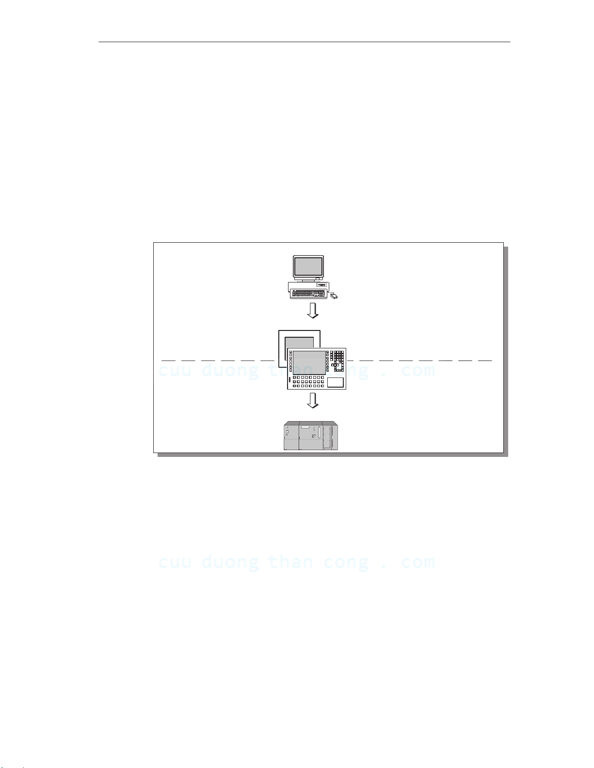
Operating unit configuration (principles)
Graphics, texts and operating and display elements which need to be represented
on the operating unit must first be created on a configuration computer (PC or PU)
using the configuration software. The configuration computer must be connected to
the operating unit in order to download the project to the operating unit (refer to
“Configuration phase” in Figure 1-1).
Once the project has been successfully downloaded, connect the operating unit to
the PLC. The operating unit can then communicate with the PLC and respond
according to the information configured for running the program in the PLC (refer to
“Process control phase” in Figure 1-1).
Configuration phase
Operating unit
Introduction
PC/ PU
Create project data
Store project data
T est project
Simulate project
Download project data
TP
OP
Connected to PLC
PLC
Figure 1-1 Configuration and process control phase
TP 170A Equipment Manual
Release 12/99
CuuDuongThanCong.com https://fb.com/tailieudientucntt
1-3
Introduction
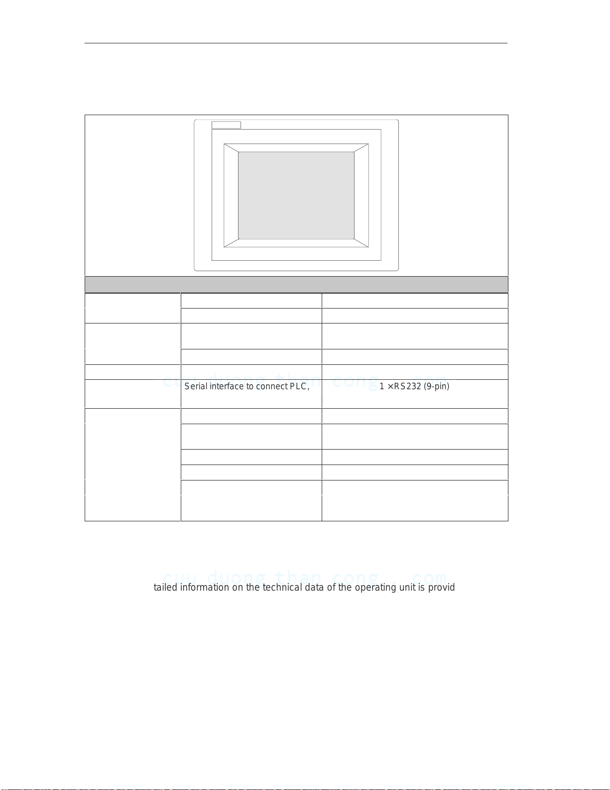
Overview of the TP 170A
Overview: Model TP 170A
Processor
Memory
Software Operating system MicrosoftR WindowsR CE
Interfaces Serial interface to connect PLC,
Display
1) Refer to the Glossary for a definition.
Type 32 bit RISC
Clock frequency 66 MHz
Flash EPROM for operating
system and configuration
Working memory 8 MB
PC/PU
Type STN LCD/Blue mode
Active screen area
(B × H) in mm
Resolution (pixels) 320 × 240
Monochrome 4-level
Back-lighting CCFL tube
Half Brightness Life1)
approx. (hr)
2 MB
1 × RS232 (9-pin)
1 × RS422/RS485
1 16 × 87 (5.7’ ’)
50,000
Further information
Detailed information on the technical data of the operating unit is provided in
Appendix A of this manual.
Information on the configuration of the operating unit is provided in the
ProTool Configuring Windows-based Systems
Connection of the operating unit to the PLC is described in the
Communication for Windows-based Systems
New information, for which there was insufficient time to include in the manuals, is
contained in the file README.WRI on the SIMATIC ProTool/Pro CD.
1-4
CuuDuongThanCong.com https://fb.com/tailieudientucntt
user’s guide.
user’s guide.
TP 170A Equipment Manual
Release 12/99
Functionality
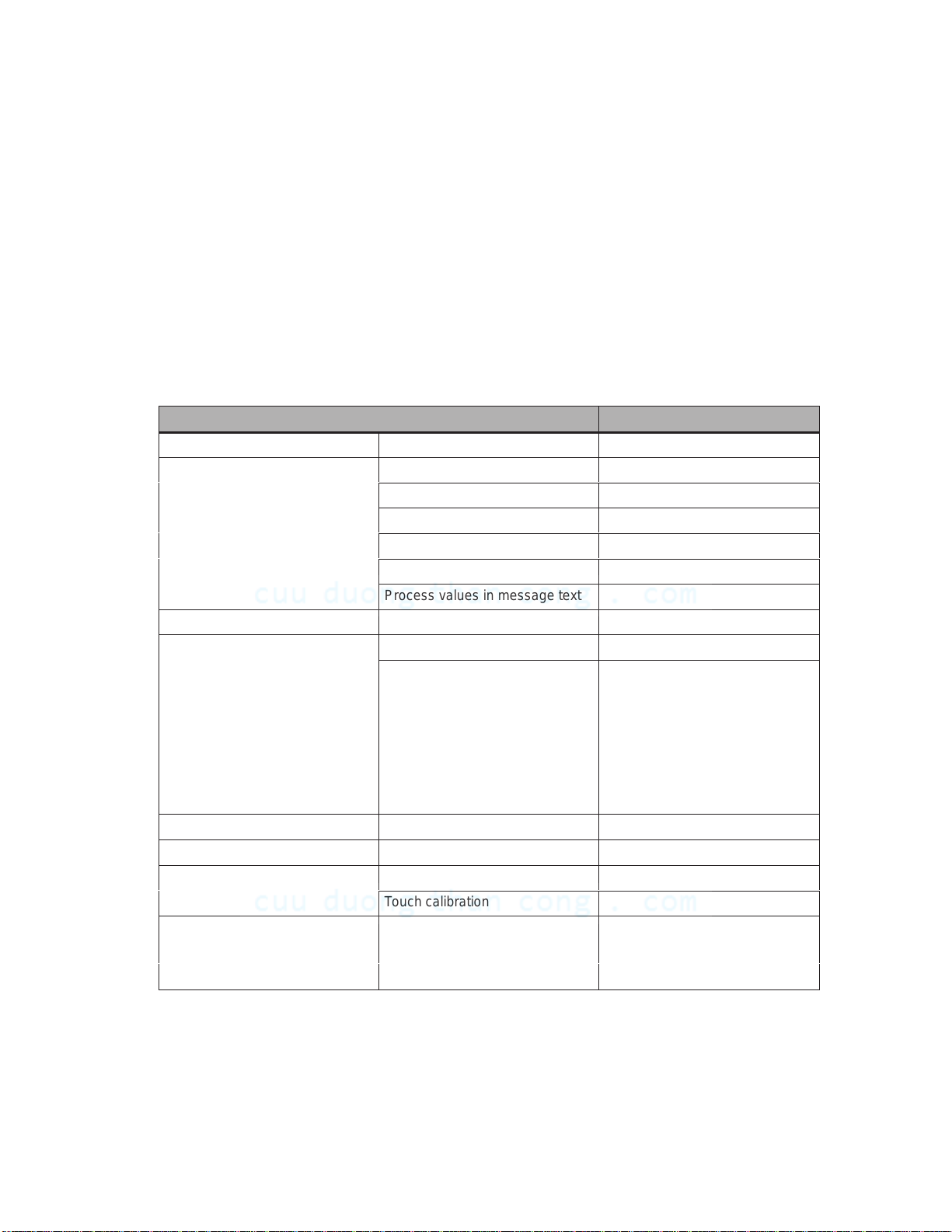
The table below summarizes the functional scope of the operating unit. The values quoted are
the maximum values which can be managed by the operating unit. The values are limited by the
size of the memory used.
Function Comment
Configuration memory Capacity , in kByte 256
Messages Number 100
Display In message display
Type of display First/Last
Message text length 70 characters
Pending message events 16
Process values in message text 8
Message acquisition Time of occurrence Date and time
Screens View 4
Screen objects Output field
2
Input field
Text
Graphics
Status button
Bar
Message view
Limit value monitoring Inputs/outputs 4
Password protection Passwords 1
Screen settings Contrast 4
Touch calibration 4
Communication SIMATIC S7
MPI (to 1.5 Mbits/s) 4
PROFIBUS-DP 4
TP 170A Equipment Manual
Release 12/99
CuuDuongThanCong.com https://fb.com/tailieudientucntt
2-1

Functionality
2-2
TP 170A Equipment Manual
CuuDuongThanCong.com https://fb.com/tailieudientucntt
Release 12/99

Commissioning
In this chapter
This chapter provides information on:
starting up the operating unit for the first time (Page 3-2)
restarting the operating unit (from Page 3-3)
the options for Download mode (from Page 3-5)
testing a configuration (Page 3-7)
3
TP 170A Equipment Manual
Release 12/99
CuuDuongThanCong.com https://fb.com/tailieudientucntt
3-1
Commissioning
3.1 Initial Startup
Procedure
When the operating unit is started up for the first time, there is no configuration
loaded. Proceed as follows, observing the sequence, in order to download a
configuration from the configuration computer to the operating unit which is
necessary to put the unit into service:
Step Procedure
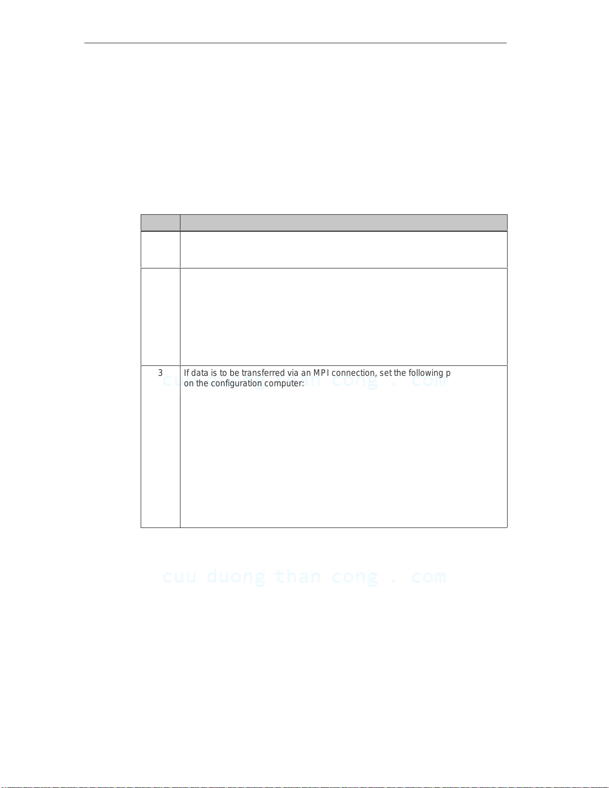
1 Connect the interface IF1A (RS232) or IF1B (RS485) on the operating unit to the
configuration computer, according to the setting in the Configuration menu
(Figure 3-2, Page 3-5), using an appropriate standard cable.
2 Switch on the power supply for the operating unit.
Since no configuration has been loaded at this point, the operating unit
automatically switches to Download mode. The operating unit displays the
message Connecting to host until it receives data from the configuration
computer or the button
If the message Connecting to host does not appear, it is possible that the
option for Download mode has been set incorrectly (refer to the note on
Page 3-6).
3 If data is to be transferred via an MPI connection, set the following parameters
on the configuration computer:
OP Address: 1
Transmission rate: 187.5 kBaud
Start the data transfer to the operating unit from the configuration computer.
The configuration computer checks the connection to the operating unit. If the
connection is not available or defective, it issues the corresponding error
message.
If downloading from the configuration computer is interrupted due a compatibility
conflict, please proceed according to the description in the Chapter 10.
If the connection is correct, the configuration is downloaded to the operating unit.
Following successful downloading, the operating unit restarts and displays the
start screen of the configuration that has just been loaded.
Cancel
is pressed.
3-2
TP 170A Equipment Manual
CuuDuongThanCong.com https://fb.com/tailieudientucntt
Release 12/99
Commissioning
3.2 Recommissioning
Purpose
Following a restart, the configuration in the operating unit is replaced by a different
one. The new configuration is downloaded from the configuration computer to the
operating unit.
The following options are available for downloading a configuration:
Start downloading manually during the operating unit initialization phase
Start downloading automatically while the operating unit is in operation
Start downloading via a correspondingly configured operating element while the
operating unit is in operation (refer to the Chapter 6.1)
Start downloading manually during the operating unit initialization phase
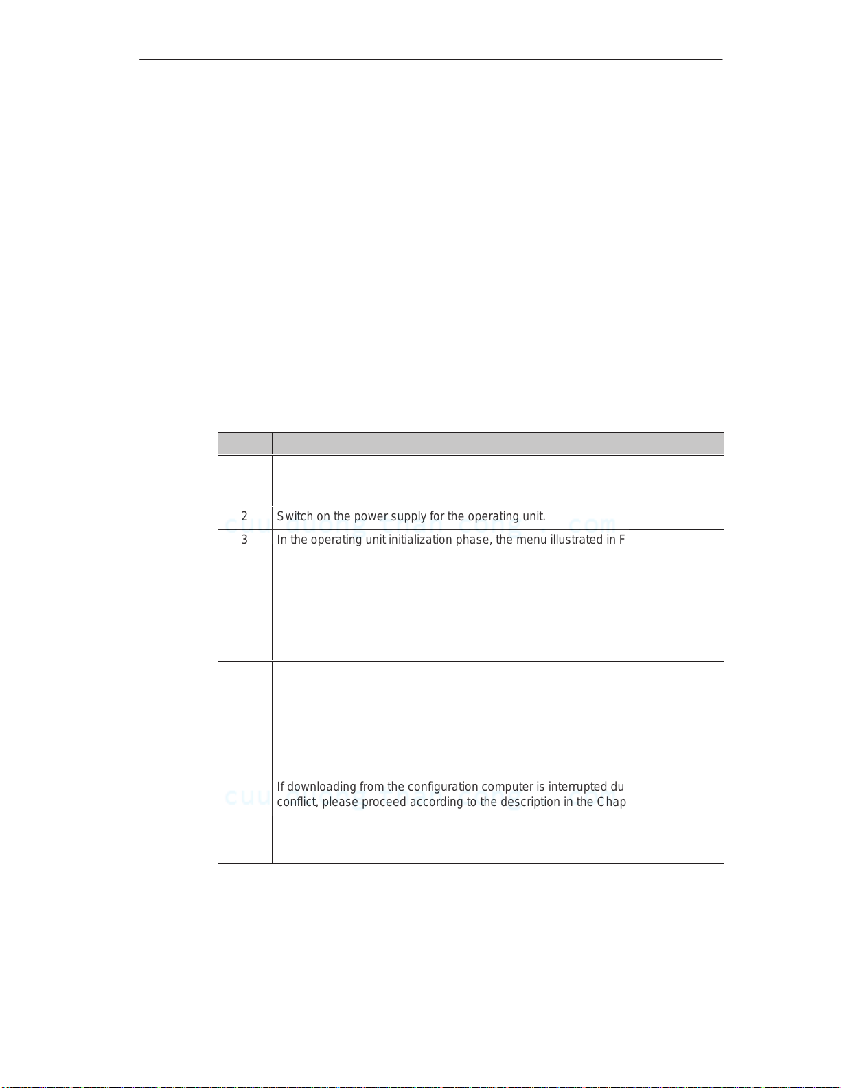
Step Procedure
1 Connect the interface IF1A (RS232) or IF1B (RS485) on the operating unit to the
configuration computer, according to the setting in the Configuration menu
(Figure 3-2, Page 3-5), using an appropriate standard cable.
2 Switch on the power supply for the operating unit.
3 In the operating unit initialization phase, the menu illustrated in Figure 3-1
appears briefly . Touch the
mode before it is initialized.
The operating unit displays the message Connecting to host until it receives
data from the configuration computer or the button
If the message Connecting to host does not appear, it is possible that the
option for Download mode has been set incorrectly (refer to the note on Page
3-6).
4 If downloading should be performed via an MPI connection, set the OP address
and transmission rate valid for the operating unit on the configuration computer
(refer to the note on Page 3-4).
Start data transfer to the operating unit from the configuration computer.
The configuration computer checks the connection to the operating unit. If the
connection is not available or defective, the configuration computer issues the
corresponding error message.
If downloading from the configuration computer is interrupted due a compatibility
conflict, please proceed according to the description in the Chapter 10.
If the connection is correct, the new configuration is downloaded to the operating
unit. Following successful downloading, the operating unit restarts and displays
the start screen of the configuration that has just been loaded.
Download
button to set the operating unit to Download
Cancel
is pressed.
TP 170A Equipment Manual
Release 12/99
CuuDuongThanCong.com https://fb.com/tailieudientucntt
3-3

Commissioning
Start downloading automatically when the operating unit is in operation
The operating unit can be switched automatically to Download mode from normal
operation as soon as downloading is started on the connected configuration
computer. This option is especially recommended for the test phase of a new
configuration because the transfer is performed without intervention in the
operating unit. A condition for this is that the following settings are defined in the
Configuration menu (Figure 3-2):
MPI connection:
Option
Option
MPI Transfer Enable
MPI Transfer Remote
activated
activated
Serial connection:
Option
Option
Serial Transfer Enable
Serial Transfer Remote
activated
activated
A detailed description of the possible settings in the Configuration menu is
provided on Page 3-5.
Note:
The bus parameters (e.g. MPI address, baud rate, etc.) are read out of the
configuration which has been loaded on the operating unit. Important: A new
project with new parameters must initially be loaded on the operating unit with the
old settings (on the configuration computer) because the old parameters apply
here.
3-4
TP 170A Equipment Manual
CuuDuongThanCong.com https://fb.com/tailieudientucntt
Release 12/99
3.3 Download Mode Options
Purpose
The following options can be set for Download mode:
The operating unit can be switched from normal operation to Download mode
automatically as soon as downloading is started on the connected configuration
computer.
Download mode can be restricted to a specific connection type so that
downloading is only performed via a serial or an MPI connection.
Call in the Configuration menu
The options for Download mode can only be set when the operating unit is in its
initialization phase. During the operating unit initialization phase, the Start menu,
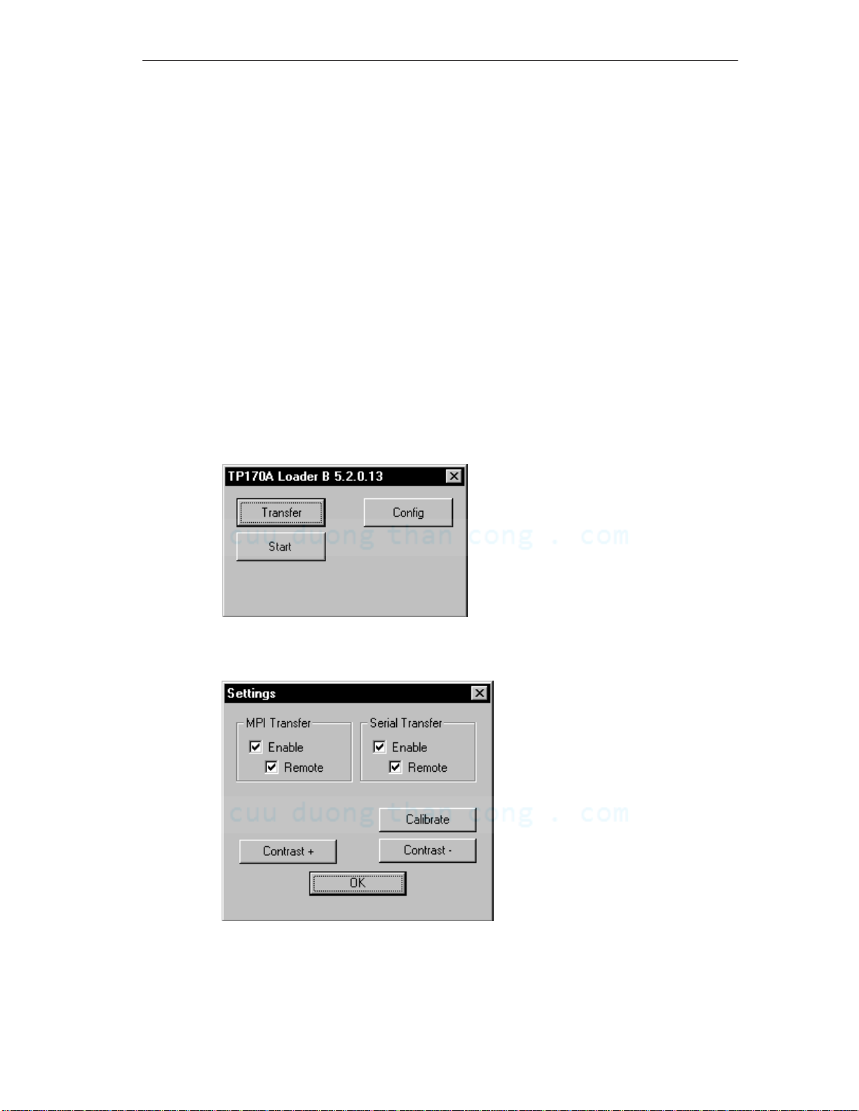
illustrated in Figure 3-1 appears briefly. Touch the
Configuration menu displayed in Figure 3-2.
Config
button to call in the
Commissioning
Figure 3-1 TP 170A Start menu
Figure 3-2 Configuration menu
TP 170A Equipment Manual
Release 12/99
3-5
CuuDuongThanCong.com https://fb.com/tailieudientucntt

Commissioning
Define settings
The downloading options defined in the Configuration menu have the following
effects:
Option
MPI Transfer Enable
If this option is deactivated, the operating unit does not permit downloading via
an MPI connection (refer to the Note below).
Option
This option is only available for selection when the
MPI Transfer Remote
MPI Transfer Enable
option
is active.
When this option is active, the operating unit automatically switches from
normal operation to Download mode in the case of an MPI transfer from the
configuration computer.
Option
Serial Transfer Enable
If this option is deactivated, the operating unit does not permit downloading via
a serial connection (refer to the Note below).
Option
This option is only available for selection when the
Serial Transfer Remote
Serial Transfer Enable
option
is active.
When this option is active, the operating unit automatically switches from
normal operation to Download mode in the case of serial transfer from the
configuration computer.
Use the OK button to confirm the current settings for downloading options. The
Configuration menu is closed and the Start menu illustrated in Figure 3-1 is
displayed.
Note:
If both the options
MPI Transfer Enable
and
Serial Transfer Enable
are
deactivated, it is not possible to download a configuration from the configuration
computer to the operating unit.
Exit the Start menu
If no configuration is loaded on the operating unit, it switches to Download mode
automatically after 10 seconds. Touch the
unit to Download mode manually.
If a configuration has already been loaded on the operating unit, it starts it up
automatically after 10 seconds. The configuration can be started manually by
touching the
3-6
CuuDuongThanCong.com https://fb.com/tailieudientucntt
Start
button.
Download
button to switch the operating
TP 170A Equipment Manual
Release 12/99

3.4 T est Configuration
Simulation on a configuration computer
A simulator is supplied with the configuration software which can be used to test
your configuration without the necessity of a connection to a PLC. A condition for
this is that the runtime software is installed on the same configuration computer on
which the configuration software is loaded. The runtime software is contained on
the configuration software installation CD.
The simulator is an individual application. It simulates the configuration offline, i.e.
without the necessity of a physical connection to a PLC. The PLC is simulated by
the software.
Start the simulator by clicking on the symbol depicted on the left or by using
the menu command
File → Test → Start simulator
Commissioning
.
Detailed information on operating the simulator is provided in the
Configuring Windows-based Systems
software online help.
Note:
For the test phase of a configuration, it is recommended to initiate Download mode
from normal operation automatically. Further information is available on Page 3-4.
Test with connected PLC
When a PLC is connected, it is possible to test the communication between the
operating unit and PLC. This test also determines whether the correct data areas
have been configured.
Check the following configuration elements, for example:
messages,
screen selection,
input field.
ProTool
user’s guide and in the configuration
TP 170A Equipment Manual
Release 12/99
CuuDuongThanCong.com https://fb.com/tailieudientucntt
3-7

Commissioning
3-8
TP 170A Equipment Manual
CuuDuongThanCong.com https://fb.com/tailieudientucntt
Release 12/99

Operating the TP 170A
In this chapter
This chapter contains information on how to:
operate touch elements (from Page 4-2)
enter values (from Page 4-4)
operate screens (Page 4-6)
Information regarding operation for special screen objects is provided in Chapter 5.
4
TP 170A Equipment Manual
Release 12/99
CuuDuongThanCong.com https://fb.com/tailieudientucntt
4-1

Operating the TP 170A
4.1 Operating Touch Elements
Operating concept
The screen is used to observe the operating status of the machine or system being
monitored and, at the same time, to intervene directly in the process running
simply by touching the buttons and input fields displayed.
Definition
Touch elements are contact–sensitive operating elements provided on the touch
panel screen, such as buttons and input fields. Their operation is basically no
different from pressing conventional keys. Touch elements are operated by
touching them lightly with your finger or a suitable object.
Note
Never use pointed or sharp instruments to operate the Touch Panel to prevent
damage to the plastic surface of the touch screen.
Caution
!
Never touch more than one touch panel screen element at a time. If you do, an
unintended action may be initiated.
4-2
TP 170A Equipment Manual
CuuDuongThanCong.com https://fb.com/tailieudientucntt
Release 12/99
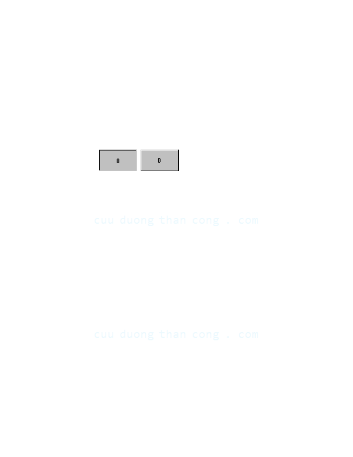
Operation acknowledgement
As soon as the touch panel detects valid contact with a touch element, it responds
by displaying a visual acknowledgement. An acknowledgment is independent of
communication with the PLC. It is not an indication of the required action actually
having been executed.
The type of visual acknowledgement is dependent on the operating element
touched:
Buttons
In the case of 3D–effect configurations, visual representation is distinguished
according to the statuses
are illustrated below by means of the Status button:
Operating the TP 170A
touched
and
untouched
. Examples of representation
UntouchedTouched
Input fields
After an input field has been touched, the system keyboard illustrated in
Figure 4-1 appears as the operation acknowledgement.
Password protected operating elements
If an operating element is touched which has been assigned with a password
protection, without the user having logged in on the operating unit beforehand, a
system message is triggered. The password protected function is not executed.
Further information on this subject is available in the Chapter 5.4.
TP 170A Equipment Manual
Release 12/99
CuuDuongThanCong.com https://fb.com/tailieudientucntt
4-3
Operating the TP 170A
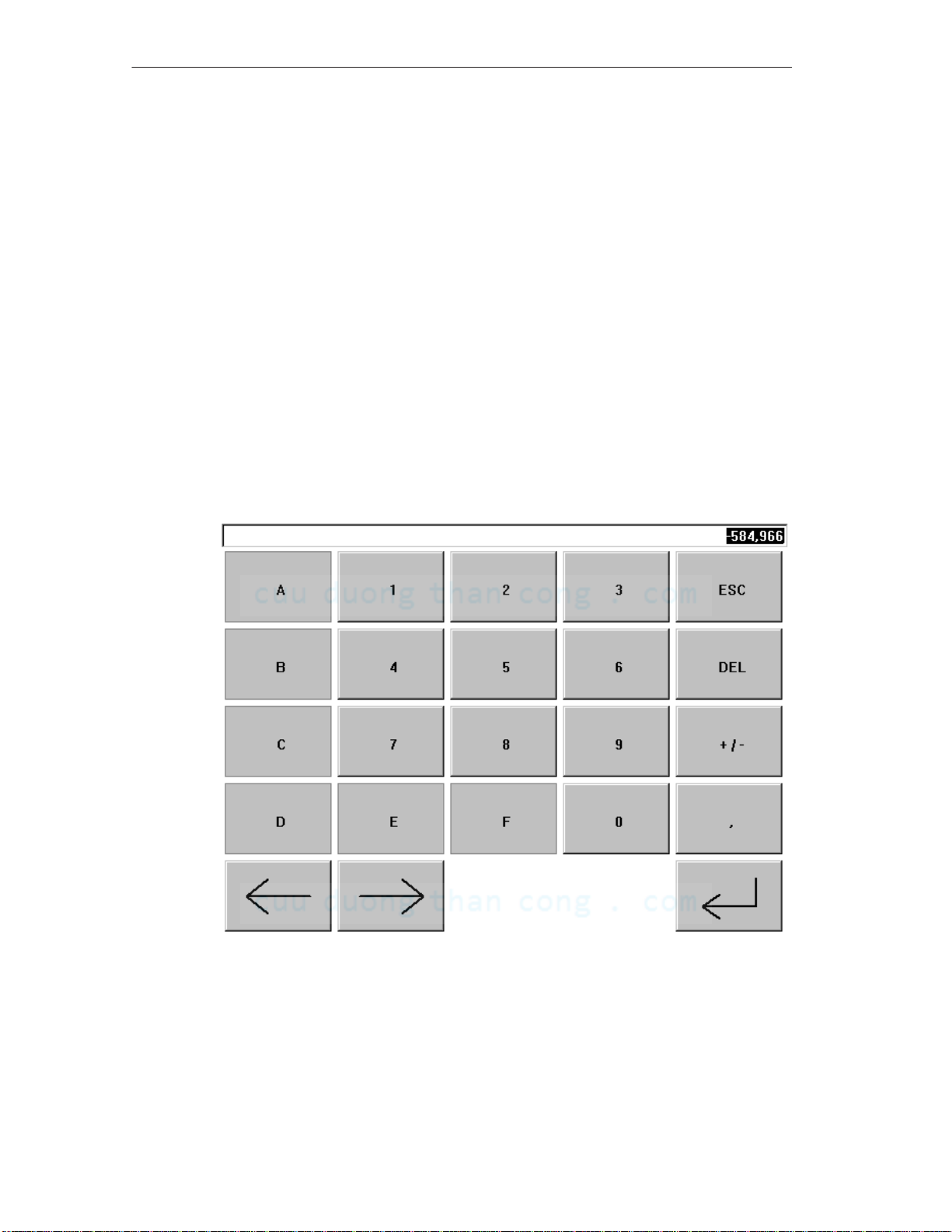
4.2 Entering Values
Principles of operation
Input fields are used to enter digits and texts (characters 0 to 9 and A to F). To do
so, touch the corresponding field. The system keyboard appears.
After an entry has been made correctly, the system keyboard automatically
disappears and the entered value is accepted in the input field.
System keyboard
The buttons available for operation on the system keyboard are dependent on the
type of value to be entered. Buttons which are available for operation are
highlighted, and those not available appear simply as empty areas.
Figure 4-1 illustrates an example of the system keyboard for entering decimal
values. Table 4-1 explains the significance of each individual button.
4-4
Figure 4-1 System keyboard
TP 170A Equipment Manual
CuuDuongThanCong.com https://fb.com/tailieudientucntt
Release 12/99
Meanings of buttons
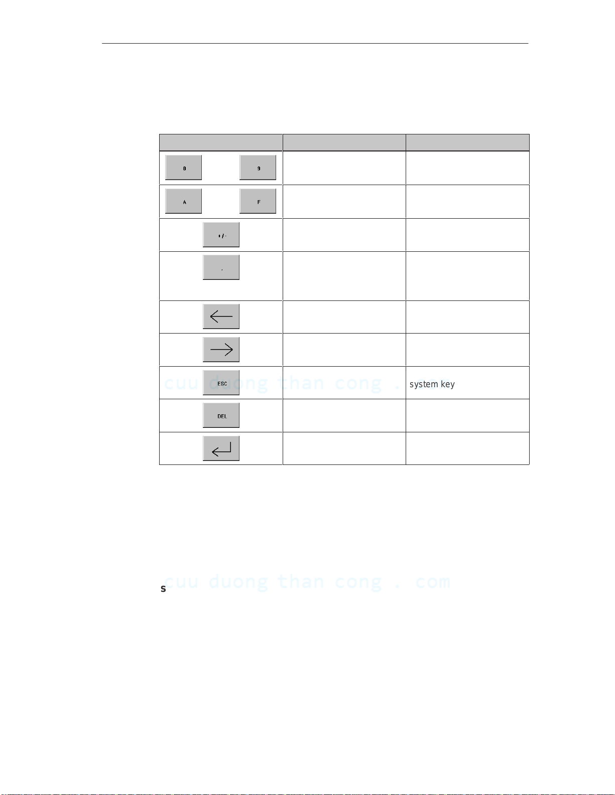
Table 4-1 Significance of buttons
Operating the TP 170A
Button Function Purpose
Enter digits Enter digits 0 to 9.
...
...
Enter characters Enter the characters A to F.
Change sign Change sign from + to – and
back.
Enter decimal point Enter decimal point or
comma. The assignment
and labeling of this button is
language–dependent.
Move input position
to the left
Move input position
to the right
Cancel (Escape) Discard input and close the
Delete character Delete the character to the
Enter Confirm input and close the
Move current input position
one character to the left.
Move current input position
one character to the right.
system keyboard.
left of the input position.
system keyboard.
Enter value
Characters entered are aligned to the right. On entering a new character, all those
already entered are shifted one position to the left (pocket calculator format).
On exceeding the maximum number of characters, the last character entered is
overwritten.
Limit values
Limit values can be configured for numeric input fields. In this case, values
entered are only accepted when they lie within the limits configured.
Note:
If an attempt is made to enter a value which is outside the configured limit values,
the system keyboard is closed and the original value reinserted. In addition, a
system message is triggered.
TP 170A Equipment Manual
Release 12/99
4-5
CuuDuongThanCong.com https://fb.com/tailieudientucntt

Operating the TP 170A
4.3 Operating Screens
What is a screen?
Screens visualize the progress of processes and display specified process values.
A screen contains logically related process data which the operating unit can both
display and modify by operating the individual values.
Screen partitions
A screen is basically composed of static and dynamic sections. The terms “static”
and “dynamic” do not refer to the possibility of dynamically positioning screen
partitions but to the connection to the PLC.
Static partitions, e.g. text and graphics, are not updated by the PLC. Dynamic
partitions, e.g. input and output fields and bars, can be linked to the PLC and
display current values constantly read in from the PLC memory. Their connection
to the PLC is established by means of tags.
Screen objects
Various screen elements are used to display and operate a screen:
Output fields
Input fields
Texts
Graphics
Status buttons
Bar graphs
Message view
A summary of all the screen objects which a TP 170A project may contain is
provided in Chapter 5.
4-6
TP 170A Equipment Manual
CuuDuongThanCong.com https://fb.com/tailieudientucntt
Release 12/99
 Loading...