

Siemens SIMATIC HMI TP1000F Mobile RO Operating Instructions Manual

___________________
___________________
___________________
___________________
___________________
___________________
___________________
___________________
___________________
___________________
___________________
___________________
SIMATIC HMI
HMI devices
TP1000F Mobile RO
Operating Instructions
08/2017
A5E39831415
Preface
Overview
1
Safety instructions
2
Installing system
components
3
Handling the Mobile Panel
4
Parameterizing the Mobile
Panel
5
Using a client
6
Fail-safe operation
7
Maintenance and care
8
Technical specifications
9
Technical Support
A
List of abbreviations
B
-AA
Siemens AG
Division Digital Factory
Postfach 48 48
90026 NÜRN
GERMANY
A5E39831415-AA
Ⓟ
Copyright © Siemens AG 2017.
All rights reserved
Legal information
Warning notice system
DANGER
indicates that death or severe personal injury will result if proper precautions are not taken.
WARNING
indicates that death or severe personal injury may result if proper precautions are not taken.
CAUTION
indicates that minor personal injury can result if proper precautions are not taken.
NOTICE
indicates that property damage can result if proper precautions are not taken.
Qualified Personnel
personnel qualified
Proper use of Siemens products
WARNING
Siemens products may only be used for the applications described in the catalog and in the relevant technical
ce are required to ensure that the products operate safely and without any problems. The permissible
ambient conditions must be complied with. The information in the relevant documentation must be observed.
Trademarks
Disclaimer of Liability
This manual contains notices you have to observe in order to ensure your personal safety, as well as to prevent
damage to property. The notices referring to your personal safety are highlighted in the manual by a safety alert
symbol, notices referring only to property damage have no safety alert symbol. These notices shown below are
graded according to the degree of danger.
If more than one degree of danger is present, the warning notice representing the highest degree of danger will
be used. A notice warning of injury to persons with a safety alert symbol may also include a warning relating to
property damage.
The product/system described in this documentation may be operated only by
task in accordance with the relevant documentation, in particular its warning notices and safety instructions.
Qualified personnel are those who, based on their training and experience, are capable of identifying risks and
avoiding potential hazards when working with these products/systems.
Note the following:
documentation. If products and components from other manufacturers are used, these must be recommended
or approved by Siemens. Proper transport, storage, installation, assembly, commissioning, operation and
maintenan
All names identified by ® are registered trademarks of Siemens AG. The remaining trademarks in this publication
may be trademarks whose use by third parties for their own purposes could violate the rights of the owner.
We have reviewed the contents of this publication to ensure consistency with the hardware and software
described. Since variance cannot be precluded entirely, we cannot guarantee full consistency. However, the
information in this publication is reviewed regularly and any necessary corrections are included in subsequent
editions.
for the specific
BERG
09/2017 Subject to change

Preface
Purpose and knowledge
Purpose of the operating instructions
Basic knowledge required
Scope and brands
Scope of the document
These operating instructions contain information based on the requirements defined by DIN
EN 62079 for mechanical engineering documentation. This information relates to the place of
use, transport, storage, mounting, use and maintenance.
These operating instructions are intended for:
● Users
● Commissioning engineers
● Maintenance personnel
General knowledge of automation technology and process communication is needed to
understand the operating instructions. Knowledge of personal computers and the Microsoft
operating systems is required to understand this manual.
The operating instructions apply to the following HMI device in combination with the
corresponding connection boxes and the RemoteOperate V4.0.0.1 software:
● SIMATIC HMI TP1000F Mobile RO, article number 6AV2145-6KB10-0AS0
The HMI device is technically based on the Mobile Panels 2nd Generation and is therefore
also referred to as "Mobile Panel 2nd Generation" or "HMI device of the type KTP Mobile" is
this document, see section "Conventions".
The corresponding connection boxes with article numbers and information on compatibility
can be found in the following sections:
● Connection boxes (Page 15)
● Mobile Panel and connection box compatibility (Page 24)
TP1000F Mobile RO
Operating Instructions, 08/2017, A5E39831415-AA
3

Preface
Note
This document belongs to the system
•
•
•
You will also need the document whenever the system is re
supplied and supplementary documentation for the entire service life of the Mobile Panel.
Provide any future owner or user with all the documents for the HMI
Associated documents
Conventions
Style conventions
Style Convention
Scope
"File > Edit"
Operational sequences, e.g, menu command, shortcut menu command
<F1>, <Alt+P>
Keyboard operation
Note
A note contains important information about
handling, or a specific section of the document to which you should pay particular attention.
Mobile Panel
Connection box
KTP Mobile connecting cable
-commissioned. Keep all
device.
Make sure that every supplement to the documentation that you receive is stored together
with the operating instructions.
Additional information on the RemoteOperate software is available in the
RemoteOperate V4.0.0.1 programming manual.
"Add screen"
• Terminology that appears in the user interface, for example, dialog
names, tabs, buttons, menu commands
• Necessary entries, for example, limit, tag value
• Path information
Please observe notes labeled as follows:
the product described in the document and its
TP1000F Mobile RO
4 Operating Instructions, 08/2017, A5E39831415-AA

Preface
Naming conventions
Term
Applies to
Control cabinet
Mounted cabinet, enclosure, terminal box, panel, control panel
F-system
Fail-safe automation system with fail-safe Mobile Panel
for the device
for HMI devices of the type KTP Mobile
for the device
for HMI devices of the type KTP Mobile
Mobile Panel
Fail-safe Mobile Panel
TP1000F Mobile RO
RemoteOperate Server
The RemoteOperate Server software
RemoteOperate Client
The RemoteOperate Client software
RemoteOperate
The RemoteOperate software (Server and Client)
or runs.
Client, HMI device
A system on which the RemoteOperate Client software runs.
Information on standards
Figures
Plant System, machining center, one or more machines
Connection box
Connecting cable
Wall-mounting bracket
HMI device
Safety-related operator control
Storage medium
Server A system on which the RemoteOperate Server software is installed
• Connection box compact
• Connection box standard
• Connection box advanced
Connecting cable KTP Mobile
Wall-mounting bracket KTP Mobile
TP1000F Mobile RO
• Emergency stop / stop button
• Enabling button
• SD memory card
• USB flash drive
You can find detailed information on standards including year of publication and
corresponding supplements in the section "Standards on operating safety (Page 156)".
Standards and supplements will be referenced in the remainder of the document without
citation of the year of publication, for example, "EN 61000-6-4 +A1".
This document contains figures of the devices described. The figures can deviate from the
particularities of the delivered device.
TP1000F Mobile RO
Operating Instructions, 08/2017, A5E39831415-AA
5

Preface
TP1000F Mobile RO
6 Operating Instructions, 08/2017, A5E39831415-AA

Table of contents
Preface ................................................................................................................................................... 3
1 Overview............................................................................................................................................... 11
2 Safety instructions ................................................................................................................................. 25
3 Installing system components ............................................................................................................... 35
1.1 Product overview .................................................................................................................... 11
1.2 Design of the Mobile Panel ..................................................................................................... 12
1.3 KTP Mobile connecting cable ................................................................................................. 14
1.4 Connection boxes ................................................................................................................... 15
1.5 Scope of delivery .................................................................................................................... 18
1.6 Accessories ............................................................................................................................. 19
1.6.1 Overview ................................................................................................................................. 19
1.6.2 KTP Mobile wall-mounting bracket ......................................................................................... 19
1.6.3 Touch pens ............................................................................................................................. 20
1.6.4 Storage media ......................................................................................................................... 20
1.6.5 SIRIUS safety relay ................................................................................................................. 20
1.7 The HMI device in the operating process ............................................................................... 21
1.8 Terms for fail-safe operation ................................................................................................... 22
1.9 Organizational measures ........................................................................................................ 24
1.10 Mobile Panel and connection box compatibility ...................................................................... 24
2.1 General safety instructions ..................................................................................................... 25
2.2 Notes about usage .................................................................................................................. 30
2.3 Risk analysis of the plant ........................................................................................................ 31
2.4 Important information on emergency stop / stop button ......................................................... 31
2.5 Important notes for the enabling mechanism ......................................................................... 33
3.1 Checking the scope of delivery ............................................................................................... 35
3.2 Mounting the connection box compact ................................................................................... 35
3.2.1 Mounting position, mounting cutout and clearance ................................................................ 35
3.2.2 Fastening the connection box compact .................................................................................. 37
3.3 Installing the connection box standard and connection box advanced .................................. 37
3.3.1 Mounting position and clearance ............................................................................................ 37
3.3.2 Fastening the connection box standard and connection box advanced ................................. 38
3.4 Attaching the KTP Mobile wall-mounting bracket ................................................................... 39
3.4.1 Assembling the KTP Mobile wall-mounting bracket ............................................................... 39
3.4.2 Mounting position and clearance ............................................................................................ 40
3.4.3 Fasteneing the KTP Mobile wall-mounting bracket ................................................................ 42
3.5 Connecting the Mobile Panel .................................................................................................. 43
3.5.1 Connection information ........................................................................................................... 43
3.5.2 Inserting the SD memory card ................................................................................................ 43
3.5.3 Connecting the Mobile Panel connecting cable ...................................................................... 45
TP1000F Mobile RO
Operating Instructions, 08/2017, A5E39831415-AA
7

Table of contents
4 Handling the Mobile Panel .................................................................................................................... 65
5 Parameterizing the Mobile Panel ........................................................................................................... 73
3.5.4 Connecting PC and server ..................................................................................................... 46
3.5.5 Replacing the connecting cable ............................................................................................. 47
3.5.6 Replacing an SD memory card .............................................................................................. 48
3.5.7 Inserting the USB memory stick ............................................................................................. 49
3.6 Connecting the connection box .............................................................................................. 50
3.6.1 Connection information .......................................................................................................... 50
3.6.2 Opening and closing connection box standard and connection box advanced ..................... 51
3.6.3 Equipotential bonding of connection boxes ........................................................................... 53
3.6.4 Connecting the functional grounding and power supply to the connection box .................... 55
3.6.5 Connecting cables for a hardwired F-system ........................................................................ 57
3.6.6 Connecting Ethernet to the connection box ........................................................................... 58
3.6.7 Setting the box ID of the connection box ............................................................................... 61
3.6.8 Secure cables and seal screw glands ................................................................................... 63
3.7 Connecting the KTP Mobile connecting cable to the connection box.................................... 64
4.1 Holding the Mobile Panel and attaching it to the wall-mounting bracket ............................... 65
4.2 Operating the enabling button ................................................................................................ 67
4.3 Pressing the emergency stop / stop button ........................................................................... 68
4.4 Testing Mobile Panel readiness for operation ....................................................................... 70
5.1 Desktop and Start Center ...................................................................................................... 73
5.2 Operating the desktop, Start Center and Control Panel ........................................................ 74
5.3 Installed programs ................................................................................................................. 74
5.4 Security mode ........................................................................................................................ 75
5.4.1 Overview ................................................................................................................................ 75
5.4.2 Using the HMI device in password-protected security mode ................................................. 75
5.5 Control Panel ......................................................................................................................... 76
5.5.1 Opening the settings .............................................................................................................. 76
5.5.2 Overview of functions ............................................................................................................. 77
5.5.3 Operating the Control Panel .................................................................................................. 78
5.5.4 Display types for the screen keyboard ................................................................................... 79
5.6 Configuring operation ............................................................................................................. 81
5.6.1 Changing display brightness .................................................................................................. 81
5.6.2 Configuring the screen keyboard ........................................................................................... 82
5.6.3 Setting the character repeat rate of the screen keyboard ..................................................... 83
5.6.4 Setting the double-click .......................................................................................................... 84
5.6.5 Calibrating the touch screen .................................................................................................. 85
5.6.6 Restarting the HMI device ...................................................................................................... 86
5.7 General settings ..................................................................................................................... 88
5.7.1 Regional and language settings............................................................................................. 88
5.7.2 Setting the date and time ....................................................................................................... 89
5.7.3 Entering and deleting a password.......................................................................................... 90
5.7.4 Setting the screen saver ........................................................................................................ 92
5.7.5 Configuring transfer ............................................................................................................... 94
5.7.6 Storage management ............................................................................................................ 95
5.7.6.1 Displaying memory distribution .............................................................................................. 95
5.7.6.2 Setting the delay time ............................................................................................................ 96
TP1000F Mobile RO
8 Operating Instructions, 08/2017, A5E39831415-AA

Table of contents
6 Using a client ...................................................................................................................................... 131
7 Fail-safe operation .............................................................................................................................. 149
8 Maintenance and care ......................................................................................................................... 151
9 Technical specifications ...................................................................................................................... 155
5.7.7 Backing up registry information and temporary data .............................................................. 98
5.7.8 Displaying general system properties ..................................................................................... 99
5.7.9 Displaying information about the Mobile Panel ...................................................................... 99
5.7.10 Display firmware ................................................................................................................... 100
5.8 Changing Internet settings .................................................................................................... 101
5.8.1 Changing general settings .................................................................................................... 101
5.8.2 Setting the proxy server ........................................................................................................ 102
5.8.3 Changing Internet security settings ...................................................................................... 103
5.8.4 Activating encryption protocols ............................................................................................. 105
5.8.5 Importing, displaying and deleting certificates ...................................................................... 106
5.9 Checking the PROFINET IO settings ................................................................................... 108
5.10 Server time ............................................................................................................................ 109
5.11 Configuring network operation .............................................................................................. 111
5.11.1 Overview ............................................................................................................................... 111
5.11.2 Specifying the computer name of the HMI device ................................................................ 112
5.11.3 Specifying the IP address and name server ......................................................................... 113
5.11.4 Specifying the logon data ..................................................................................................... 114
5.12 Assigning a safety-related operating mode .......................................................................... 115
5.13 Functions for service and commissioning ............................................................................. 117
5.13.1 Saving to external storage medium – backup ....................................................................... 117
5.13.2 Restoring from external storage medium – Restore ............................................................. 120
5.13.3 Backing up and restoring data (ProSave) ............................................................................. 123
5.13.4 Updating the HMI device image (ProSave) .......................................................................... 125
5.13.5 Using automatic backup........................................................................................................
127
6.1 Creating/editing a server selection list .................................................................................. 131
6.2 Connect client ....................................................................................................................... 135
6.3 Closing the RemoteOperate Client ....................................................................................... 139
6.4 Changing the server.............................................................................................................. 141
6.5 Example: Assigning operator authorization .......................................................................... 142
6.6 Alarm window ........................................................................................................................ 146
7.1 Connecting the connecting cable .......................................................................................... 149
7.2 Unplugging the connecting cable .......................................................................................... 150
8.1 Replacing the Mobile Panel .................................................................................................. 151
8.2 Servicing the Mobile Panel ................................................................................................... 151
8.3 Maintaining the Mobile Panel ................................................................................................ 152
8.4 Replacing the touch pen ....................................................................................................... 153
8.5 Spare parts and repairs ........................................................................................................ 154
8.6 Recycling and disposal ......................................................................................................... 154
9.1 Certificates and approvals .................................................................................................... 155
TP1000F Mobile RO
Operating Instructions, 08/2017, A5E39831415-AA
9

Table of contents
A Technical Support ................................................................................................................................ 183
B List of abbreviations ............................................................................................................................. 185
Glossary .............................................................................................................................................. 187
Index ................................................................................................................................................... 189
9.2 Standards on operating safety ............................................................................................. 156
9.3 Electromagnetic compatibility .............................................................................................. 157
9.3.1 Electromagnetic compatibility .............................................................................................. 157
9.3.2 Emitted interference ............................................................................................................. 159
9.3.3 Immunity to interferences ..................................................................................................... 159
9.4 Mechanical ambient conditions ............................................................................................ 159
9.4.1 Transport and storage conditions ........................................................................................ 159
9.4.2 Operating Conditions ........................................................................................................... 159
9.5 Climatic ambient conditions ................................................................................................. 160
9.5.1 Transport and storage conditions ........................................................................................ 160
9.5.2 Operating Conditions ........................................................................................................... 160
9.6 Dimension drawings ............................................................................................................. 161
9.6.1 TP1000F Mobile RO dimension drawing ............................................................................. 161
9.6.2 Connection box compact dimension drawing ...................................................................... 162
9.6.3 Dimension drawing for connection box standard and connection box advanced ................ 163
9.6.4 KTP Mobile wall-mounting bracket dimension drawing ....................................................... 164
9.7 Technical specifications ....................................................................................................... 165
9.7.1 Mobile Panel ........................................................................................................................ 165
9.7.2 Connecting cable ................................................................................................................. 167
9.7.3 Connection boxes ................................................................................................................ 167
9.7.4 Power consumption specifications ....................................................................................... 170
9.7.5 Reaction times and safety characteristics for fail-safe operation ........................................ 170
9.7.6 Specification of cables to be used ....................................................................................... 173
9.8 Interface description for Mobile Panel .................................................................................
174
9.8.1 Internal interface X1 P1 ....................................................................................................... 174
9.8.2 Internal interface X80 ........................................................................................................... 174
9.8.3 External interface X61 .......................................................................................................... 174
9.9 Connection box compact interfaces ..................................................................................... 175
9.9.1 Position of the interfaces ...................................................................................................... 175
9.9.2 Interface X1 .......................................................................................................................... 175
9.9.3 Plug-in terminal strip X10 ..................................................................................................... 176
9.9.4 Wiring of safety-related operator controls ............................................................................ 176
9.10 Interfaces of the connection box standard and connection box advanced .......................... 178
9.10.1 Position of the interfaces ...................................................................................................... 178
9.10.2 Fast connector X1 and X2 ................................................................................................... 179
9.10.3 Plug-in terminal strip X10 ..................................................................................................... 179
9.10.4 Wiring of safety-related operator controls ............................................................................ 180
A.1 Troubleshooting ................................................................................................................... 183
A.2 Service and support ............................................................................................................. 184
B.1 List of abbreviations ............................................................................................................. 185
TP1000F Mobile RO
10 Operating Instructions, 08/2017, A5E39831415-AA
1
1.1
Product overview
The second generation of SIMATIC HMI Mobile Panels offers direct mobile operation and
monitoring of the production process. The Mobile Panels 2nd Generation system consists of
a Mobile Panel, connection box and connecting cable.
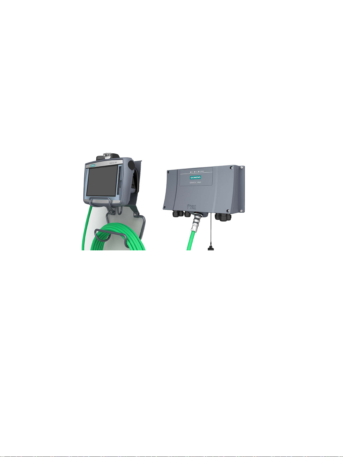
The TP1000F Mobile RO has a 10" display in widescreen format.
The figure below shows a fail-safe Mobile Panel connected to a connection box advanced.
With a fail-safe Mobile Panel, you run the plant in fail-safe mode. You meet the requirements
of Safety Integrity Level 3 and Performance Level PL e with a fail-safe Mobile Panel. An
emergency stop / stop switch and an enabling button are integrated in a fail-safe Mobile
Panel 2nd Generation. You can evaluate the safety-related operator controls in a hard-wired
F-system using safety relays.
You can choose from three connection boxes each with a different range of functions. The
connection box compact is designed for installation in control cabinets. The connection box
standard and connection box advanced are approved for external mounting directly on the
machine.
The device is designed for industrial use:
● High fall resistance
● High protection class
● High impact resistance
● High chemical resistance to operating and cleaning agents.
The enclosure type protects the emergency stop / stop button. Two protective bumpers to
prevent damage to the emergency stop / stop button during a fall of the HMI device.
TP1000F Mobile RO
Operating Instructions, 08/2017, A5E39831415-AA
11
Overview
1.2
Design of the Mobile Panel
SIMATIC HMI
Number
of function keys
Illuminated
pushbutton
Emergency stop button,
enabling button
Keyswitch
TP1000F Mobile RO
0 0 Yes
No
Note
System components
You need the following for ope
•
•
•
•
You can find the ordering information for the
(
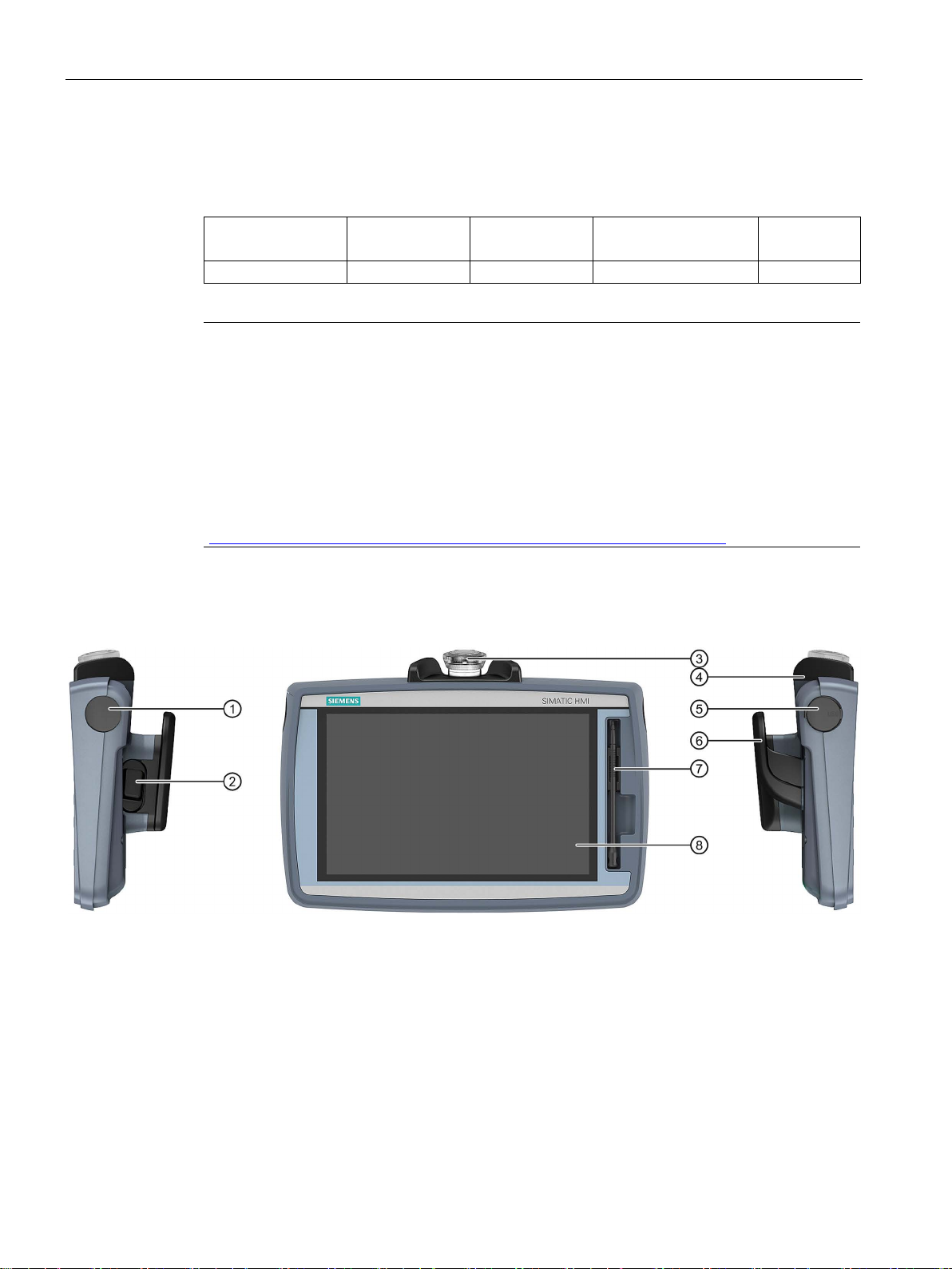
Front and side views
①
Cover (no key switch)
②
Enabling button
③
Emergency stop / stop button
④
Fall protection for the emergency stop / stop button
⑤
Cover cap for USB port
⑥
Handle
⑦
Holder with touch pen
⑧
Display with touch screen
1.2 Design of the Mobile Panel
The Mobile Panel with 10" display contains the following:
ration:
An HMI device
A connecting cable (Page 14)
At least one connection box (Page 15)
For hardwired F-systems: A safety relay (Page 20)
system components on the Internet
https://mall.industry.siemens.com/mall/en/de/Catalog/Products/10165537).
The following figures show the design of the HMI device.
TP1000F Mobile RO
12 Operating Instructions, 08/2017, A5E39831415-AA
Overview
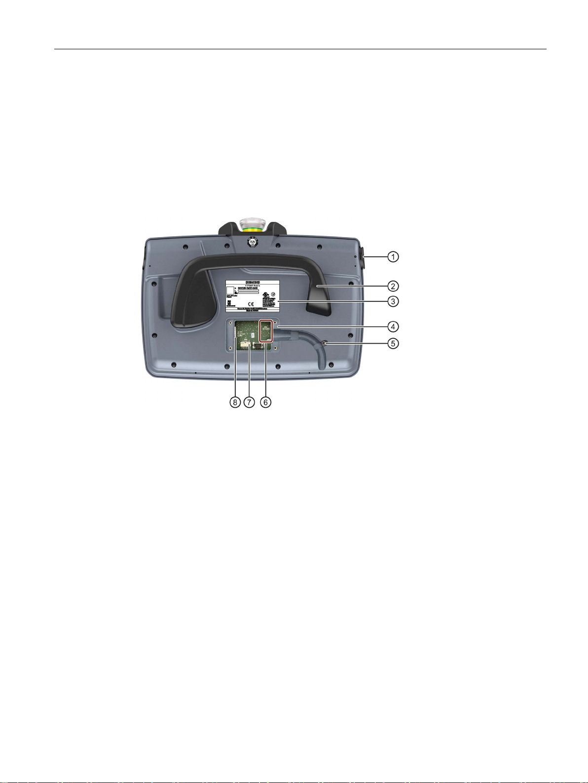
Rear view and interfaces
①
USB port with cover
⑤
Threaded sleeve for fixing screw of the cable retainer
②
Handle
⑥
Slot for an SD memory card
③
Nameplate
⑦
12-pin connector for the connecting cable
④
Terminal compartment
⑧
RJ45 socket PROFINET (LAN)
1.2 Design of the Mobile Panel
The position of the emergency stop button makes it easily accessible. Due to its profiled
design, the emergency stop button is easily accessible. Two bumpers protect the emergency
stop / stop button against impact damage, for example, if it falls. The bumpers are
dimensioned so that the emergency stop / stop button can be activated during an impact.
The operator controls are described in the section "Handling the Mobile Panel (Page 65)".
The following figure shows the layout of the HMI device.
TP1000F Mobile RO
Operating Instructions, 08/2017, A5E39831415-AA
13
Overview
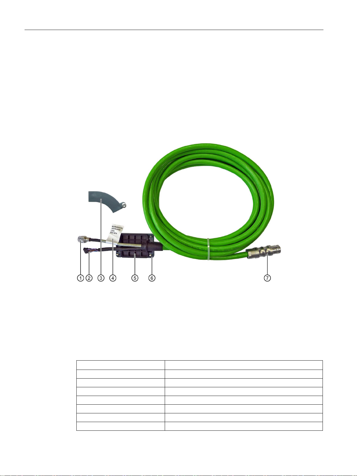
1.3
KTP Mobile connecting cable
①
RJ45 connector
②
Plug connector, 12-pin
③
Retainer, not required for KTP400F Mobile.
④
Label with order number, length specification and product version
⑤
Seal
⑥
Terminal compartment cover
⑦
Plug connector for the connection box
Product name and length
Article number
KTP Mobile 2 m connecting cable
6AV2181-5AF02-0AX0
KTP Mobile 5 m connecting cable
6AV2181-5AF05-0AX0
KTP Mobile 8 m connecting cable
6AV2181-5AF08-0AX0
KTP Mobile 10 m connecting cable
6AV2181-5AF10-0AX0
KTP Mobile 15 m connecting cable
6AV2181-5AF15-0AX0
KTP Mobile 20 m connecting cable
6AV2181-5AF20-0AX0
KTP Mobile 25m connecting cable
6AV2181-5AF25-0AX0
1.3 KTP Mobile connecting cable
The connecting cable is resistant to many solvents and lubricants. The tensile and flexural
strength of the connecting cable is geared toward the actual usage conditions.
Functions of the connecting cable:
● Power supply of the Mobile Panel
● Ethernet connection between Mobile Panel and connection box
● Transmission of the signals for emergency stop / stop button and enabling button
● Transmission of the box ID
The KTP Mobile connecting cable is available in the following lengths:
TP1000F Mobile RO
14 Operating Instructions, 08/2017, A5E39831415-AA
Overview
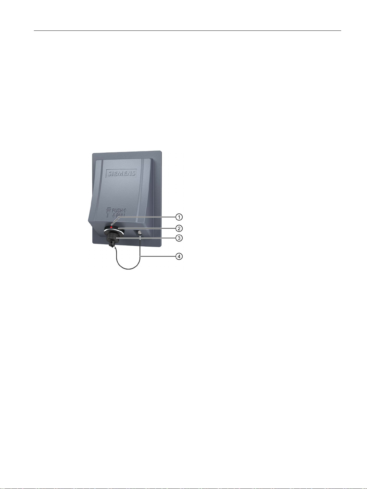
1.4
Connection boxes
Connection box compact
①
ing mark on the connection box when connecting.
②
Connection socket for the connecting cable
③
Cover cap
④
Safety strap
1.4 Connection boxes
The connection boxes are available in the following versions:
● Connection box compact, article number 6AV2125-2AE03-0AX0
● Connection box standard, article number 6AV2125-2AE13-0AX0
● Connection box advanced, article number 6AV2125-2AE23-0AX0
The figure below shows the connection box compact.
Positioning mark
There is also a red positioning mark on the connecting cable. Align this mark with the position-
TP1000F Mobile RO
Operating Instructions, 08/2017, A5E39831415-AA
15
Overview
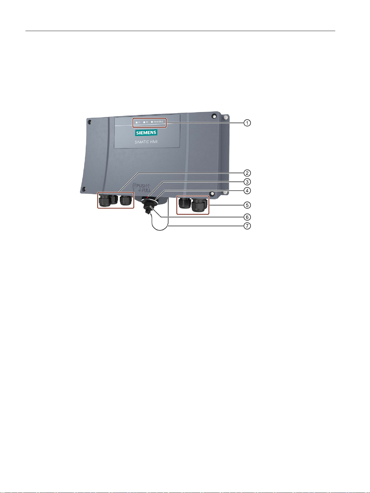
Connection box standard and connection box advanced
①
LED display
②
Screw glands for the data cables
③
ing mark on the connection box when connecting.
④
Connection socket for the connecting cable
⑤
Screw glands for power supply cables and F-signal
⑥
Cover cap
⑦
Safety strap
1.4 Connection boxes
The figure below shows the connection box standard or the connection box advanced. The
connection box advanced also features:
● Real-time Ethernet
● F-signal transmission
Positioning mark
There is also a red positioning mark on the connecting cable. Align this mark with the position-
There are three LEDs on the front of the connection box that indicate the status of
communication.
TP1000F Mobile RO
16 Operating Instructions, 08/2017, A5E39831415-AA

Overview
①
②
LED
See also
1.4 Connection boxes
LED display of the three Ethernet ports:
• P1: Fast Connector X1
• P2: Fast Connector X2
• P3: Connection socket for the Mobile Panel
Basic functions of the LEDs:
● LED lit green: Link established, no data transmission
● LED flashes green or amber: Link established, data transfer in progress
You can find information about other possible LED states in the following document:
Operating instructions "SCALANCE X-200"
(https://support.industry.siemens.com/cs/ww/en/view/102051962
)
Connecting the connection box (Page 50)
TP1000F Mobile RO
Operating Instructions, 08/2017, A5E39831415-AA
17

Overview
1.5
Scope of delivery
Mobile Panel 2nd Generation:
Connection box compact:
Connection box standard and connection box advanced:
Connecting cable:
Accessory kit
1.5 Scope of delivery
This section describes the system components in the scope of delivery that you need for
operating the HMI device.
● TP1000F Mobile RO
● 1 DVD with documentation and product information
● 1 "Mobile Panels 2nd Generation" Quick Install Guide
The scope of delivery may contain additional documents.
● 1 Connection box compact
● 1 DVD with documentation and product information
● 1 Accessory kit with mounting clips
● 1 Installation instruction
The scope of delivery may contain additional documents.
● 1 Connection box
● 1 DVD with documentation and product information
● 1 Installation instruction
The scope of delivery may contain additional documents.
● 1 Connecting cable with terminal compartment cover with four screws
● 1 Cable retainer with screw
The accessory kit of the HMI device includes the following:
● The "SIMATIC RemoteOperate - Application & Documentation" CD. The following
software and documents are included on the CD:
– The HMI device image with the operating system and the RemoteOperate Client
software
– These operating instructions and the RemoteOperate V4.0.0.1 programming manual
– The ProSave software for transferring the HMI device image to the HMI device
– The ProSave-Addon, which is required to select the TP1000F Mobile RO in ProSave
– The RemoteOperate Server software
– The "Readme.rtf" file in the main directory of the CD with additional information
● A touch pen for operating the touch screen.
Additional documents may be enclosed with the accessory kit.
TP1000F Mobile RO
18 Operating Instructions, 08/2017, A5E39831415-AA
Overview
1.6
Accessories
1.6.1
Overview
1.6.2
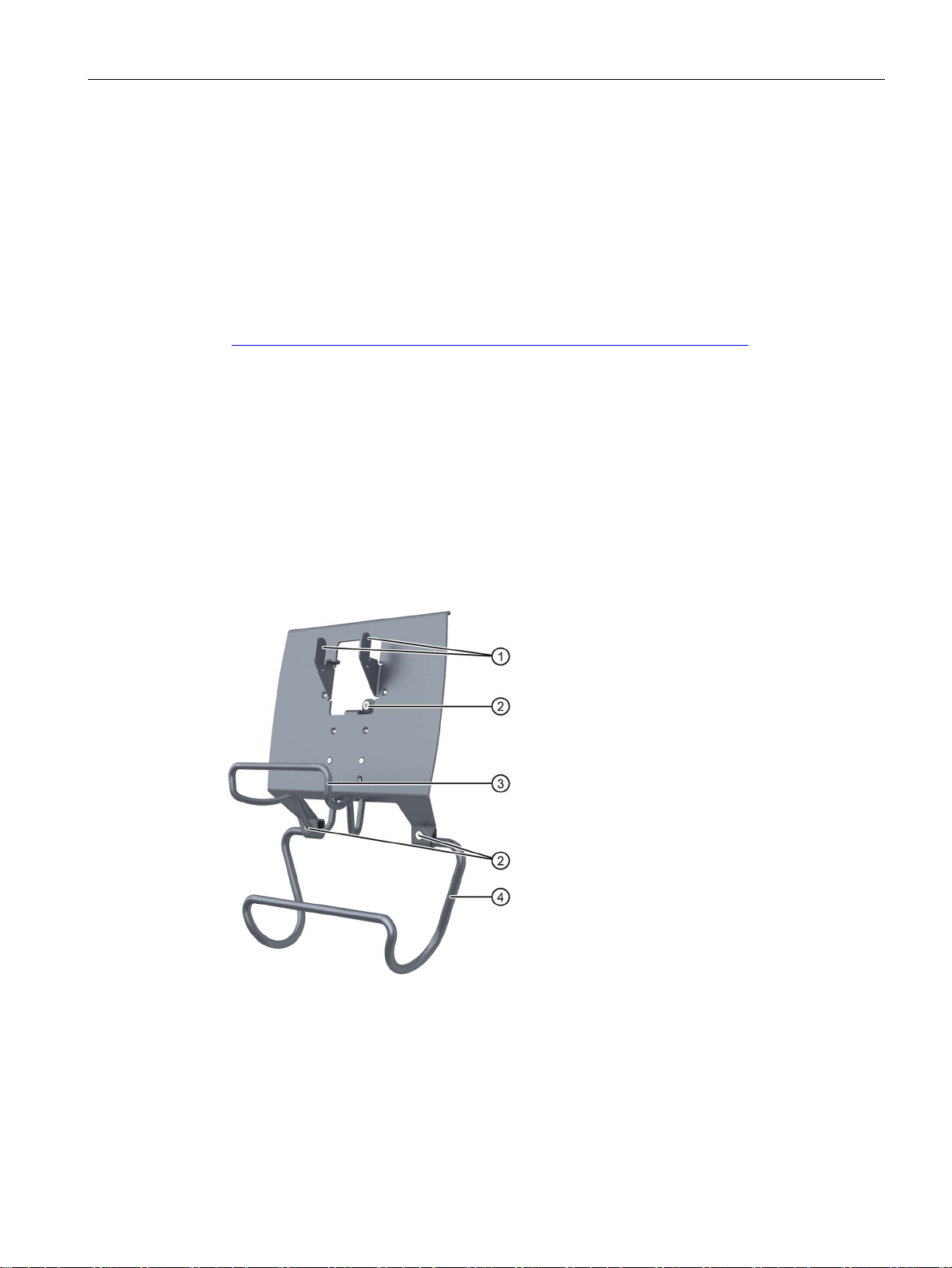
KTP Mobile wall-mounting bracket
①
Hooks for the handle on the Mobile Panel
②
Screw flange
③
Safety bar for the Mobile Panel
④
Holding bracket for the connecting cable
1.6 Accessories
Accessories are not included in the scope of delivery but can be ordered from the following
address:
SIMATIC HMI accessories
(https://mall.industry.siemens.com/mall/en/de/Catalog/Products/10030052
In the Industry Mall you can find the following accessories:
● KTP Mobile wall-mounting bracket
● Memory card
● Protective film for 4", 7", and 9" devices
)
The wall-mounting bracket holds the Mobile Panel securely in place during stationary
operation.
The assembly of the KTP Mobile wall-mounting bracket is described in the section
"Assembling the KTP Mobile wall-mounting bracket (Page 39)".
TP1000F Mobile RO
Operating Instructions, 08/2017, A5E39831415-AA
19

Overview
1.6.3
Touch pens
1.6.4
Storage media
1.6.5
SIRIUS safety relay
1.6 Accessories
The touch pens make it easier to operate the touch screen.
The touch pen set is not included with the HMI device. The touch pen set contains 5 pens
and is available under article number 6AV6645-7AB14-0AS0.
You can use the storage media to back up Mobile Panel data and copy data to the Mobile
Panel. Use the following storage media:
● SIMATIC HMI Memory Card
Siemens AG has approved the use of SD memory cards in the Mobile Panel.
● USB flash drive
The USB flash drive must be suitable for industrial applications. The storage medium is
inserted in the port on the left of the device.
If you are using a fail-safe Mobile Panel in a hardwired F system, you must use a safety
relay.
The Mobile Panels 2nd Generation have been tested with the following safety relays and
approved:
● SIRIUS safety relay, standard, relay output
article number 3SK1111-1AB30
● SIRIUS safety relay, standard, electronic output
article number 3SK1112-1BB40
● SIRIUS safety relay, advanced, relay output
article number 3SK1121-1AB40
● SIRIUS safety relay, advanced, electronic output
article number 3SK1122-1AB40
TP1000F Mobile RO
20 Operating Instructions, 08/2017, A5E39831415-AA

Overview
1.7
The HMI device in the operating process
The RemoteOperate software package
1.7 The HMI device in the operating process
The HMI device is part of the operating process. The operating process is marked by threeway communication between the HMI device, server and PLC. The following figure shows an
exemplary system design.
The HMI device is used for monitoring or controlling the operating process. The PLC in turn
supplies the server with the results of the operating process, which are displayed on the HMI
device.
Communication between the HMI device and the server is handled using the
RemoteOperate software package.
Using RemoteOperate you can monitor or operate a server from a client. The range of
operations covers all the functions of the server.
The RemoteOperate software package comprises two components:
● The RemoteOperate Server software
● The RemoteOperate Client software
A detailed description of the RemoteOperate software can be found in the "RemoteOperate
V4.0.0.1" programming manual.
TP1000F Mobile RO
Operating Instructions, 08/2017, A5E39831415-AA
21

Overview
1.8
Terms for fail-safe operation
Fail-safe automation system, F system
hard-wired F-system
Safe operating state
Fail-safe operation
1.8 Terms for fail-safe operation
This section defines terms relating to fail-safe operation with a fail-safe HMI device.
You can find additional information on the topic of "Safety" in the following document:
"SIMATIC Safety - Configuring and Programming" programming and operating manual
(http://support.automation.siemens.com/WW/view/en/54110126
)
A fail-safe automation system is required in a plant with high safety requirements. An Fsystem is characterized by the following features:
● Safety-related shutdown response of the system after the triggering of a stop or
emergency stop via a safety-related operator control.
● The confirmation of machine movements entailing danger via an enabling mechanism.
In combination with the fail-safe Mobile Panel, a
related operator controls are wired to a safety relay. If one of the safety-related operator
controls is activated, the safety relay triggers the safe state or confirms a machine movement
entailing danger in the F-system via the enabing button.
If an unexpected event occurs during plant operation that poses a risk to persons or
equipment, the plant must respond with a defined safety shutdown. Protection of personnel
against physical injury can only be ensured if intervention in manufacturing processes, for
example during retrofitting or troubleshooting, is safe and secure.
Based on the risk analysis, the safety shutdown and therefore the shutdown response of the
plant must therefore be configured to ensure that the plant or plant area can be switched to a
safe operating state in the event of a risk.
In addition to the qualitative risk analysis required, the machine operator also has an
obligation to make a quantitative assessment of potential hazards. On this basis, the
operator must then establish what risks could arise during plant or plant area operation and
whether the relevant safety functions are sufficiently effective for the hazard in question.
The safe operating state is assigned to the fail-safe controller by a safety program. The plant
constructor is responsible for the required configuration which should be described in the
plant documentation.
is used: The safety-
In a hardwired F-system, you operate the plant or a plant section in fail-safe mode. In failsafe mode, the safety-related operator controls emergency stop/stop button and enabling
buttons are active. Fail-safe mode runs via a fixed connection with a safety relay.
TP1000F Mobile RO
22 Operating Instructions, 08/2017, A5E39831415-AA

Overview
Emergency stop, stop
Safety-related operating mode
stop button
emergency stop
button
Emergency stop / stop bypass
1.9 Organizational measures
The operator presses the emergency stop / stop button to activate either an emergency stop
or a stop.
● The emergency stop is an emergency action that is intended to stop a process or
movement entailing danger. All machines that are assigned to the trigger are immediately
brought to a safe state via the emergency stop.
● The emergency stop / stop button of the HMI device brings about a safety-related stop of
the plant or machine in accordance with EN 60204-1, Section 9.2.5.3.
Whether the emergency stop / stop button causes an "emergency stop" or "stop" function
must be decided upon and configured on the basis of the risk analysis.
In fail-safe mode, you can use the HMI device in combination with a connection box in one of
the following operating modes:
● Stop button evaluated by safety relay
The signals of the safety-related operator controls are wired to a safety relay. If you press
the emergency stop / stop button, the plant typically responds with a stop.
The emergency stop / stop button does not light up.
In this operating mode, the emergency stop / stop button is called the
● E-stop button evaluated by safety relay
The signals of the safety-related operator controls are wired to a safety relay. When you
press the emergency stop / stop button, the plant responds with an emergency stop.
The emergency stop / stop button lights up when active.
In this operating mode, the emergency stop / stop button is called the
.
The emergency stop / stop bypass is a function of the connection box advanced for
hardwired F-systems.
The function ensures that no stop or emergency stop will be triggered in the plant when
reconnecting the Mobile Panel to another connection box.
.
TP1000F Mobile RO
Operating Instructions, 08/2017, A5E39831415-AA
23

Overview
1.9
Organizational measures
Measures
F-systems
Connection box
Hardwired F-system, no emergency
stop/stop bypass
Hardwired F-system with emergency
stop/stop bypass
compact
Yes
No
advanced
No
Yes
Stop button evaluated by safety relay
Stop button evaluated by safety relay
E-stop button evaluated by safety relay
E-stop button evaluated by safety relay
1.10
Mobile Panel and connection box compatibility
Compatibility of Mobile Panels 2nd Generation – connection box PN Basic and PN Plus
1.9 Organizational measures
If you are using a fail-safe Mobile Panel in a fail-safe system, you must consider the
following organizational measures:
● Install stationary emergency stop or emergency off buttons in the plant that are effective
independent of the Mobile Panel.
● Perform a risk analysis of the plant.
● If the overall plant is not to be monitored from a single location, configure plant areas.
● Select the same operating mode for all connection boxes in a contiguous plant area.
● Create a safety program.
● Run an acceptance test on the fail-safe automation system.
The table below shows the F-systems that can be configured or installed for a given
connection box. Requirement is that you are using a fail-safe Mobile Panel.
standard Yes No
Safety-related
operating mode
The Mobile Panels 2nd Generation are not compatible with the connection box DP Basic and
connection box DP Plus.
The TP1000F Mobile RO is compatible with the following connection boxes:
● Connection box PN Basic, article number 6AV6671-5AE01-0AX0
● Connection box PN Plus, article number 6AV6671-5AE11-0AX0
Restrictions:
● Only one hardwired F-system with a stop function and enabling function is permitted.
TP1000F Mobile RO
24 Operating Instructions, 08/2017, A5E39831415-AA
2
2.1
General safety instructions
WARNING
Personal injury or material damage due to non-compliance with safety regulations
Safety during configuration and operational safety of the plant
WARNING
Personal injury or material damage due to improper configuration of the plant
WARNING
Programming startup protection in the safety program
Failure to exactly comply with the safety regulations and procedures in this document can
result in hazards and disable safety functions. This can result in personal injuries or
material damage.
Closely follow closely the safety regulations and procedural instructions in each situation.
Observe the safety and accident prevention regulations applicable to your application in
addition to the safety instructions given in this document.
The configuration engineer for plant control must take precautions to ensure that an
interrupted program will be correctly integrated again after communication failures, voltage
dips or power outages.
A dangerous operating state must not be allowed to occur - not even temporarily - during
the entire execution of the control program, even during a troubleshooting.
At a STOP/RUN transition of an F-CPU, the standard user program starts up as usual.
When the safety program starts up, all FDBs are initialized with values from the load
memory, same as during a cold restart. As a result, saved error information is lost. The Fsystem performs an automatic reintegration of the F-I/O. A startup of the safety program
with values from the load memory can also be initiated by a handling error or an internal
error. If the process does not permit this, a (re)start protection must be programmed in the
safety program. The output of process values must be disabled until manually enabled; this
must not occur until the process values can be output without posing a hazard and errors
have been eliminated.
TP1000F Mobile RO
Operating Instructions, 08/2017, A5E39831415-AA
25
Safety instructions
NOTICE
Exclusive operating right
Configuration of fail-safe Mobile Panels
WARNING
Personal injury or property damage in case of remote control of a fail-safe HMI device
WARNING
Personal injury or material damage with different operating modes in a plant area
Operational safety in the plant
WARNING
Short-term PROFINET IO interruptions possible when using protocols with alternative
communication paths
2.1 General safety instructions
Operating the plant with multiple HMI devices simultaneously can cause material damage.
Prevent simultaneous operation of the plant from multiple devices by configuring the
assignment of operating rights to only one HMI device.
The remote control of a fail-safe unit consisting of HMI devices with RemoteOperate Client
and a RemoteOperate server is not permitted because it is not ensured that the hazardous
location is visible during operation. This can result in personal injury or property damage.
The following therefore applies to the fail-safe unit (RemoteOperate Clients /
RemoteOperate Server): Remote control, for example, by means of Telnet or Sm@rtClient
is not permitted.
If you assign different operating modes to the connection boxes in a contiguous plant area,
the emergency stop / stop button may light at one of the connection boxes but not at
another. When the emergency stop / stop button does not light up, it is not apparent to the
operator if the safety-related operator controls are active or not. This can result in personal
injury or material damage due to maloperation.
Only configure a single operating mode for multiple connection boxes in a contiguous plant
area.
The following applies when you use a protocol with alternative communication paths, for
example, MRP, STP or RSTP, for PROFINET communication: When an interruption in the
network occurs, for example, due to a cable break, PROFINET IO interruptions can occur
during the switching time to the alternative communication path. This can result in personal
injury or material damage.
Take appropriate protection measures to prevent physical injury or material damage.
You can find additional information in the following document:Configuration manual
"SCALANCE X-200" (https://support.industry.siemens.com/cs/ww/de/view/109476763
)
TP1000F Mobile RO
26 Operating Instructions, 08/2017, A5E39831415-AA
Safety instructions
Note
Observe the Operational Safety and Product Monitoring newsletter.
Plants with safety
safety on the part of t
measures for monitoring the product. We therefore provide a special newsletter about
product development and properties to inform you about important safety aspects for the
operation of plants.
make changes to your plant, you should subscribe to the appropriate newsletter.
Subscribe to the newsletter for fail
software at the foll
(
To receive these newsletters, select the "News" check box.
Safety during commissioning
WARNING
Potential personal injury or material damage due to non-compliance with machine
regulations
Safety when working in and on electrical systems
Note
These safety steps must always be taken in the above order before any work on electrical
systems. Once work on an electrical system is finished, cancel the safety steps starting with
the last and finishing with
2.1 General safety instructions
-related characteristics are subject to special requirements for operational
he operator. Vendors are also required to comply with certain
To ensure that you are always kept up-to-date in this regard and can
-safe system components and the SIMATIC industrial
owing link: Newsletter
https://www.industry.siemens.com/newsletter/public/AllNewsletters.aspx)
If it is unclear whether or not the machine operated with the HMI device described in this
document meets the provisions of Directive 2006/42/EC, the machine must not be put into
operation as there is a risk of personal injury and/or material damage.
Verify before commissioning that the provisions of Directive 2006/42/EC are fulfilled.
Work in or on electrical systems may only be carried out by authorized persons. The
following safety regulations apply for the prevention of electric shock and electrocution:
1. Switch off the system
2. Secure the system to prevent it switching back on
3. Check the system to ensure it is de-energized
4. Ground and short the system
5. Cover or shield adjacent live parts
TP1000F Mobile RO
Operating Instructions, 08/2017, A5E39831415-AA
Label the electrical system in accordance with the applicable safety provisions when work is
to be carried out.
the first.
27
Safety instructions
Strong high-frequency radiation
NOTICE
Observe immunity to RF radiation
ESD
Safety during operation
WARNING
Danger of injury
WARNING
HMI device failure
Note
The emergency stop / stop button can be triggered unintentionally when the HMI device is
dropped. This can result in an uninte
2.1 General safety instructions
Always adhere to the safety provisions applicable in the country of use.
The device has an increased immunity to RF radiation according to the specifications on
electromagnetic compatibility in the technical specifications.
Radiation exposure in excees of the specified immunity limits can impair device functions,
result in malfunctions and therefore injuries or damages.
Read the information on immunity to RF radiation in the technical specifications.
A device with electronic components is an electrostatic sensitive device. Due to their design,
electronic components are sensitive to overvoltage and thus to the discharge of static
electricity. Note the applicable regulations for ESD.
If the HMI device is to be used for manual movements in setup mode and the enabling
button is not active, there is a serious risk for the operating personnel.
For a project used to set up a plant, make sure that each movement requires the operation
of the enabling button. Only allow movements with the enabling button and at a reduced
speed.
A strong shock or impact can impair the proper functioning of the Mobile Panel.
After any mechanical shock or impact, check that the Mobile Panel and the safety-related
parts are in working order.
nded shutdown of the plant.
TP1000F Mobile RO
28 Operating Instructions, 08/2017, A5E39831415-AA

Safety instructions
Note
The function of the emergency stop / stop button must be checked regularly. See "
Mobile Panel readiness for operation
Industrial Security
Disclaimer for third-party software updates
Notes on protecting administrator accounts
2.1 General safety instructions
Testing
(Page 70)".
Siemens provides products and solutions with industrial security functions that support the
secure operation of plants, systems, machines and networks.
In order to protect plants, systems, machines and networks against cyber threats, it is
necessary to implement – and continuously maintain – a holistic, state-of-the-art industrial
security concept. Siemens’ products and solutions only form one element of such a concept.
Customer is responsible to prevent unauthorized access to its plants, systems, machines
and networks. Systems, machines and components should only be connected to the
enterprise network or the internet if and to the extent necessary and with appropriate security
measures (e.g. use of firewalls and network segmentation) in place.
Additionally, Siemens’ guidance on appropriate security measures should be taken into
account. For more information about industrial security, please visit
(http://www.siemens.com/industrialsecurity
).
Siemens’ products and solutions undergo continuous development to make them more
secure. Siemens strongly recommends to apply product updates as soon as available and to
always use the latest product versions. Use of product versions that are no longer supported,
and failure to apply latest updates may increase customer’s exposure to cyber threats.
To stay informed about product updates, subscribe to the Siemens Industrial Security RSS
Feed under (http://www.siemens.com/industrialsecurity
This product includes third-party software. Siemens AG only provides a warranty for
updates/patches of the third-party software, if these have been distributed as part of a
Siemens software update service contract or officially released by Siemens AG. Otherwise,
updates/patches are undertaken at your own risk. You can find more information about our
Software Update Service offer on the Internet at Software Update Service
http://www.automation.siemens.com/mcms/automation-software/en/software-update-
(
service).
A user with administrator privileges has extensive access and manipulation options in the
system.
Therefore, ensure there are adequate safeguards for protecting the administrator accounts
to prevent unauthorized changes. To do this, use secure passwords and a standard user
account for normal operation. Other measures, such as the use of security policies, should
be applied as needed.
).
TP1000F Mobile RO
Operating Instructions, 08/2017, A5E39831415-AA
29

Safety instructions
2.2
Notes about usage
NOTICE
HMI device approved for indoor use only
Note
Using an Ethernet data transmission rate of 100 Mbps
The Ethernet data transmission rate of 10
Generation.
Use a data transmission rate of 100
Industrial applications
Use in residential areas
Note
The HMI device is not intended for use in residential areas. The operation of HMI devices in
r
2.2 Notes about usage
The HMI device may be damaged if operated outdoors.
Operate the HMI device indoors only.
Mbps is not supported by Mobile Panels 2nd
Mbps for communication with the device.
The HMI device is designed for industrial applications. It conforms to the following standards:
● Requirements for emitted interference EN 61000-6-4 +A1
● Requirements for interference immunity EN 61000-6-2
esidential areas can cause interference to radio and television reception.
If the HMI device is used in a residential area, you must take measures to achieve Limit
Class B conforming to EN 55011 for RF interference.
A suitable measure for achieving the RF interference level to Limit Class B, for example, is
the use of filters in power supply lines.
Individual acceptance is required for these measures.
TP1000F Mobile RO
30 Operating Instructions, 08/2017, A5E39831415-AA
 Loading...