

Siemens SIMATIC HMI OP3 Equipment Manual

RGB ELEKTRONIKA AGACIAK CIACIEK
SPÓŁKA JAWNA
Jana Dlugosza 2-6 Street
51-162 Wrocław
Poland
biuro@rgbelektronika.pl
+48 71 325 15 05
www.rgbautomatyka.pl
www.rgbelektronika.pl
DATASHEET
www.rgbautomatyka.pl
www.rgbelektronika.pl
OTHER SYMBOLS:
KEYPAD 6AV3503-1DB10
KEYPAD6AV35031DB10, KEYPAD6AV3503 1DB10, KEYPAD6AV3503-1DB10, KEYPAD 6AV35031DB10, KEYPAD
6AV3503 1DB10, KEYPAD 6AV3503-1DB10
SIEMENS

YOUR
PARTNER IN
MAINTENANCE
At our premises in Wrocław, we have a fully equipped servicing facility. Here we perform all the repair
works and test each later sold unit. Our trained employees, equipped with a wide variety of tools and
having several testing stands at their disposal, are a guarantee of the highest quality service.
OUR SERVICES
ENCODERS
SERVO
DRIVERS
LINEAR
ENCODERS
SERVO AMPLIFIERS
CNC
MACHINES
MOTORS
POWER
SUPPLIERS
OPERATOR
PANELS
CNC
CONTROLS
INDUSTRIAL
COMPUTERS
PLC
SYSTEMS
Repair this product with RGB ELEKTRONIKA
ORDER A DIAGNOSIS
∠
Buy this product at RGB AUTOMATYKA
BUY
∠
Preface, Contents
Part I Introduction
1
2
Part II Functions of the OP3
3
12
Part III Installation and
Commissioning
13
14
Part IV Device Description,
Test and
Monitoring Functions
15
16
Part V Appendices
A
E
Glossary, Index
Release 11/99
OP3
Operator Panel
Equipment Manual
SIMATIC HMI
6AV3591–1AD00–1AB0
This manual contains notices which you should observe to ensure your own personal safety, as
well as to protect the product and connected equipment. These notices are highlighted in the
manual by a warning triangle and are marked as follows according to the level of danger:
!
Warning
indicates that death, severe personal injury or substantial property damage can result if proper
precautions are not taken.
!
Caution
indicates that minor personal injury or property damage can result if proper precautions are not
taken.
Note
draws your attention to particularly important information on the product, handling the product,
or to a particular part of the documentation.
Equipment may be commissioned and operated only by qualified personnel. Qualified person-
nel within the meaning of the safety notices in this manual are persons who are authorized to
commission, ground and identify equipment, systems and circuits in accordance with safety
engineering standards.
Note the following:
!
Warning
The equipment may be used only for the applications stipulated in the catalog and in the tech-
nical description and only in conjunction with other equipment and components recommended
or approved by Siemens.
Startup must not take place until it is established that the machine, which is to accommodate
this component, is in conformity with the guideline 89/392/EEC.
Faultless and safe operation of the product presupposes proper transportation, proper storage,
erection and installation as well as careful operation and maintenance.
The approvals that apply to the device are detailed in the Chapter Technical Data.
The registered trademarks of Siemens AG are listed in the Preface. Some of the other
designations used in these documents are also registered trademarks; the owner’s rights may be
violated if they are used be third parties for their own purposes.
Editor and Publisher: A&D PT1
We have checked the contents of this manual for agreement with
the hardware and software described. Since deviations cannot be
precluded entirely , we cannot guarantee full agreement. However ,
the data in this manual are reviewed regularly and any necessary
corrections included in subsequent editions. Suggestions for im-
provement are welcomed.
Technical data subject to change.
Siemens AG 1999
Disclaimer of LiabilityCopyright Siemens AG 1999 All rights reserved
The reproduction, transmission or use of this document or its
contents is not permitted without express written authority.
Offenders will be liable for damages. All rights, including rights
created by patent grant or registration of a utility model or design,
are reserved.
Siemens AG,
Automation & Drives
SIMATIC Human Machine Interface
A&D PT1 D1
Postfach 4848, D-90327 Nuernberg
Siemens Aktiengesellschaft Order No. 6AV3591–1AD00–1AB0
Safety Guidelines
Qualified Personnel
Correct Usage
Approvals
Trademarks
Impressum

i
Operator Panel OP3
Edition 11/99
Preface
This equipment manual provides operators, fitters, configurers and system
support engineers with information about the functionality and technical
design of the OP3.
The equipment manual Operator Panel OP3 is organized into five parts:
Part Chapters Contents
I 1 - 2 Overview of the Operator Panel and range of
functions in tabular form.
II 3 - 4
5 - 11
12
How to operate the OP3.
Step-by-step instructions on how to operate the
Operator Panel using the standard screens.
Information on how to connect the OP3 to the
SIMATIC S7.
III 13 - 14 – Mechanical and electrical installation,
– Commissioning
IV 15 - 16 – Dimensions and connection elements,
– Test and monitoring functions
V Appendix – Brief descriptions of standard screens,
– System messages,
– Technical data,
– ESD guidelines,
– SIMATIC HMI documentation,
– Glossary of technical terms.
Purpose
Organization of
the manual
ii
Operator Panel OP3
Edition 11/99
The following conventions are used in this manual:
Motor off Text on the display of the OP3 is shown in ”type-
writer” style.
Variable Symbolic names representing variable values on the
display of the OP3 are shown in italic ”typewriter”
style.
System Functions which you can choose are shown in nor-
mal italics.
System → Mode Steps that are performed in succession are linked by
an arrow.
ESC The names of keys are shown in a different type.
The various releases of the equipment manual correspond to the following
firmware and ProTool versions:
Release Remarks ProTool version
07/95 First release of the OP3 equipment
manual
V 2.0 and later
08/96 Technical content of the equipment ma-
nual reviewed
V 3.0 and later
11/99 Technical content of the equipment
manual reviewed
V 5.1 and later
The following names are registered trademarks of the Siemens AG:
• SIMATIC
• SIMATIC HMI
• HMI
• ProTool
• ProTool/Lite
• ProTool/Pro
• SIMATIC Multi Panel
• SIMATIC Multifunctional Platform
• MP 270
• ProAgent
Conventions
History
Trademarks
Preface

iii
Operator Panel OP3
Edition 11/99
In the case of technical queries, please contact your local Siemens in the sub-
sidiaries and branches responsible for your area.
Available worldwide, at all times:
Johnson City
Nuernberg
Singapur
Simatic Basic Hotline
Nuernberg
SIMA TIC BASIC Hotline
Johnson City
SIMA TIC BASIC Hotline
Singapur
SIMA TIC BASIC Hotline
Local time: Mo - Fr 7:00 to 17:00
T elephone: +49 (911) 895-7000
Fax: +49 (911) 895-7002
E-Mail: simatic.support@
nbgm.siemens.de
Local time: Mo - Fr 8:00 to 19:00
T elephone: +1 423 461-2522
Fax: +1 423 461-2231
E-Mail: simatic.hotline@
sea.siemens.com
Local time: Mo - Fr 8:30 to 17:30
T elephone: +65 740-7000
Fax: +65 740-7001
E-Mail: simatic.hotline@
sae.siemens.com.
SIMA TIC Premium Hotline
(charged, only with SIMATIC Card)
Time: Mo - Fr 0:00 to 24:00
T elephone: +49 (911) 895-7777
Fax: +49 (911) 895-7001
Other support
SIMATIC Customer
Support Hotline
Preface
iv
Operator Panel OP3
Edition 11/99
SIMATIC Customer Support offers comprehensive additional information
concerning SIMATIC products through its Online services as follows:
• Up–to–date general information is provided
– in Internet under http://www.ad.siemens.de/simatic
– via Fax-Polling under 08765-93 02 77 95 00
• Up–to–date product information and downloads for practical use can be
found:
– in Internet unter http://www.ad.siemens.de/support/
html–00/
– via the Bulletin Board System (BBS) in Nürnberg (SIMATIC Custo-
mer Support Mailbox) under +49
(911) 895–7100
In order to contact the mailbox, please use a modem with up to 28.8
kBaud (V.34) capacity. Set the parameters as follows: 8, N, 1, ANSI,
or dial for connection via ISDN (x.75, 64 kBit).
The abbreviations used in this equipment manual have the following
meaning:
EPROM (with UV light) erasable programmable read-only memory
RAM Random access memory (working memory)
AM Alarm Message
CPU Central Processing Unit
EM Event message
ESD Electrostatic Sensitive Device
LCD Liquid Crystal Display
LED Light–Emitting Diode
MPI Multipoint Interface (SIMATIC S7)
PC Personal Computer
PLC Programmable Logic Controller
PU Programming Unit
PPI Point to Point Interface (SIMATIC S7)
SRAM Static Random Access Memory
OP Operator Panel
SIMATIC Customer
Online Services
Abbreviations
Preface
i
Operator Panel OP3
Edition 11/99
Contents
Part I INTRODUCTION
1 Product Description 1-1. . . . . . . . . . . . . . . . . . . . . . . . . . . . . . . . . . . . . . . . . . . .
1.1 Configuration and Process Control Phases 1-1. . . . . . . . . . . . . . . . .
1.2 Configuration of OP3 1-3. . . . . . . . . . . . . . . . . . . . . . . . . . . . . . . . . . . .
2 Functionality 2-1. . . . . . . . . . . . . . . . . . . . . . . . . . . . . . . . . . . . . . . . . . . . . . . . . . .
Part II FUNCTIONS OF THE OP3
3 General Operation 3-1. . . . . . . . . . . . . . . . . . . . . . . . . . . . . . . . . . . . . . . . . . . . . .
3.1 Keyboard 3-1. . . . . . . . . . . . . . . . . . . . . . . . . . . . . . . . . . . . . . . . . . . . . .
3.1.1 SHIFT for Digits and Soft Keys 3-3. . . . . . . . . . . . . . . . . . . . . . . . . . .
3.2 Entering Values 3-4. . . . . . . . . . . . . . . . . . . . . . . . . . . . . . . . . . . . . . . . .
3.2.1 Entering Numerical Values 3-5. . . . . . . . . . . . . . . . . . . . . . . . . . . . . . . .
3.2.2 Entering Alphanumeric Values 3-6. . . . . . . . . . . . . . . . . . . . . . . . . . . .
3.2.3 Entering Symbolic Values 3-6. . . . . . . . . . . . . . . . . . . . . . . . . . . . . . . .
4 Using the OP3 with Its Standard Functions 4-1. . . . . . . . . . . . . . . . . . . . . . .
4.1 Operating Levels 4-1. . . . . . . . . . . . . . . . . . . . . . . . . . . . . . . . . . . . . . . .
4.2 Standard Screens 4-3. . . . . . . . . . . . . . . . . . . . . . . . . . . . . . . . . . . . . . .
4.3 Branching in Standard Screens 4-5. . . . . . . . . . . . . . . . . . . . . . . . . . .
5 Screens 5-1. . . . . . . . . . . . . . . . . . . . . . . . . . . . . . . . . . . . . . . . . . . . . . . . . . . . . . . .
5.1 Screen Entries 5-2. . . . . . . . . . . . . . . . . . . . . . . . . . . . . . . . . . . . . . . . . .
5.2 Choosing Screens 5-3. . . . . . . . . . . . . . . . . . . . . . . . . . . . . . . . . . . . . . .
5.3 Editing Screens 5-3. . . . . . . . . . . . . . . . . . . . . . . . . . . . . . . . . . . . . . . . .
6 Password Protection 6-1. . . . . . . . . . . . . . . . . . . . . . . . . . . . . . . . . . . . . . . . . . .
6.1 Password Levels and Access 6-1. . . . . . . . . . . . . . . . . . . . . . . . . . . . .
6.2 Logging In and Out on the OP3 6-2. . . . . . . . . . . . . . . . . . . . . . . . . . .
6.3 Password Management 6-2. . . . . . . . . . . . . . . . . . . . . . . . . . . . . . . . . .
7 Messages 7-1. . . . . . . . . . . . . . . . . . . . . . . . . . . . . . . . . . . . . . . . . . . . . . . . . . . . . .
7.1 Event Messages 7-1. . . . . . . . . . . . . . . . . . . . . . . . . . . . . . . . . . . . . . . .
7.2 System Messages 7-3. . . . . . . . . . . . . . . . . . . . . . . . . . . . . . . . . . . . . . .
ii
Operator Panel OP3
Edition 11/99
7.3 Displaying Messages 7-4. . . . . . . . . . . . . . . . . . . . . . . . . . . . . . . . . . . .
8 Timers and Counters 8-1. . . . . . . . . . . . . . . . . . . . . . . . . . . . . . . . . . . . . . . . . . .
8.1 Counters 8-1. . . . . . . . . . . . . . . . . . . . . . . . . . . . . . . . . . . . . . . . . . . . . . .
8.2 Timers 8-2. . . . . . . . . . . . . . . . . . . . . . . . . . . . . . . . . . . . . . . . . . . . . . . . .
9 STATUS VAR and FORCE VAR with the OP3 9-1. . . . . . . . . . . . . . . . . . . . . .
10 System Settings on Standard Screens 10-1. . . . . . . . . . . . . . . . . . . . . . . . . . .
10.1 Selecting a Language 10-1. . . . . . . . . . . . . . . . . . . . . . . . . . . . . . . . . . . .
10.2 Setting Date and Time 10-2. . . . . . . . . . . . . . . . . . . . . . . . . . . . . . . . . . .
10.3 Setting Modes 10-2. . . . . . . . . . . . . . . . . . . . . . . . . . . . . . . . . . . . . . . . . .
10.4 Modifying the Address in MPI Network Configuration 10-3. . . . . . . . .
11 Process-Dependent Operator Guidance 11-1. . . . . . . . . . . . . . . . . . . . . . . . . .
11.1 Branching by Means of Soft Keys 11-1. . . . . . . . . . . . . . . . . . . . . . . . .
11.2 Self-Defined Screen Hierarchy 11-2. . . . . . . . . . . . . . . . . . . . . . . . . . . .
11.3 Evaluating Screen Numbers 11-4. . . . . . . . . . . . . . . . . . . . . . . . . . . . . .
11.4 System Keyboard Assignment 11-6. . . . . . . . . . . . . . . . . . . . . . . . . . . .
12 Communication 12-1. . . . . . . . . . . . . . . . . . . . . . . . . . . . . . . . . . . . . . . . . . . . . . . .
12.1 Connecting to an S7-200 via the PPI 12-2. . . . . . . . . . . . . . . . . . . . . . .
12.2 Connecting to an S7-300 via the MPI 12-3. . . . . . . . . . . . . . . . . . . . . .
12.3 Interface Area for the SIMATIC S7 12-5. . . . . . . . . . . . . . . . . . . . . . . . .
12.3.1 Control and Response Bits 12-6. . . . . . . . . . . . . . . . . . . . . . . . . . . . . . .
12.3.2 Connection ID 12-6. . . . . . . . . . . . . . . . . . . . . . . . . . . . . . . . . . . . . . . . . .
12.3.3 Time and Date 12-7. . . . . . . . . . . . . . . . . . . . . . . . . . . . . . . . . . . . . . . . . .
Part III INSTALLATION AND COMMISSIONING
13 Installation 13-1. . . . . . . . . . . . . . . . . . . . . . . . . . . . . . . . . . . . . . . . . . . . . . . . . . . . .
13.1 Mechanical Installation 13-2. . . . . . . . . . . . . . . . . . . . . . . . . . . . . . . . . . .
13.2 Electrical Installation 13-3. . . . . . . . . . . . . . . . . . . . . . . . . . . . . . . . . . . . .
13.3 Connecting the Configuration Computer 13-4. . . . . . . . . . . . . . . . . . . .
13.4 Connection to the PLC 13-5. . . . . . . . . . . . . . . . . . . . . . . . . . . . . . . . . . .
14 Commissioning 14-1. . . . . . . . . . . . . . . . . . . . . . . . . . . . . . . . . . . . . . . . . . . . . . . .
Part IV DEVICE DESCRIPTION, TEST AND MONITORING FUNCTIONS
15 Device Description 15-1. . . . . . . . . . . . . . . . . . . . . . . . . . . . . . . . . . . . . . . . . . . . .
15.1 Dimension Drawings 15-1. . . . . . . . . . . . . . . . . . . . . . . . . . . . . . . . . . . . .
15.2 Connection Elements 15-2. . . . . . . . . . . . . . . . . . . . . . . . . . . . . . . . . . . .
Contents

iii
Operator Panel OP3
Edition 11/99
15.3 Contrast Control 15-4. . . . . . . . . . . . . . . . . . . . . . . . . . . . . . . . . . . . . . . .
16 Test and Monitoring Functions 16-1. . . . . . . . . . . . . . . . . . . . . . . . . . . . . . . . . .
Part V APPENDICES
A Brief Description of Standard Screens A-1. . . . . . . . . . . . . . . . . . . . . . . . . . .
B System Messages B-1. . . . . . . . . . . . . . . . . . . . . . . . . . . . . . . . . . . . . . . . . . . . . .
C Technical Data C-1. . . . . . . . . . . . . . . . . . . . . . . . . . . . . . . . . . . . . . . . . . . . . . . . .
D ESD Guidelines D-1. . . . . . . . . . . . . . . . . . . . . . . . . . . . . . . . . . . . . . . . . . . . . . . .
D.1 What Does ESD Mean? D-1. . . . . . . . . . . . . . . . . . . . . . . . . . . . . . . . . .
D.2 Important Precautions against Charge D-2. . . . . . . . . . . . . . . . . . . . .
D.3 Handling ESDs D-2. . . . . . . . . . . . . . . . . . . . . . . . . . . . . . . . . . . . . . . . . .
D.4 Measuring and Modifying ESDs D-2. . . . . . . . . . . . . . . . . . . . . . . . . . .
D.5 Shipping ESDs D-3. . . . . . . . . . . . . . . . . . . . . . . . . . . . . . . . . . . . . . . . . .
E SIMATIC HMI Documentation E-1. . . . . . . . . . . . . . . . . . . . . . . . . . . . . . . . . . . .
Glossary Glossary-1. . . . . . . . . . . . . . . . . . . . . . . . . . . . . . . . . . . . . . . . . . . . . . . . . . . . . . .
Index Index-1. . . . . . . . . . . . . . . . . . . . . . . . . . . . . . . . . . . . . . . . . . . . . . . . . . . . . . . . . .
Contents

iv
Operator Panel OP3
Edition 11/99
Contents

INTRODUCTION
1 Product Description
2 Functionality
Part I

2-2
Operator Panel OP3
Edition 11/99
1-1
Operator Panel OP3
Edition 11/99
Product Description
The device SIMATIC HMI OP3 allows operating states and current process
values of a connected SIMATIC S7 PLC to be visualized. In addition, inputs
can be made on the OP3 and written to the PLC. Functions relating to
machine diagnostics can also be executed on the OP3.
The OP3 is suitable for fitting into switching cabinets and control desks, and
for use as a hand-held device.
1.1 Configuration and Process Control Phases
Before the OP3 can go into service, it has to be prepared for its job of
visualizing data from the PLC, i.e. it has to be configured. To do so, data
areas used by the OP3 to communicate with the PLC have to be created in
the memory of the PLC.
The configuration for the OP3 is created on a configuration computer
(PC/PU) using the ProTool configuration software. When the configuration is
ready, it is transferred to the OP3. During operation, the OP3 communicates
with the PLC to which it is connected and reacts to program execution on the
PLC according to the configured requirements.
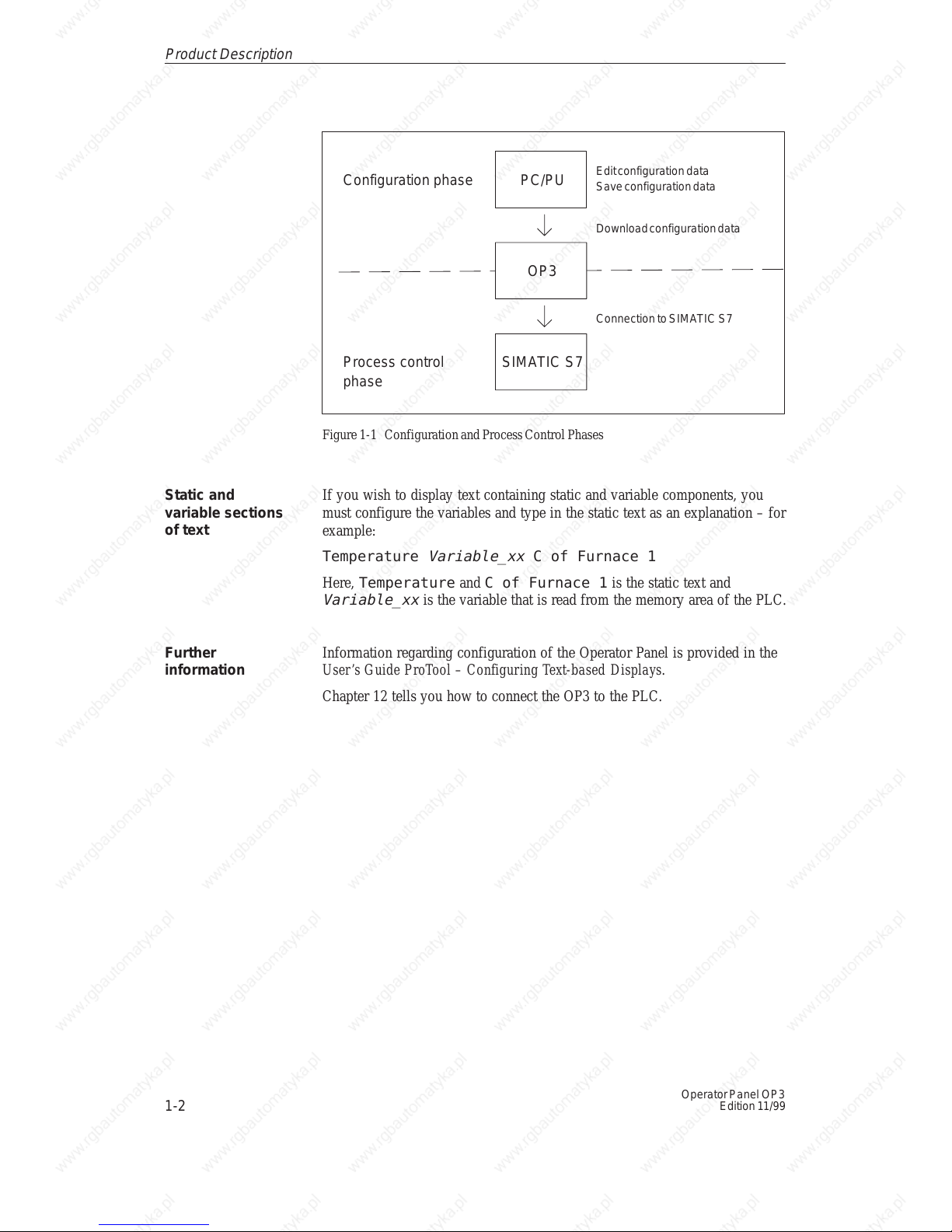
The following illustration depicts the configuration and process control
phases:
Using the OP3
Creating data
areas
Configuring with
ProTool
1
1-2
Operator Panel OP3
Edition 11/99
PC/PU
OP3
SIMATIC S7
Edit configuration data
Save configuration data
Download configuration data
Connection to SIMATIC S7
Configuration phase
Process control
phase
Figure 1-1 Configuration and Process Control Phases
If you wish to display text containing static and variable components, you
must configure the variables and type in the static text as an explanation – for
example:
Temperature
Variable_xx
C of Furnace 1
Here, Temperature and C of Furnace 1 is the static text and
Variable_xx
is the variable that is read from the memory area of the PLC.
Information regarding configuration of the Operator Panel is provided in the
User’s Guide ProTool – Configuring Text-based Displays.
Chapter 12 tells you how to connect the OP3 to the PLC.
Static and
variable sections
of text
Further
information
Product Description
1-3
Operator Panel OP3
Edition 11/99
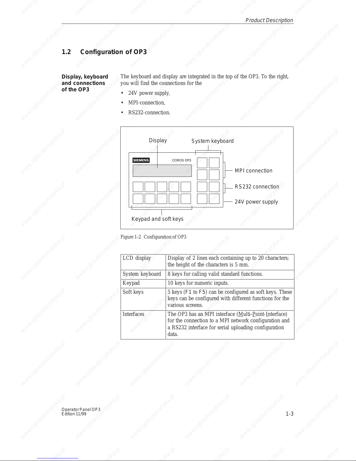
1.2 Configuration of OP3
The keyboard and display are integrated in the top of the OP3. To the right,
you will find the connections for the
• 24V power supply,
• MPI-connection,
• RS232-connection.
COROS OP3
MPI connection
Keypad and soft keys
Display
System keyboard
24V power supply
RS232 connection
Figure 1-2 Configuration of OP3
LCD display Display of 2 lines each containing up to 20 characters;
the height of the characters is 5 mm.
System keyboard 8 keys for calling valid standard functions.
Keypad 10 keys for numeric inputs.
Soft keys 5 keys (F1 to F5) can be configured as soft keys. These
keys can be configured with different functions for the
various screens.
Interfaces The OP3 has an MPI interface (Multi-Point-Interface)
for the connection to a MPI network configuration and
a RS232 interface for serial uploading configuration
data.
Display, keyboard
and connections
of the OP3
Product Description

1-4
Operator Panel OP3
Edition 11/99
Product Description
2-1
Operator Panel OP3
Edition 11/99
Functionality
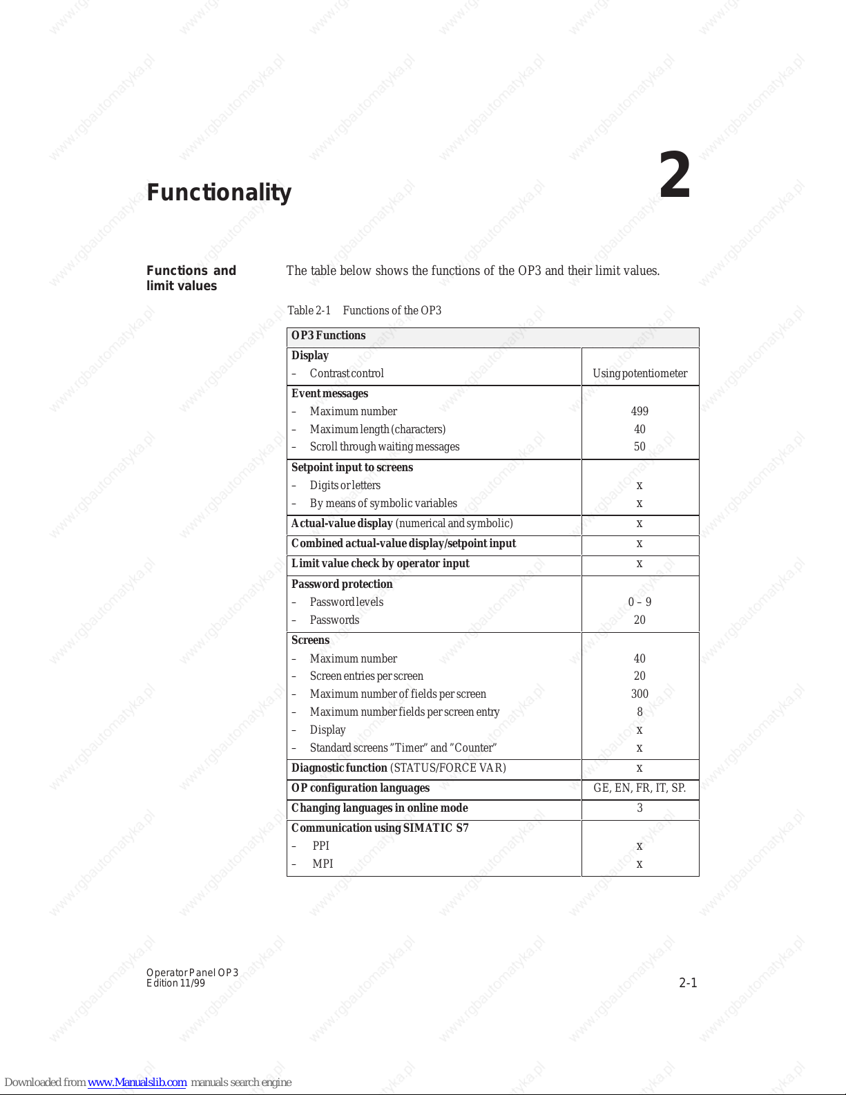
The table below shows the functions of the OP3 and their limit values.
T able 2-1 Functions of the OP3
OP3 Functions
ББББББББББББББ
Á
Display
– Contrast control
БББББ
Á
Using potentiometer
ББББББББББББББ
Á
ББББББББББББББ
Á
Event messages
– Maximum number
– Maximum length (characters)
– Scroll through waiting messages
БББББ
Á
БББББ
Á
499
40
50
ББББББББББББББ
Á
ББББББББББББББ
Á
Setpoint input to screens
– Digits or letters
– By means of symbolic variables
БББББ
Á
БББББ
Á
x
x
Actual-value display (numerical and symbolic)
x
Combined actual-value display/setpoint input
x
Limit value check by operator input
x
ББББББББББББББ
Á
ББББББББББББББ
Á
Password protection
– Password levels
– Passwords
БББББ
Á
БББББ
Á
0 – 9
20
ББББББББББББББ
Á
ББББББББББББББ
Á
ББББББББББББББ
Á
ББББББББББББББ
Á
ББББББББББББББ
Á
ББББББББББББББ
Á
Screens
– Maximum number
– Screen entries per screen
– Maximum number of fields per screen
– Maximum number fields per screen entry
– Display
– Standard screens ”Timer” and ”Counter”
БББББ
Á
БББББ
Á
БББББ
Á
БББББ
Á
БББББ
Á
БББББ
Á
40
20
300
8
x
x
Diagnostic function (ST ATUS/FORCE VAR)
x
OP configuration languages
GE, EN, FR, IT , SP.
Changing languages in online mode
3
ББББББББББББББ
Á
Communication using SIMA TIC S7
– PPI
– MPI
БББББ
Á
x
x
Functions and
limit values
2

2-2
Operator Panel OP3
Edition 11/99
T able 2-1 Functions of the OP3
OP3 Functions
ББББББББББББББ
Á
ББББББББББББББ
Á
ББББББББББББББ
Á
Connection OP3 ↔ SIMA TIC S7
– Number of PLCs that connect to a OP3
– Number of OP3s that connect to a S7-200
– Number of OP3s that connect to a S7-300
БББББ
Á
БББББ
Á
БББББ
Á
2
1
3
Functionalit
y
FUNCTIONS OF THE OP3
3 General Operation
4 Using the OP3 with Its Standard Functions
5 Screens
6 Password Protection
7 Messages
8 Timers and Counters
9 STATUS VAR and FORCE VAR Functions with the OP3
10 System Settings on Standard Screens
11 Process-Dependent Operator Guidance
12 Communication
Part II

2-2
Operator Panel OP3
Edition 11/99
3-1
Operator Panel OP3
Edition 11/99
General Operation
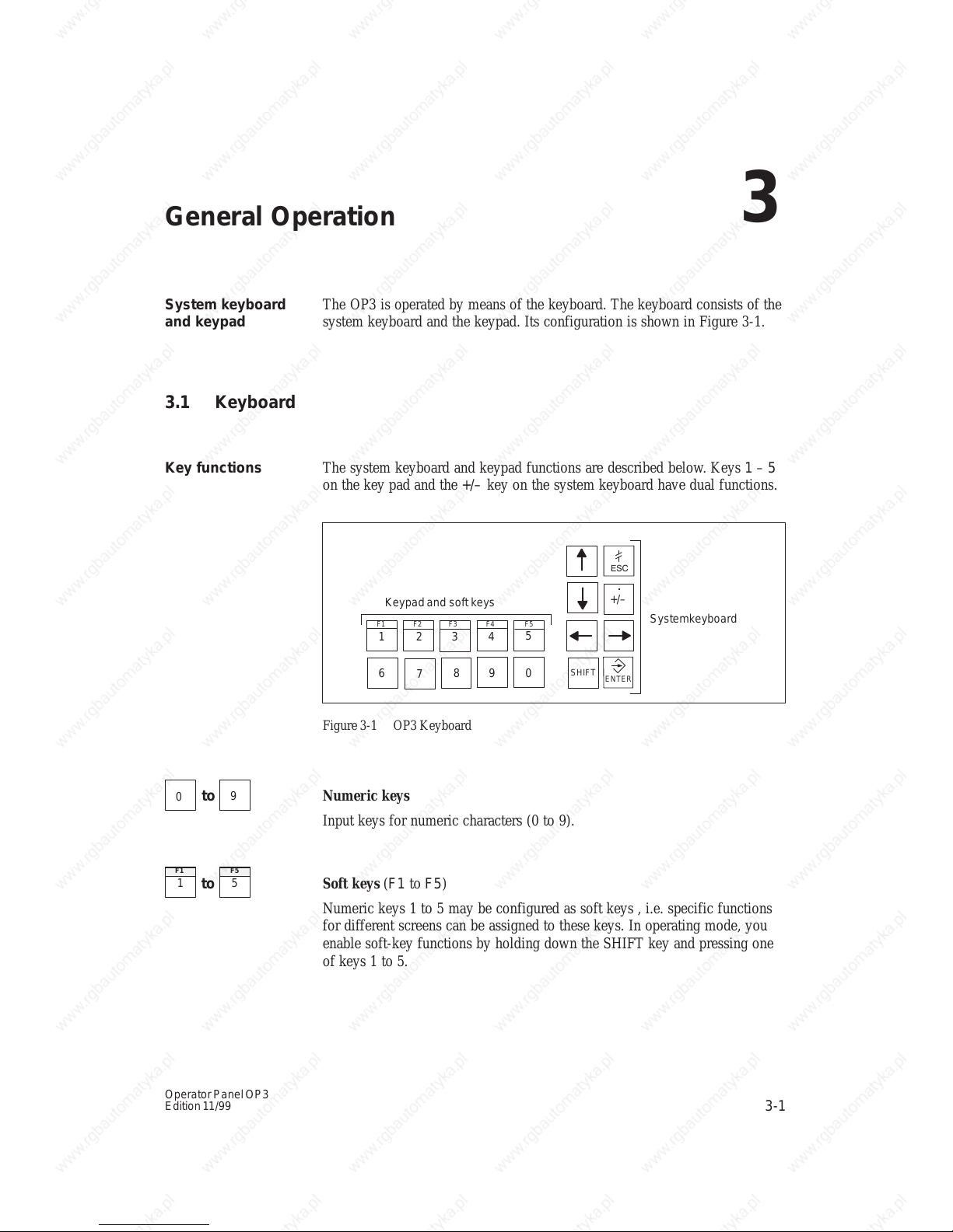
The OP3 is operated by means of the keyboard. The keyboard consists of the
system keyboard and the keypad. Its configuration is shown in Figure 3-1.
3.1 Keyboard
The system keyboard and keypad functions are described below. Keys 1 – 5
on the key pad and the +/– key on the system keyboard have dual functions.
0
1 2
3
4
5
6
7
8
9
SHIFT
ENTER
+/–
ESC
Keypad and soft keys
Systemkeyboard
.
F1 F2 F3 F4 F5
Figure 3-1 OP3 Keyboard
0
to
9
Numeric keys
Input keys for numeric characters (0 to 9).
1
F1
to
5
F5
Soft keys (F1 to F5)
Numeric keys 1 to 5 may be configured as soft keys , i.e. specific functions
for different screens can be assigned to these keys. In operating mode, you
enable soft-key functions by holding down the SHIFT key and pressing one
of keys 1 to 5.
System keyboard
and keypad
Key functions
3

3-2
Operator Panel OP3
Edition 11/99
SHIFT
SHIFT key
Switch to the second function of the dual-assignment keys.
To do this, the SHIFT key is pressed si m ult ane ously wi th the other ke y
concerned - for example:
Decimal point : Press
SHIFT
+
+/–
.
Soft-key function: Press
SHIFT
+
3
F3
+/–
.
Sign key
Change of sign from ”Plus” to ”Minus” and vice versa.
Second function (with pressed SHIFT key):
input of a decimal point.
ENTER
ENTER key
With this key you confirm and terminate your input.
With ENTER you also change from message level to screen level.
ESC
ESCAPE key
Undo:
Undoes entries in fields provided they have not been confirmed with
ENTER.
Branch back:
Branches back from a screen to the configured cross-jump destination (by
default, the last position called), or go from the start screen to message level.
Reset when scrolling through messages:
Cancels scrolling through waiting messages to reset the display to the
currently waiting message.
Hide a system message.
Arrow keys
Move the cursor. Depending on the operating situation, the cursor is moved
one character, field, entry or display to the left, right, up or down.
General Operation
3-3
Operator Panel OP3
Edition 11/99
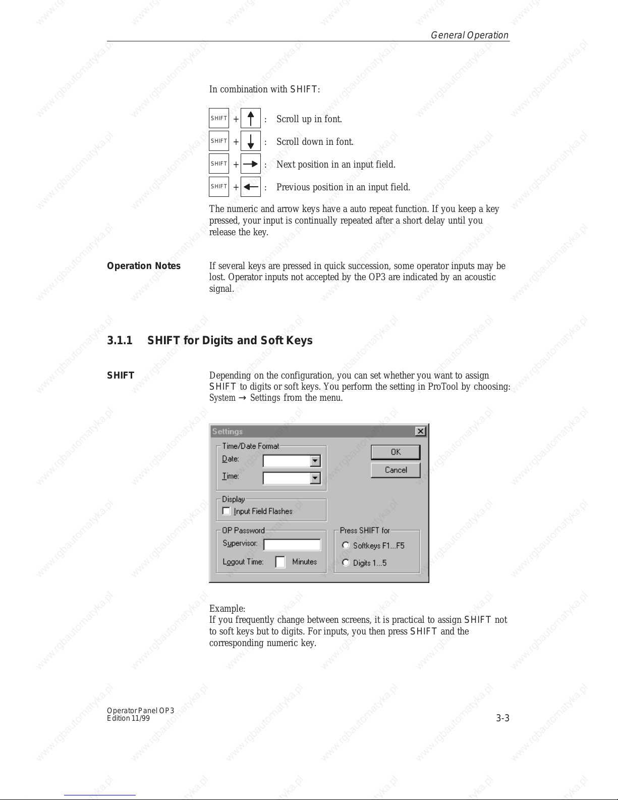
In combination with SHIFT:
SHIFT
+ : Scroll up in font.
SHIFT
+ : Scroll down in font.
SHIFT
+ : Next position in an input field.
SHIFT
+ : Previous position in an input field.
The numeric and arrow keys have a auto repeat function. If you keep a key
pressed, your input is continually repeated after a short delay until you
release the key.
If several keys are pressed in quick succession, some operator inputs may be
lost. Operator inputs not accepted by the OP3 are indicated by an acoustic
signal.
3.1.1 SHIFT for Digits and Soft Keys
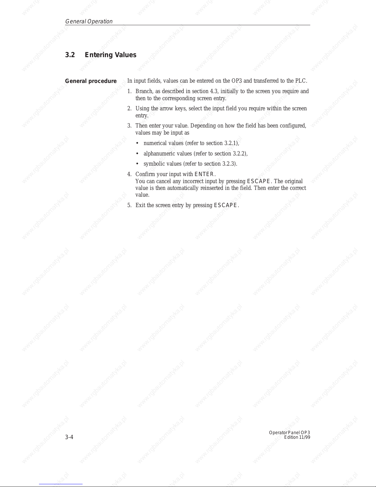
Depending on the configuration, you can set whether you want to assign
SHIFT to digits or soft keys. You perform the setting in ProTool by choosing:
System → Settings from the menu.
Example:
If you frequently change between screens, it is practical to assign SHIFT not
to soft keys but to digits. For inputs, you then press SHIFT and the
corresponding numeric key.
Operation Notes
SHIFT
General Operation
3-4
Operator Panel OP3
Edition 11/99
3.2 Entering Values
In input fields, values can be entered on the OP3 and transferred to the PLC.
1. Branch, as described in section 4.3, initially to the screen you require and
then to the corresponding screen entry.
2. Using the arrow keys, select the input field you require within the screen
entry.
3. Then enter your value. Depending on how the field has been configured,
values may be input as
• numerical values (refer to section 3.2.1),
• alphanumeric values (refer to section 3.2.2),
• symbolic values (refer to section 3.2.3).
4. Confirm your input with ENTER.
You can cancel any incorrect input by pressing ESCAPE . The original
value is then automatically reinserted in the field. Then enter the correct
value.
5. Exit the screen entry by pressing ESCAPE.
General procedure
General Operation
3-5
Operator Panel OP3
Edition 11/99
3.2.1 Entering Numerical Values
In fields that allow the operator to enter a numerical value, you enter the
numerical value character by character on the keypad.
You enter a decimal point by pressing the SHIFT key and the sign key
simultaneously.
If there is a value in the field already, it is cleared completely from the field
when the first character is entered. Once input has started, you cannot exit
from the input field until the input has been entered or canceled.
In numerical fields (not in hexadecimal format), input is usually
right-justified. Digits that have already been entered are moved to the left
(pocket calculator format).
Exception:
Input fields for setpoints in bit pattern format – for instance, when calling the
PU functions STATUS/FORCE VAR – are changed to left-justified. When
input begins, the old value does not disappear from the display completely
but its bit pattern is overwritten one character at a time. You move the cursor
in this type of field by simultaneously pressing the SHIFT key and an arrow
key (← or →).
You can configure limit values for numerical input fields. In this type of
field, a limit value check takes place. Entered values are applied only if they
are within the configured limits. If a value outside these limits is entered, a
system message is displayed and, after it has been canceled, the old value is
displayed again.
If a numerical field has been configured with a certain number of decimal
places and if, after you confirmed your input, too many have been entered,
the extra ones are ignored; if too few have been entered, the field is fitted
with zeros.
Entering values
with a decimal
point
Changing
numerical values
Right-justified
input
Limit value check
Decimal places
General Operation
3-6
Operator Panel OP3
Edition 11/99
3.2.2 Entering Alphanumeric Values
In an input of alphanumeric values, digits and letters are mixed.
For the numerical components of the input, proceed as described in section
3.2.1. If, however, you wish to enter a letter at the current cursor position,
you must enable the alphanumeric character set.
To enter the string 18OCT61, for example, proceed as follows:
1. Enter 1 and 8 by means of the keypad.
2. Press the SHIFT key and hold it down.
The extended character set becomes available.
3. Scroll with the UP or DOWN arrow key through the extended character
set.
4. Select O and move right one position using the RIGHT arrow key.
The charact er you sel ect ed is applie d by movi ng the cursor.
5. Select C and move right one position using the RIGHT arrow key.
6. Select T and move right one position using the RIGHT arrow key.
7. Release the SHIFT key. The extended character set is de-activated.
8. Enter the remaining figures 6 and 1 by means of the keypad and confirm
your input by pressing the ENTER key.
3.2.3 Entering Symbolic Values
In the case of a symbolic input of a value, text is displayed or typed instead
of the value. If a field has to be filled in using a symbolic entry for a value,
then apply the text from a list box. To do this, proceed as follows:
1. Press SHIFT in the input fi eld and hold it down.
The list box with its configured symbolic inputs is activated.
2. With the cursor keys, select the text you require.
3. Release SHIFT.
4. Confirm your selection by pressing ENTER.
Mixed input of
digits and letters
Example
Text instead of a
value
General Operation
4-1
Operator Panel OP3
Edition 11/99
Using the OP3 with Its Standard Functions
The configuration software ProTool, includes a configuration which contains
standard screens. You can choose all the functions required for operating the
OP3 by using these standard screens. The different functions are described in
this manual with reference to the standard screens.
The English-language standard screens, which are loaded from the firmware
of the OP3, remain active, once you have switched on the operating voltage,
until a configuration is loaded (refer to section 4.2).
4.1 Operating Levels
In OP3 operation, you have to distinguish between two distinct operating
levels, between which you can switch:
• Message level
At the message level, current messages are displayed.
• Screen level
At the screen level, functions are chosen, serviced and executed.
The message level is the highest level on the OP3. At message level, waiting
event messages and system messages are displayed. After the OP3 starts up,
it changes to message level and displays the standby message.
The screen level is reached by pressing the ENTER key. The first screen to
be called is the start screen. From the start screen you branch, depending on
the configuration, to other screens. On the screens, you view the actual
process values, and you can enter values and initiate functions by means of
soft keys.
The linking of individual screens is referred to as a screen hierarchy. As you
go further down the screen hierarchy, you go stage by stage right back to the
start screen by pressing the ESCAPE key. From here you can return to the
message level by pressing the ESCAPE key. You can also return directly to
the message level from a screen, depending on the configuration.
Using the standard
screens
Message level and
screen level
Screen hierarchy
4
4-2
Operator Panel OP3
Edition 11/99
The change from screen level to message level, or back again, is either
manual or automatic.
You press the appropriate key and change the operating level
• from message level to screen level by pressing the ENTER key,
• from screen level to message level by pressing the ESCAPE key.
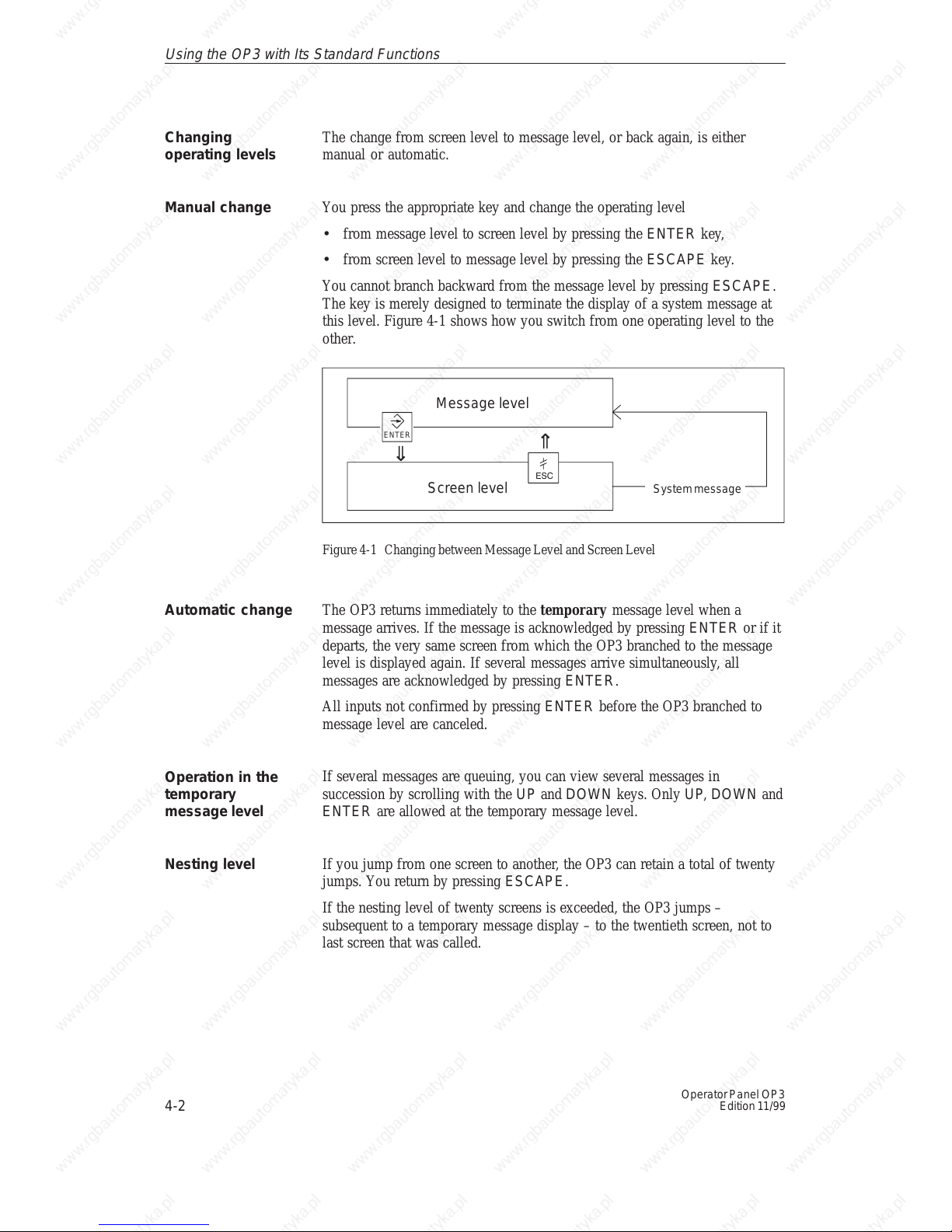
You cannot branch backward from the message level by pressing ESCAPE .
The key is merely designed to terminate the display of a system message at
this level. Figure 4-1 shows how you switch from one operating level to the
other.
Message level
Screen level
⇓
⇑
ESC
System message
ENTER
Figure 4-1 Changing between Message Level and Screen Level
The OP3 returns immediately to the temporary message level when a
message arrives. If the message is acknowledged by pressing ENTER or if it
departs, the very same screen from which the OP3 branched to the message
level is displayed again. If several messages arrive simultaneously, all
messages are acknowledged by pressing ENTER.
All inputs not confirmed by pressing ENTER before the OP3 branched to
message level are canceled.
If several messages are queuing, you can view several messages in
succession by scrolling with the UP and DOWN keys. Only UP, DOWN and
ENTER are allowed at the temporary message level.
If you jump from one screen to another, the OP3 can retain a total of twenty
jumps. You return by pressing ESCAPE.
If the nesting level of twenty screens is exceeded, the OP3 jumps –
subsequent to a temporary message display – to the twentieth screen, not to
last screen that was called.
Changing
operating levels
Manual change
Automatic change
Operation in the
temporary
message level
Nesting level
Using the OP3 with Its Standard Functions
 Loading...