

Siemens simatic hmi op27, simatic hmi op37 Equipment Manual

Artisan Technology Group is your source for quality
new and certied-used/pre-owned equipment
• FAST SHIPPING AND
DELIVERY
• TENS OF THOUSANDS OF
IN-STOCK ITEMS
• EQUIPMENT DEMOS
• HUNDREDS OF
MANUFACTURERS
SUPPORTED
• LEASING/MONTHLY
RENTALS
• ITAR CERTIFIED
SECURE ASSET SOLUTIONS
SERVICE CENTER REPAIRS
Experienced engineers and technicians on staff
at our full-service, in-house repair center
WE BUY USED EQUIPMENT
Sell your excess, underutilized, and idle used equipment
We also offer credit for buy-backs and trade-ins
www.artisantg.com/WeBuyEquipment
REMOTE INSPECTION
Remotely inspect equipment before purchasing with
our interactive website at www.instraview.com
LOOKING FOR MORE INFORMATION?
Visit us on the web at www.artisantg.com for more
information on price quotations, drivers, technical
specications, manuals, and documentation
Contact us: (888) 88-SOURCE | sales@artisantg.com | www.artisantg.com
SM
View
Instra

Preface, Contents
Part I Introduction
1
2
Part II Functions
3
11
Part III Installation and
Commissioning
12
15
Part IV Equipment Description
and Maintenance
16
19
Part V Appendices
A
F
Glossary, Index
Release 05/99
OP27, OP37
Operator Panels
Equipment Manual
SIMATIC HMI
6AV3991–1AK01–0AB0
Artisan Technology Group - Quality Instrumentation ... Guaranteed | (888) 88-SOURCE | www.artisantg.com

This manual contains notices which you should observe to ensure your own personal safety, as
well as to protect the product and connected equipment. These notices are highlighted in the
manual by a warning triangle and are marked as follows according to the level of danger:
!
Warning
indicates that death, severe personal injury or substantial property damage can result if proper
precautions are not taken.
!
Caution
indicates that minor personal injury or property damage can result if proper precautions are not
taken.
Note
draws your attention to particularly important information on the product, handling the product,
or to a particular part of the documentation.
Equipment may be commissioned and operated only by qualified personnel. Qualified personnel within the meaning of the safety notices in this manual are persons who are authorized to
commission, ground and identify equipment, systems and circuits in accordance with safety
engineering standards.
Note the following:
!
Warning
The equipment may be used only for the applications stipulated in the catalog and in the technical description and only in conjunction with other equipment and components recommended
or approved by Siemens.
Startup must not take place until it is established that the machine, which is to accommodate
this component, is in conformity with the guideline 89/392/EEC.
Faultless and safe operation of the product presupposes proper transportation, proper storage,
erection and installation as well as careful operation and maintenance.
The approvals that apply to the device are detailed in the Chapter Technical Data.
SIMATICR, ProTool/LiteR, ProToolR and ProTool/ProR
are registered trademarks of
Siemens AG.
Some of the other designations used in these documents are also registered trademarks; the
owner’s rights may be violated if they are used be third parties for their own purposes.
Editor and Publisher: A&D PT1
W
e have checked the contents of this manual for agreement with
the
hardware and software described. Since deviations cannot be
precluded
entirely
, we cannot guarantee full agreement. However
,
the
data in this manual are reviewed regularly and any necessary
corrections included in subsequent editions. Suggestions for
improvement
are welcomed.
T
echnical data subject to change.
E
Siemens
AG 1999
Disclaimer of Liability
Copyright E
Siemens
AG 1999 All rights reserved
The reproduction, transmission or use of this document or its
contents is not permitted without express written authority.
Offenders will be liable for damages. All rights, including rights
created
by patent grant or registration of
a utility model or design,
are reserved.
Siemens AG,
Bereich Automation & Drives
SIMA
TIC Human Machine Interface
A&D PT1
Postfach 4848,
D-90327 Nuernberg
Siemens Aktiengesellschaft
Order No. 6A
V3991–1AK01–0AB0
Safety
Guidelines
Qualified Personnel
Correct Usage
Approvals
Trademarks
Impressum
Artisan Technology Group - Quality Instrumentation ... Guaranteed | (888) 88-SOURCE | www.artisantg.com

i
OP27,
OP37 Equipment Manual
Release 05/99
Preface
This
equipment manual provides operation, installation, configuration and sys
-
tem personnel with information concerning functionality
, operation and techni
-
cal design of the Operator Panels OP27 and OP37.
The ”OP27 , OP37 Operator Panel” equipment manual is or
ganized into the
following chapters:
Part Chapters Contents
I
1 - 2
Overview of features and functional scope of the
OP in tabular form.
II
3 - 1
1
Step-by–step instructions on how to operate the OP
using the standard screens.
III
12 - 15
–
Mechanical and electrical installation,
– Commissioning
–
OP37 in DOS Mode
IV
16 - 19
Detailed information on the OP and its
maintenance.
V Appendix
A – F
–T
echnical data,
–
Interface assignments,
–
Hardware test,
–
System messages,
– SIMA
TIC HMI documentation,
–
ESD guidelines,
–
Glossary of terms
The following conventions are used throughout this manual:
Motor off Text
which appears in the OP display is presented in
this typewriter font.
Variable
Symbolic names representing variable values on the
screen are presented in this italic typewriter font
Screens
Functions selected by the user are presented in this
standard italic font.
ESC
The labels of buttons are presented in a dif
ferent
font.
Purpose
Organization of the
manual
Conventions
Artisan Technology Group - Quality Instrumentation ... Guaranteed | (888) 88-SOURCE | www.artisantg.com

ii
OP27,
OP37 Equipment Manual
Release 05/99
The
various releases of the equipment manual correspond to the following
firmware and versions:
i
Rel
ease
R
emarks
ProTool V
ersion
09/96
First release of the OP37 equipment
manual
V 2.5 and later
11/97
Inclusion of the OP27 and revision
according to the new documentation
concept
V 4.0 and later
05/99
New standard screen for printing
messages; troubleshooting
V 5.0 and later
History
Preface
Artisan Technology Group - Quality Instrumentation ... Guaranteed | (888) 88-SOURCE | www.artisantg.com

iii
OP27,
OP37 Equipment Manual
Release 05/99
In
the case of technical queries, please contact your local Siemens in the sub
sidiaries and branches responsible for your area. Refer to Appendix E of this
equipment manual for a list of addresses.
SIMATIC Customer Support Hotline
Available worldwide, at all times:
Johnson City
Nuernberg
Singapur
Simatic
Basic Hotline
Nuernberg
SIMATIC BASIC Hotline
Johnson City
SIMATIC BASIC Hotline
Singapur
SIMATIC BASIC Hotline
Local
time:
Mon - Fri 8:00 to 18:00
T
elephone:
+49 (911) 895-7000
Fax:
+49 (911) 895-7002
E-Mail: simatic.support@
nbgm.siemens.de
Local time:
Mon - Fri 8:00 to 17:00
T
elephone:
+1 423 461-2522
Fax:
+1 423 461-2231
E-Mail: simatic.hotline@
sea.siemens.com
Local time:
Mon - Fri 8:00 to 17:30
T
elephone:
+65 740-7000
Fax:
+65 740-7001
E-Mail: simatic@
singnet.com.sg
SIMATIC
Premium Hotline
(charged,
only with
SIMA
TIC Card)
T
ime:
Mon - Fri 0:00 to 24:00
T
elephone:
+49 (911) 895-7777
Fax:
+49 (911) 895-7001
Other support
Preface
Artisan Technology Group - Quality Instrumentation ... Guaranteed | (888) 88-SOURCE | www.artisantg.com

iv
OP27,
OP37 Equipment Manual
Release 05/99
SIMATIC Customer Online Services
SIMATIC
Customer Support offers comprehensive additional information
concerning SIMA
TIC products through its Online services as follows:
Up–to–date
general information is provided
–
in
Internet
under
http://www.ad.siemens.de/simatic
–
via
Fax-Polling
under 08765-93 02 77 95 00
Up–to–date product information and downloads for practical use can be found:
–
in
Internet
unter
http://www.ad.siemens.de/support/
html–00/
–
via the
Bulletin Board System
(BBS) in Nürnber
g (SIMA
TIC Customer
Support Mailbox)
under
+49 (911) 895–7100
In
order to contact the mailbox, please use a modem with up to
28.8
kBaud (V
.34) capacity
. Set the parameters as follows: 8, N, 1,
ANSI, or dial for connection via ISDN (x.75, 64 kBit).
Preface
Artisan Technology Group - Quality Instrumentation ... Guaranteed | (888) 88-SOURCE | www.artisantg.com

v
OP27,
OP37 Equipment Manual
Release 05/99
The
abbreviations used in this equipment manual
have the following meaning:
AM
Alarm Message
ANSI
American National Standards Institute
AS511
Protocol of the PU interface to SIMA
TIC S5
ASCII
American Standard Code for Information Interchange
AU
Automation Unit
CPI
Control Panel Interface
CPU
Central Processing Unit
DIL
Dual-In-Line (package)
DP
Decentral Periphery
DRAM
Dynamic Random Access Memory
DKM
Direct Key Module
EM
Event Message
ESD
Electrostatic Sensitive Device
JEIDA
Japan Electronic Industry Development Asociation
LCD
Liquid Crystal Display
LED
Light–Emitting Diode
MPI
Multipoint Interface (SIMA
TIC S7)
PC
Personal Computer
PCMCIA
PLC
Personal Computer Memory Card International Association
Programmable Logic Controller
PU
Programming Unit
PPI
Point to Point Interface (SIMA
TIC S7)
SRAM
Static Random Access Memory
STN
Super T
wisted Nematic
TFT
Thin Film T
ransistor
TP T
ouch Panel
TTL Transistor-T
ransistor Logic
Abbreviations
Preface
Artisan Technology Group - Quality Instrumentation ... Guaranteed | (888) 88-SOURCE | www.artisantg.com

vi
OP27,
OP37 Equipment Manual
Release 05/99
Preface
Artisan Technology Group - Quality Instrumentation ... Guaranteed | (888) 88-SOURCE | www.artisantg.com

i
OP27, OP37 Equipment Manual
Release 05/99
Contents
Part I: Introduction
1 Product
Description
1-1.
. . . . . . . . . . . . . . . . . . . . . . . . . . . . . . . . . . . . . . . . . . . . . . . . . . . .
1.1 Visualizing
and Controlling Processes
1-3.
. . . . . . . . . . . . . . . . . . . . . . . . . . . . .
1.2 The
OPs at a Glance
1-6.
. . . . . . . . . . . . . . . . . . . . . . . . . . . . . . . . . . . . . . . . . . . .
2 Functionalty 2-1
. . . . . . . . . . . . . . . . . . . . . . . . . . . . . . . . . . . . . . . . . . . . . . . . . . . . . . . . . . . .
Part II: Functions
3 General Operation 3-1.
. . . . . . . . . . . . . . . . . . . . . . . . . . . . . . . . . . . . . . . . . . . . . . . . . . . . . .
3.1 Changing
the Active Window
3-3.
. . . . . . . . . . . . . . . . . . . . . . . . . . . . . . . . . . . . .
3.2 Integrated
Keyboard
3-4.
. . . . . . . . . . . . . . . . . . . . . . . . . . . . . . . . . . . . . . . . . . . . .
3.3 Enter Values 3-8.
. . . . . . . . . . . . . . . . . . . . . . . . . . . . . . . . . . . . . . . . . . . . . . . . . . .
3.3.1 Entering
Numeric V
alues 3-9.
. . . . . . . . . . . . . . . . . . . . . . . . . . . . . . . . . . . . . . . . .
3.3.2 Entering
Alphanumeric V
alues 3-10.
. . . . . . . . . . . . . . . . . . . . . . . . . . . . . . . . . . . .
3.3.3 Entering
Symbolic V
alues 3-11.
. . . . . . . . . . . . . . . . . . . . . . . . . . . . . . . . . . . . . . . .
3.4 Help Text 3-14.
. . . . . . . . . . . . . . . . . . . . . . . . . . . . . . . . . . . . . . . . . . . . . . . . . . . . . .
4 Screens 4-1
. . . . . . . . . . . . . . . . . . . . . . . . . . . . . . . . . . . . . . . . . . . . . . . . . . . . . . . . . . . . . . . . .
4.1 Screen
Elements
4-1.
. . . . . . . . . . . . . . . . . . . . . . . . . . . . . . . . . . . . . . . . . . . . . . . .
4.2 Standard
Screens
4-3.
. . . . . . . . . . . . . . . . . . . . . . . . . . . . . . . . . . . . . . . . . . . . . . .
5 Password
Protection
5-1.
. . . . . . . . . . . . . . . . . . . . . . . . . . . . . . . . . . . . . . . . . . . . . . . . . . .
5.1 Password
Level and Access Permissions
5-1.
. . . . . . . . . . . . . . . . . . . . . . . . . .
5.2 Logging
In and Out on the OP
5-3.
. . . . . . . . . . . . . . . . . . . . . . . . . . . . . . . . . . . .
5.3 Password
Management
5-4.
. . . . . . . . . . . . . . . . . . . . . . . . . . . . . . . . . . . . . . . . . .
6 Messages 6-1
. . . . . . . . . . . . . . . . . . . . . . . . . . . . . . . . . . . . . . . . . . . . . . . . . . . . . . . . . . . . . . .
6.1 Types
of Message
6-2.
. . . . . . . . . . . . . . . . . . . . . . . . . . . . . . . . . . . . . . . . . . . . . . .
6.1.1 Event
Messages and Alarm Messages
6-2.
. . . . . . . . . . . . . . . . . . . . . . . . . . . . .
6.1.2 Alarm
Messages
6-6.
. . . . . . . . . . . . . . . . . . . . . . . . . . . . . . . . . . . . . . . . . . . . . . . .
6.1.3 System
Messages
6-7.
. . . . . . . . . . . . . . . . . . . . . . . . . . . . . . . . . . . . . . . . . . . . . .
6.2 Displaying
Messages
6-8.
. . . . . . . . . . . . . . . . . . . . . . . . . . . . . . . . . . . . . . . . . . . .
6.3 Deleting
Messages
6-11.
. . . . . . . . . . . . . . . . . . . . . . . . . . . . . . . . . . . . . . . . . . . . . .
6.4 Printing
Messages
6-13.
. . . . . . . . . . . . . . . . . . . . . . . . . . . . . . . . . . . . . . . . . . . . . .
Artisan Technology Group - Quality Instrumentation ... Guaranteed | (888) 88-SOURCE | www.artisantg.com

ii
OP27, OP37 Equipment Manual
Release 05/99
6.5 Standard
Screens for Messages
6-15.
. . . . . . . . . . . . . . . . . . . . . . . . . . . . . . . . . .
6.5.1 “Edit
Message” Standard Screen
6-15.
. . . . . . . . . . . . . . . . . . . . . . . . . . . . . . . . . .
6.5.2 “Output
Messages” Standard Screen
6-17.
. . . . . . . . . . . . . . . . . . . . . . . . . . . . . .
6.5.3 “System
Settings” Standard Screen
6-19.
. . . . . . . . . . . . . . . . . . . . . . . . . . . . . . .
7 Printing 7-1
. . . . . . . . . . . . . . . . . . . . . . . . . . . . . . . . . . . . . . . . . . . . . . . . . . . . . . . . . . . . . . . . .
8 Recipes 8-1
. . . . . . . . . . . . . . . . . . . . . . . . . . . . . . . . . . . . . . . . . . . . . . . . . . . . . . . . . . . . . . . . .
8.1 Standard
Screens for Recipes
8-3.
. . . . . . . . . . . . . . . . . . . . . . . . . . . . . . . . . . . .
8.1.1 Creating,
Editing and Saving Data Records
8-8.
. . . . . . . . . . . . . . . . . . . . . . . . .
8.1.2 Transferring
Data Records
8-13.
. . . . . . . . . . . . . . . . . . . . . . . . . . . . . . . . . . . . . . .
8.2 Record
Sets
8-15.
. . . . . . . . . . . . . . . . . . . . . . . . . . . . . . . . . . . . . . . . . . . . . . . . . . . .
9 Storing and Loading Data 9-1.
. . . . . . . . . . . . . . . . . . . . . . . . . . . . . . . . . . . . . . . . . . . . . . .
9.1 Data T
ypes, Data Media and Storage Principle
9-1.
. . . . . . . . . . . . . . . . . . . . . .
9.2 Clear/Initialize
Storage Medium
9-3.
. . . . . . . . . . . . . . . . . . . . . . . . . . . . . . . . . . .
9.3 Backup/Restore 9-5
. . . . . . . . . . . . . . . . . . . . . . . . . . . . . . . . . . . . . . . . . . . . . . . . . .
10 Status/Force T
ag Using the OP
10-1.
. . . . . . . . . . . . . . . . . . . . . . . . . . . . . . . . . . . . . . . . . .
10.1 Status Tag 10-2.
. . . . . . . . . . . . . . . . . . . . . . . . . . . . . . . . . . . . . . . . . . . . . . . . . . . . .
10.2 Force Tag 10-5.
. . . . . . . . . . . . . . . . . . . . . . . . . . . . . . . . . . . . . . . . . . . . . . . . . . . . . .
11 System Settings 11-1.
. . . . . . . . . . . . . . . . . . . . . . . . . . . . . . . . . . . . . . . . . . . . . . . . . . . . . . . .
11.1 Setting
an Operating Mode
11-3.
. . . . . . . . . . . . . . . . . . . . . . . . . . . . . . . . . . . . . . .
11.2 Blanking
the Screen
11-4.
. . . . . . . . . . . . . . . . . . . . . . . . . . . . . . . . . . . . . . . . . . . . .
11.3 Other
Settings
11-5.
. . . . . . . . . . . . . . . . . . . . . . . . . . . . . . . . . . . . . . . . . . . . . . . . . .
Part III: Installation and Commissioning
12 Mechanical Installation 12-1.
. . . . . . . . . . . . . . . . . . . . . . . . . . . . . . . . . . . . . . . . . . . . . . . . .
12.1 Installing
the OP27
12-2.
. . . . . . . . . . . . . . . . . . . . . . . . . . . . . . . . . . . . . . . . . . . . . .
12.2 Installing
the OP37
12-3.
. . . . . . . . . . . . . . . . . . . . . . . . . . . . . . . . . . . . . . . . . . . . . .
13 Electrical Installation 13-1.
. . . . . . . . . . . . . . . . . . . . . . . . . . . . . . . . . . . . . . . . . . . . . . . . . . .
13.1 Power
Supply and Relay Contacts
13-3.
. . . . . . . . . . . . . . . . . . . . . . . . . . . . . . . .
13.1.1 Connecting
the Configuration Computer
13-4.
. . . . . . . . . . . . . . . . . . . . . . . . . . .
13.1.2 Connecting
the PLC
13-5.
. . . . . . . . . . . . . . . . . . . . . . . . . . . . . . . . . . . . . . . . . . . . .
13.1.3 Connecting
a Printer
13-7.
. . . . . . . . . . . . . . . . . . . . . . . . . . . . . . . . . . . . . . . . . . . . .
14 Commissioning 14-1
. . . . . . . . . . . . . . . . . . . . . . . . . . . . . . . . . . . . . . . . . . . . . . . . . . . . . . . . .
14.1 Initial
Startup
14-2.
. . . . . . . . . . . . . . . . . . . . . . . . . . . . . . . . . . . . . . . . . . . . . . . . . . .
14.2 Recommissioning 14-3
. . . . . . . . . . . . . . . . . . . . . . . . . . . . . . . . . . . . . . . . . . . . . . . .
14.3 Startup
Behavior
14-6.
. . . . . . . . . . . . . . . . . . . . . . . . . . . . . . . . . . . . . . . . . . . . . . . .
14.4 Testing
a Configuration in OFFLINE Mode
14-7.
. . . . . . . . . . . . . . . . . . . . . . . . . .
14.5 Testing
the Configuration in Conjunction with the PLC
14-8.
. . . . . . . . . . . . . . .
Contents
Artisan Technology Group - Quality Instrumentation ... Guaranteed | (888) 88-SOURCE | www.artisantg.com

iii
OP27, OP37 Equipment Manual
Release 05/99
15 OP37
in DOS Mode
15-1.
. . . . . . . . . . . . . . . . . . . . . . . . . . . . . . . . . . . . . . . . . . . . . . . . . . . . .
15.1 Specific
OP37 Settings in BIOS Setup
15-2.
. . . . . . . . . . . . . . . . . . . . . . . . . . . . .
15.2 Changing
Between OP and DOS Modes
15-4.
. . . . . . . . . . . . . . . . . . . . . . . . . . .
Part IV: Equipment Description and Maintenance
16 OP27
Unit Description
16-1.
. . . . . . . . . . . . . . . . . . . . . . . . . . . . . . . . . . . . . . . . . . . . . . . . . .
16.1 Dimensions 16-1
. . . . . . . . . . . . . . . . . . . . . . . . . . . . . . . . . . . . . . . . . . . . . . . . . . . . .
16.2 Operating
and Display Elements
16-2.
. . . . . . . . . . . . . . . . . . . . . . . . . . . . . . . . . .
16.3 Connection
Elements
16-3.
. . . . . . . . . . . . . . . . . . . . . . . . . . . . . . . . . . . . . . . . . . . .
16.4 Communication
Options
16-4.
. . . . . . . . . . . . . . . . . . . . . . . . . . . . . . . . . . . . . . . . .
16.5 Labeling
Function Keys
16-5.
. . . . . . . . . . . . . . . . . . . . . . . . . . . . . . . . . . . . . . . . . .
17 OP37
Unit Description
17-1.
. . . . . . . . . . . . . . . . . . . . . . . . . . . . . . . . . . . . . . . . . . . . . . . . . .
17.1 Dimensions 17-2
. . . . . . . . . . . . . . . . . . . . . . . . . . . . . . . . . . . . . . . . . . . . . . . . . . . . .
17.2 Operating
and Display Elements
17-3.
. . . . . . . . . . . . . . . . . . . . . . . . . . . . . . . . . .
17.3 Connection
Elements
17-4.
. . . . . . . . . . . . . . . . . . . . . . . . . . . . . . . . . . . . . . . . . . . .
17.4 Communication
Options
17-5.
. . . . . . . . . . . . . . . . . . . . . . . . . . . . . . . . . . . . . . . . .
17.5 Labeling
Function Keys
17-6.
. . . . . . . . . . . . . . . . . . . . . . . . . . . . . . . . . . . . . . . . . .
18 Options 18-1
. . . . . . . . . . . . . . . . . . . . . . . . . . . . . . . . . . . . . . . . . . . . . . . . . . . . . . . . . . . . . . . . .
18.1 AT
Expansion Slot (OP37 only)
18-2.
. . . . . . . . . . . . . . . . . . . . . . . . . . . . . . . . . . .
18.2 Direct
Key Module
18-4.
. . . . . . . . . . . . . . . . . . . . . . . . . . . . . . . . . . . . . . . . . . . . . .
18.2.1 Installing
the Direct Key Module
18-5.
. . . . . . . . . . . . . . . . . . . . . . . . . . . . . . . . . . .
18.2.2 Connection
and Adjusting Elements
18-7.
. . . . . . . . . . . . . . . . . . . . . . . . . . . . . . .
18.3 Control
Panel Interface
18-10.
. . . . . . . . . . . . . . . . . . . . . . . . . . . . . . . . . . . . . . . . . .
18.3.1 Installing
the Control Panel Interface
18-11.
. . . . . . . . . . . . . . . . . . . . . . . . . . . . . . .
18.3.2 Connection
and Adjusting Elements
18-14.
. . . . . . . . . . . . . . . . . . . . . . . . . . . . . . .
19 Maintenance/Upkeep 19-1
. . . . . . . . . . . . . . . . . . . . . . . . . . . . . . . . . . . . . . . . . . . . . . . . . . . .
19.1 Cleaning
the Screen and Keyboard Overlay
19-1.
. . . . . . . . . . . . . . . . . . . . . . . .
19.2 Replacing
the Backup Battery
19-2.
. . . . . . . . . . . . . . . . . . . . . . . . . . . . . . . . . . . .
19.3 Other
Maintenance W
ork on OP27
19-4.
. . . . . . . . . . . . . . . . . . . . . . . . . . . . . . . .
19.3.1 Replacing
the Display on the OP27M
19-5.
. . . . . . . . . . . . . . . . . . . . . . . . . . . . . .
19.3.2 Replacing
the Back-Lighting of the OP27C
19-7.
. . . . . . . . . . . . . . . . . . . . . . . . .
19.4 Other
Maintenance W
ork on OP37
19-10.
. . . . . . . . . . . . . . . . . . . . . . . . . . . . . . . .
19.4.1 Opening
the OP37 Housing
19-10.
. . . . . . . . . . . . . . . . . . . . . . . . . . . . . . . . . . . . . .
19.4.2 Replacing
the Back-Lighting of the OP37
19-12.
. . . . . . . . . . . . . . . . . . . . . . . . . . .
19.4.3 Replacing
the Floppy Disk Drive
19-14.
. . . . . . . . . . . . . . . . . . . . . . . . . . . . . . . . . .
Contents
Artisan Technology Group - Quality Instrumentation ... Guaranteed | (888) 88-SOURCE | www.artisantg.com

iv
OP27, OP37 Equipment Manual
Release 05/99
Part V: Appendix
A Technical
Data
A-1.
. . . . . . . . . . . . . . . . . . . . . . . . . . . . . . . . . . . . . . . . . . . . . . . . . . . . . . . . .
B Interface
Assignments
B-1.
. . . . . . . . . . . . . . . . . . . . . . . . . . . . . . . . . . . . . . . . . . . . . . . . . .
C Test Functions C-1.
. . . . . . . . . . . . . . . . . . . . . . . . . . . . . . . . . . . . . . . . . . . . . . . . . . . . . . . . .
C.1 Hardware Test C-1.
. . . . . . . . . . . . . . . . . . . . . . . . . . . . . . . . . . . . . . . . . . . . . . . . . .
C.1.1 Individual Tests C-3.
. . . . . . . . . . . . . . . . . . . . . . . . . . . . . . . . . . . . . . . . . . . . . . . . .
C.1.2 Test
Adapters
C-6.
. . . . . . . . . . . . . . . . . . . . . . . . . . . . . . . . . . . . . . . . . . . . . . . . . . .
D System
Messages
D-1.
. . . . . . . . . . . . . . . . . . . . . . . . . . . . . . . . . . . . . . . . . . . . . . . . . . . . . .
E SIMATIC HMI Documentation E-1.
. . . . . . . . . . . . . . . . . . . . . . . . . . . . . . . . . . . . . . . . . . . .
F ESD Guidelines F-1.
. . . . . . . . . . . . . . . . . . . . . . . . . . . . . . . . . . . . . . . . . . . . . . . . . . . . . . . .
Contents
Artisan Technology Group - Quality Instrumentation ... Guaranteed | (888) 88-SOURCE | www.artisantg.com

INTRODUCTION
1 Product Description
2 Functionality
Part
I
Artisan Technology Group - Quality Instrumentation ... Guaranteed | (888) 88-SOURCE | www.artisantg.com

-2
OP27,
OP37 Equipment Manual
Release 05/99
Artisan Technology Group - Quality Instrumentation ... Guaranteed | (888) 88-SOURCE | www.artisantg.com

1-1
OP27, OP37 Equipment Manual
Release 05/99
Product Description
The
implementation of Operator Panels OP27 and OP37 enables operating
statuses, current process values and faults in respect of a connected PLC to be
graphically represented and the machine or system to be monitored easily oper
-
ated. In order to do this, the OPs are equipped with a lar
ge number of standard
functions. The method of display and operation of the OPs can be customized
using the ProT
ool configuration software to achieve optimum results in respect
of process requirements.
The OPs can be used to
control and monitor the process by means of the menu system. In this way
,
setpoints can be entered, for example, in the form of value input or pressing
configured function keys or to control positioning elements;
display processes, machines and systems on full–graphic and semi–graphic
screens;
visualize event messages, alarm messages and process variables, such as
output fields, bar graphs, trends or status display;
intervene directly in the process by means of the integrated keyboard.
The OPs are installation units for use directly at the machine location. The
degree of protection is high (front panel IP65), so the devices are suitable for
use in hostile industrial environments.
Installation locations for the units may be as follows:
OP27 OP37
Panels/Consoles Panels/Consoles
–
19” panels/racks
Before commissioning the OPs, they must be prepared for the task of visualiz
-
ing data from the PLC. T
o do this, data areas must be created in the PLC’
s
memory in the configuration; the data areas are used by the OP to communi
-
cate with the PLC.
Use
of OP27 and
OP37
Installation
possibilities
Set up data areas
1
Artisan Technology Group - Quality Instrumentation ... Guaranteed | (888) 88-SOURCE | www.artisantg.com
1-2
OP27,
OP37 Equipment Manual
Release 05/99
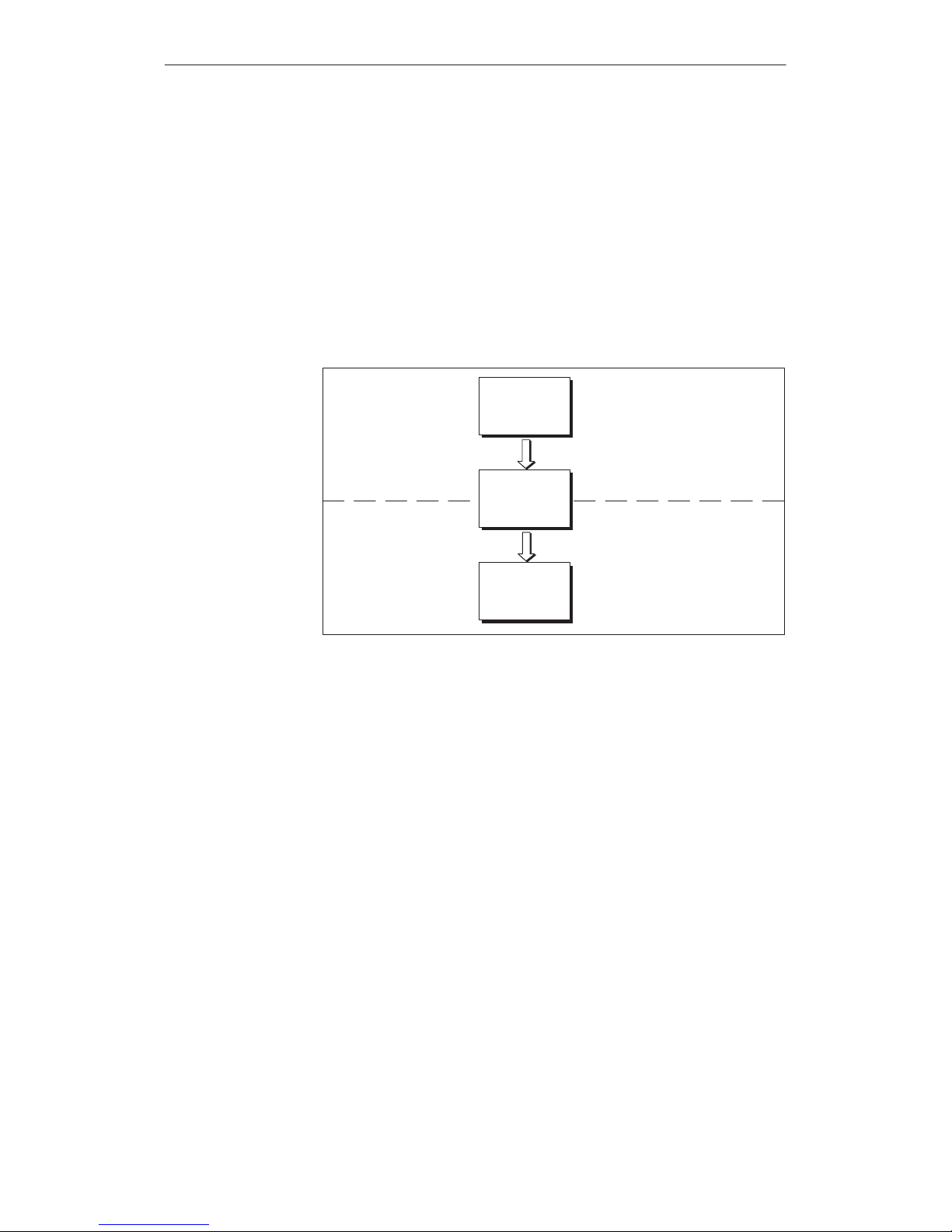
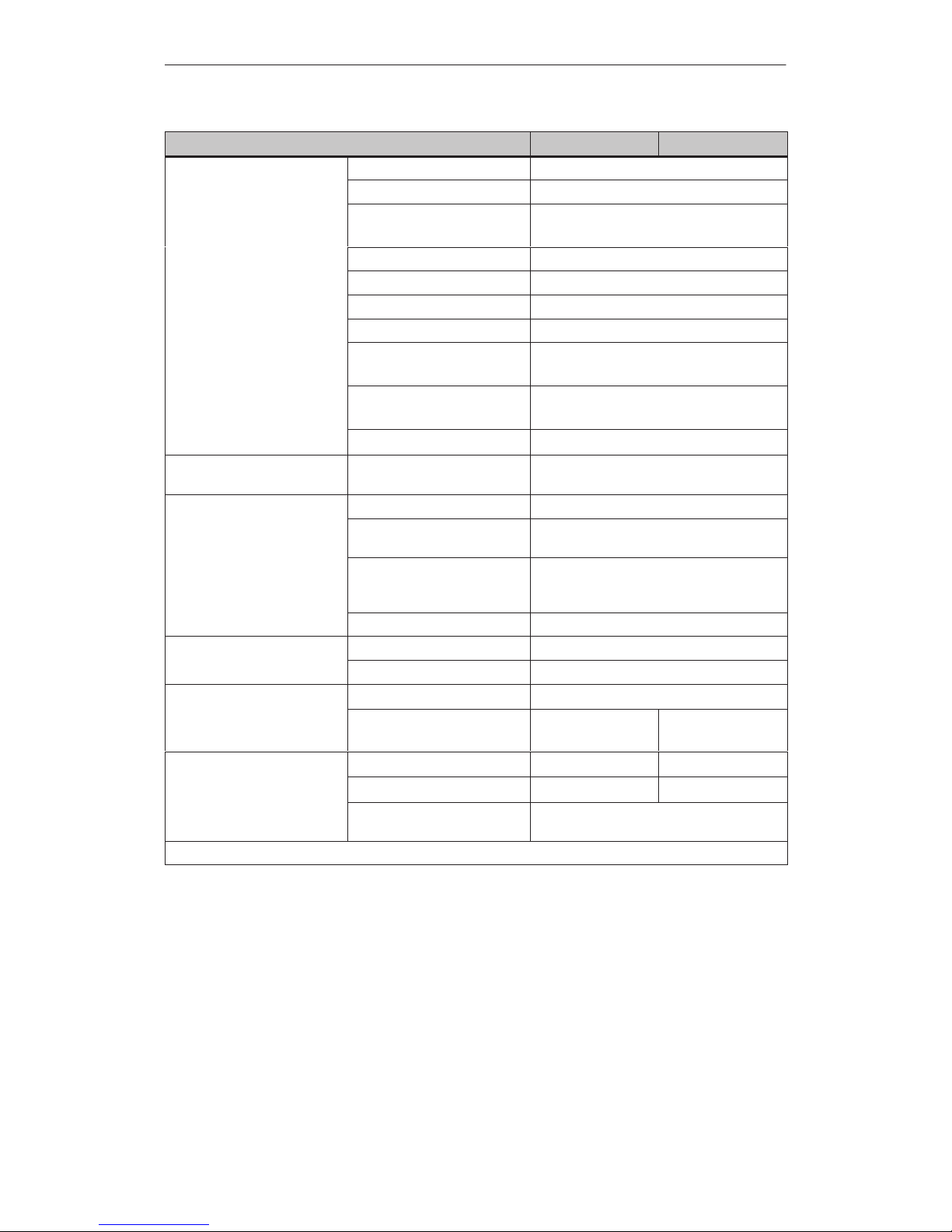
Graphics
and texts to be displayed on the OP must be created beforehand using
a configuration computer (PC or PU) implementing the configuration software
ProT
ool. Before downloading the configuration data to the OP
, connect the
configuration computer to the OP (refer to the configuration phase in Fig
-
ure 1-1).
Once the configuration has been successfully downloaded, disconnect the con
-
figuration computer and then connect the OP to the PLC. The OP now commu
-
nicates with the PLC and reacts to program execution on the PLC in accor
dance with the configured requirements (refer to the process control phase in
Figure 1-1).
Figure 1-1 outlines the configuration and process control phase.
Figure 1-1 Configuration and process control phase
Information
regarding configuration of the OP is provided in the
User’
s Guide,
ProT
ool Configuring Graphics Displays
. The
Communication User’s Manual
provides information on the connection between the OP and PLC.
Configuration
using
ProT
ool
Further
information
Product Description
Artisan Technology Group - Quality Instrumentation ... Guaranteed | (888) 88-SOURCE | www.artisantg.com

1-3
OP27,
OP37 Equipment Manual
Release 05/99
1.1 Visualizing and Controlling Processes
The
basic functions of the OP27 und OP37 Operator Panels are the visualiza
tion of process statuses and the operation of processes. The following display
and operating functions can be configured:
screens
input/output of process values
bar graphs and trends
text or graphics lists
messages
logging
print
text
help text
recipes
multiple languages
password protection
functions for function keys and soft keys.
Logically related process data from the PLC can be compiled, displayed on a
screen and individual parts of it modified. Screens may contain soft keys,
graphics, texts and values.
The OPs can display machines and systems as
full–graphics scr
eens
. This
makes it easier for the operator to find his way around.
Numeric, alphanumeric or symbolic values can be entered in input fields on the
OP which are then transferred to the PLC. Current values of the PLC are dis
played in output fields in alphanumeric form.
Current process values can be output as numeric values, symbolic text,
symbolic graphs or in the form of bar graphs and trend curves.
Bar graphs
represent a value as a rectangular area. Bar graphs can be used to display
fill levels or quantities, for example.
Trends
display a value continuously. This display mode is useful when displaying
values that vary with time, variations in temperature or pressure, for exam
-
ple.
V
arious graphic elements (bitmaps) or texts can be called into the display
depending on the process status. In this way
, for example, the current setting of
a valve can be visualized on the OP screen by means of symbolic graphics, or
text can be modified according to the situation.
Display and
operating
functions
Screens
Input / Output
Bar graphs and
trend curves
Symbol lists
Product Description
Artisan Technology Group - Quality Instrumentation ... Guaranteed | (888) 88-SOURCE | www.artisantg.com

1-4
OP27,
OP37 Equipment Manual
Release 05/99
Messages
are displayed on the OP in plain text. The message text may also
contain current process values. Incoming messages are stored in a message
buf
fer together with their date and time.
Event messages
provide information and operating notes on current processes or machine
states, for example
Motor running at 3000 revs.
Alarm
messages
provide information on critical machine states, for example
Motor speed too high.
Alarm
messages must be acknowledged on account of their ur
gency.
Messages are classified as event messages or alarm messages during configura
-
tion.
All message events can be additionally recorded by being printed out in online
mode on a connected printer
. Messages which have accumulated in the event
and alarm buf
fers can also be printed out.
It is possible to print the current status of a screen by pressing
PRINT SCREEN. It
is possible to configure a function which enables up to 20 screens to be printed
simultaneously.
T
exts identify individual parts of the screen in order to be able to assign the
fields displayed to the process.
Help texts represent additional information and notes for the operator which
can be configured in respect of the screens, input fields and messages. The help
text relating to an alarm message may display information on the cause of a
malfunction and how to clear it.
Complete machine data records can be stored as recipes in the OP
. A recipe
defines the data structure in a configuration. Data is assigned to the configured
structure on the OP
.
The purpose of recipes is to transfer several items of data collectively to the
PLC. In this respect, it is immaterial whether actual recipes, specifications of
quantities, distances to be traversed or temperature variations are involved.
Message texts, texts in screens, help texts and system messages can be stored
in three languages simultaneously in the OP and selected online.
The password protection feature prevents unauthorized operation of the OP
.
Dif
ferent passwords can be assigned to dif
ferent users or user groups, thus
authorizing or prohibiting access to specific control functions by assigning
dif
ferent password levels.
Messages
Recording
Print
Texts
Help texts
Recipe
Multiple languages
Password
protection
Product Description
Artisan Technology Group - Quality Instrumentation ... Guaranteed | (888) 88-SOURCE | www.artisantg.com

1-5
OP27,
OP37 Equipment Manual
Release 05/99
The
OPs are equipped with a range of function keys which can be assigned
operating functions, such as message logging on/of
f, screen selection and print
screen during configuration. The function keys may be assigned globally or
locally
. Globally means that the assignment applies to the whole configuration.
Locally means that the assignment applies only to a single screen. A function
key whose assignment changes from one screen entry to another is known as a
soft key
.
Functions
for
function keys and
soft keys
Product Description
Artisan Technology Group - Quality Instrumentation ... Guaranteed | (888) 88-SOURCE | www.artisantg.com
1-6
OP27,
OP37 Equipment Manual
Release 05/99
1.2 The
OPs at a Glance
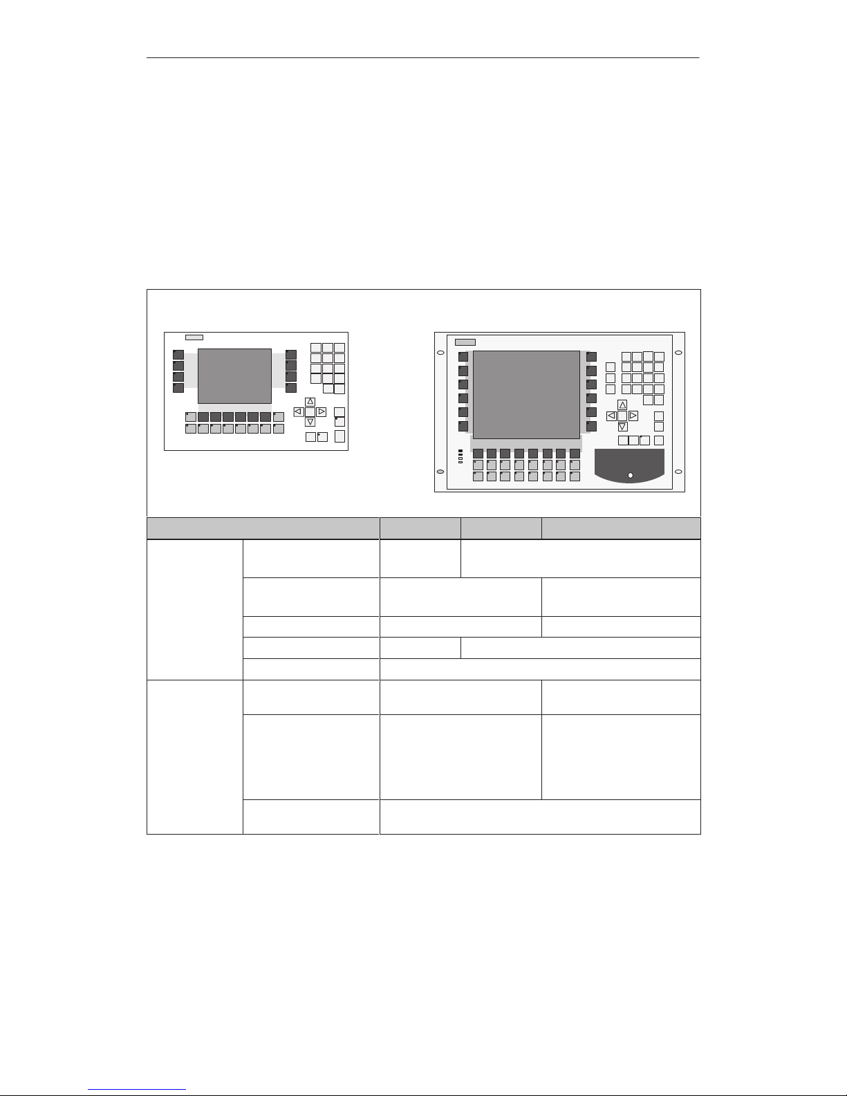
The
following unit models are available:
OP27M with STN monochrome display for screens with gray shading
OP27C with STN color display
OP37 with STN color display
OP37 with TFT color display
OP37
OP27
Hardware OP27M OP27C OP37
Display
Monochrome display
Color display
4
–
–
4
Type STN LCD STN LCD
TFT LCD
Resolution (pixels) 320 x 240 640 x 480
Colors 8 gray scales 8
Backlighting 4
Membrane
keyboard
System keys with permanent functions
24
(4 with LEDs)
32
(4 with LEDs)
Function keys with configurable functions (can
also be used as DP direct
keys)
24
(18 with LEDs)
36
(28 with LEDs)
For use as soft keys 14 20
Key labeling
for function keys
System-specific labeling using labeling strips
Product
Description
Artisan Technology Group - Quality Instrumentation ... Guaranteed | (888) 88-SOURCE | www.artisantg.com
1-7
OP27,
OP37 Equipment Manual
Release 05/99
OP37OP27COP27MHardware
Interfaces
Serial communications
port for
connection to PLC,
PC/PU, printer
2 x RS232/TTY
(active/passive)
1 x RS422/RS485
2 x RS232/TTY
(active/passive)
1 x RS422/RS485
1 x TTY (passive) /
RS422/RS485
Parallel interface for
connecting a printer
– 1 x TTL
(Centronics)
Processor
Type 80486 Pentium
Clock rate (MHz) 33 100
Memory
Flash EPROM for firmware and user data (MB)
1 2
DRAM main memory
(MB)
2 4 8
Buffered SRAM (KB) 128
Hardware OP27M OP27C OP37
Special features
Hardware clock (battery–
backed)
4
Relay output for temperature monitoring
– 4
Use of an external
MF2 keyboard
– 4
1)
Use of an external PS2
keyboard
– 4
1)
Use of an external PS2
mouse
– 4
2)
DOS mode – 4
Module slot for PCMCIA/
JEIDA cards
1 2
(Slot A and Slot B)
3)
1)
Can only be used for BIOS setup and in DOS mode
2)
Can only be used in DOS mode
3)
Slot A can only be used for DOS mode, Slot B for OP and DOS modes
Options OP27M OP27C OP37
Direct key
module
Digital outputs, triggered
optionally by means of
direct keys
configurable outputs
8
8
12
16
Control Panel
Interface
4)
Digital inputs/outputs 16 or 32
Product
Description
Artisan Technology Group - Quality Instrumentation ... Guaranteed | (888) 88-SOURCE | www.artisantg.com

1-8
OP27,
OP37 Equipment Manual
Release 05/99
OP37OP27COP27MOptions
Floppy disk
drive
Storage capacity – 1.44 MB
Hard disk
5)
Storage capacity – 2 GB
AT extension
slot
5)
Plug-in 2/3 length, 16-bit
AT cards
– 2
4)
Can only be used in conjunction with SIMA
TIC S7 PLC
5)
Can only be used in DOS mode
Product
Description
Artisan Technology Group - Quality Instrumentation ... Guaranteed | (888) 88-SOURCE | www.artisantg.com
2-1
OP27,
OP37 Equipment Manual
Release 05/99
Functionalty
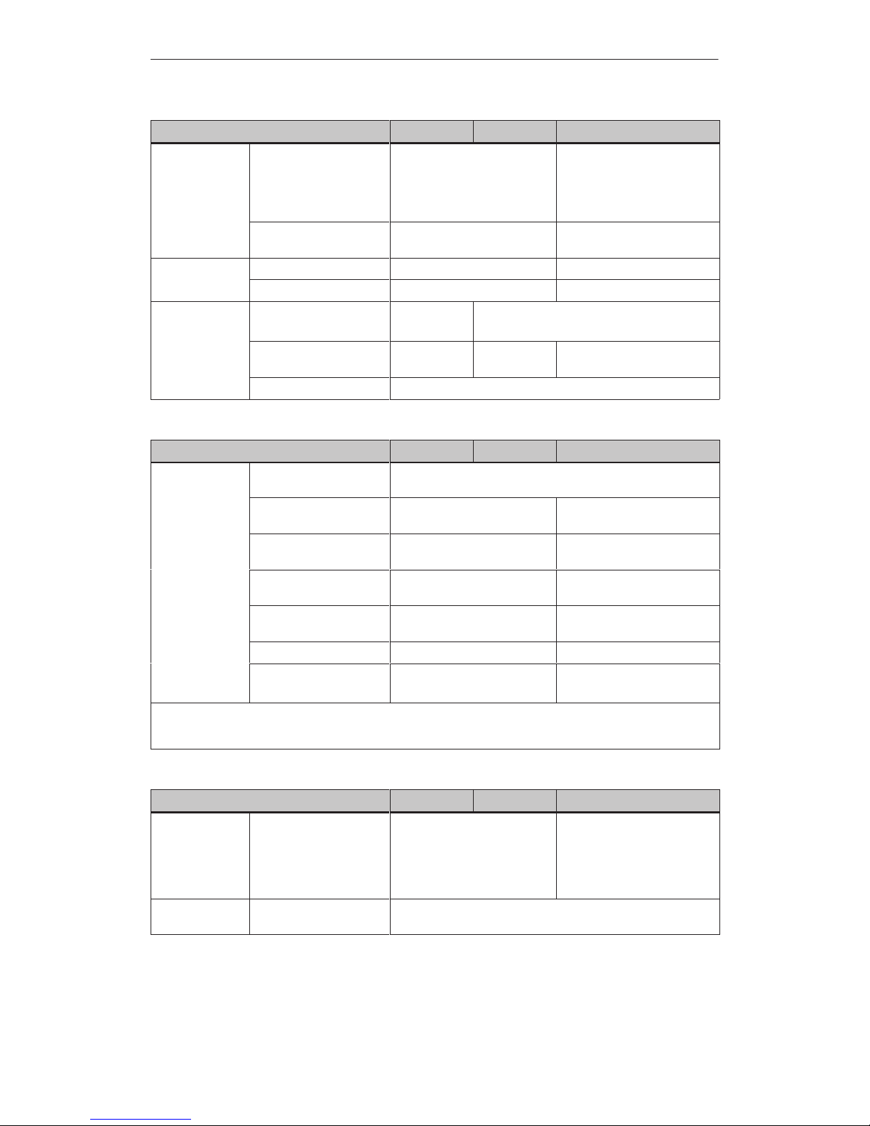
The
following table presents an overview of the functions of operator panels OP27 and OP37. The values
specified are the maximum values that can be managed by the respective OP
. The values are limited by
the size of the working memory
.
Functions OP27 OP37
Event messages
Number 2000
Display in message line/message window
View all pending messages in message page
Length message text per line 35 characters 70 characters
Lines per message 2 1
Process values in message text 8
Alarm
messages
Number 2000
Display in message line/message window
Display type First value/last value, selectable
View all pending messages in message page
Length message text per line 35 characters 70 characters
Lines per message 2 1
Process values in message text 8
Acknowledge individual alarm
messages
4
Acknowledge several alarm
messages simultaneously
16 acknowledgment groups
Message
logging
Output to printer
4
Message
ar
chive
Capacity 512 message events
View buffered event/alarm
messages
4
Delete
4
Buffer overflow warning
4
Automatic printout on buffer
overflow
4
Message events queued
simultaneously (max.)
Event
messages
or
Alarm messages
500
250
2
Artisan Technology Group - Quality Instrumentation ... Guaranteed | (888) 88-SOURCE | www.artisantg.com

2-2
OP27,
OP37 Equipment Manual
Release 05/99
OP37OP27Functions
Message
acquisition
Time of occurrence Date and time
Message events Arrive, depart, acknowledge
Screens
View
4
Printout
4
Static screen elements Pixel graphics
Text
Character graphics
Input/output elements Numeric/alphanumeric input fields
Numeric/alphanumeric output fields
Combined input/output fields
Symbolic text input fields
Symbolic text/graphics output fields
Bar graphs
Trends
Operator prompting Icons for soft key functions
Fixed window
4
Limit
value monitoring
Inputs/outputs
4
Conversion functions
Inputs/outputs
4
T
ext attributes
Display Flashing, inverse, underscore
Printer (messages) Bold, italic, underscore
Help
text
Lines/characters 7/35
For messages
4
For input fields
4
For screens
4
Print
functions
Hardcopy of screen contents
(screen dump)
character mode (ASCII)
graphics mode
4
4
Direct message logging
4
Print screen lists in
character mode
(ASCII)
graphics mode
4
4
Password
pr
otection Number of passwords
Password levels
50
10 (0...9)
Functionalty
Artisan Technology Group - Quality Instrumentation ... Guaranteed | (888) 88-SOURCE | www.artisantg.com
2-3
OP27,
OP37 Equipment Manual
Release 05/99
OP37OP27Functions
Recipes
Number 255
Data records per recipe 500
Entries per data record 500
3000 (SIMATIC S7)
Save (create) data records PLC/OP ! data medium
Load data records Data medium ! OP/PLC
Delete data records On data medium
Modify (edit) data records On data medium
Transfer current values PLC ! OP
OP ! PLC
Transfer data records Data medium ! OP
OP ! Data medium
Record sets
4
Backup Backup/Restore for memory
card
4
Online
language change
Number of languages 3
Loadable character sets per
language
3
Language–independent character set (incl. character–graphic
characters)
1
Character size in pixels 8 x 8 to 64 x 64
PU
functions
SIMATIC S5 4
(Status/Contr
ol T
ag)
SIMATIC S7 4
Display
Blank screen
4
Contrast
4 4
(C-STN display only)
DP direct keys
1)
Number of input
24 36
Number of outputs (LEDs)
18 28
Inputs/outputs with Control
Panel Interface upgradeable by
16 or 32
1)
= Configuration, refer to Communication User’
s Manual
Functionalty
Artisan Technology Group - Quality Instrumentation ... Guaranteed | (888) 88-SOURCE | www.artisantg.com

2-4
OP27,
OP37 Equipment Manual
Release 05/99
OP37OP27Functions
Communication SIMATIC S5
– AS511 4
–FAP 4
– PROFIBUS-DP 4
SIMATIC S7/M7
– PPI
(S7 driver)
4
–
MPI (S7 driver)
–
-
4
–
PROFIBUS-DP
(S7 driver)
4
SIMATIC 500/505
– NITP 4
Block driver
– Free
Serial
4
Loadable NATIVE drivers
(optional)
– AEG/Modicon
(Modbus)
4
–
Allen Bradley (DF1)
4
–
Mitsubishi (FX)
4
– Omron 4
–T
elemecanique
(Adjust, Uni-T
elway)
4
Functionalty
Artisan Technology Group - Quality Instrumentation ... Guaranteed | (888) 88-SOURCE | www.artisantg.com

FUNCTIONS
3 General Operation
4 Screens
5 Password Protection
6 Messages
7 Printing
8 Recipes
9 Storing and Loading Data
10 Status/Control Tag with the OP
11 System Settings
Part
II
Artisan Technology Group - Quality Instrumentation ... Guaranteed | (888) 88-SOURCE | www.artisantg.com

2-2
OP27,
OP37 Equipment Manual
Release 05/99
Artisan Technology Group - Quality Instrumentation ... Guaranteed | (888) 88-SOURCE | www.artisantg.com
3-1
OP27, OP37 Equipment Manual
Release 05/99
General Operation
It
is possible to observe the operating status of the machine or system being
monitored using the OP screen and directly intervene in the process running
via the OP keyboard.
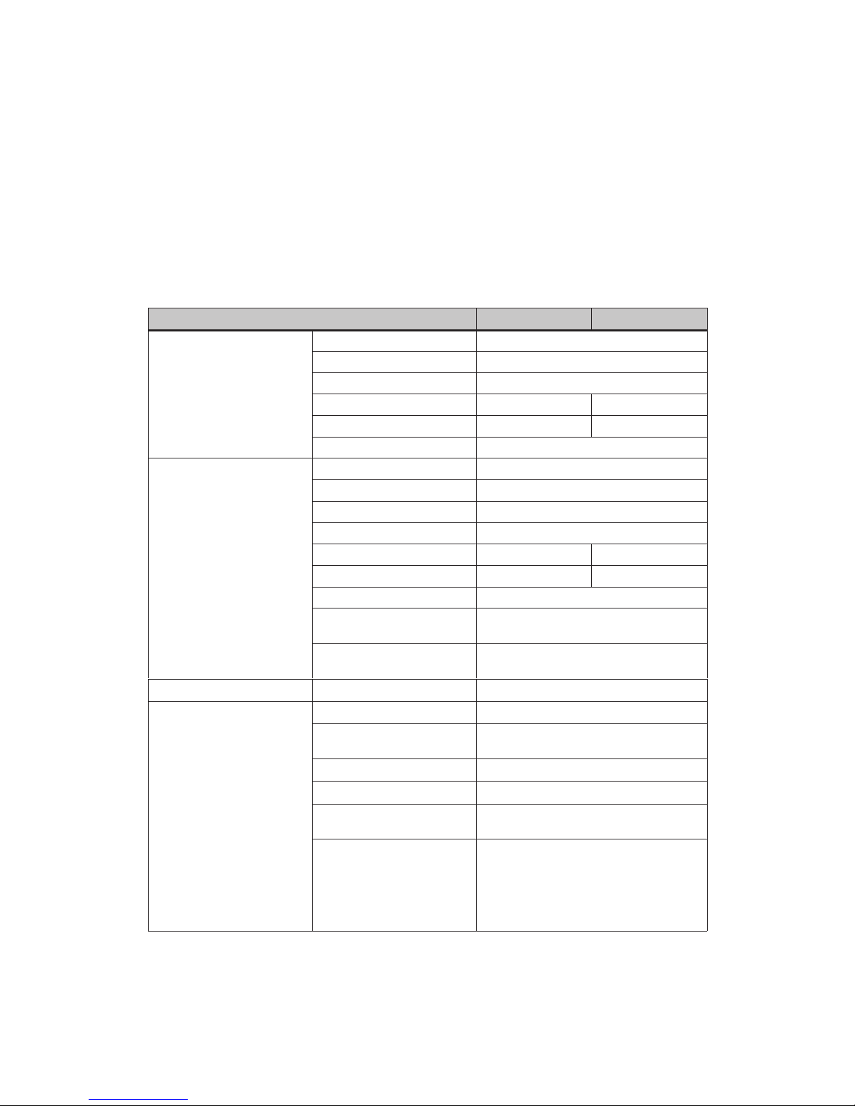
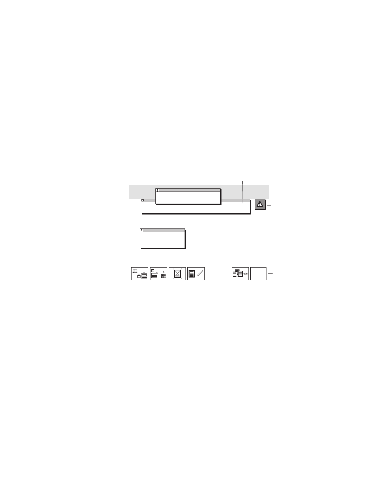
A screen occupies the entire display
. An example of screen partitioning is illus
-
trated in Figure 3-1.
Main
area
Fixed window
ESC
Icons for soft-key
functions
System messages
Event and alarm messages
Message indicators
Help window
Figure 3-1 Screen partitioning on the OP (example OP37)
The
fixed window can be used to display important process magnitudes or date
and time, since the contents are not af
fected by the screen currently open.
The main area comprises the entire display. It is superimposed by all other
areas (fixed window
, message window etc.). The main area contains the current
contents of the screen that is currently open.
Icons are used as symbols of specific screen functions. Icons are located above
or next to soft key function keys in order to describe the functionality of the
key
. The configured function is triggered after pressing the function key
.
Operating concept
Screen partitioning
Fixed window
Main area
Icons
3
Artisan Technology Group - Quality Instrumentation ... Guaranteed | (888) 88-SOURCE | www.artisantg.com
 Loading...