

Siemens SIMATIC HMI KTP700F Mobile, SIMATIC HMI KTP400F Mobile, SIMATIC HMI KTP700 Mobile, SIMATIC HMI KTP900F Mobile, SIMATIC HMI KTP900 Mobile Operating Instructions Manual

___________________
___________________
___________________
___________________
___________________
___________________
___________________
___________________
___________________
___________________
___________________
___________________
___________________
___________________
___________________
SIMATIC HMI
HMI devices
Mobile Panels 2nd Generation
Operating Instructions
09/2018
A5E33876626
Preface
Overview
1
Safety instructions
2
Installing system
components
3
Handling the Mobile Panel
4
Parameterizing the Mobile
Panel
5
Configuring the Mobile Panel
6
Commissioning a project
7
Operating a project
8
Fail-safe operation
9
Maintenance and care
10
Technical specifications
11
Technical Support
A
Markings and symbols
B
List of abbreviations
C
-AC
Siemens AG
Division Digital Factory
Postfach 48 48
90026 NÜRNBERG
GERMANY
A5E33876626-AC
Ⓟ
Copyright © Siemens AG 2018.
All rights reserved
Legal information
Warning notice system
DANGER
indicates that death or severe personal injury will result if proper precautions are not taken.
WARNING
indicates that death or severe personal injury may result if proper precautions are not taken.
CAUTION
indicates that minor personal injury can result if proper precautions are not taken.
NOTICE
indicates that property damage can result if proper precautions are not taken.
Qualified Personnel
personnel qualified
Proper use of Siemens products
WARNING
Siemens products may only be used for the applications described in the catalog and in the relevant technical
ambient conditions must be complied with. The information in the relevant documentation must be observed.
Trademarks
Disclaimer of Liability
This manual contains notices you have to observe in order to ensure your personal safety, as well as to prevent
damage to property. The notices referring to your personal safety are highlighted in the manual by a safety alert
symbol, notices referring only to property damage have no safety alert symbol. These notices shown below are
graded according to the degree of danger.
If more than one degree of danger is present, the warning notice representing the highest degree of danger will
be used. A notice warning of injury to persons with a safety alert symbol may also include a warning relating to
property damage.
The product/system described in this documentation may be operated only by
task in accordance with the relevant documentation, in particular its warning notices and safety instructions.
Qualified personnel are those who, based on their training and experience, are capable of identifying risks and
avoiding potential hazards when working with these products/systems.
Note the following:
documentation. If products and components from other manufacturers are used, these must be recommended
or approved by Siemens. Proper transport, storage, installation, assembly, commissioning, operation and
maintenance are required to ensure that the products operate safely and without any problems. The permissible
All names identified by ® are registered trademarks of Siemens AG. The remaining trademarks in this publication
may be trademarks whose use by third parties for their own purposes could violate the rights of the owner.
We have reviewed the contents of this publication to ensure consistency with the hardware and software
described. Since variance cannot be precluded entirely, we cannot guarantee full consistency. However, the
information in this publication is reviewed regularly and any necessary corrections are included in subsequent
editions.
for the specific
09/2018 Subject to change

Preface
Purpose of the operating instructions
Basic knowledge required
Scope of the document
These operating instructions contain information on place of use, transport, storage,
mounting, use and maintenance of the device.
These operating instructions are intended for:
● Users
● Commissioning engineers
● Maintenance personnel
You can find more information such as operating instructions, examples and reference
information in the information system of the TIA Portal or through online support.
General knowledge of automation technology and process communication is needed to
understand the operating instructions. Knowledge of personal computers and the Microsoft
operating systems is required to understand this manual.
The operating instructions apply to the following Mobile Panels 2nd Generation in
combination with the corresponding connection boxes:
● SIMATIC HMI KTP400F Mobile, article number 6AV2125-2DB23-0AX0
● SIMATIC HMI KTP700 Mobile, article number 6AV2125-2GB03-0AX0
● SIMATIC HMI KTP700F Mobile, article number 6AV2125-2GB23-0AX0
● SIMATIC HMI KTP900 Mobile, article number 6AV2125-2JB03-0AX0
● SIMATIC HMI KTP900F Mobile, article number 6AV2125-2JB23-0AX0
The corresponding connection boxes with article numbers and information on compatibility
can be found in the following sections:
● Connection boxes (Page 18)
● Mobile Panel and connection box compatibility (Page 29)
Mobile Panels 2nd Generation
Operating Instructions, 09/2018, A5E33876626-AC
3

Preface
Note
This document is part of the Mobile Panel system, connecting cable and connection box, and
is also required for repeat commissioning. Keep all supplie
documentation for the entire service life of the Mobile Panel.
Provide any future owner or user with all the documents for the HMI device.
Style conventions
Style Convention
Scope
"File > Edit"
Operational sequences, e.g, menu command, shortcut menu command
<F1>, <Alt+P>
Keyboard operation
Note
A note contains important information abo
handling, or a specific section of the document to which you should pay particular attention.
The document applies in conjunction with the software listed in "Software required
(Page 24)".
d and supplementary
Make sure that every supplement to the documentation that you receive is stored together
with the operating instructions.
"Add screen"
• Terminology that appears in the user interface, for example, dialog
names, tabs, buttons, menu commands
• Necessary entries, for example, limit, tag value
• Path information
Please observe notes labeled as follows:
ut the product described in the document and its
Mobile Panels 2nd Generation
4 Operating Instructions, 09/2018, A5E33876626-AC

Preface
Naming conventions
Term
Applies to
Control cabinet
Mounted cabinet, enclosure, terminal box, panel, control panel
F-system
Fail-safe automation system with fail-safe Mobile Panel
STEP 7
STEP 7 V13 SP1 or higher
Safety optional package
STEP 7 Safety Advanced V13 SP1 or later optional package
Information on standards
Plant System, machining center, one or more machines
Connection box
HMI device
Mobile Panel
Fail-safe Mobile Panel
Safety-related operator
control
Storage medium
WinCC
• Connection box compact
• Connection box standard
• Connection box advanced
• KTP400F Mobile
• KTP700 Mobile
• KTP700F Mobile
• KTP900 Mobile
• KTP900F Mobile
• KTP400F Mobile
• KTP700F Mobile
• KTP900F Mobile
• Emergency stop / stop button
• Enabling button
• SD memory card
• USB flash drive
• WinCC Comfort V13 SP1 or higher
• WinCC Advanced V13 SP1 or higher
You can find detailed information on standards including year of publication and
corresponding supplements in the section "Standards on operating safety (Page 221)".
Standards and supplements will be referenced in the remainder of the document without
citation of the year of publication, for example, "EN 61000-6-4 +A1".
Mobile Panels 2nd Generation
Operating Instructions, 09/2018, A5E33876626-AC
5

Preface
Figures
See also
This document contains figures of the devices described. The figures can deviate from the
particularities of the delivered device.
Picture components are marked with black position numbers on a white background
①, ②, ③, etc.
Steps in the figures are identified with white process numbers on a black background
according to the sequence in which they have to be executed: , , , ...
Terms for fail-safe operation (Page 24)
Mobile Panels 2nd Generation
6 Operating Instructions, 09/2018, A5E33876626-AC

Table of contents
Preface ................................................................................................................................................... 3
1 Overview............................................................................................................................................... 13
2 Safety instructions ................................................................................................................................. 31
3 Installing system components ............................................................................................................... 43
1.1 Product overview .................................................................................................................... 13
1.2 Design of the Mobile Panels ................................................................................................... 14
1.3 KTP Mobile connecting cable ................................................................................................. 17
1.4 Connection boxes ................................................................................................................... 18
1.5 Scope of delivery .................................................................................................................... 20
1.6 Accessories ............................................................................................................................. 21
1.6.1 KTP Mobile wall-mounting bracket ......................................................................................... 21
1.6.2 Fail-safe KTP Mobile spare key .............................................................................................. 22
1.6.3 Protective films ........................................................................................................................ 22
1.6.4 Storage media ......................................................................................................................... 22
1.6.5 SIRIUS safety relays ............................................................................................................... 23
1.7 Software required .................................................................................................................... 24
1.8 Terms for fail-safe operation ................................................................................................... 24
1.9 Organizational measures ........................................................................................................ 28
1.10 Mobile Panel and connection box compatibility ...................................................................... 29
2.1 General safety instructions ..................................................................................................... 31
2.2 Security management for HMI devices ................................................................................... 36
2.3 Data protection ........................................................................................................................ 36
2.4 Notes about usage .................................................................................................................. 37
2.5 Risk assessment of the plant .................................................................................................. 38
2.6 Important information on emergency stop / stop button ......................................................... 39
2.7 Important notes for the enabling mechanism ......................................................................... 40
3.1 Checking the delivery.............................................................................................................. 43
3.2 Mounting the connection box compact ................................................................................... 43
3.2.1 Mounting position, mounting cutout and clearance ................................................................ 43
3.2.2 Fastening the connection box compact .................................................................................. 45
3.3 Installing the connection box standard and connection box advanced .................................. 45
3.3.1 Mounting position and clearance ............................................................................................ 45
3.3.2 Fastening the connection box standard and connection box advanced ................................. 46
Mobile Panels 2nd Generation
Operating Instructions, 09/2018, A5E33876626-AC
7

Table of contents
4 Handling the Mobile Panel .................................................................................................................... 77
5 Parameterizing the Mobile Panel ........................................................................................................... 87
3.4 Attaching the KTP Mobile wall-mounting bracket .................................................................. 47
3.4.1 Assembling the KTP Mobile wall-mounting bracket ............................................................... 47
3.4.2 Mounting position and clearance ........................................................................................... 48
3.4.3 Fasteneing the KTP Mobile wall-mounting bracket ............................................................... 50
3.5 Connecting the Mobile Panel ................................................................................................. 51
3.5.1 Connection information .......................................................................................................... 51
3.5.2 Inserting the SD memory card ............................................................................................... 51
3.5.3 Connecting the Mobile Panel connecting cable ..................................................................... 53
3.5.4 Connecting a Configuring PC ................................................................................................ 54
3.5.5 Replacing the connecting cable ............................................................................................. 55
3.5.6 Replacing an SD memory card .............................................................................................. 57
3.5.7 Inserting the USB memory stick ............................................................................................. 58
3.6 Connecting the connection box .............................................................................................. 59
3.6.1 Connection information .......................................................................................................... 59
3.6.2 Opening and closing connection box standard and connection box advanced ..................... 60
3.6.3 Equipotential bonding of connection boxes ........................................................................... 62
3.6.4 Connecting the functional grounding and power supply to the connection box .................... 64
3.6.5 Connecting cables for a hardwired F-system ........................................................................ 66
3.6.6 Connecting Ethernet to the connection box ........................................................................... 67
3.6.7 Setting the box ID of the connection box ............................................................................... 70
3.6.8 Secure cables and seal screw glands ................................................................................... 72
3.7 Connecting the KTP Mobile connecting cable to the connection box.................................... 73
3.8 Selecting the connection box ................................................................................................. 75
4.1 Holding the Mobile Panel and attaching it to the wall-mounting bracket ............................... 77
4.2 Keyswitches, function keys and illuminated pushbuttons ...................................................... 79
4.3 Operating the enabling button ................................................................................................ 81
4.4 Pressing the emergency stop / stop button ........................................................................... 83
4.5 Testing Mobile Panel readiness for operation ....................................................................... 85
5.1 Firmware and software .......................................................................................................... 87
5.2 Desktop and Start Center ...................................................................................................... 87
5.3 Operating the desktop, Start Center and Control Panel ........................................................ 88
5.4 Installed programs ................................................................................................................. 88
5.5 Security mode ........................................................................................................................ 89
5.5.1 Overview ................................................................................................................................ 89
5.5.2 Using the HMI device in password-protected security mode ................................................. 89
5.6 Control Panel ......................................................................................................................... 90
5.6.1 Opening the settings .............................................................................................................. 90
5.6.2 Overview of functions ............................................................................................................. 91
5.6.3 Operating the Control Panel .................................................................................................. 93
5.6.4 Display types for the screen keyboard ................................................................................... 93
Mobile Panels 2nd Generation
8 Operating Instructions, 09/2018, A5E33876626-AC

Table of contents
5.7 Configuring operation.............................................................................................................. 96
5.7.1 Changing display brightness ................................................................................................... 96
5.7.2 Configuring the screen keyboard ............................................................................................ 97
5.7.3 Setting the character repeat rate of the screen keyboard ...................................................... 98
5.7.4 Setting the double-click ........................................................................................................... 99
5.7.5 Calibrating the touch screen ................................................................................................. 100
5.7.6 Restarting the HMI device .................................................................................................... 101
5.8 General settings .................................................................................................................... 103
5.8.1 Regional and language settings ........................................................................................... 103
5.8.2 Setting the date and time ...................................................................................................... 104
5.8.3 Entering and deleting a password ........................................................................................ 105
5.8.4 Setting the screen saver ....................................................................................................... 107
5.8.5 Parameterizing Transfer ....................................................................................................... 109
5.8.6 Storage management ........................................................................................................... 111
5.8.6.1 Displaying the memory distribution ....................................................................................... 111
5.8.6.2 Setting the project storage location and start delay .............................................................. 111
5.8.6.3 Activating memory management .......................................................................................... 113
5.8.6.4 Activate/deactivate retentivity of the alarm buffer on the HMI device ................................... 113
5.8.7 Backing up registry information and temporary data ............................................................ 115
5.8.8 Changing the print options .................................................................................................... 116
5.8.9 Displaying general system properties ................................................................................... 117
5.8.10 Displaying information about the Mobile Panel .................................................................... 118
5.8.11 Display firmware ................................................................................................................... 118
5.9 Changing Internet settings ....................................................................................................
119
5.9.1 Changing general settings .................................................................................................... 119
5.9.2 Setting the proxy server ........................................................................................................ 120
5.9.3 Changing Internet security settings ...................................................................................... 121
5.9.4 Activating encryption protocols ............................................................................................. 123
5.9.5 Importing, displaying and deleting certificates ...................................................................... 124
5.10 Enabling PROFINET ............................................................................................................. 126
5.11 Enabling NTP ........................................................................................................................ 127
5.12 Setting the PROFIsafe address ............................................................................................ 129
5.13 Configuring network operation .............................................................................................. 130
5.13.1 Overview ............................................................................................................................... 130
5.13.2 Specifying the computer name of the HMI device ................................................................ 131
5.13.3 Specifying the IP address and name server ......................................................................... 132
5.13.4 Specifying the logon data ..................................................................................................... 133
5.13.5 Configuring e-mail ................................................................................................................. 134
5.13.6 Configuring Telnet for remote control ................................................................................... 136
5.13.7 Configure Sm@rt Server ...................................................................................................... 136
5.13.8 Configure Web Server .......................................................................................................... 140
5.14 Assigning a safety-related operating mode .......................................................................... 142
5.15 Functions for service and commissioning ............................................................................. 144
5.15.1 Saving to external storage medium – backup ....................................................................... 144
5.15.2 Restoring from external storage medium – Restore ............................................................. 147
5.15.3 Update operating system ...................................................................................................... 149
5.15.4 Load project from external storage medium ......................................................................... 152
5.15.5 Using automatic backup........................................................................................................
155
Mobile Panels 2nd Generation
Operating Instructions, 09/2018, A5E33876626-AC
9

Table of contents
6 Configuring the Mobile Panel ............................................................................................................... 165
7 Commissioning a project ...................................................................................................................... 189
8 Operating a project .............................................................................................................................. 203
5.15.6 Editing IP addresses and communication connections ....................................................... 159
5.15.6.1 Overview .............................................................................................................................. 159
5.15.6.2 Assigning IP address and device name ............................................................................... 160
5.15.6.3 Configuring a communication connection ............................................................................ 162
6.1 Configuration in WinCC ....................................................................................................... 167
6.1.1 Adding a controller to the project ......................................................................................... 167
6.1.2 Adding the Mobile Panel to the project ................................................................................ 169
6.1.3 Configuring a fail-safe Mobile Panel .................................................................................... 170
6.2 Configuring F-FBs in STEP 7 ............................................................................................... 174
6.3 Configuring plant areas in WinCC........................................................................................ 179
6.3.1 Overview .............................................................................................................................. 179
6.3.2 Configuring connection point detection ................................................................................ 179
6.3.3 Configuring zones and start screens ................................................................................... 181
6.4 Additional configuration options in WinCC ........................................................................... 182
6.4.1 Configuring function and direct keys .................................................................................... 182
6.4.2 Setting the transfer mode ..................................................................................................... 183
6.4.3 Changing the operating mode .............................................................................................. 183
6.5 Controlling and evaluating operator controls and display elements .................................... 184
6.5.1 Overview .............................................................................................................................. 184
6.5.2 Evaluating operator controls as direct keys ......................................................................... 184
6.5.3 Controlling the LEDs of the function keys by means of system functions ........................... 187
6.5.4 Controlling and evaluating the illuminated pushbutton by means of system functions ....... 187
6.5.5 Evaluating the key-operated switch by means of system functions .................................... 188
7.1 Overview .............................................................................................................................. 189
7.2 Using existing projects ......................................................................................................... 190
7.3 Data Transmission Options .................................................................................................. 190
7.4 Transferring a project with WinCC ....................................................................................... 191
7.4.1 Configuring data channel and setting transfer mode ........................................................... 191
7.4.2 Starting the transfer ............................................................................................................. 191
7.4.3 Testing a project................................................................................................................... 193
7.5 Backup and restore .............................................................................................................. 194
7.5.1 Backup and restore with a PC ............................................................................................. 194
7.5.2 Backup and restore with an external storage medium......................................................... 194
7.5.3 Backup and restore via ProSave ......................................................................................... 194
7.6 Updating the operating system using ProSave .................................................................... 196
7.7 Reset to factory settings with ProSave ................................................................................ 198
7.8 Managing WinCC options .................................................................................................... 200
7.9 Transferring a license key .................................................................................................... 201
8.1 Overview .............................................................................................................................. 203
8.2 Function keys ....................................................................................................................... 204
Mobile Panels 2nd Generation
10 Operating Instructions, 09/2018, A5E33876626-AC

Table of contents
9 Fail-safe operation .............................................................................................................................. 209
10 Maintenance and care ......................................................................................................................... 215
11 Technical specifications ...................................................................................................................... 219
8.3 Direct keys ............................................................................................................................ 205
8.4 Setting the project language ................................................................................................. 205
8.5 Entering and modifying the value, date and time ................................................................. 206
8.6 Displaying infotext ................................................................................................................. 207
8.7 Closing the project ................................................................................................................ 208
9.1 Connecting the connecting cable .......................................................................................... 209
9.2 Unplugging the connecting cable .......................................................................................... 211
9.3 Safety-related dialogs ........................................................................................................... 212
9.3.1 "End PROFIsafe communication" dialog .............................................................................. 212
9.3.2 "Confirm communication error" dialog .................................................................................. 213
9.3.3 "Fatal Error" dialog ................................................................................................................ 213
10.1 General information on maintenance and servicing ............................................................. 215
10.2 Replacing the Mobile Panel .................................................................................................. 215
10.3 Servicing the Mobile Panel ................................................................................................... 216
10.4 Cleaning the Mobile Panel .................................................................................................... 217
10.5 Spare parts and repairs ........................................................................................................ 218
10.6 Recycling and disposal ......................................................................................................... 218
11.1 Software license agreements ............................................................................................... 219
11.2 Certificates and approvals .................................................................................................... 219
11.3 Standards on operating safety .............................................................................................. 221
11.4 Electromagnetic compatibility ............................................................................................... 221
11.5 Mechanical ambient conditions ............................................................................................. 223
11.5.1 Storage conditions ................................................................................................................ 223
11.5.2 Operating Conditions ............................................................................................................ 223
11.6 Climatic ambient conditions .................................................................................................. 224
11.6.1 Long-term storage ................................................................................................................. 224
11.6.2 Transport and short-term storage ......................................................................................... 224
11.6.3 Operating Conditions ............................................................................................................ 224
11.7 Dimension drawings .............................................................................................................. 225
11.7.1 KTP400F Mobile dimension drawing .................................................................................... 225
11.7.2 KTP700 Mobile dimension drawing ...................................................................................... 226
11.7.3 KTP700F Mobile dimension drawing .................................................................................... 227
11.7.4 KTP900 Mobile dimension drawing ...................................................................................... 228
11.7.5 KTP900F Mobile dimension drawing .................................................................................... 229
11.7.6 Connection box compact dimension drawing ....................................................................... 230
11.7.7 Dimension drawing for connection box standard and connection box advanced ................ 231
11.7.8 KTP Mobile wall-mounting bracket dimension drawing ........................................................ 232
Mobile Panels 2nd Generation
Operating Instructions, 09/2018, A5E33876626-AC
11

Table of contents
A Technical Support ................................................................................................................................ 267
B Markings and symbols ......................................................................................................................... 271
C List of abbreviations ............................................................................................................................. 273
Glossary .............................................................................................................................................. 275
Index ................................................................................................................................................... 281
11.8 Technical specifications ....................................................................................................... 233
11.8.1 Mobile Panel ........................................................................................................................ 233
11.8.2 Connecting cable ................................................................................................................. 235
11.8.3 Connection boxes ................................................................................................................ 236
11.8.4 Power consumption specifications ....................................................................................... 238
11.8.5 Reaction times and safety characteristics for fail-safe operation ........................................ 239
11.8.6 Specification of cables to be used ....................................................................................... 242
11.9 Interface description for Mobile Panel ................................................................................. 243
11.9.1 Internal interface X1P1 ........................................................................................................ 243
11.9.2 Internal interface X80 ........................................................................................................... 243
11.9.3 External interface X61 .......................................................................................................... 243
11.10 Connection box compact interfaces ..................................................................................... 244
11.10.1 Position of the interfaces ...................................................................................................... 244
11.10.2 Interface X1 .......................................................................................................................... 244
11.10.3 Plug-in terminal strip X10 ..................................................................................................... 245
11.10.4 Wiring of safety-related operator controls ............................................................................ 246
11.11 Interfaces of the connection box standard and connection box advanced .......................... 248
11.11.1 Position of the interfaces ...................................................................................................... 248
11.11.2 Fast connector X1 and X2 ................................................................................................... 249
11.11.3 Plug-in terminal strip X10 ..................................................................................................... 249
11.11.4 Wiring of safety-related operator controls ............................................................................ 250
11.12 Communication with controllers ........................................................................................... 253
11.13 Scope of functions with WinCC ............................................................................................
254
11.14 Mobile Panel 2nd Generation F-FBs ................................................................................... 258
11.14.1 Using F-FBs ......................................................................................................................... 258
11.14.2 F_FB_KTP_Mobile ............................................................................................................... 260
11.14.3 F_FB_KTP_RNG .................................................................................................................. 263
A.1 Troubleshooting ................................................................................................................... 267
A.2 Service and support ............................................................................................................. 268
A.3 Parameterization of the connection box standard and connection box advanced .............. 269
A.4 System events...................................................................................................................... 269
B.1 Safety-relevant symbols ....................................................................................................... 271
Mobile Panels 2nd Generation
12 Operating Instructions, 09/2018, A5E33876626-AC
1
1.1
Product overview
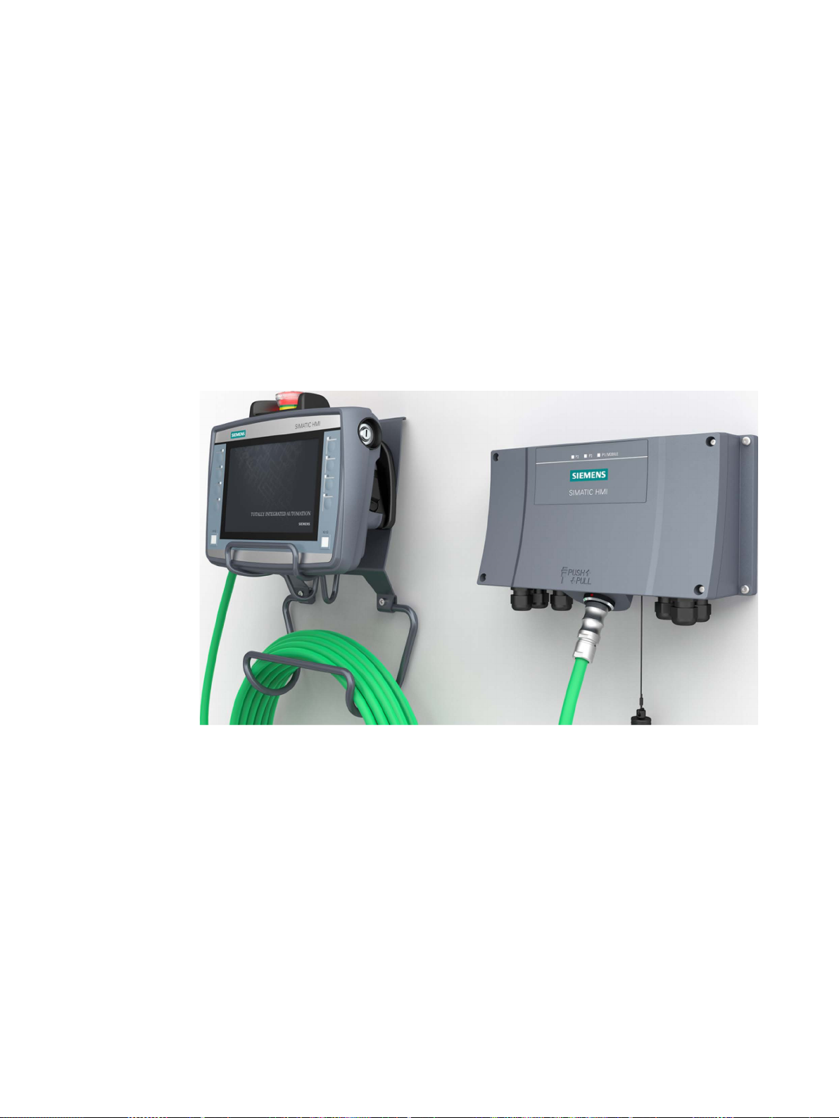
The second generation of SIMATIC HMI Mobile Panels offers direct mobile operation and
monitoring of the production process. The Mobile Panels 2nd Generation system consists of
a Mobile Panel, connection box and connecting cable.
The Mobile Panels 2nd Generation is available with display sizes 4", 7" and 9" widescreen.
The figure below shows a fail-safe Mobile Panel with a 7" widescreen display connected to a
connection box advanced.
Depending on the application, either non-fail-safe or fail-safe Mobile Panels can be used.
With a fail-safe Mobile Panel, you run the plant in fail-safe mode. You meet the requirements
of Safety Integrity Level 3 and Performance Level PL e with a fail-safe Mobile Panel. An
emergency stop / stop switch and an enabling button are integrated in a fail-safe Mobile
Panel 2nd Generation. You can hardwire the safety-related operator controls or evaluate
them in a PROFIsafe-based F-system with a fail-safe controller.
The 7" and 9" devices come equipped with a keyswitch as additional option for protecting the
HMI device from unauthorized access.
You can choose from three connection boxes each with a different range of functions. The
connection box compact is designed for installation in control cabinets. The connection box
standard and connection box advanced are approved for external mounting directly on the
machine.
Mobile Panels 2nd Generation
Operating Instructions, 09/2018, A5E33876626-AC
13

Overview
1.2
Design of the Mobile Panels
SIMATIC HMI
Number of
function keys
Illuminated
pushbutton
Emergency stop / stop button,
acknowledgment button
Keyswitch
KTP400F Mobile
4 2 Yes
No
KTP700F Mobile
8 2 Yes
Yes
KTP900 Mobile
10 2 No
No
KTP900F Mobile
10 2 Yes
Yes
Note
System components
To operate a Mobile Panel, you need:
•
•
•
•
You can find the ordering information for the system components on the Internet
(
1.2 Design of the Mobile Panels
The device is designed for industrial use:
● High fall resistance
● High protection class
● High impact resistance
● High chemical resistance to operating and cleaning agents
(http://support.automation.siemens.com/WW/view/en/39718396
).
The enclosure type protects the emergency stop / stop button. Two protective bumpers to
prevent damage to the emergency stop / stop button during a fall of the HMI device.
All Mobile Panels can be configured with the WinCC software. WinCC is a component of the
"Totally Integrated Automation Portal" engineering framework.
The Mobile Panels 2nd Generation are available in the following device versions:
KTP700 Mobile 8 2 No No
An HMI device
A connecting cable (Page 17)
At least one connection box (Page 18)
For hardwired F-systems: A safety relay (Page 23) or suitable F-DI modules.
https://mall.industry.siemens.com/mall/en/de/Catalog/Products/10165537).
Mobile Panels 2nd Generation
14 Operating Instructions, 09/2018, A5E33876626-AC
Overview
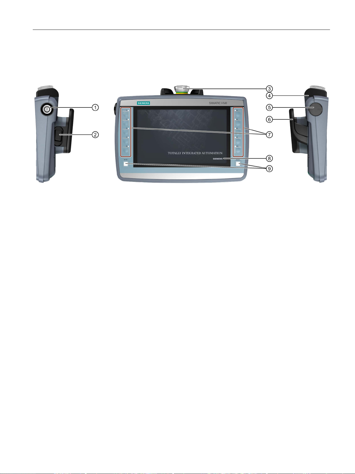
Front and side views
①
Keyswitch, only for KTP700F Mobile and KTP900F Mobile
②
Enabling button, for fail-safe Mobile Panel
③
Emergency stop / stop switch for fail-safe Mobile Panel
④
Drop protection for emergency stop / stop switch for fail-safe Mobile Panel
⑤
Cover of the USB port
⑥
Handle
⑦
Function key blocks
⑧
Display with touch screen
⑨
Illuminated pushbutton
1.2 Design of the Mobile Panels
The figures below show an example of the design of the fail-safe HMI device, KTP900F
Mobile. The other HMI devices of the type KTP Mobile are constructed similarly.
The position of the emergency stop/stop button makes it easily accessible. Due to its profiled
design, the emergency stop/stop button is easily accessible. Two bumpers protect the
emergency stop / stop button against impact damage, for example, if it falls. The bumpers
are dimensioned so that the emergency stop / stop button can be activated during an impact.
The operator controls are described in the section "Handling the Mobile Panel (Page 77)".
Mobile Panels 2nd Generation
Operating Instructions, 09/2018, A5E33876626-AC
15
Overview
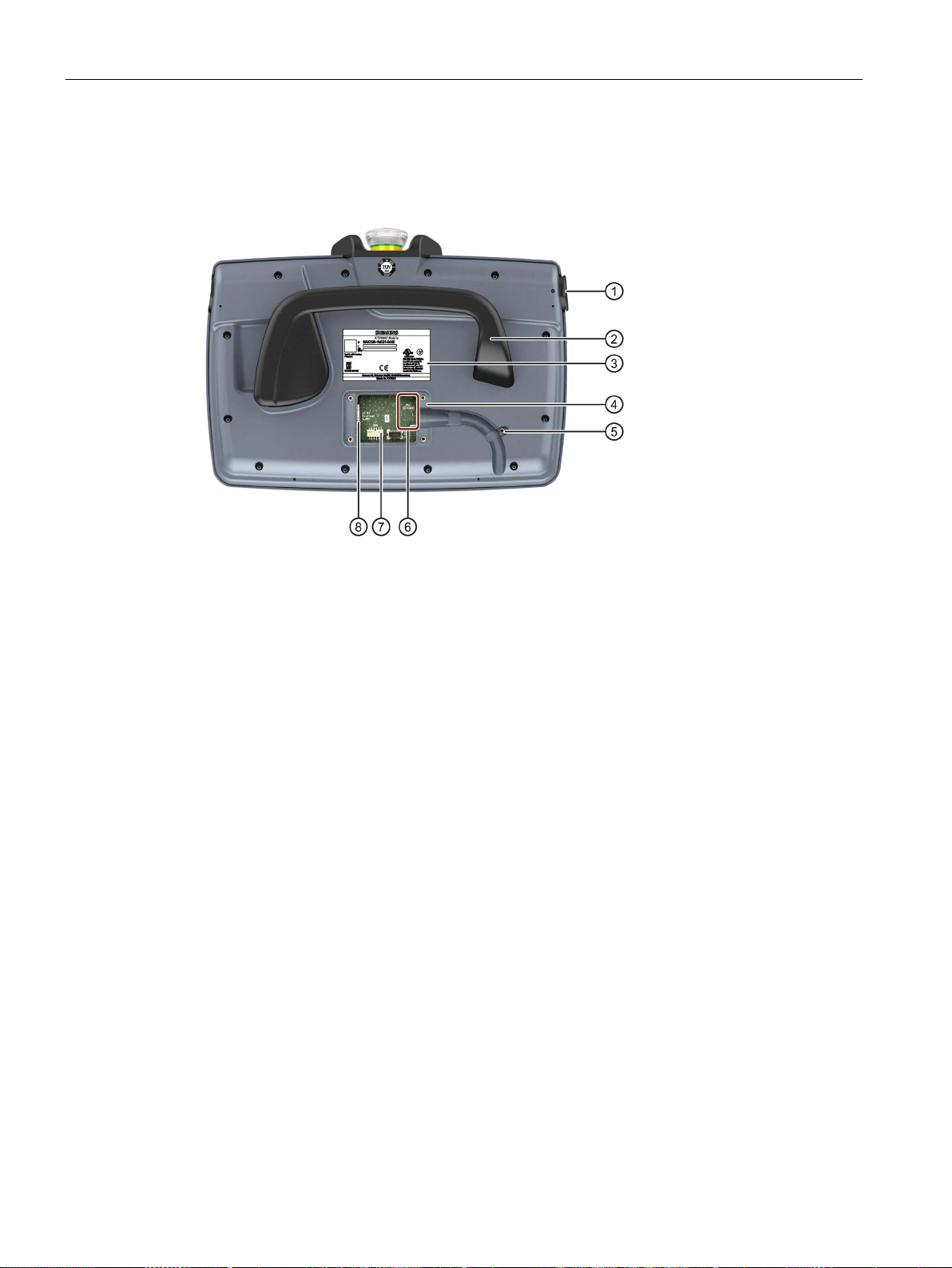
Rear view and interfaces
①
⑤
not for KTP400F Mobile
②
Handle
⑥
Slot for an SD memory card, not for KTP400F Mobile
③
Nameplate
⑦
12-pin connector for the connecting cable
④
Terminal compartment
⑧
RJ45 socket PROFINET (LAN)
1.2 Design of the Mobile Panels
The figure below shows an example of the design of the fail-safe HMI device, KTP900F
Mobile. The other HMI devices of the type KTP Mobile are constructed similarly.
USB port with cover
Threaded sleeve for mounting screw of the cable retainer,
Mobile Panels 2nd Generation
16 Operating Instructions, 09/2018, A5E33876626-AC
Overview
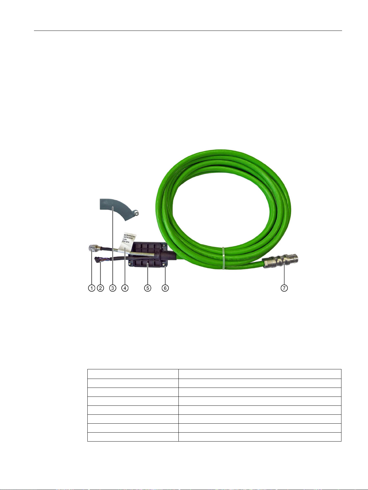
1.3
KTP Mobile connecting cable
①
RJ45 connector
②
Plug connector, 12-pin
③
Retainer, not required for KTP400F Mobile.
④
Label with order number, length specification and product version
⑤
Seal
⑥
Terminal compartment cover
⑦
Connector for the connection box
Product name and length
Article number
KTP Mobile 2 m connecting cable
6AV2181-5AF02-0AX0
KTP Mobile 5 m connecting cable
6AV2181-5AF05-0AX0
KTP Mobile 8 m connecting cable
6AV2181-5AF08-0AX0
KTP Mobile 10 m connecting cable
6AV2181-5AF10-0AX0
KTP Mobile 15 m connecting cable
6AV2181-5AF15-0AX0
KTP Mobile 20 m connecting cable
6AV2181-5AF20-0AX0
KTP Mobile 25m connecting cable
6AV2181-5AF25-0AX0
1.3 KTP Mobile connecting cable
You connect the Mobile Panel to the connection box using the rugged connecting cable. The
tensile and flexural strength of the connecting cable is geared toward the actual usage
conditions.
Functions of the connecting cable:
● Power supply of the Mobile Panel
● Ethernet connection between Mobile Panel and connection box
● Transmission of the signals for emergency stop / stop button and enabling button
● Transmission of the box ID
The KTP Mobile connecting cable is available in the following lengths:
Mobile Panels 2nd Generation
Operating Instructions, 09/2018, A5E33876626-AC
17
Overview
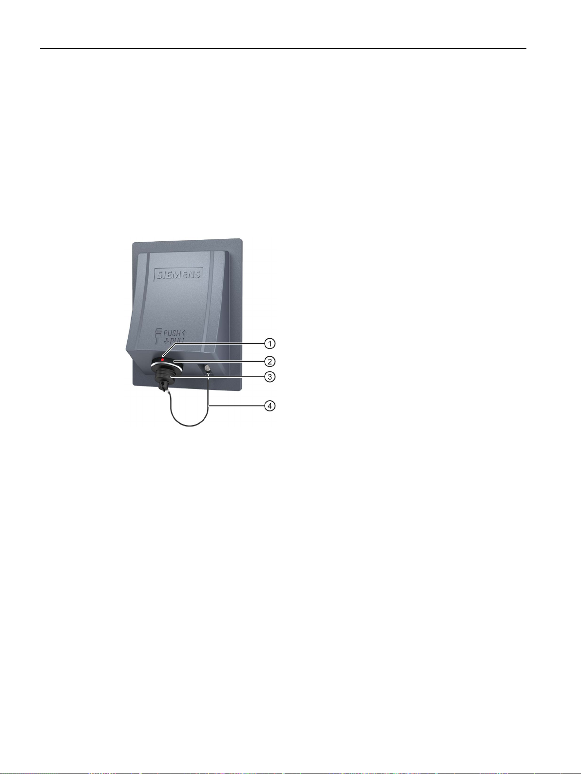
1.4
Connection boxes
Connection box compact
①
positioning mark on the connection box when connecting.
②
Connection socket for the connecting cable
③
Cover of the connection socket
④
Safety strap
1.4 Connection boxes
The connection boxes are available in the following versions:
● Connection box compact, article number 6AV2125-2AE03-0AX0
● Connection box standard, article number 6AV2125-2AE13-0AX0
● Connection box advanced, article number 6AV2125-2AE23-0AX0
The figure below shows the connection box compact.
Positioning mark
There is also a red positioning mark on the connecting cable. Align this mark with the
Mobile Panels 2nd Generation
18 Operating Instructions, 09/2018, A5E33876626-AC
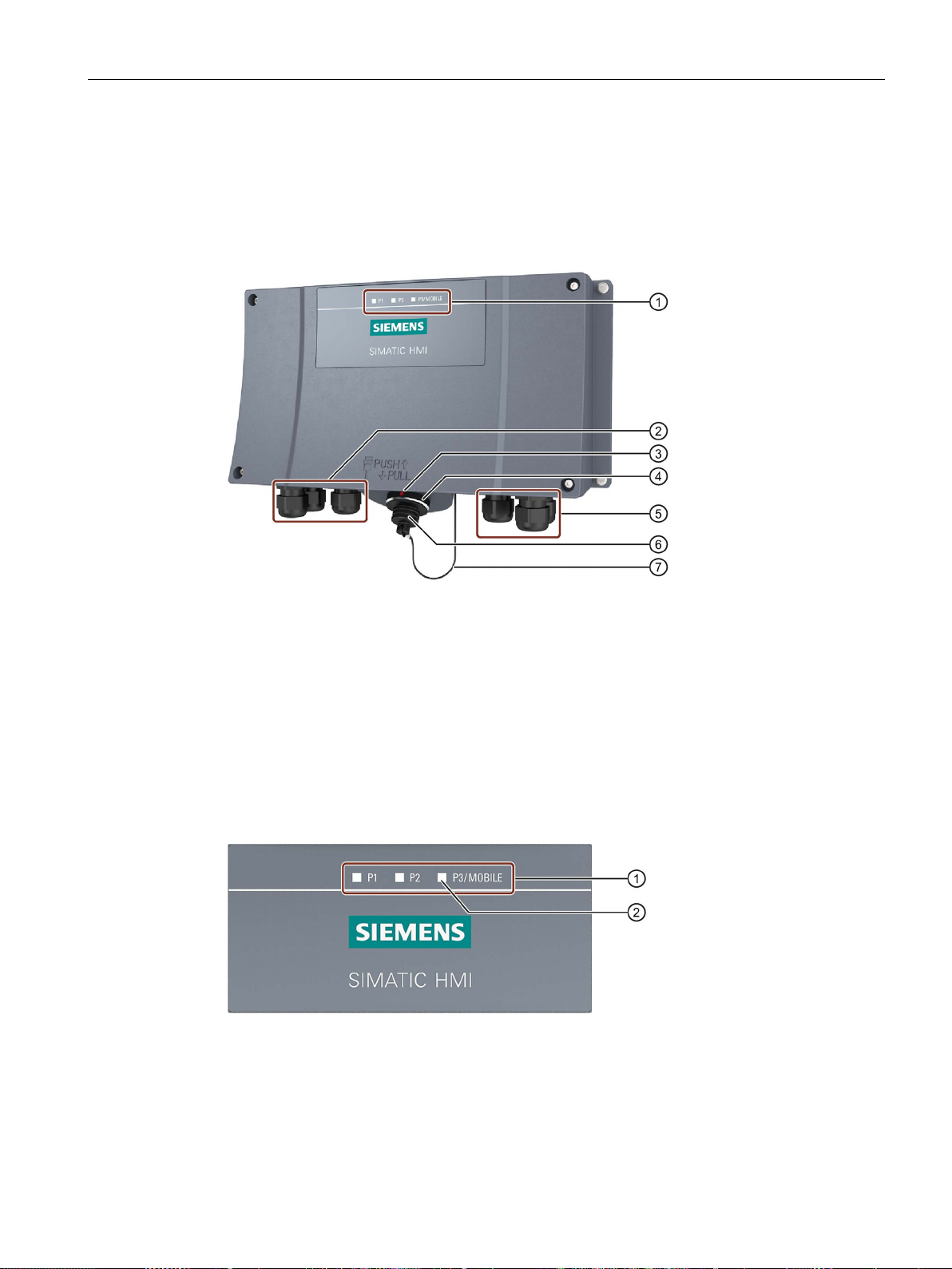
Overview
Connection box standard and connection box advanced
①
LED display
②
Screw glands for the data cables
③
positioning mark on the connection box when connecting.
④
Connection socket for the connecting cable
⑤
Screw glands for power supply cables and F-signal cables
⑥
Cover of the connection socket
⑦
Safety strap
①
②
LED
1.4 Connection boxes
The figure below shows the connection box standard or the connection box advanced. The
connection box advanced also features:
● Real-time Ethernet
● F-signal transmission
Positioning mark
There is also a red positioning mark on the connecting cable. Align this mark with the
There are three LEDs on the front of the connection box that indicate the status of
communication.
LED display of the three Ethernet ports:
• P1: Fast Connector X1
• P2: Fast Connector X2
• P3: Connection socket for the Mobile Panel
Mobile Panels 2nd Generation
Operating Instructions, 09/2018, A5E33876626-AC
19

Overview
See also
1.5
Scope of delivery
Mobile Panel 2nd Generation:
Connection box compact:
Connection box standard and connection box advanced:
Connecting cable:
1.5 Scope of delivery
Basic functions of the LEDs:
● LED lit green: Link established, no data transmission
● LED flashes green or amber: Link established, data transfer in progress
You can find information about other possible LED states in the following document:
Operating instructions "SCALANCE X-200"
(https://support.industry.siemens.com/cs/ww/en/view/102051962
)
Connecting the connection box (Page 59)
This section describes the system components in the scope of delivery that you need for
operating a Mobile Panel 2nd Generation.
● 1 Mobile Panel or fail-safe Mobile Panel
● 1 DVD with documentation and product information
● 1 "Mobile Panels 2nd Generation" Quick Install Guide
The scope of delivery may contain additional documents.
● 1 Connection box compact
● 1 DVD with documentation and product information
● 1 Accessory kit with mounting clips
● 1 Installation instruction
The scope of delivery may contain additional documents.
● 1 Connection box
● 1 DVD with documentation and product information
● 1 Installation instruction
The scope of delivery may contain additional documents.
● 1 Connecting cable with terminal compartment cover with four screws
● 1 Cable retainer with screw
Mobile Panels 2nd Generation
20 Operating Instructions, 09/2018, A5E33876626-AC
Overview
1.6
Accessories
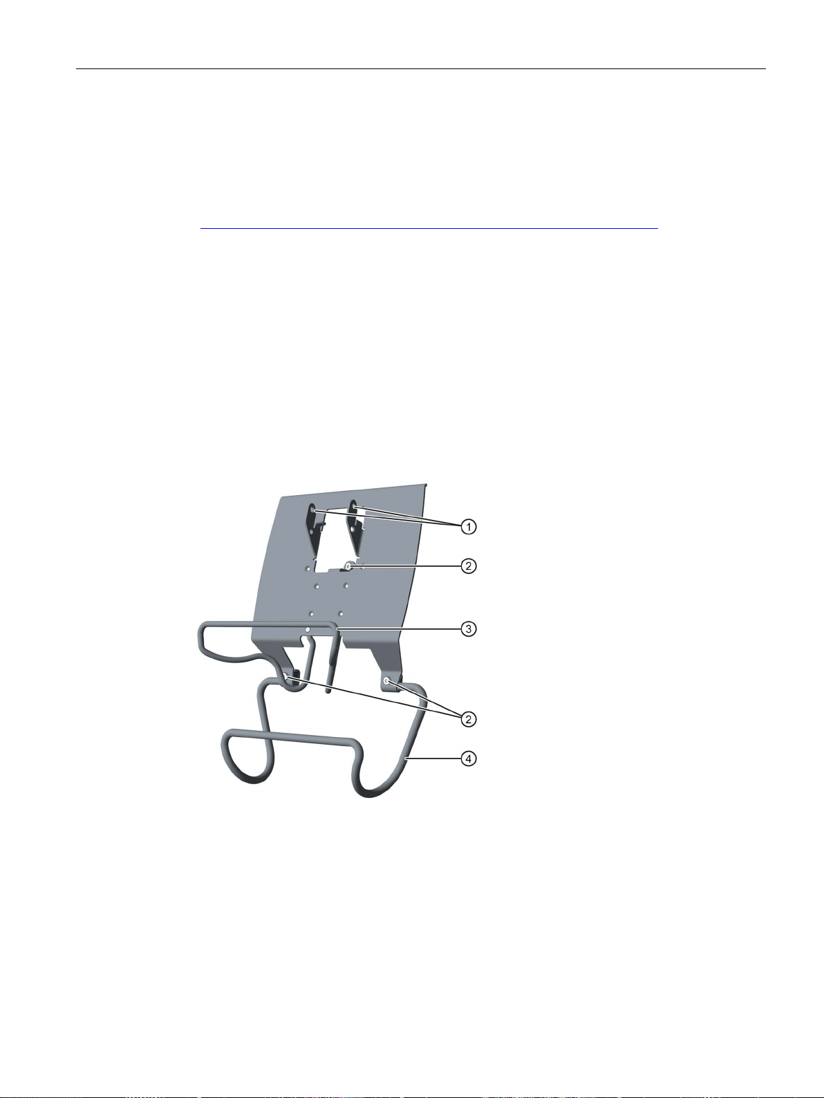
1.6.1
KTP Mobile wall-mounting bracket
①
Hooks for the handle on the Mobile Panel
②
Screw flange
③
Safety bar for the Mobile Panel
④
Holding bracket for the connecting cable
1.6 Accessories
Accessories are not included in the scope of delivery but can be ordered from the following
address:
HMI accessories
(https://mall.industry.siemens.com/mall/en/WW/Catalog/Products/10144445
In the Industry Mall you can find the following accessories for the HMI devices of type KTP
Mobile, for example:
● KTP Mobile wall-mounting bracket
● KTP Mobile spare key
● Memory card
● Protective film
The wall-mounting bracket holds the Mobile Panel securely in place during stationary
operation.
)
The assembly of the KTP Mobile wall-mounting bracket is described in the section
"Assembling the KTP Mobile wall-mounting bracket (Page 47)".
Mobile Panels 2nd Generation
Operating Instructions, 09/2018, A5E33876626-AC
21

Overview
1.6.2
Fail-safe KTP Mobile spare key
1.6.3
Protective films
1.6.4
Storage media
1.6 Accessories
The KTP Mobile spare key is part of the keyswitch for the fail-safe Mobile Panel 2nd
Generation. See section "Keyswitches, function keys and illuminated pushbuttons
(Page 79)".
The protective film prevents the touch screen from getting scratched and dirty during
operation. One set of protective film contains 10 protective films.
● Protective film 4" touch devices, type 13
● Protective film 7" touch devices, type 13
● Protective film 9" touch devices, type 13
You can use the storage media to back up Mobile Panel data and copy data to the Mobile
Panel. Use the following storage media:
● SIMATIC HMI Memory Card
Siemens AG has approved the use of SD memory cards in the Mobile Panel.
● USB flash drive
The USB flash drive must be suitable for industrial applications. The storage medium is
inserted in the port on the left of the device.
Mobile Panels 2nd Generation
22 Operating Instructions, 09/2018, A5E33876626-AC

Overview
1.6.5
SIRIUS safety relays
Note
Evaluation of the safety-related operator controls via F-DI modules
Instead of a SIRIUS safety relay, F
The F
SIL/performance level and category. Depending on the safety integrity level SIL/performance
level and category required, the following functions are, for example, to be used for the F
modules:
•
•
•
•
The plant operator/system engineer is resp
hardwired F
DI modules.
See also
1.6 Accessories
If you are using a fail-safe Mobile Panel in a hardwired F system, you must use a safety
relay.
The Mobile Panels 2nd Generation have been tested with the following safety relays and
approved:
● SIRIUS safety relay, standard, relay output
article number 3SK1111-1AB30
● SIRIUS safety relay, standard, electronic output
article number 3SK1112-1BB40
● SIRIUS safety relay, advanced, relay output
article number 3SK1121-1AB40
● SIRIUS safety relay, advanced, electronic output
article number 3SK1122-1AB40
You can find the complete portfolio of the SIRIUS 3SK safety relays on the Internet
(http://www.siemens.com/product?3SK
).
-DI modules used must be appropriate for the required safety integrity level
Short- and cross-circuit monitoring
Discrepancy monitoring
Short-circuit detection
Cross-circuit detection
-system with evaluation of the safety-related operator controls via one or more F-
FAQs Mobile Panels 2nd Generation
(https://support.industry.siemens.com/cs/ww/en/ps/14746/faq
-DI modules can be used for the evaluation.
-DI
onsible for checking the proper functioning of the
)
Mobile Panels 2nd Generation
Operating Instructions, 09/2018, A5E33876626-AC
23

Overview
1.7
Software required
Configuration software
KTP700 Mobile, KTP700F Mobile, KTP900 Mobile, KTP900F Mobile
KTP400F Mobile
See also
1.8
Terms for fail-safe operation
1.7 Software required
You need one of the following software products to configure the HMI devices:
● WinCC Comfort V13 SP1 Update 4 or higher
● WinCC Advanced V13 SP1 Update 4 or higher
To operate a fail-safe Mobile Panel in a PROFIsafe-based F-system, you need the optional
package STEP 7 Safety Advanced V13 SP1 or higher.
You need one of the following software products to configure the KTP400F Mobile:
● WinCC Comfort V13 SP1 Update 6 or higher
● WinCC Advanced V13 SP1 Update 6 or higher
You also need the HSP0168 HMI KTP400F Mobile V1.0 or higher.
To operate a KTP400F Mobile in a PROFIsafe-based F-system, you need the optional
package STEP 7 Safety Advanced V13 SP1 or higher.
Configuring a fail-safe Mobile Panel (Page 170)
This section defines terms relating to fail-safe operation with a fail-safe HMI device.
You can find additional information on the topic of "Safety" in the following document:
"SIMATIC Safety - Configuring and Programming" programming and operating manual
(http://support.automation.siemens.com/WW/view/en/54110126
)
Mobile Panels 2nd Generation
24 Operating Instructions, 09/2018, A5E33876626-AC

Overview
Fail-safe automation system, F system
Safe operating state
1.8 Terms for fail-safe operation
A fail-safe automation system is required in a plant with high safety requirements.
An F-system is characterized by the following features:
● Safety-related shutdown response of the system after the triggering of a stop or
emergency stop via a safety-related operator control.
● The confirmation of machine movements entailing danger via an enabling mechanism.
The following F-systems iIn conjunction with a fail-safe Mobile Panel are distinguished in this
document:
● Hardwired F-system: The safety-related operator controls are wired to a safety relay. If
one of the safety-related operator controls is activated, the safety relay triggers the safe
state or confirms a machine movement entailing danger in the F-system via the enabing
button.
● PROFIsafe-based F-system: The signals of the safety-related operator controls are
transmitted to the F-system via PROFIsafe.
Safety-related devices with fail-safe controllers communicate with PROFIsafe via
PROFINET to enable these devices to be used in fail-safe automation systems up to
SIL3. PROFIsafe implements safety-related communication with a special user data
format and a special protocol. PROFIsafe is specified for PROFINET in the standard IEC
61784-3.
If an unexpected event occurs during plant operation that poses a risk to persons or
equipment, the plant must respond with a defined safety shutdown. Protection of personnel
against physical injury can only be ensured if intervention in manufacturing processes, for
example during retrofitting or troubleshooting, is safe and secure.
Based on the risk analysis, the safety shutdown and therefore the shutdown response of the
plant must therefore be configured to ensure that the plant or plant area can be switched to a
safe operating state in the event of a risk.
In addition to the qualitative risk analysis required, the machine operator also has an
obligation to make a quantitative assessment of potential hazards. On this basis, the
operator must then establish what risks could arise during plant or plant area operation and
whether the relevant safety functions are sufficiently effective for the hazard in question.
The safe operating state is assigned to the fail-safe controller by a safety program. The plant
constructor is responsible for the required configuration which should be described in the
plant documentation.
Mobile Panels 2nd Generation
Operating Instructions, 09/2018, A5E33876626-AC
25

Overview
Safety-related operator controls
Fail-safe operation
Emergency stop, stop
1.8 Terms for fail-safe operation
A fail-safe Mobile Panel comes equipped with the two safety-related operator controls
"Emergency stop / stop button" and "Acknowledgment button". All other operator controls are
not safety-related operator controls.
In a hardwired or PROFIsafe-based F-system, you operate the plant or a plant section in failsafe mode. In fail-safe mode, the safety-related operator controls emergency stop/stop
button and enabling buttons are active.
● For a hardwired F-system: Fail-safe mode runs via a fixed connection with a safety relay.
● In a PROFIsafe-based F-system: The HMI device in fail-safe mode detects the signals of
the "emergency stop / stop button" and "enabling button" safety-related operator controls;
communication with the F-system is performed via PROFIsafe.
When configuring the safety functions with the STEP 7 Safety Advanced optional
package, fail-safe operation according to SIL 3 or Performance Level e and Category 4 is
possible with an HMI device of the type KTPx00F Mobile.
The safety-related operator controls can be configured as fail-safe inputs in the safety
program.
The operator presses the emergency stop / stop button to activate either an emergency stop
or a stop.
● The emergency stop is an emergency action that is intended to stop a process or
movement entailing danger. All machines that are assigned to the trigger are immediately
brought to a safe state via the emergency stop.
● The emergency stop / stop button of the HMI device brings about a safety-related stop of
the plant or machine in accordance with EN 60204-1, Section 9.2.5.3.
Whether the emergency stop / stop button causes an "emergency stop" or "stop" function
must be decided upon and configured on the basis of the risk assessment.
Mobile Panels 2nd Generation
26 Operating Instructions, 09/2018, A5E33876626-AC

Overview
Safety-related operating mode
stop button
emergency stop
button
emergency stop
button
Emergency stop / stop bypass
PROFIsafe communication, logon and logoff in the safety program
Mobile Panel logon
1.8 Terms for fail-safe operation
In fail-safe mode, you can use the HMI device in combination with a connection box in one of
the following operating modes:
● Stop button evaluated by safety relay
This operating mode is intended for a hardwired F-system. The signals of the safetyrelated operator controls are wired to a safety relay. If you press the
emergency stop / stop button, the plant typically responds with a stop.
The emergency stop / stop button does not light up.
In this operating mode, the emergency stop / stop button is called the
● E-stop button evaluated by safety relay
This operating mode is intended for a hardwired F-system. The signals of the safetyrelated operator controls are wired to a safety relay. When you press the emergency stop
/ stop button, the plant responds with an emergency stop.
The emergency stop / stop button lights up when active.
In this operating mode, the emergency stop / stop button is called the
.
● E-stop button evaluated by PROFIsafe
This operating mode is intended for a PROFIsafe-based F-system. If you press the
emergency stop / stop button, an emergency stop is triggered in the plant.
The emergency stop / stop button lights up when active, that is, if the HMI device has
been registered in the safety program.
In this operating mode, the emergency stop / stop button is called the
.
.
The emergency stop / stop bypass is a function of the connection box advanced for
hardwired F-systems.
The function ensures that no stop or emergency stop will be triggered in the plant when
reconnecting the Mobile Panel to another connection box.
The following applies in a PROFIsafe-based F-system for the logon and logoff of the fail-safe
Mobile Panel to a safety program:
If you have connected the fail-safe HMI device with a connection box and started the HMI
project, the HMI device is automatically logged onto the safety program. After logon, the failsafe HMI device is integrated into PROFIsafe communication and the emergency stop button
and enabling button become active.
Mobile Panels 2nd Generation
Operating Instructions, 09/2018, A5E33876626-AC
27

Overview
Mobile Panel logoff
Connection point recognition
1.9
Organizational measures
Measures
1.9 Organizational measures
Before disconnecting the fail-safe HMI device from a connection box, you must log off the
HMI device using an appropriate operator control of the safety program or close the current
project. Logoff must be confirmed in a dialog. When you log off, the HMI device is removed
from PROFIsafe communication. After logging off, the emergency stop button and enabling
button are no longer active. You can therefore disconnect the HMI device from the
connection box.
For the HMI devices KTP700F Mobile and KTP900F Mobile: If you logged off the HMI device
without closing the project from the safety program, the project remains active on the HMI
device for the duration of the backup time and you can plug the HMI device into another
connection box. After plugging into another connection box and automatic logon to the safety
program, you can continue working with the current project in fail-safe mode.
If you disconnect the fail-safe Mobile Panel without logging off the connection box, a
PROFIsafe communication error occurs and the plant goes into safe operating mode
according to the configured shutdown behavior.
The connection point recognition is a function that you can configure for connection boxes.
Once you have configured connection point recognition, you can determine the plant area in
which an HMI device is connected and the connection box used for this. This provides the
following functions, for example:
● Display of screens on the HMI device for specific plant areas
● Emergency stop / stop for specific plant areas
If you are using a fail-safe Mobile Panel in a fail-safe system, you must consider the
following organizational measures:
● Install stationary emergency stop or emergency off buttons in the plant that are effective
independent of the Mobile Panel.
● Perform a risk assessment of the plant.
● If the overall plant is not to be monitored from a single location, configure plant areas.
● Select the same operating mode for all connection boxes in a contiguous plant area.
● Create a safety program.
● Run an acceptance test on the fail-safe automation system.
Mobile Panels 2nd Generation
28 Operating Instructions, 09/2018, A5E33876626-AC

Overview
F-systems
Connection box
PROFIsafe-
based F-system
Hardwired F-system, no
emergency stop/stop bypass
Hardwired F-system with
emergency stop/stop bypass
compact
Yes
Yes
No
advanced
Yes
No
Yes
safety relay
safety relay
1.10
Mobile Panel and connection box compatibility
Ccompatibility of Mobile Panels 2nd Generation – connection box PN Basic and PN Plus
1.10 Mobile Panel and connection box compatibility
The table below shows the F-systems that can be configured or installed for a given
connection box. Requirement is that you are using a fail-safe Mobile Panel.
standard Yes Yes No
Safety-related
operating mode
E-stop button
evaluated by
PROFIsafe
Stop button evaluated by
safety relay
E-stop button evaluated by
Stop button evaluated by
safety relay
E-stop button evaluated by
This section addresses the following compatibility:
● Ccompatibility of Mobile Panels 2nd Generation to connection box PN Basic and PN Plus
● Ccompatibility of Mobile Panels 1st Generation to connection boxes compact, standard
und advanced
The Mobile Panels 2nd Generation are not compatible with the connection box DP Basic and
connection box DP Plus.
The 2nd Generation Mobile Panels are compatible with the following connection boxes:
● Connection box PN Basic, article number 6AV6671-5AE01-0AX0
● Connection box PN Plus, article number 6AV6671-5AE11-0AX0
Mobile Panels 2nd Generation
Operating Instructions, 09/2018, A5E33876626-AC
Restrictions:
● Only one hardwired F-system with a stop function and enabling function is permitted.
● PROFINET communication is possible with the connection boxes PN Basic and PN Plus,
a PROFIsafe -based F-system is not feasible.
● Note the reduced maximum permissible amperage for the acknowledgment button circuit
in the technical specifications, section "Connection boxes (Page 236)".
29

Overview
Compatibility of Mobile Panels 1st Generation – connection boxes of the Mobile Panel 2nd
Generation
1.10 Mobile Panel and connection box compatibility
You can use the connection box compact, the connection box standard and the connection
box advanced with the following predecessor devices:
● Mobile Panel 177 PN
Article numbers 6AV6645-0BA01-0AX0, 6AV6645-0BB01-0AX0, 6AV6645-0BC01-0AX0
● Mobile Panel 277 8"
Article numbers 6AV6645-0CA01-0AX0, 6AV6645-0CB01-0AX0, 6AV6645-0CC01-0AX0
● Mobile Panel 277 10"
Article number 6AV6645-0BE02-0AX0
Restrictions:
● Only one hardwired system F-system with a stop function and enabling function is
permitted with a Mobile Panel 1st Generation.
● PROFIsafe communication is not possible with predecessor devices, therefore a
PROFIsafe -based F-system is not feasible.
● The "Mobile Panel inserted" signal is not available on the connection boxes of the Mobile
Panel 2nd Generation.
● The "Control" signal is not available on the connection boxes of the Mobile Panel 2nd
Generation.
Mobile Panels 2nd Generation
30 Operating Instructions, 09/2018, A5E33876626-AC
 Loading...