

Siemens SIMATIC HMI KTP700 Basic, SIMATIC HMI KTP900 Basic, SIMATIC HMI KTP1200 Basic DP, SIMATIC HMI KTP700 Basic DP, SIMATIC HMI KTP1200 Basic Basic Operating Instructions Manual

___________________
___________________
___________________
___________________
___________________
___________________
___________________
___________________
___________________
___________________
___________________
SIMATIC HMI
HMI devices
Basic Panels 2nd Generation
Operating Instructions
10/2016
A5E33293231
Preface
Overview
1
Safety instructions
2
Mounting and connecting
3
Operating the device
4
Configuring the device
5
Commissioning a project
6
Maintenance and care
7
Technical specifications
8
Technical Support
A
Abbreviations
B
-AB

Siemens AG
Division Digital Factory
Postfach 48 48
90026 NÜRNBERG
GERMANY
A5E33293231-AB
Ⓟ
Copyright © Siemens AG 2016.
All rights reserved
Legal information
Warning notice system
DANGER
indicates that death or severe personal injury will result if proper precautions are not taken.
WARNING
indicates that death or severe personal injury may result if proper precautions are not taken.
CAUTION
indicates that minor personal injury can result if proper precautions are not taken.
NOTICE
indicates that property damage can result if proper precautions are not taken.
Qualified Personnel
personnel qualified
Proper use of Siemens products
WARNING
Siemens products may only be used for the applications described in the catalog and in the relevant technical
ambient conditions must be complied with. The information in the relevant documentation must be observed.
Trademarks
Disclaimer of Liability
This manual contains notices you have to observe in order to ensure your personal safety, as well as to prevent
damage to property. The notices referring to your personal safety are highlighted in the manual by a safety alert
symbol, notices referring only to property damage have no safety alert symbol. These notices shown below are
graded according to the degree of danger.
If more than one degree of danger is present, the warning notice representing the highest degree of danger will
be used. A notice warning of injury to persons with a safety alert symbol may also include a warning relating to
property damage.
The product/system described in this documentation may be operated only by
task in accordance with the relevant documentation, in particular its warning notices and safety instructions.
Qualified personnel are those who, based on their training and experience, are capable of identifying risks and
avoiding potential hazards when working with these products/systems.
Note the following:
documentation. If products and components from other manufacturers are used, these must be recommended
or approved by Siemens. Proper transport, storage, installation, assembly, commissioning, operation and
maintenance are required to ensure that the products operate safely and without any problems. The permissible
All names identified by ® are registered trademarks of Siemens AG. The remaining trademarks in this publication
may be trademarks whose use by third parties for their own purposes could violate the rights of the owner.
We have reviewed the contents of this publication to ensure consistency with the hardware and software
described. Since variance cannot be precluded entirely, we cannot guarantee full consistency. However, the
information in this publication is reviewed regularly and any necessary corrections are included in subsequent
editions.
for the specific
11/2016 Subject to change

Preface
Purpose of the operating instructions
Target group
Chapter
All
Operators
the process control phase.
Commissioning engineers
section "Maintenance and servicing."
Service technicians
"Maintenance and servicing."
Maintenance technicians
maintenance work during the process control phase.
These operating instructions provide information based on the requirements defined by
IEC 62079 for documentation. This information relates to the HMI device, its storage,
transportation, place of use, installation, use and maintenance.
These operating instructions are intended for a variety of target groups. The following table
shows the chapters of these operating instructions that are of particular importance for the
respective target group.
"Safety instructions"
The operator operates and monitors the system during
"Overview"
"Operating the device"
The commissioning engineer integrates the HMI device
into the system and ensures the operating capability of
the HMI device for the process control phase.
Service technicians rectify faults that occur during the
process control phase.
Maintenance technicians carry out servicing and
The information system of WinCC contains additional information. The information system is
integrated as online help in WinCC and contains instructions, examples and reference
information in electronic form.
All chapters.
Depending on the use of the HMI device,
certain chapters may not be of relevance to
the commissioning engineer, e.g. the
All chapters.
Depending on the use of the HMI device,
certain chapters may not be of relevance to
the service technicians, e.g. the section
Maintenance and care
Basic Panels 2nd Generation
Operating Instructions, 10/2016, A5E33293231-AB
3
Preface
Scope
Device designation
SIMATIC HMI
Device type
Interface type
Can be configured with
KTP400 Basic
PROFINET
KTP700 Basic DP
PROFIBUS
KTP900 Basic
PROFINET
KTP1200 Basic
PROFINET
KTP1200 Basic DP
PROFIBUS
1
higher.
Basic knowledge required
These operating instructions are valid for all versions of the SIMATIC HMI Basic Panels. The
following naming conventions apply:
KTP700 Basic PROFINET
Devices are configurable as of WinCC V13. The description in this manual relates to V14 or
Knowledge of automation technology and process communication is necessary to
understand the operating instructions.
An understanding of the use of computers and operating systems is also required.
Touch device with
function keys
WinCC (TIA Portal) as of V13 1
Basic Panels 2nd Generation
4 Operating Instructions, 10/2016, A5E33293231-AB
Preface
Illustrations and text highlighting
Graphical highlighting
Description
in the figures as a representation of
Text highlighting
Scope
commands
<F1>
Keyboard operation
This manual contains figures of the described devices. The figures may deviate from the
supplied device in certain details.
The following graphical highlighting facilitates reading these operating instructions:
If the instructions involve several
tasks, the individual tasks are
highlighted by a red number circle.
A light blue highlight indicates
components and tools that are
required in the course of a task.
KTP700 Basic is sometimes shown
all Basic Panels.
Basic Panels 2nd Generation
Operating Instructions, 10/2016, A5E33293231-AB
The following text highlighting facilitates reading these operating instructions:
"Add screen"
"File > Edit" Operational sequences, for example, menu commands, shortcut menu
• Terms that appear in the user interface, for example, dialog names, tabs,
buttons, menu commands
• Input values, for example, limits, tag values
• Path information
5

Preface
Note
A note contains important information on described products and their handling or on a
section of this documentation.
Names of the software
Names of the hardware
Trademarks
Note information highlighted as follows:
Configuration and runtime software have different names as follows:
● "WinCC (TIA Portal) V13", for example, refers to the configuration software.
The term "WinCC" is used in a general context. The full name is always used when it is
necessary to differentiate between different versions of the configuration software.
● "WinCC Runtime" refers to the runtime software that can run on HMI devices.
These operating instructions describe the new "Basic Panels 2nd Generation" which
replaces the current Basic Panels. The term "Basic Panel" is used synonymously for a
"Basic Panel 2nd Generation" in these instructions.
Names labeled with a ® symbol are registered trademarks of the Siemens AG. Other names
used in this documentation may be trademarks, the use of which by third parties for their
own purposes could violate the rights of the owner.
®
● HMI
● SIMATIC
● SIMATIC HMI
● WinCC
®
®
®
Basic Panels 2nd Generation
6 Operating Instructions, 10/2016, A5E33293231-AB

Table of contents
Preface ................................................................................................................................................... 3
1 Overview............................................................................................................................................... 11
2 Safety instructions ................................................................................................................................. 17
3 Mounting and connecting ...................................................................................................................... 21
4 Operating the device ............................................................................................................................. 39
1.1 Product overview .................................................................................................................... 11
1.2 Design of the PROFINET devices .......................................................................................... 12
1.3 Design of the PROFIBUS devices .......................................................................................... 13
1.4 Scope of delivery .................................................................................................................... 14
1.5 Accessories ............................................................................................................................. 15
2.1 General safety instructions ..................................................................................................... 17
2.2 Notes about usage .................................................................................................................. 19
3.1 Preparations ............................................................................................................................ 21
3.1.1 Checking the package contents .............................................................................................. 21
3.1.2 Checking the operating conditions .......................................................................................... 21
3.1.3 Selecting a mounting position ................................................................................................. 22
3.1.4 Checking clearances............................................................................................................... 23
3.1.5 Making the mounting cutout .................................................................................................... 24
3.2 Mounting the HMI device ........................................................................................................ 25
3.3 Connecting the HMI device ..................................................................................................... 27
3.3.1 Connection sequence ............................................................................................................. 27
3.3.2 Connecting the equipotential bonding circuit .......................................................................... 28
3.3.3 Connecting the power supply ................................................................................................. 29
3.3.4 Connecting a programming device ......................................................................................... 31
3.3.5 Connecting the configuration PC ............................................................................................ 31
3.3.6 Connecting the controller ........................................................................................................ 33
3.3.7 Connecting a USB device ....................................................................................................... 35
3.4 Switching on and testing the HMI device ................................................................................ 36
3.5 Securing the cables ................................................................................................................ 38
4.1 Overview ................................................................................................................................. 39
4.2 General functions of the screen keyboard .............................................................................. 41
4.3 The screen keyboards ............................................................................................................ 42
4.4 Entering data ........................................................................................................................... 46
Basic Panels 2nd Generation
Operating Instructions, 10/2016, A5E33293231-AB
7

Table of contents
5 Configuring the device .......................................................................................................................... 47
6 Commissioning a project ....................................................................................................................... 73
5.1 Opening the settings .............................................................................................................. 47
5.2 Overview of functions ............................................................................................................. 49
5.3 Save to external storage medium – Backup .......................................................................... 50
5.4 Restore from external storage medium – Restore ................................................................. 51
5.5 Load project from external storage medium .......................................................................... 52
5.6 Update operating system from external storage medium ...................................................... 53
5.7 Changing the IP address and device name of a controller .................................................... 54
5.8 Editing communication connections....................................................................................... 55
5.9 Configuring the time server .................................................................................................... 56
5.10 Enter time and date ................................................................................................................ 57
5.11 Activating the acoustic signal ................................................................................................. 58
5.12 Configuring Autostart or wait time .......................................................................................... 59
5.13 Changing the password settings ............................................................................................ 60
5.14 Displaying licensing information for the HMI device .............................................................. 61
5.15 Displaying information about the HMI device ........................................................................ 62
5.16 Change network settings of PROFINET devices ................................................................... 63
5.17 Change network settings of PROFIBUS devices ................................................................... 64
5.18 Assigning transfer parameters ............................................................................................... 65
5.19 Configure Sm@rt Server ........................................................................................................ 66
5.20 Importing a certificate via USB ............................................................................................... 67
5.21 Displaying and deleting certificates ....................................................................................... 68
5.22 Calibrating the touch screen .................................................................................................. 69
5.23 Changing the monitor settings ............................................................................................... 70
5.24 Setting the screen saver ........................................................................................................ 71
6.1 Overview ................................................................................................................................ 73
6.2 Operating modes.................................................................................................................... 74
6.3 Data transmission options ...................................................................................................... 75
6.4 Transfer .................................................................................................................................. 75
6.4.1 Overview ................................................................................................................................ 75
6.4.2 Starting the manual transfer ................................................................................................... 75
6.4.3 Starting the transfer automatically ......................................................................................... 77
6.4.4 Testing a project..................................................................................................................... 78
Basic Panels 2nd Generation
8 Operating Instructions, 10/2016, A5E33293231-AB

Table of contents
7 Maintenance and care ........................................................................................................................... 95
8 Technical specifications ........................................................................................................................ 97
6.5 Backup and restore ................................................................................................................. 80
6.5.1 Overview ................................................................................................................................. 80
6.5.2 Backup and restore using ProSave ........................................................................................ 81
6.5.3 Backup and restore using WinCC ........................................................................................... 82
6.6 Updating the operating system - Basic Panel DP ................................................................... 83
6.6.1 Overview ................................................................................................................................. 83
6.6.2 Resetting the factory settings ................................................................................................. 84
6.6.3 Updating the operating system using ProSave ...................................................................... 84
6.7 Updating the operating system - Basic Panel with PROFINET interface ............................... 85
6.7.1 Overview ................................................................................................................................. 85
6.7.2 Resetting the factory settings ................................................................................................. 86
6.7.3 Updating the operating system using ProSave ...................................................................... 87
6.7.4 Updating the operating system using WinCC ......................................................................... 88
6.7.5 Resetting to factory settings with ProSave ............................................................................. 89
6.7.6 Resetting to factory settings with WinCC................................................................................ 90
6.8 Reset to factory settings via USB ........................................................................................... 91
6.9 Managing WinCC options ....................................................................................................... 92
6.10 Transferring a license key ....................................................................................................... 93
7.1 Maintenance and care ............................................................................................................ 95
7.2 Recycling ................................................................................................................................ 96
8.1 Certificates and approvals ...................................................................................................... 97
8.2 Electromagnetic compatibility ................................................................................................. 99
8.2.1 Emitted interference ................................................................................................................ 99
8.2.2 Immunity to interferences ....................................................................................................... 99
8.3 Mechanical ambient conditions ............................................................................................... 99
8.3.1 Transport and storage conditions ........................................................................................... 99
8.3.2 Operating Conditions .............................................................................................................. 99
8.4 Climatic ambient conditions .................................................................................................. 100
8.4.1 Long-term storage ................................................................................................................. 100
8.4.2 Transport and short-term storage ......................................................................................... 100
8.4.3 Operating Conditions ............................................................................................................ 101
8.4.4 Climate diagram .................................................................................................................... 101
8.5 Information on insulation tests, protection class and degree of protection........................... 102
8.6 Dimension drawings .............................................................................................................. 103
8.6.1 Dimensional drawing of KTP400 Basic................................................................................. 103
8.6.2 Dimensional drawing of KTP700 Basic................................................................................. 104
8.6.3 Dimensional drawing of KTP700 Basic DP .......................................................................... 105
8.6.4 Dimensional drawing of KTP900 Basic................................................................................. 106
8.6.5 Dimension drawings of KTP1200 Basic................................................................................ 107
8.6.6 Dimensional drawing of KTP1200 Basic DP ........................................................................ 108
Basic Panels 2nd Generation
Operating Instructions, 10/2016, A5E33293231-AB
9

Table of contents
A Technical Support ................................................................................................................................ 119
B Abbreviations ....................................................................................................................................... 121
Glossary .............................................................................................................................................. 123
Index ................................................................................................................................................... 129
8.7 Technical specifications ....................................................................................................... 109
8.7.1 Power supply ........................................................................................................................ 109
8.7.2 KTP400 Basic, KTP700 Basic and KTP700 Basic DP ........................................................ 109
8.7.3 KTP900 Basic, KTP1200 Basic and KTP1200 Basic DP .................................................... 111
8.8 Interface description ............................................................................................................. 113
8.8.1 Power supply ........................................................................................................................ 113
8.8.2 PROFIBUS (Sub-D RS422/485) .......................................................................................... 113
8.8.3 PROFINET (LAN)................................................................................................................. 114
8.8.4 USB ...................................................................................................................................... 114
8.9 Scope of functions with WinCC ............................................................................................ 115
A.1 Service and support ............................................................................................................. 119
A.2 System events...................................................................................................................... 120
Basic Panels 2nd Generation
10 Operating Instructions, 10/2016, A5E33293231-AB

1
1.1
Product overview
The beauty of simplicity
New, cost-efficient HMI generation meets the trend for high-quality visualization even in
small machines and plants
Siemens meets the requirements of users for high-quality visualization and operation even in
small and medium-size machines and plants with the second generation of SIMATIC HMI
Basic Panels. While the price of the new devices is based on the current panels, their scope
of performance has been expanded tremendously. The high resolution and a color depth of
up to 65,500 colors are major factors contributing to the increased performance.
Even the connectivity either by PROFINET or PROFIBUS interface plus USB port could be
significantly improved. Configuration and operation of the new panels has become easier in
connection with simplified programming by means of the new WinCC software version in the
TIA Portal.
Basic Panels 2nd Generation
Operating Instructions, 10/2016, A5E33293231-AB
11
Overview
1.2
Design of the PROFINET devices
①
Power supply connection
⑥
Mounting seal
②
USB port
⑦
Function keys
③
PROFINET interface
⑧
Rating plate
④
Recesses for a mounting clip
⑨
Connection for functional ground
⑤
Display/touch screen
⑩
Guide for labeling strips
1.2 Design of the PROFINET devices
The figure below shows the design of the PROFINET devices using KTP700 Basic as an
example.
Basic Panels 2nd Generation
12 Operating Instructions, 10/2016, A5E33293231-AB
Overview
1.3
Design of the PROFIBUS devices
①
Power supply connection
⑥
Mounting seal
②
RS 422/RS 485 port
⑦
Function keys
③
USB port
⑧
Rating plate
④
Recesses for a mounting clip
⑨
Functional earth connection
⑤
Display/touch screen
⑩
Guides for labeling strips
1.3 Design of the PROFIBUS devices
The figure below shows the design of the PROFIBUS devices using KTP700 Basic DP as an
example.
Basic Panels 2nd Generation
Operating Instructions, 10/2016, A5E33293231-AB
13
Overview
1.4
Scope of delivery
Name
Figure
Quantity
1.4 Scope of delivery
The scope of delivery of the HMI device includes the following components:
HMI device
Quick Installation Guide
Mounting clips with
grub screw
Power supply connector
1
1
According to the quantity required
for mounting, in accessory kit
1, in accessory kit
Basic Panels 2nd Generation
14 Operating Instructions, 10/2016, A5E33293231-AB

Overview
1.5
Accessories
Storage media and I/O devices
Name
Article number
SIMATIC PC USB flash drive
6ES7648-0DC50-0AA0
Converters, adapters and connectors
Name
Purpose
Article number
converter
Basic Panels DP
90 degree elbow adapter
For RS 422/RS 485 port, cable outlet to rear
6AV6671-8XD00-0AX0
straight cable outlet
"IE FC RJ45 Plug 2x2"
Protective films
Name
Purpose
Article number
Protective film 4"
Protective film set for KTP400 Basic
6AV2124-6DJ00-0AX0
KTP700 Basic DP
Protective film 9"
Protective film set for KTP900 Basic
6AV2181-3JJ20-0AX0
KTP1200 Basic DP
Service packages
Name
Article number
Set of 20 mounting clips
6AV6671-8KX00-0AX2
Set of 10 power supply connectors
6AV6671-8XA00-0AX0
1.5 Accessories
Accessories are not included in the HMI device scope of delivery, but can be ordered on the
Internet under Industry Mall (https://mall.industry.siemens.com
).
This section contains the number of accessories available at the time of publication of the
operating instructions.
Industrial USB Hub 4 6AV6671-3AH00-0AX0
RS 422 to RS 232
PROFIBUS connector Recommended PROFIBUS connector with
PROFINET RJ45
connector
Protective film 7" Protective film set for KTP700 Basic and
Protective film 12" Protective film set for KTP1200 Basic and
Connection of third-party controllers to
Required for connection of Basic Panels with
PROFINET interface to PROFINET
6AV6671-8XE00-0AX0
6GK1500-0FC10
6GK1901-1BB10-2AA0
6AV2124-6GJ00-0AX0
6AV2181-3MJ20-0AX0
Basic Panels 2nd Generation
Operating Instructions, 10/2016, A5E33293231-AB
15

Overview
Other accessories
1.5 Accessories
Additional USB accessories can be found on the Internet in the following entry:
FAQ 19188460 (https://support.industry.siemens.com/cs/ww/en/view/19188460
)
Basic Panels 2nd Generation
16 Operating Instructions, 10/2016, A5E33293231-AB
2
2.1
General safety instructions
Working on the control cabinet
WARNING
Open equipment
Dangerous voltage
Installation as intended
WARNING
Installation only in machinery that conforms to the machinery directive
The HMI device is an open equipment. This means the HMI device may only be installed in
cubicles or cabinets that provide front panel access for operating the device.
The cubicle or cabinet in which the HMI device is installed may only be accessed with a key
or tool and only by trained, authorized personnel.
Opening the cabinet will expose high voltage parts. Contact with these parts could be fatal.
Always disconnect the cabinet from the mains before opening it.
You are not permitted to commission the HMI device unless it has been verified that the
machine in which the HMI device is to be installed complies with directive 2006/42/EC.
Basic Panels 2nd Generation
Operating Instructions, 10/2016, A5E33293231-AB
17
Safety instructions
Strong high-frequency radiation
NOTICE
Observe immunity to high-frequency radiation
ESD
Industrial Security
2.1 General safety instructions
The device has an increased immunity to high frequency radiation according to the
specifications on electromagnetic compatibility in the technical specifications.
Radiation exposure in excess of the specified immunity limits can impair device functions
and result in malfunctions and therefore injuries or damage.
Read the information on immunity to high frequency radiation in the technical specifications.
An electrostatically sensitive device is equipped with electronic components. Due to their
design, electronic components are sensitive to overvoltage and thus to the discharge of
static electricity. Note the corresponding regulations when handling ESD.
Siemens provides products and solutions with industrial security functions that support the
secure operation of plants, systems, machines and networks.
In order to protect plants, systems, machines and networks against cyber threats, it is
necessary to implement – and continuously maintain – a holistic, state-of-the-art industrial
security concept. Siemens’ products and solutions only form one element of such a concept.
Customer is responsible to prevent unauthorized access to its plants, systems, machines
and networks. Systems, machines and components should only be connected to the
enterprise network or the internet if and to the extent necessary and with appropriate security
measures (e.g. use of firewalls and network segmentation) in place.
Additionally, Siemens’ guidance on appropriate security measures should be taken into
account. For more information about industrial security, please visit
(http://www.siemens.com/industrialsecurity
).
Siemens’ products and solutions undergo continuous development to make them more
secure. Siemens strongly recommends to apply product updates as soon as available and to
always use the latest product versions. Use of product versions that are no longer supported,
and failure to apply latest updates may increase customer’s exposure to cyber threats.
To stay informed about product updates, subscribe to the Siemens Industrial Security RSS
Feed under (http://www.siemens.com/industrialsecurity
).
Basic Panels 2nd Generation
18 Operating Instructions, 10/2016, A5E33293231-AB

Safety instructions
Disclaimer for third-party software updates
Notes on protecting administrator accounts
2.2
Notes about usage
NOTICE
The HMI device is approved for indoor use only.
Industrial applications
Use in residential areas
Note
The HMI device is not intended for use in residential areas. Operation of an HMI device in
residential areas can have a negative influence on radio/TV reception.
2.2 Notes about usage
This product includes third-party software. Siemens AG only provides a warranty for
updates/patches of the third-party software, if these have been distributed as part of a
Siemens software update service contract or officially released by Siemens AG. Otherwise,
updates/patches are undertaken at your own risk. You can find more information about our
Software Update Service offer on the Internet at Software Update Service
http://www.automation.siemens.com/mcms/automation-software/en/software-update-
(
service).
A user with administrator privileges has extensive access and manipulation options in the
system.
Therefore, ensure there are adequate safeguards for protecting the administrator accounts
to prevent unauthorized changes. To do this, use secure passwords and a standard user
account for normal operation. Other measures, such as the use of security policies, should
be applied as needed.
The HMI device may be damaged if it is operated outdoors.
Operate the HMI device indoors only.
The HMI device is designed for industrial applications. It conforms to the following standards:
● Requirements of the emission standard for industrial environments,
EN 61000-6-4: 2007 + A1:2011
● ESD immunity requirements to DIN EN 61000-6-2:2005
If the HMI device is used in a residential area, you must ensure compliance with the limits in
technical standard EN 61000-6-3 regarding the emission of radio frequency interference.
Individual acceptance is required.
Basic Panels 2nd Generation
Operating Instructions, 10/2016, A5E33293231-AB
19

Safety instructions
Use with additional measures
Notes on communication
Note
Communication errors caused by address conflict
Communication errors can occur if several devices in a network share the same bus address
or IP address.
Make sure that your HMI device is assigned a unique address in the network.
Note
Updating tag values following a communication error
If communication between an HMI device and controller is interrupted, all tag values
displayed on the HMI device will be replaced by a hash mark ("#").
When the communication between the HMI device and controller is restored, all tag values
will be u
Ethernet communication with Basic Panels with PROFINET interface
Basic Panels with PROFINET interface support the following types of communication:
•
•
2.2 Notes about usage
The HMI device should not be used at the following locations unless additional measures are
taken:
● In locations with a high degree of ionizing radiation
● In locations with severe operating conditions, for example, due to:
– Corrosive vapors, gases, oils or chemicals
– Strong electrical or magnetic fields of high intensity
● In systems that require special monitoring, for example, in:
– Elevators
– Systems in especially hazardous rooms
pdated immediately. The cycle time for updating the tag values begins again at "0".
PROFINET basic function for commissioning and diagnostics
Standard Ethernet communication
Basic Panels 2nd Generation
20 Operating Instructions, 10/2016, A5E33293231-AB

3
3.1
Preparations
3.1.1
Checking the package contents
Note
Damaged parts
Do not install parts damaged during shipment. In the case of damaged parts, contact your
Siemens representative.
3.1.2
Checking the operating conditions
Check the package content for visible signs of transport damage and for completeness.
The package content is described in section Scope of delivery (Page 14).
Keep the provided documentation in a safe place. The documentation is part of the HMI
device and is required for subsequent commissioning.
Note the information in the following sections of these operating instructions before installing
the HMI device:
● Certificates and approvals (Page 97)
● Electromagnetic compatibility (Page 99)
● Mechanical ambient conditions (Page 99)
● Climatic ambient conditions (Page 100)
● Information on insulation tests, protection class and degree of protection (Page 102)
● Technical specifications (Page 109)
Basic Panels 2nd Generation
Operating Instructions, 10/2016, A5E33293231-AB
21
Mounting and connecting
3.1.3
Selecting a mounting position
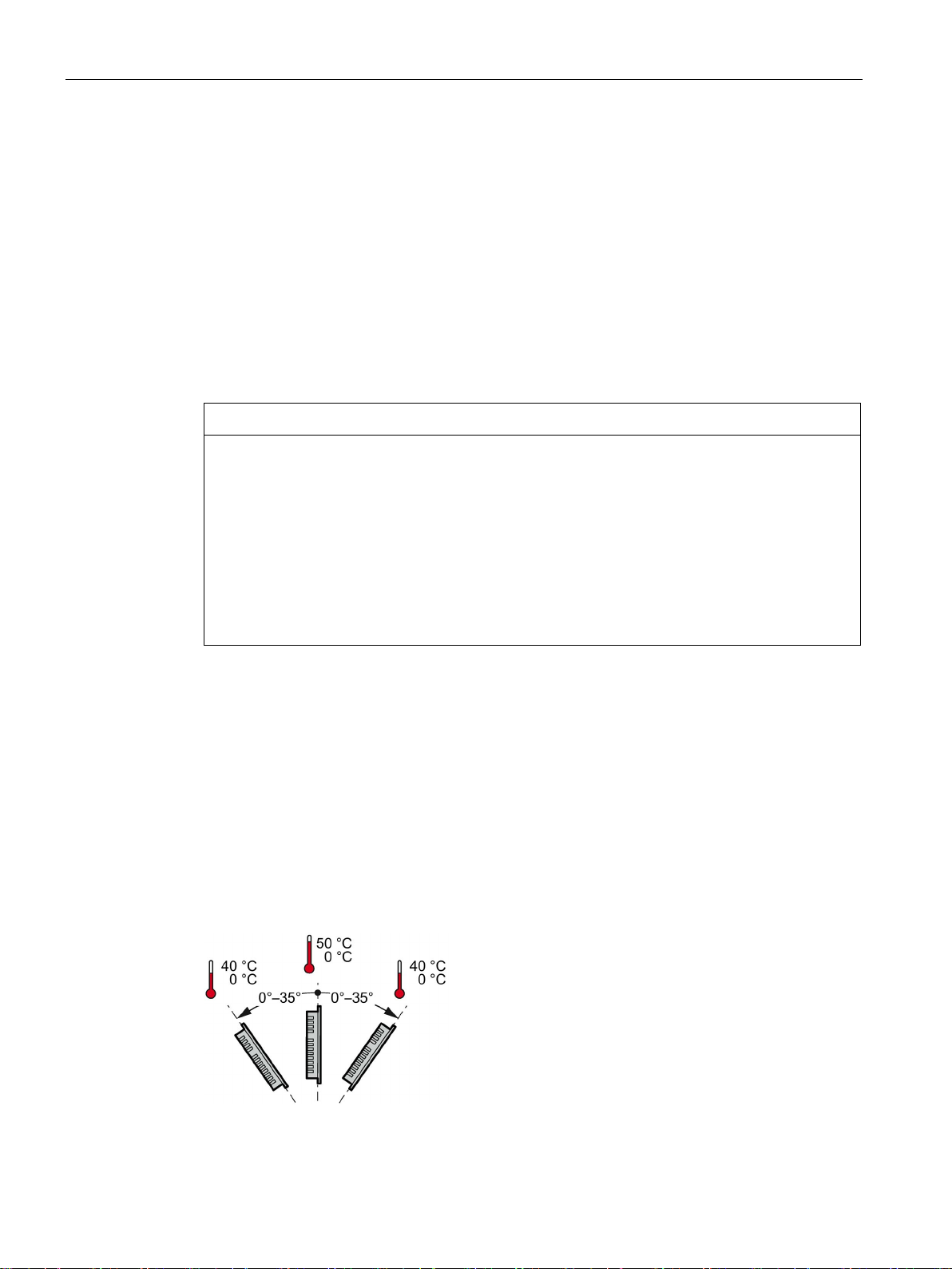
NOTICE
Damage due to overheating
Mounting position
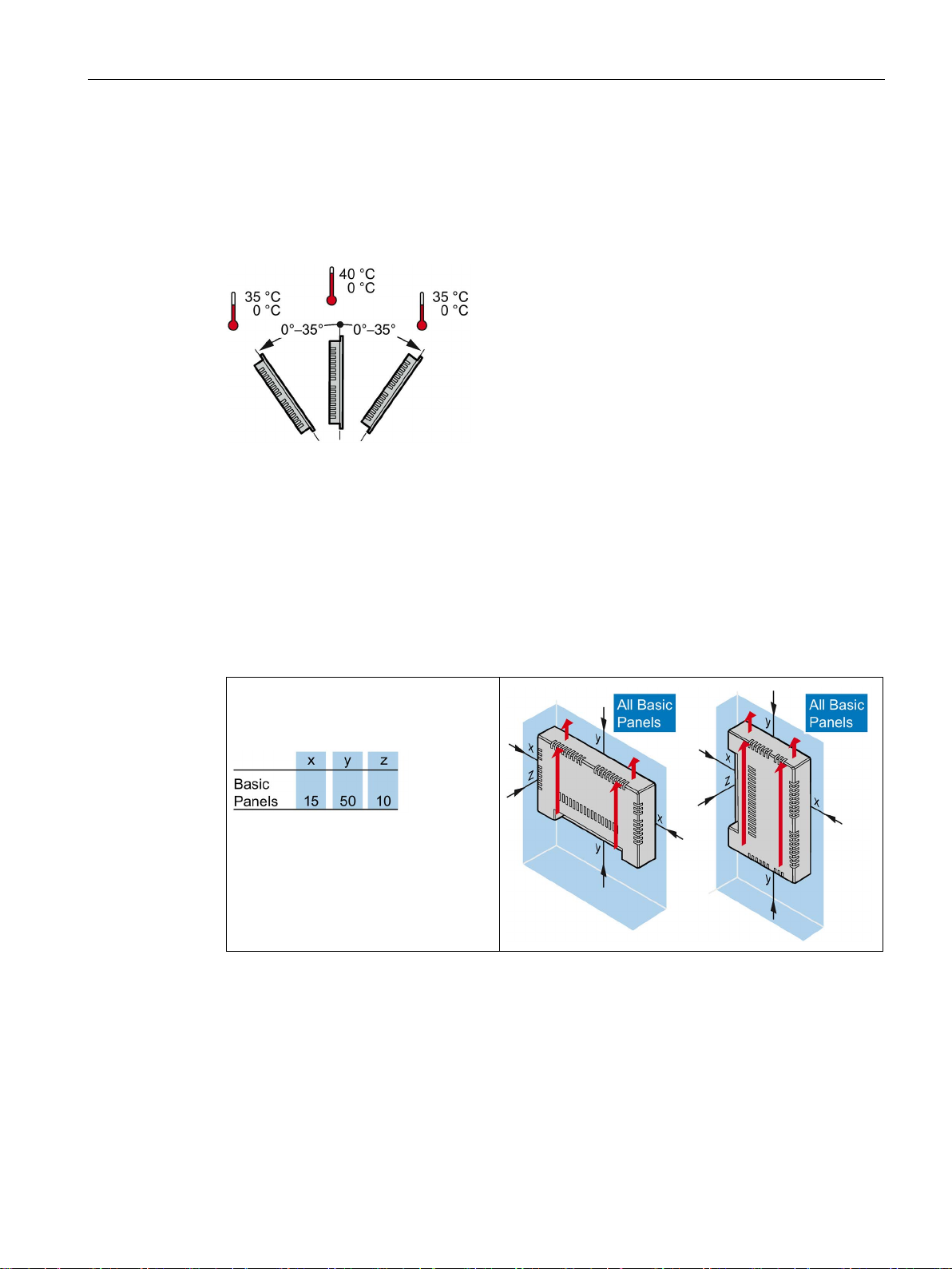
Mounting in horizontal format
3.1 Preparations
The device is suitable for installation in:
● Mounting cabinets
● Control cabinets
● Switchboards
● Consoles
In the following, all of these mounting options are referred to by the general term "cabinet".
The device is self-ventilated and approved for inclined mounting at angles up to +/-35° from
the vertical in stationary cabinets.
Inclined installation reduces the convection by the device and therefore the maximum
permitted ambient temperature for operation.
If there is sufficient forced ventilation, the device can also be operated in the inclined
mounting position up to the maximum permitted ambient temperature for vertical
installation. The device may otherwise be damaged and its certifications and warranty will
be rendered null and void.
The ambient temperature ranges listed in this section apply to the temperature inside the
cabinet.
Select one of the approved mounting positions for your device. The approved mounting
positions are described in the following sections.
Ambient temperature in the cabinet with horizontal mounting:
● Vertical mounting (0° inclined): Maximum +50 °C
● Inclined mounting (inclined up to 35°): Maximum +40 °C
Basic Panels 2nd Generation
22 Operating Instructions, 10/2016, A5E33293231-AB
Mounting and connecting
Mounting in vertical format
See also
3.1.4
Checking clearances
3.1 Preparations
Ambient temperature in the cabinet with vertical mounting:
● Vertical mounting (0° inclined): Maximum +40 °C
● Inclined mounting (inclined up to 35°): Maximum +35 °C
Operating Conditions (Page 101)
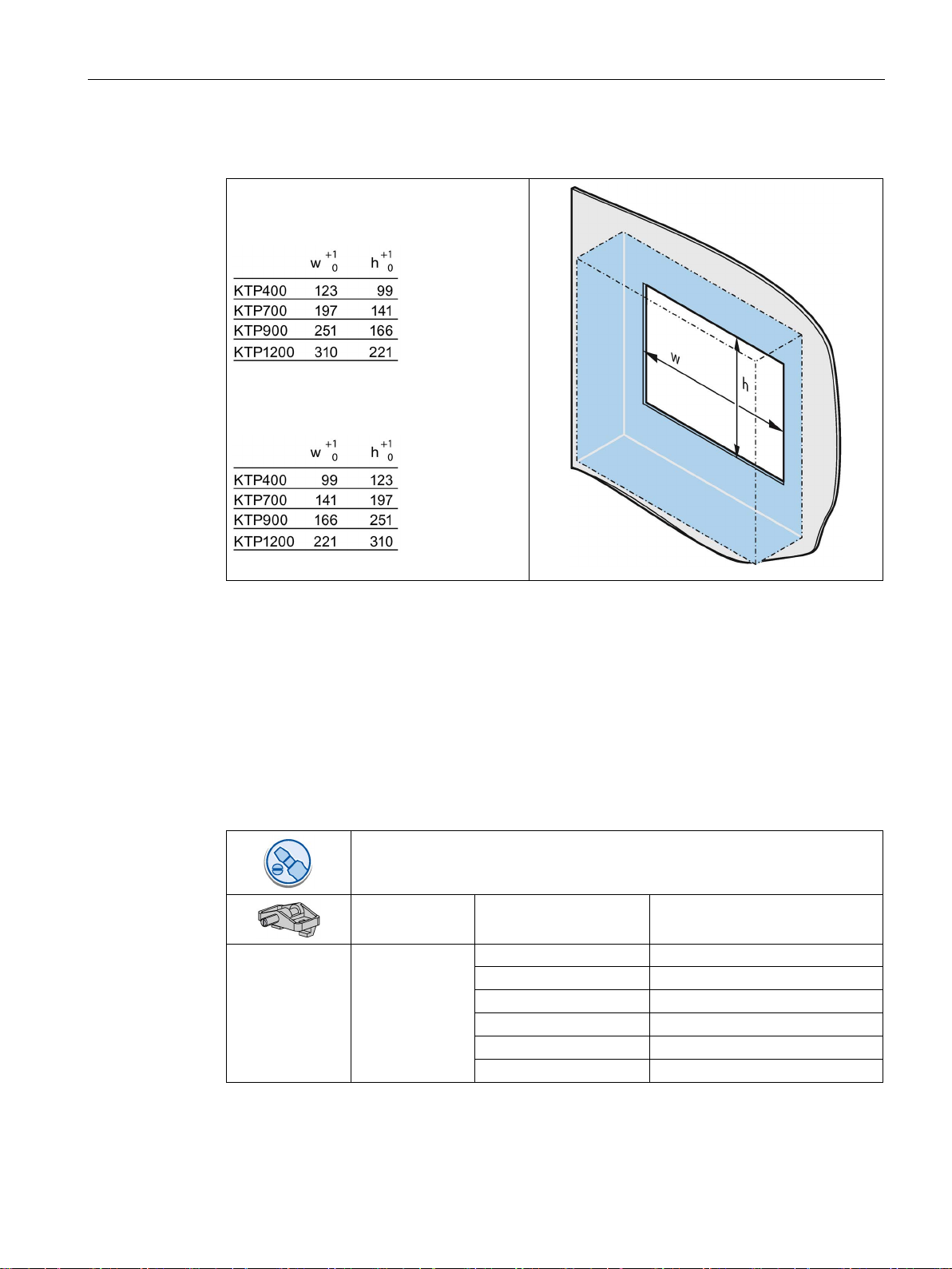
The following clearances are required around the HMI device to ensure sufficient selfventilation:
Required clearance around the
HMI devices.
All dimensions in mm
Basic Panels 2nd Generation
Operating Instructions, 10/2016, A5E33293231-AB
23

Mounting and connecting
3.1.5
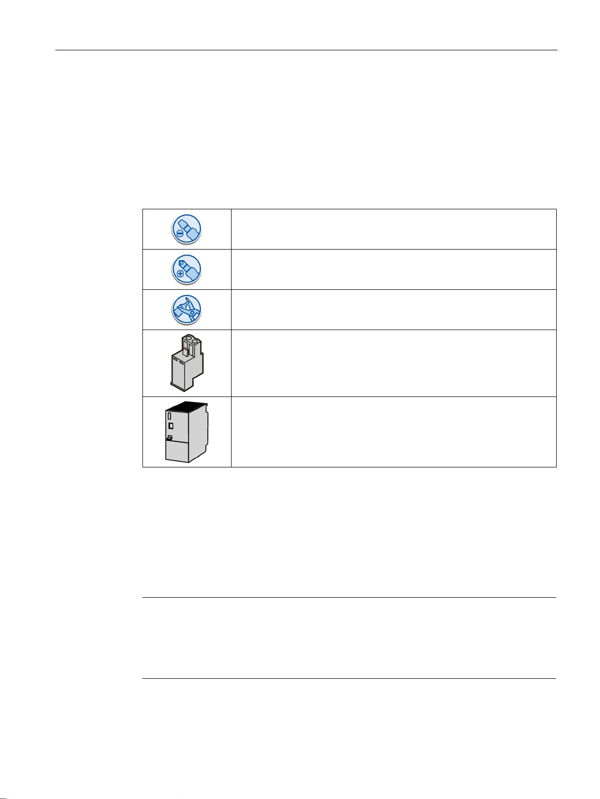
Making the mounting cutout
Note
Stability of the mounting cutout
The material in the area of the mounting
lasting and safe mounting of the HMI device.
To achieve the degrees of protection described below, it must be ensured that deformation
of the material cannot occur due to the force of the mounting clips
Degrees of protection
Mounting compatibility
Mounting cutout Basic Panel
Compatible with the mounting cutouts of the HMI device
KTP400 Basic
KTP400 Basic color PN
KTP700 Basic, KTP700 Basic DP
KTP600 Basic color PN; TP700 Comfort
KTP900 Basic
TP900 Comfort
KTP1200 Basic, KTP1200 Basic DP
TP1200 Comfort
3.1 Preparations
cutout must provide sufficient strength to guarantee
or operation of the device.
The degrees of protection of the HMI device can only be guaranteed if the following
requirements are met:
● Material thickness at the mounting cutout for a protection rating of IP65 or Front face only
Type 4X/Type 12 (indoor use only): 2 mm to 6 mm.
● Permitted deviation from plane at the mounting cutout: ≤ 0.5 mm
This condition must be met for the mounted HMI device.
● Permitted surface roughness in the area of the mounting seal: ≤ 120 µm (R
The mounting cutouts of the Basic panels are compatible with the mounting cutouts of the
following SIMATIC HMI devices:
120)
z
Basic Panels 2nd Generation
24 Operating Instructions, 10/2016, A5E33293231-AB
Mounting and connecting
Dimensions of the mounting cutout
All dimensions in mm
See also
3.2
Mounting the HMI device
Required tools and accessories
KTP400 Basic
4
KTP700 Basic
7
KTP700 Basic DP
7
KTP900 Basic
10
KTP1200 Basic
12
KTP1200 Basic DP
12
3.2 Mounting the HMI device
Dimensions of the mounting cutout for the
Basic HMI devices in horizontal mounting
position:
Dimensions of the mounting cutout for the
Basic HMI devices in vertical mounting
position:
Accessories (Page 15)
Slotted screwdriver, size 2
Mounting clips for HMI device Required quantity
Basic Panels 2nd Generation
Operating Instructions, 10/2016, A5E33293231-AB
25

Mounting and connecting
Inserting the HMI device
1.
2.
Securing the HMI device with mounting clips
1.
2.
3.
4.
3.2 Mounting the HMI device
Slide the labeling strip
into the device using
the guide, if available.
Insert the HMI device
into the mounting
cutout from the front.
Make sure that
protruding labeling
strips are not caught
between the mounting
cutout and HMI device.
If mounting clips and grub screws are
available separately in the accessory
kit, insert a grub screw into the
mounting clip bore hole and turn it
several times.
Place the first mounting clip into the
corresponding cutout.
Fasten the mounting clip with a size 2
screwdriver. The maximum permitted
torque is 0.2 Nm.
Repeat steps 1 to 3 for all mounting
clips required to secure your HMI
device.
Basic Panels 2nd Generation
26 Operating Instructions, 10/2016, A5E33293231-AB
Mounting and connecting
3.3
Connecting the HMI device
3.3.1
Connection sequence
Required tools and accessories
Procedure
Note
Strain relief
Contacts can be broken or wires
relief.
Provide adequate strain relief for all cables.
See also
3.3 Connecting the HMI device
Before you start connecting the HMI device, have the following tools and accessories at
hand:
Slotted screwdriver, size 2
Phillips screwdriver, size 3
Crimp pliers
Power supply connector
24 V DC with sufficient amperage.
See Technical specifications (Page 109)
Keep to the following sequence of tasks when connecting the HMI device:
1. Connecting the equipotential bonding circuit (Page 28)
2. Connecting the power supply (Page 29)
3. Connecting the configuration PC (Page 31)
4. Connecting the controller (Page 33)
Securing the cables (Page 38)
Basic Panels 2nd Generation
Operating Instructions, 10/2016, A5E33293231-AB
can be torn off if cables are not provided adequate strain
27

Mounting and connecting
3.3.2
Connecting the equipotential bonding circuit
Differences in electrical potential
General requirements for equipotential bonding
Note
Equipotential bonding conductor
Cable shielding is not suitable for equipotential bonding. Always use the prescribed
equipotential bonding conductors. The cross
must not be less than 16
installing MPI and PROFIBUS DP networks. The interface modules may otherwise be
damaged or destroyed.
3.3 Connecting the HMI device
Differences in electrical potential can develop between spatially separated system
components. Such electrical potential differences can lead to high equalizing currents on the
data cables and therefore to the destruction of their interfaces. Equalizing currents can
develop if the cable shielding is terminated at both ends and grounded to different system
parts.
Differences in potential may develop when a system is connected to different mains
supplies.
Differences in potential must be reduced by means of equipotential bonding conductors to
ensure trouble-free operation of the relevant components of the electronic system. The
following must therefore be observed when installing the equipotential bonding circuit:
● The effectiveness of equipotential bonding increases as the impedance of the
equipotential bonding conductor decreases or as its cross-section increases.
● If two system parts are interconnected by means of shielded data cables and their
shielding is bonded at both ends to the grounding/protective conductor, the impedance of
the additionally installed equipotential bonding conductor must not exceed 10% of the
shielding impedance.
● The cross-section of an equipotential bonding conductor must be capable of handling the
maximum equalizing current. The best practical results for equipotential bonding between
two cabinets have been achieved with a minimum conductor cross-section of 16 mm².
● Use equipotential bonding conductors made of copper or galvanized steel. Establish a
large surface contact between the equipotential bonding conductors and the
grounding/protective conductor and protect them from corrosion.
● Clamp the shielding of the data cable from the HMI device flush at the equipotential rail
using suitable cable clamps. The equipotential rail should be very close to the HMI
device.
● Route the equipotential bonding conductor and data cables in parallel and with minimum
clearance between them.
-section of the equipotential bonding conductor
mm². Always use cables with an adequate cross-section when
Basic Panels 2nd Generation
28 Operating Instructions, 10/2016, A5E33293231-AB
Mounting and connecting
Procedure
1.
2.
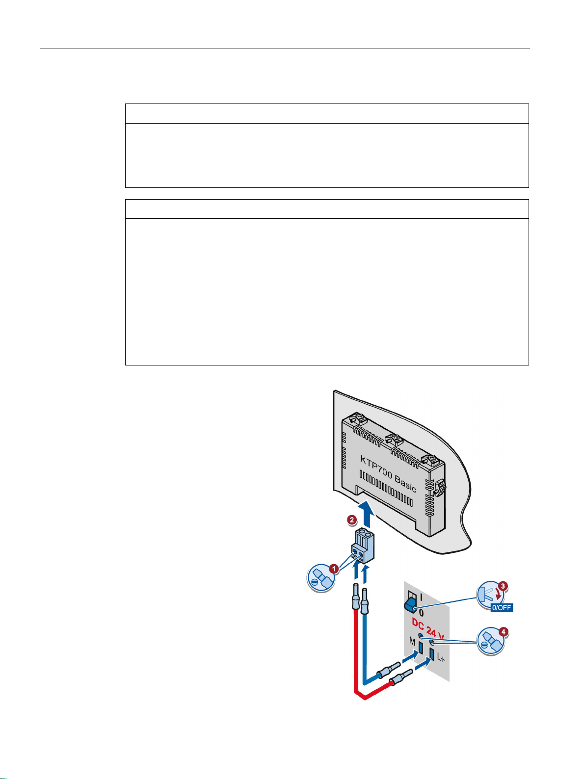
3.3.3
Connecting the power supply
Stripping the cable
Use power supply cables with a
maximum cross
1. Strip the ends of two power supply
2.
3.
3.3 Connecting the HMI device
Interconnect the functional earth
connection of the HMI device with
an equipotential bonding conductor,
cross-section 4 mm
Connect the equipotential bonding
conductor to the equipotential
bonding rail.
2
.
cables to a length of 6 mm.
Attach cable sleeves to the bare
cable ends.
Basic Panels 2nd Generation
Operating Instructions, 10/2016, A5E33293231-AB
Install the end sleeves on the
cable ends using the crimp pliers.
-section of 1.5 mm2.
29
Mounting and connecting
Procedure
NOTICE
24 V DC only
NOTICE
Safe electrical isolation
1.
2.
3.
4.
3.3 Connecting the HMI device
An incorrectly dimensioned power supply can destroy the HMI device.
Use a 24 V DC power supply with adequate amperage; see Technical specifications
(Page 109).
For the 24 V DC supply, use only power supply units with safe electrical isolation in
accordance with IEC 60364-4-41 or HD 384.04.41 (VDE 0100, Part 410), e.g. conforming
to the SELV/PELV standard.
The supply voltage must be within the specified voltage range. Otherwise, malfunctions at
the HMI device cannot be ruled out.
Applies to non-isolated system configurations:
Connect the GND 24 V connection from the 24 V power supply output to equipotential
bonding for uniform reference potential. You should always select a central point of
termination.
Connect the two power supply
cables to the power supply
connector as shown. Secure the
power supply cables with a slotted
screwdriver.
Connect the power supply
connector to the HMI device.
Check the correct polarity of the
cables using the interface marking
on the back of the HMI device.
Switch off the power supply.
Insert the two remaining cable
ends into the power supply
terminals and secure them with
the slotted screwdriver.
Ensure correct polarity.
Basic Panels 2nd Generation
30 Operating Instructions, 10/2016, A5E33293231-AB
 Loading...