

Siemens SIMATIC HMI IRD400 Operating Instructions Manual

___________________
___________________
___________________
___________________
___________________
___________________
___________________
___________________
___________________
SIMATIC HMI
HMI device
IRD400
Operating Instructions
05/2018
A5E36790512
Preface
Overview
1
Safety instructions
2
Installing and connecting the
display unit
3
Operating the display unit
4
Configuring the display unit
5
Maintenance and repairs
6
Technical specifications
7
Appendix
A
-AC
Siemens AG
Division Digital Factory
Postfach 48 48
90026 NÜRNBERG
GERMANY
A5E36790512-AC
Ⓟ
Copyright © Siemens AG 2018.
All rights reserved
Legal information
Warning notice system
DANGER
indicates that death or severe personal injury will result if proper precautions are not taken.
WARNING
indicates that death or severe personal injury may result if proper precautions are not taken.
CAUTION
indicates that minor personal injury can result if proper precautions are not taken.
NOTICE
indicates that property damage can result if proper precautions are not taken.
Qualified Personnel
personnel qualified
Proper use of Siemens products
WARNING
Siemens products may only be used for the applications described in the catalog and in the relevant technical
maintenance are required to ensure that the products operate safely and without any problems. The permissible
ambient conditions must be complied with. The information in the relevant documentation must be observed.
Trademarks
Disclaimer of Liability
This manual contains notices you have to observe in order to ensure your personal safety, as well as to prevent
damage to property. The notices referring to your personal safety are highlighted in the manual by a safety alert
symbol, notices referring only to property damage have no safety alert symbol. These notices shown below are
graded according to the degree of danger.
If more than one degree of danger is present, the warning notice representing the highest degree of danger will
be used. A notice warning of injury to persons with a safety alert symbol may also include a warning relating to
property damage.
The product/system described in this documentation may be operated only by
task in accordance with the relevant documentation, in particular its warning notices and safety instructions.
Qualified personnel are those who, based on their training and experience, are capable of identifying risks and
avoiding potential hazards when working with these products/systems.
Note the following:
documentation. If products and components from other manufacturers are used, these must be recommended
or approved by Siemens. Proper transport, storage, installation, assembly, commissioning, operation and
All names identified by ® are registered trademarks of Siemens AG. The remaining trademarks in this publication
may be trademarks whose use by third parties for their own purposes could violate the rights of the owner.
We have reviewed the contents of this publication to ensure consistency with the hardware and software
described. Since variance cannot be precluded entirely, we cannot guarantee full consistency. However, the
information in this publication is reviewed regularly and any necessary corrections are included in subsequent
editions.
for the specific
05/2018 Subject to change

Preface
Purpose of the operating instructions
Scope
Note
Note:
• You are also going to need this document whenever the system is recommissioned. Keep
•
Knowledge required
Style conventions
Notation
Scope
command
These operating instructions provides information relating to the place of use, transport,
storage, mounting, use and maintenance of the device.
These operating instructions are intended for:
● Commissioning engineers
● Operators
● Maintenance personnel
This document applies to the display unit "SIMATIC HMI IRD400" with the article number
6ES7292-0AA50-1AA0.
Submit all of these documents to a future owner of the device.
General knowledge in the fields of electrical engineering, automation technology and
process communication is prerequisite for comprehension of this documentation.
"Add screen"
"File > Edit" Operational sequences, e.g, menu command, shortcut menu
this and supplementary documentation in a safe place for the entire life cycle of the
device.
• Terminology for the user interface, e.g. dialog name, tab, but-
ton, menu command
• Necessary entries, e.g. limit value, tag value
• Path information
IRD400
Operating Instructions, 05/2018, A5E36790512-AC
3
Preface
Note
A note contains important information about the product described in the document and its
handling, or a specific section of the document to which you should pay particular attention.
Naming conventions
Term
Applies to
Display unit
SIMATIC HMI IRD400
Device
Display unit
Figures
Please observe notes labeled as follows:
Control cabinet
• Installation cabinet
• Enclosure
• Terminal box
• Console
• Switchboard
This document contains illustrations of the described devices. The illustrations may deviate
from the particularities of the delivered device.
IRD400
4 Operating Instructions, 05/2018, A5E36790512-AC

Table of contents
Preface ........................................................................................................................................ 3
1 Overview ...................................................................................................................................... 7
2 Safety instructions ....................................................................................................................... 10
3 Installing and connecting the display unit ........................................................................................ 13
4 Operating the display unit ............................................................................................................. 26
5 Configuring the display unit ........................................................................................................... 29
6 Maintenance and repairs .............................................................................................................. 40
1.1 Product overview ................................................................................................................. 7
1.2 Scope of delivery ................................................................................................................. 7
1.3 Design of the display unit ..................................................................................................... 8
1.4 Accessories ......................................................................................................................... 9
2.1 Industrial Security .............................................................................................................. 12
3.1 Preparing for mounting ...................................................................................................... 13
3.1.1 Checking the package contents ......................................................................................... 13
3.1.2 Permitted mounting positions ............................................................................................. 14
3.1.3 Installation location and clearance ..................................................................................... 16
3.2 Installing the display unit.................................................................................................... 18
3.3 Connecting the display unit ................................................................................................ 19
3.3.1 Connection information ...................................................................................................... 19
3.3.2 Connecting functional ground ............................................................................................ 20
3.3.3 Connecting the Power Supply ............................................................................................ 22
3.3.4 Connecting the PLC .......................................................................................................... 24
3.3.5 Connecting digital inputs/outputs ....................................................................................... 25
3.3.6 Securing the cables ........................................................................................................... 25
5.1 PROFINET modules .......................................................................................................... 29
5.2 Configuring in the TIA Portal .............................................................................................. 30
5.3 Slot 1 - IR-RC module (IR remote control).......................................................................... 33
5.4 Slot 2 - DISPLAY module (7-segment display and LEDs) ................................................... 34
5.5 Slot 3 - Digital port module (8 x DI/DO) .............................................................................. 36
5.6 Slot 4 - IR-P2P module ("IR-P2P" operating mode) ............................................................ 37
5.7 Slot 5 - Control module (operating mode) .......................................................................... 38
6.1 Recycling and disposal ...................................................................................................... 40
IRD400
Operating Instructions, 05/2018, A5E36790512-AC
5

Table of contents
7 Technical specifications ............................................................................................................... 41
A Appendix ................................................................................................................................... 51
Index ......................................................................................................................................... 53
7.1 Certificates and approvals ..................................................................................................41
7.2 Notes about usage .............................................................................................................42
7.3 Electromagnetic compatibility .............................................................................................42
7.4 Ambient conditions .............................................................................................................44
7.4.1 Transportation and storage requirements ...........................................................................44
7.4.2 Operational requirements ...................................................................................................45
7.4.3 Tests for ambient conditions ...............................................................................................46
7.5 Dimensional diagram ..........................................................................................................47
7.6 Technical specifications ......................................................................................................47
7.7 Interface description ...........................................................................................................49
7.7.1 Power supply .....................................................................................................................49
7.7.2 RS 232 interface (X30) .......................................................................................................49
7.7.3 PROFINET .........................................................................................................................50
7.7.4 Digital inputs/outputs ..........................................................................................................50
A.1 Technical support ...............................................................................................................51
A.2 Abbreviations .....................................................................................................................52
IRD400
6 Operating Instructions, 05/2018, A5E36790512-AC
1
1.1
Product overview
1.2
Scope of delivery
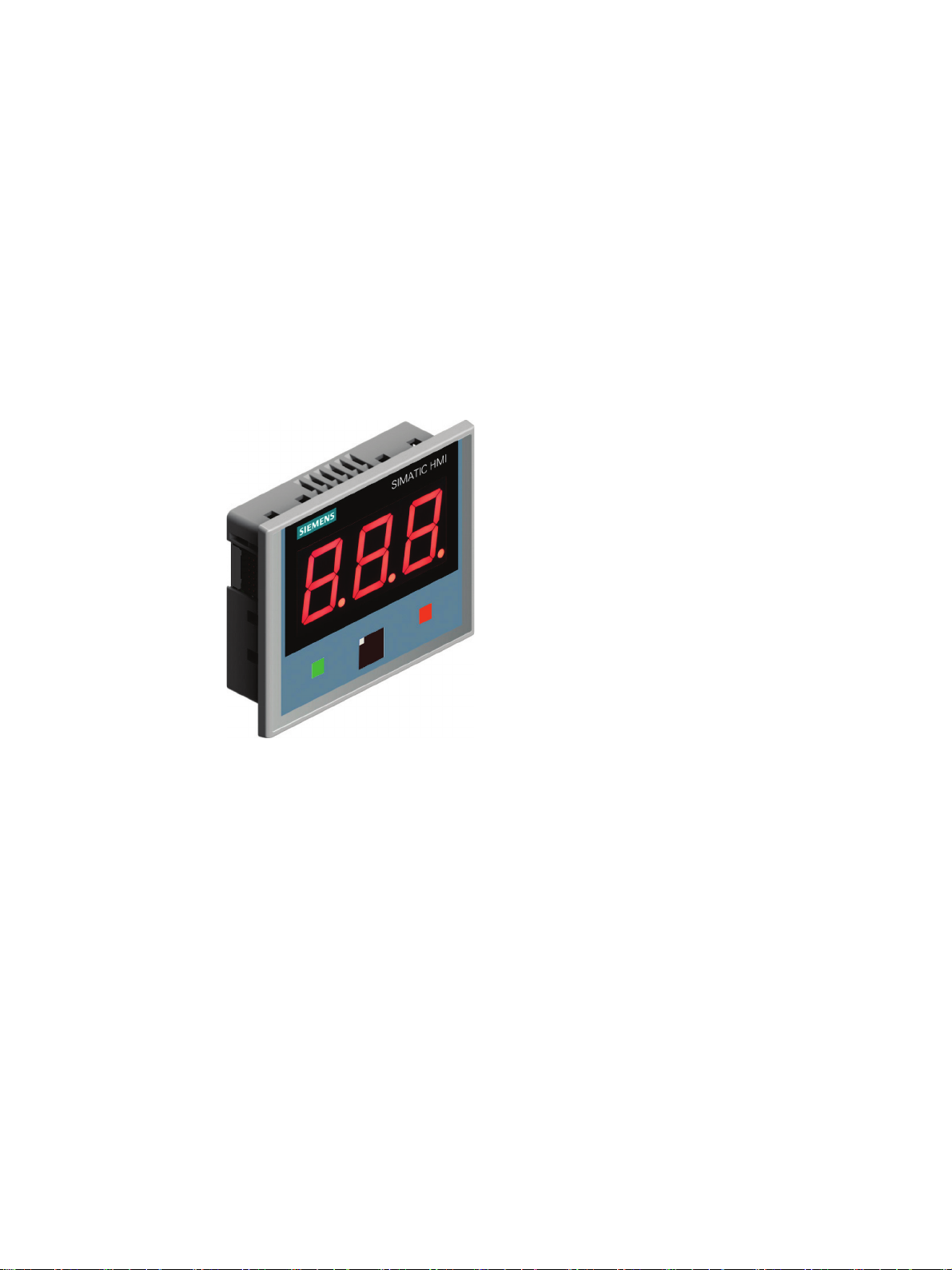
The display unit is used to display data which is sent by a controller. Digits or symbols can
be shown in the display. The status of the controller, for example, can be signaled via the
LEDs. In addition, two controllers which are each connected to a IRD400 display unit can
communicate via the display units.
The display ensures legibility up to a distance of 10 m. You can use the integrated dimming
function to adjust the display to the ambient light conditions.
The display unit has an infrared transmitter/receiver module which is tuned to the IR remote
control with the article number 6ES7292-0CA50-0AA0 and can communicate with a display
unit of the same design. The display unit can be used with and without remote control. You
can use the IR remote control to adjust the brightness of the display on the display unit and
transmit signals to the controller via the display unit.
The display unit is configured with STEP 7 (TIA Portal).
IRD400
Operating Instructions, 05/2018, A5E36790512-AC
The scope of delivery of the display unit includes:
● 1 × display unit
● 1 x accessory pack with the following contents:
– 4 mounting clips
– 4 threaded pins for the mounting clips
– 1 mains terminal for the power supply
– 1 plug connector, 12-pin
7
Overview
1.3
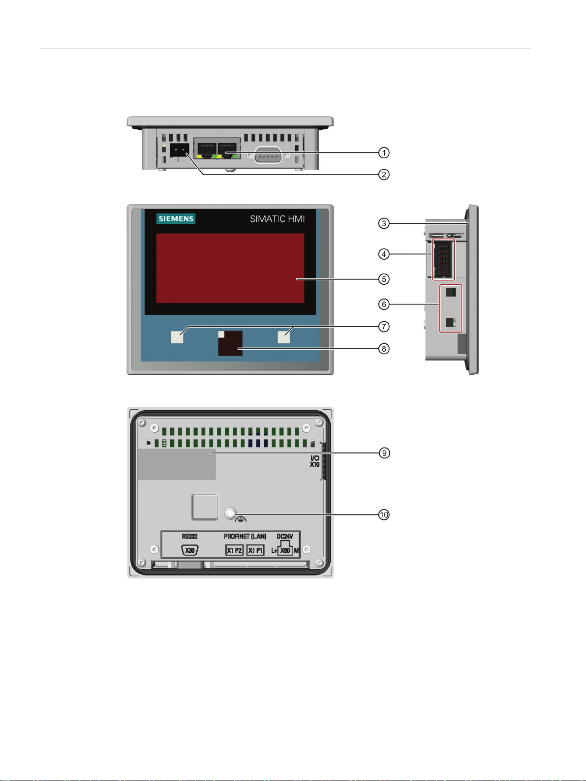
Design of the display unit
①
PROFINET ports X1 P1 and X1 P2
⑥
Recesses for a mounting clip
②
⑦
displaying the operating state
③
⑧
LED
④
I/O interface X10, digital inputs/outputs
⑨
Rating plate
⑤
Display with three 7-segment displays
⑩
Connection for functional earthing
1.3 Design of the display unit
Power supply connector X80
Mounting seal
The RS 232 interface X30 is deactivated.
IRD400
8 Operating Instructions, 05/2018, A5E36790512-AC
"Green" and "red" LEDs, for example for
IR transmitter/receiver module with "blue"

Overview
Display and LEDs
PROFINET ports and digital inputs/outputs
1.4
Accessories
1.4 Accessories
The LED contains three 7-segment displays, each with a decimal point.
The response of the three 7-segment displays and LEDs is defined via the configuration.
The display unit communicates with the controller via PROFINET. The response of the digital
inputs/outputs (pins 1...8) of the I/O interface X10 is defined via the configuration of the slots
in HW Config (TIA Portal) and is freely-programmable.
Accessories for the display unit:
● IR remote control
The IR remote control represents the input device for the display unit. The article number
is 6ES7292-0CA50-0AA0.
Accessories can be found on the Internet (https://mall.industry.siemens.com
).
IRD400
Operating Instructions, 05/2018, A5E36790512-AC
9
2
WARNING
Injury or material damage
Safety during commissioning and operation
WARNING
Installation/use as intended
Safety when working in and on electrical systems
You risk the development of danger sources and deactivation of safety functions if you
neglect the safety and handling instructions provided in this document. This can result in
personal injuries or material damage.
Strictly adhere to the safety and handling instructions.
Always adhere to the safety instructions and accident prevention regulations for the
respective application, independent of the safety instructions provided in this document.
It is strictly forbidden to commission the device before compliance with Machinery Directive
2006/42/E has been verified for the machine to be operated with this device.
Verify before commissioning that the provisions of Directive 2006/42/EC are fulfilled.
Only authorized persons are allowed to work in or on electrical equipment. The following
safety regulations for prevention of electrical shock are valid in Germany:
1. Isolation of the system from power
2. Securing the system against restart
3. Verification of isolation from power at all poles
4. Grounding and shorting the system
5. Covering or fencing off adjacent live parts
IRD400
10 Operating Instructions, 05/2018, A5E36790512-AC
Safety instructions
Note
The safety regulations must be
carried out on electrical systems. The safety regulations must be applied in reverse order on
completion of all tasks on the electrical system.
Infrared interference signal
WARNING
Malfunctions with IR interference signal possible
Strong high-frequency radiation
NOTICE
Observe immunity to RF radiation
These safety regulations are based on DIN VDE 0105.
applied in the aforementioned order before any work is
Identify the electrical system in accordance with valid safety regulations when working on
this system.
Observe the valid safety regulations of the respective country.
The display unit receives all infrared signals of their spectrum within their sensing range.
Interference signals can cause unwanted commands to be sent to the controller.
Unintentional reaction of the plant as well as personal injury or property damage can result.
Note:
• Do not operate any infrared signal sources except the permitted remote control in the
entire receiving range of the display unit Only the remote control "IR-RC" with article
number 6ES7292-0CA50-0AA0 is permitted.
• Take appropriate measures to prevent interference by other sources within the spectrum
and reception range of the display unit. Read the information in the technical
specifications.
The device has an increased immunity to RF radiation according to the specifications on
electromagnetic compatibility in the technical specifications.
Radiation exposure in excess of the specified immunity limits can impair device functions,
result in malfunctions and therefore injuries or damages.
Read the information on immunity to RF radiation in the technical specifications.
IRD400
Operating Instructions, 05/2018, A5E36790512-AC
11
Safety instructions
Warranty
ESD
2.1
Industrial Security
Industrial Security
2.1 Industrial Security
Prerequisites for trouble-free and safe operation of the device:
● Proper transportation and storage
● Proper mounting and wiring
● Proper operation and repairs
Non-compliance with these regulations shall render the device warranty void.
An ESD (Electrostatically Sensitive Device) is equipped with electronic components. Due to
their design, electronic components are highly sensitive to overvoltage and electrostatic
discharge. Observer the regulations governing the handling of ESD components.
Siemens provides products and solutions with industrial security functions that support the
secure operation of plants, systems, machines and networks.
In order to protect plants, systems, machines and networks against cyber threats, it is
necessary to implement – and continuously maintain – a holistic, state-of-the-art industrial
security concept. Siemens’ products and solutions only form one element of such a concept.
Siemens’ products and solutions only form one element of such a concept.
Customer is responsible to prevent unauthorized access to its plants, systems, machines
and networks. Systems, machines and components should only be connected to the
enterprise network or the internet if and to the extent necessary and with appropriate security
measures (e.g. use of firewalls and network segmentation) in place.
Additionally, Siemens’ guidance on appropriate security measures should be taken into
account. For more information about industrial security, please visit
(http://www.siemens.com/industrialsecurity
Siemens’ products and solutions undergo continuous development to make them more
secure. Siemens strongly recommends to apply product updates as soon as available and to
always use the latest product versions. Use of product versions that are no longer supported,
and failure to apply latest updates may increase customer’s exposure to cyber threats.
To stay informed about product updates, subscribe to the Siemens Industrial Security RSS
Feed under (http://www.siemens.com/industrialsecurity
).
).
IRD400
12 Operating Instructions, 05/2018, A5E36790512-AC

3
3.1
Preparing for mounting
3.1.1
Checking the package contents
Note
Damaged parts
Do not install parts damaged during shipment. In the case of damaged parts, contact your
Siemens representative.
Check the package content for visible signs of transport damage and for completeness.
The package content is described in section Scope of delivery (Page 7).
Keep the provided documentation in a safe place. The documentation is part of the HMI
device and is required for subsequent commissioning.
IRD400
Operating Instructions, 05/2018, A5E36790512-AC
13
Installing and connecting the display unit
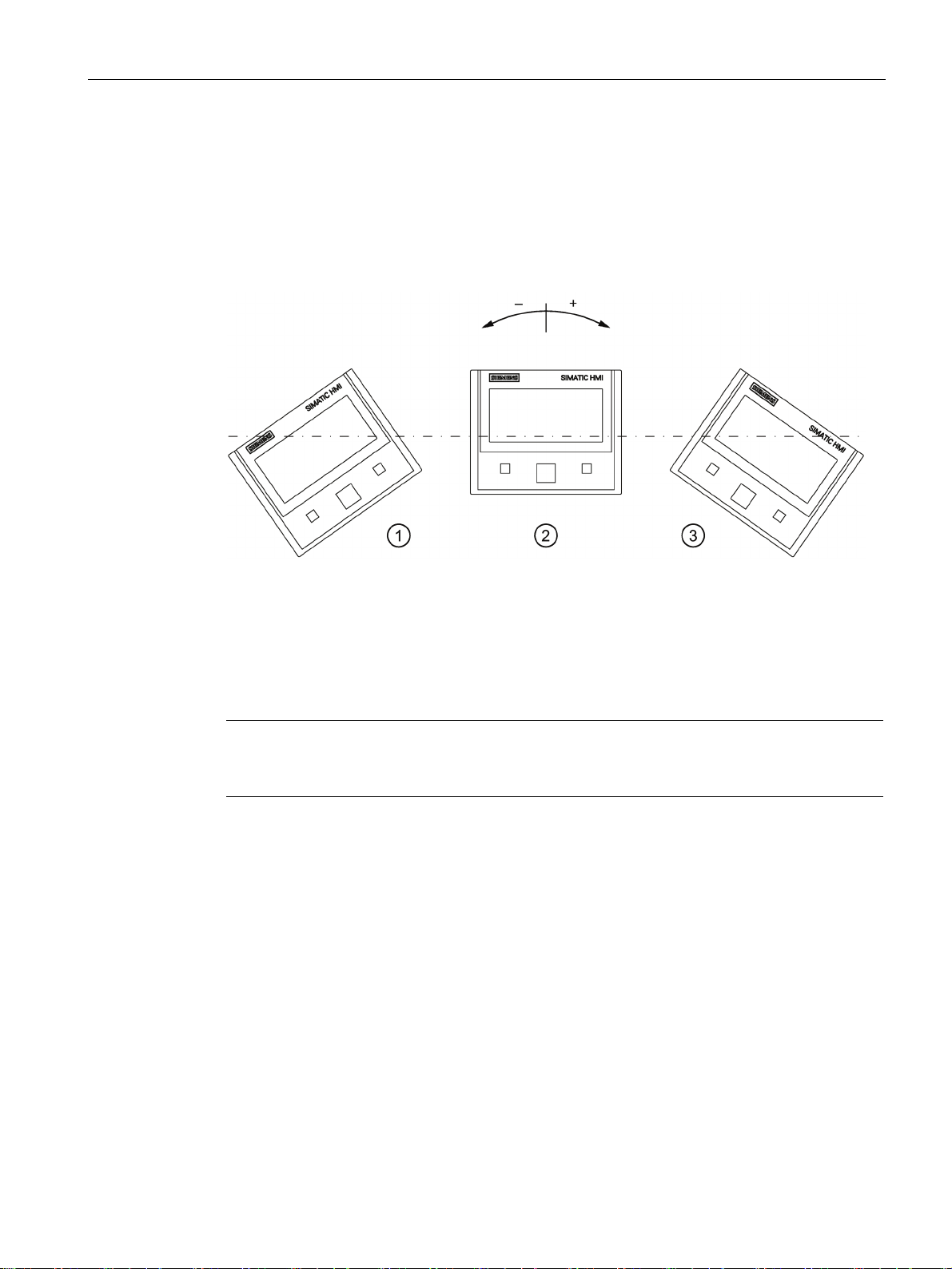
3.1.2
Permitted mounting positions
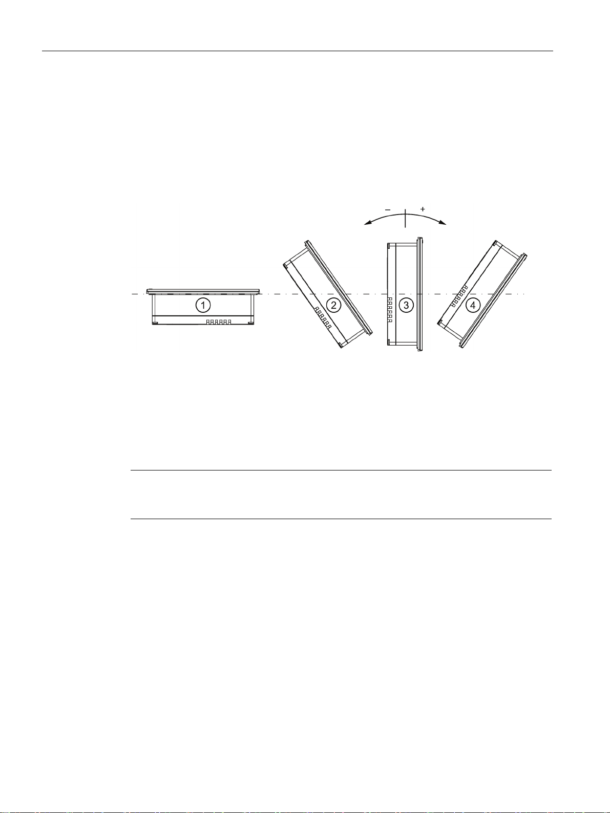
Mounting position
Mounting position
Deviation from the perpendicular axis
Temperature
①
Horizontal
-90°
0 ... 50 °C
②
Inclined
≥ –35°
0 ... 60 °C
③
Vertical
0°
0 ... 60 °C
④
Inclined
≤ 35°
0 ... 60 °C
Note
You risk damage to the display unit if operating it outside the approved ambient temperature
limits. The approvals and warranty for the display unit are rendered void in this case.
3.1 Preparing for mounting
The display unit is approved for operation in horizontal and inclined mounting position in
stationary and mobile control cubicles.
The following lateral installation angles are permitted:
The display unit is quipped with venting slots for heat convection into the control cabinet
where thermal energy is dissipated on the panels of the control cabinet.
IRD400
14 Operating Instructions, 05/2018, A5E36790512-AC
Installing and connecting the display unit
Mobile operation
Position
Deviation from the perpendicular axis
①
Tilted
≥ –35°
②
Vertical
0°
③ Tilted
≤ 35°
Note
Please note that the vertical position
period of time.
3.1 Preparing for mounting
If you operate the device in a mobile system, for example in an electrical monorail system,
then in addition to the lateral installation angle, the permitted tilt of the front of the device
must be taken into consideration.
The following angles of inclination are permitted for a short time for the display unit during
movement:
Inclinations may occur, for example, if the display unit is mounted to a conveying device that
services several levels of the plant.
② for mobile use may only be exceeded for a short
IRD400
Operating Instructions, 05/2018, A5E36790512-AC
15
Installing and connecting the display unit
3.1.3
Installation location and clearance
Selecting installation location
NOTICE
Installation location
Observe the permissible ambient conditions when selecting the installation location.
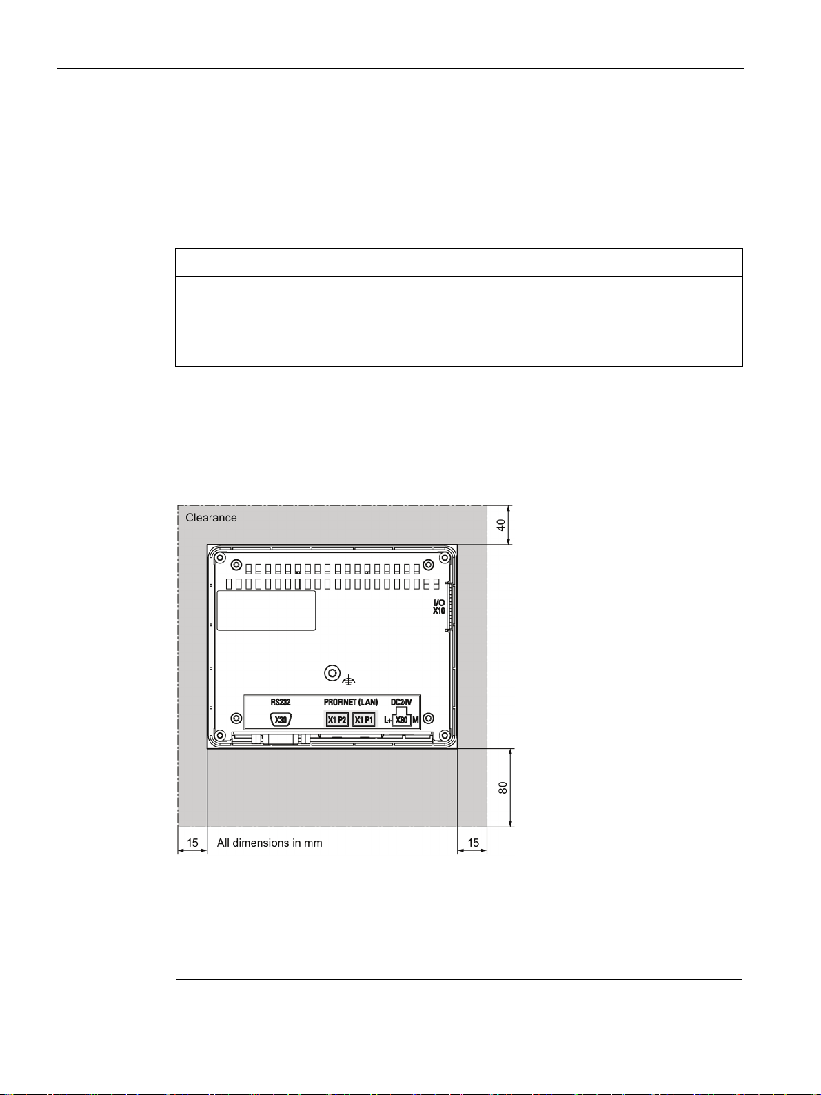
Clearance
Note
Additional clearance for connectors and cables
Take into consideration additional clearance due to the type of connector used and the
permissible bending radii of the connecting cables.
3.1 Preparing for mounting
The display unit is designed for installation in a control cabinets. The display unit is installed
in landscape format.
Non-compliance with permissible ambient conditions at the installation location may lead to
malfunctions.
When selecting the mounting location for the display unit, ensure that sufficient heat
convection is possible. Avoid installation of heat generating equipment directly underneath
the display unit.
The following clearance is required for ventilation of the display unit:
10 mm clearance at the rear side of the device.
IRD400
16 Operating Instructions, 05/2018, A5E36790512-AC
Installing and connecting the display unit
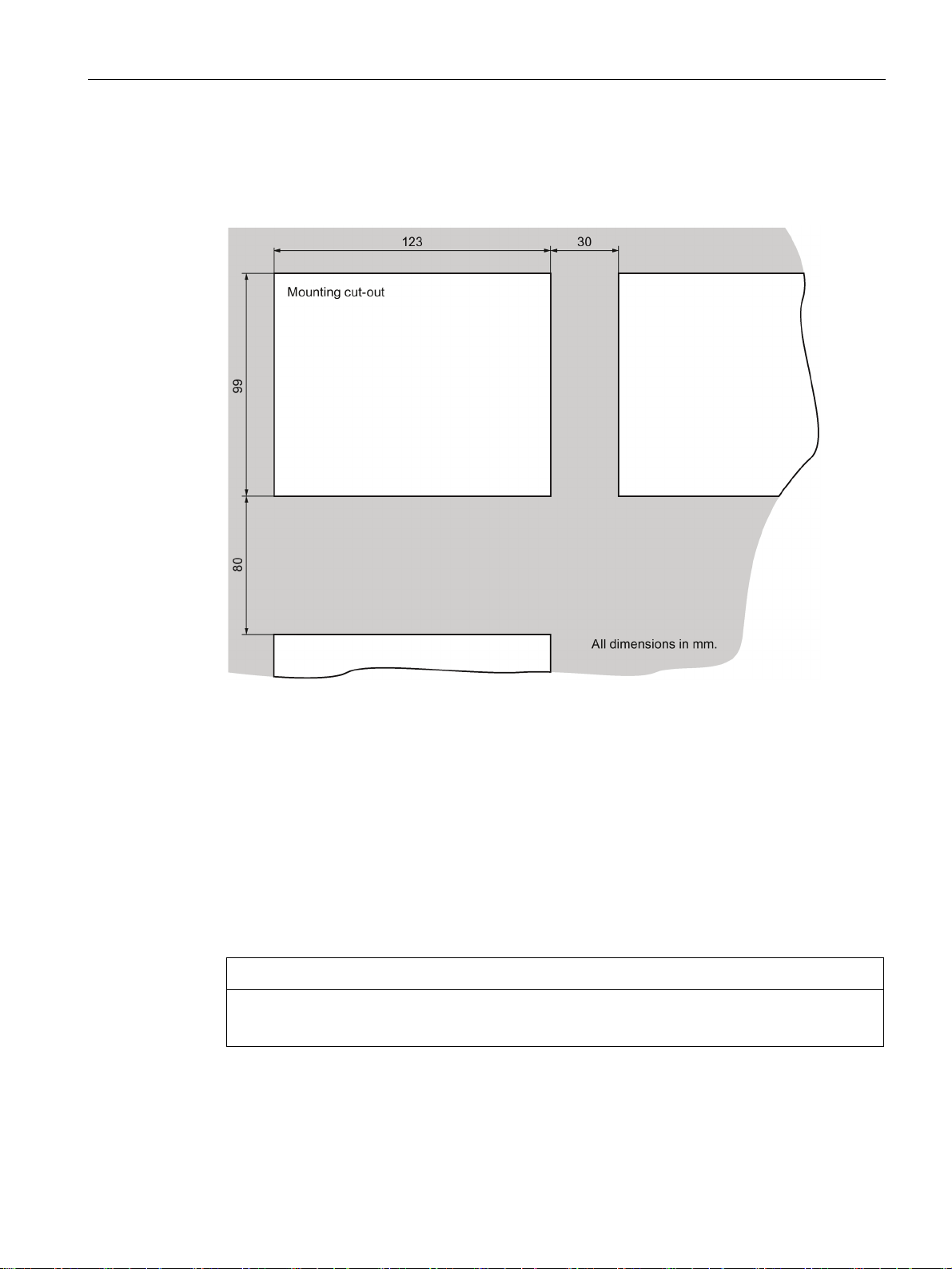
Dimensions of the mounting cut-out
Configuration of the mounting cut-out
NOTICE
Operation in the scope of UL508
3.1 Preparing for mounting
The following figure shows the dimensions of the mounting cut-out and the clearances to be
observed when mounting several devices in a horizontal or vertical arrangement.
The following conditions must be met to ensure the degree of protection:
● The material at the mounting cut-out must be resistant to distortion.
● Material thickness at the mounting cut-out for IP65 degree of protection, or for
enclosure type 4X/type 12 (indoor use only): 2 mm bis 6 mm
● Permitted deviation from plane at the mounting cutout: ≤ 0.5 mm
This condition must be fulfilled for the mounted HMI device.
● Permitted surface roughness in the area of the mounting seal: ≤ 120 µm (R
For use on a flat surface of a Type 1 (indoor use only) Enclosure.
120)
z
IRD400
Operating Instructions, 05/2018, A5E36790512-AC
17
 Loading...