

Page 1

_
_
_
_
_
_
_
_
_
_
_
_
_
_
_
_
_
_
_
_
_
_
Basic Panels
SIMATIC HMI
HMI devices
Basic Panels
Operating Instructions
_________________
Preface
_________________
Overview
_________________
Safety instructions
_________________
Mounting and connecting
_________________
Operating the device
_________________
Configuring the HMI device
_________________
Commissioning a project
_________________
Maintenance and care
_________________
Technical specifications
_________________
Technical Support
_________________
Abbreviations
1
2
3
4
5
6
7
8
A
B
04/2012
A5E02421799-03
Page 2
Legal information
Legal information
Warning notice system
This manual contains notices you have to observe in order to ensure your personal safety, as well as to prevent
damage to property. The notices referring to your personal safety are highlighted in the manual by a safety alert
symbol, notices referring only to property damage have no safety alert symbol. These notices shown below are
graded according to the degree of danger.
DANGER
indicates that death or severe personal injury will result if proper precautions are not taken.
WARNING
indicates that death or severe personal injury may result if proper precautions are not taken.
CAUTION
with a safety alert symbol, indicates that minor personal injury can result if proper precautions are not taken.
CAUTION
without a safety alert symbol, indicates that property damage can result if proper precautions are not taken.
NOTICE
indicates that an unintended result or situation can occur if the relevant information is not taken into account.
If more than one degree of danger is present, the warning notice representing the highest degree of danger will
be used. A notice warning of injury to persons with a safety alert symbol may also include a warning relating to
property damage.
Qualified Personnel
The product/system described in this documentation may be operated only by personnel qualified for the specific
task in accordance with the relevant documentation, in particular its warning notices and safety instructions.
Qualified personnel are those who, based on their training and experience, are capable of identifying risks and
avoiding potential hazards when working with these products/systems.
Proper use of Siemens products
Note the following:
WARNING
Siemens products may only be used for the applications described in the catalog and in the relevant technical
documentation. If products and components from other manufacturers are used, these must be recommended
or approved by Siemens. Proper transport, storage, installation, assembly, commissioning, operation and
maintenance are required to ensure that the products operate safely and without any problems. The permissible
ambient conditions must be complied with. The information in the relevant documentation must be observed.
Trademarks
All names identified by ® are registered trademarks of Siemens AG. The remaining trademarks in this publication
may be trademarks whose use by third parties for their own purposes could violate the rights of the owner.
Disclaimer of Liability
We have reviewed the contents of this publication to ensure consistency with the hardware and software
described. Since variance cannot be precluded entirely, we cannot guarantee full consistency. However, the
information in this publication is reviewed regularly and any necessary corrections are included in subsequent
editions.
Siemens AG
Industry Sector
Postfach 48 48
90026 NÜRNBERG
GERMANY
A5E02421799-03
Ⓟ 04/2012 Technical data subject to change
Copyright © Siemens AG 2012.
All rights reserved
Page 3

Preface
Purpose of the operating instructions
These operating instructions provide information based on the requirements defined by
IEC 62079 for documentation. This information relates to the HMI device, its storage,
transportation, place of use, installation, use and maintenance.
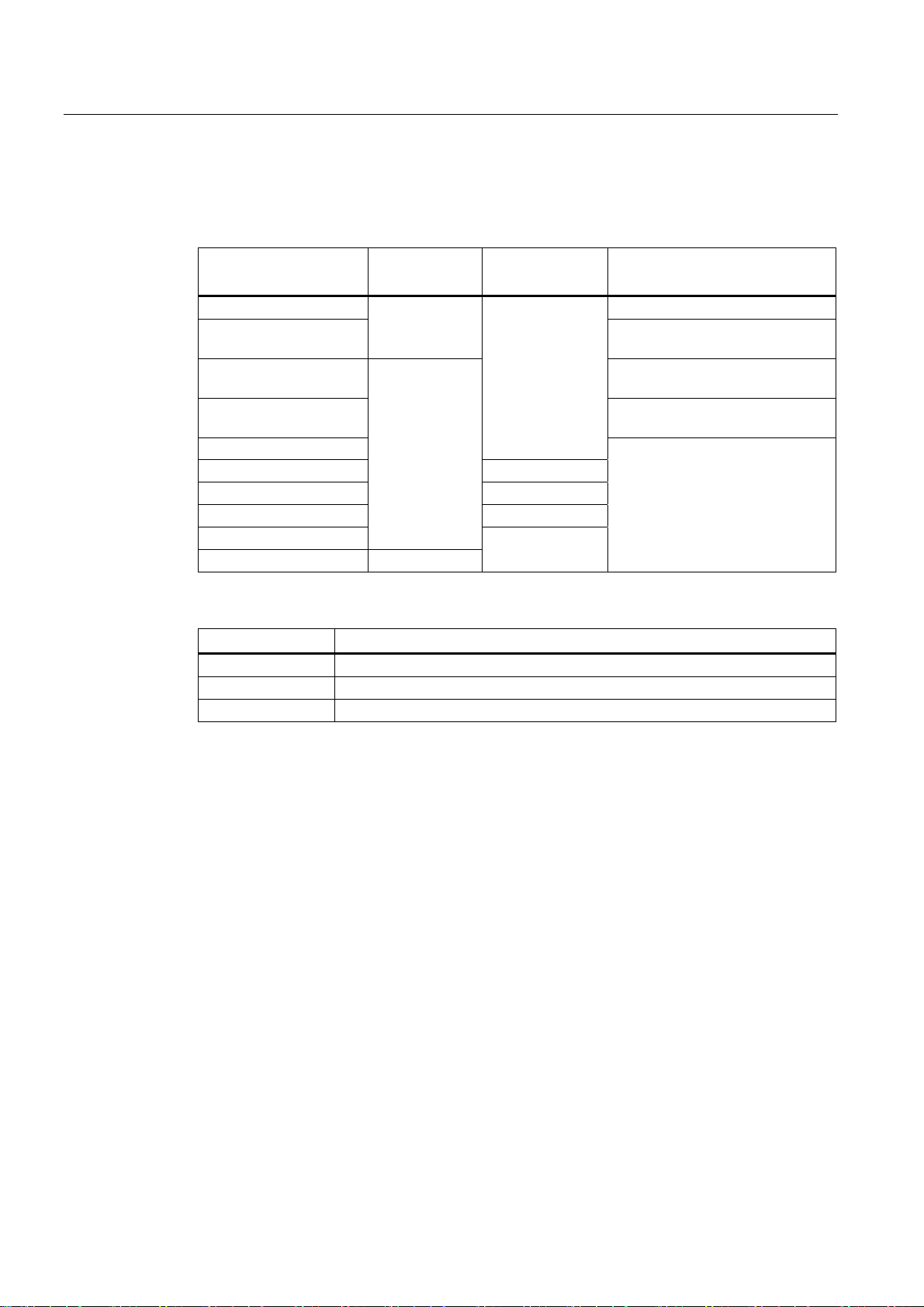
These operating instructions are intended for a variety of target groups. The following table
shows the chapters of these operating instructions that are of particular importance for the
respective target group.
Target group Chapter
All "Safety instructions"
Operators
The operator operates and monitors the system
during the process control phase.
Commissioning engineers
The commissioning engineer integrates the HMI
device into the system and ensures the operating
capability of the HMI device for the process control
phase.
Service technicians
Service technicians rectify faults that occur during
the process control phase.
Maintenance technicians
Maintenance technicians carry out servicing and
maintenance work during the process control
phase.
"Overview"
"Operating a project"
All chapters.
Depending on the use of the HMI device,
certain chapters may not be of relevance to the
commissioning engineer, e.g. the section
"Maintenance and servicing."
All chapters.
Depending on the use of the HMI device,
certain chapters may not be of relevance to the
service technicians, e.g. the section
"Maintenance and servicing."
Maintenance and care
The information system of WinCC flexible and WinCC contains further additional informaiton.
The information system is integrated as online help in WinCC flexible and WinCC and
contains instructions, examples and reference information in electronic form.
Basic Panels
Operating Instructions, 04/2012, A5E02421799-03
3
Page 4
Preface
Scope
These operating instructions are valid for all SIMATIC HMI Basic Panels. The following
naming conventions apply:
Device designation
SIMATIC HMI
KP300 Basic mono PN WinCC (TIA Portal) as of V11
KP400 Basic color PN
KTP400 Basic mono PN WinCC flexible and WinCC (TIA
KTP400 Basic color PN WinCC (TIA Portal) as of V11 SP2
KTP600 Basic mono PN
KTP600 Basic color DP Basic Panel DP
KTP600 Basic color PN Basic Panel PN
KTP1000 Basic color DP Basic Panel DP
KTP1000 Basic color PN
TP1500 Basic color PN Touch device
Device type Interface type Can be configured with
Keyboard unit
Touch device
with function
keys
Basic Panel PN
WinCC (TIA Portal) as of V11 SP2
Update 2 with HSP Basic 4" color
Portal) as of V11
Update 2 with HSP Basic 4" color
WinCC flexible and WinCC (TIA
Portal) as of V11
Basic Panel PN
In addition, the following collective designations are also used in these operating
instructions:
Designation Covers the HMI devices
KTP400 Basic KTP400 Basic mono PN, KTP400 Basic color PN
KTP600 Basic KTP600 Basic mono PN, KTP600 Basic color DP, KTP600 Basic color PN
KTP1000 KTP1000 Basic color DP, KTP1000 Basic color PN
Basic knowledge required
Knowledge of automation technology and process communication is necessary to
understand the operating instructions.
An understanding of the use of computers and operating systems is also required.
Basic Panels
4 Operating Instructions, 04/2012, A5E02421799-03
Page 5
Preface
Illustrations and text highlighting
This manual contains illustrations of the described devices. The illustrations may deviate
from the supplied device in certain details.
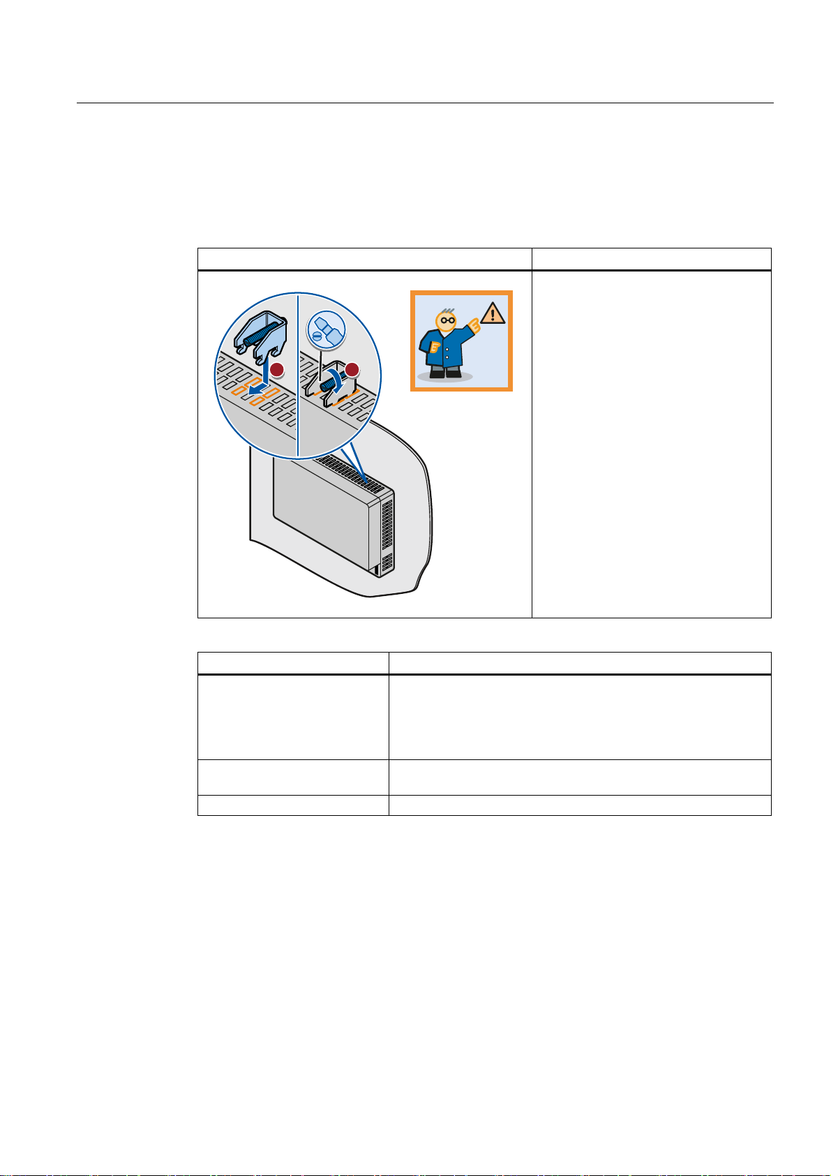
The following graphical highlighting facilitates reading these operating instructions:
Graphical highlighting Description
If the instructions involve several tasks,
the individual tasks are highlighted by a
red number circle.
A light blue highlight indicates
ื 0.2
Nm
.73
components and tools that are required
in the course of a task.
Safety instructions are highlighted by an
orange frame.
KTP600 Basic is sometimes shown in
the illustrations as a representation of all
Basic Panels.
The following text highlighting facilitates reading these operating instructions:
Text highlighting Scope
"Add screen"
"File > Edit" Operational sequences, for example, menu commands, shortcut
<F1> Keyboard operation
• Terms that appear in the user interface, for example, dialog
names, tabs, buttons, menu commands
• Input values, for example, limits, tag values
• Path information
menu commands
Configuration and runtime software have different names as follows:
● "WinCC flexible 2008" or "WinCC (TIA Portal) V11", for example, refers to the
configuration software.
The term "WinCC flexible" or "WinCC" is used in a general context. The full name, for
example, "WinCC flexible 2008", is always used when it is necessary to differentiate
between different versions of the configuration software.
● "WinCC flexible Runtime" or "WinCC Runtime" refers to the runtime software that can run
on HMI devices.
Basic Panels
Operating Instructions, 04/2012, A5E02421799-03
5
Page 6

Preface
Note information highlighted as follows:
Note
A note contains important information on described products and their handling or on a
section of this documentation.
Trademarks
Names labeled with a ® symbol are registered trademarks of the Siemens AG. Other names
used in this documentation may be trademarks, the use of which by third parties for their
own purposes could violate the rights of the owner.
®
● HMI
● SIMATIC
● SIMATIC HMI
● WinCC
®
®
®
Basic Panels
6 Operating Instructions, 04/2012, A5E02421799-03
Page 7

Table of contents
Preface ...................................................................................................................................................... 3
1
Overview.................................................................................................................................................. 11
1.1
1.2
1.3
1.4
1.5
1.6
1.7
1.8
1.9
1.10
1.11
1.12
1.13
2
Safety instructions ................................................................................................................................... 25
2.1
2.2
2.3
Product Overview.........................................................................................................................11
Design of the KP300 Basic mono PN ..........................................................................................12
Design of the KP400 Basic color PN ...........................................................................................13
Design of the KTP400 Basic mono PN........................................................................................15
Design of the KTP400 Basic color PN.........................................................................................16
Design of the KTP600 Basic mono/color PN...............................................................................17
Design of the KTP600 Basic color DP.........................................................................................18
Design of the KTP1000 Basic color PN.......................................................................................19
Design of the KTP1000 Basic color DP.......................................................................................20
Design of the TP1500 Basic color PN .........................................................................................21
Product package ..........................................................................................................................22
Accessories..................................................................................................................................23
Commissioning the HMI device ...................................................................................................24
General safety instructions ..........................................................................................................25
Security information .....................................................................................................................26
Notes about usage.......................................................................................................................26
3
Mounting and connecting......................................................................................................................... 29
3.1
3.1.1
3.1.2
3.1.3
3.1.4
3.1.5
3.1.6
3.2
3.3
3.3.1
3.3.2
3.3.3
3.3.4
3.3.5
3.3.6
Basic Panels
Operating Instructions, 04/2012, A5E02421799-03
Preparations.................................................................................................................................29
Checking the package contents...................................................................................................29
Checking the operating conditions...............................................................................................29
Selecting a mounting position......................................................................................................29
Checking clearances....................................................................................................................31
Making the mounting cut-out........................................................................................................31
Labeling the function keys ...........................................................................................................33
Mounting the HMI device .............................................................................................................34
Connecting the HMI device..........................................................................................................36
Connection sequence ..................................................................................................................36
Connecting the equipotential bonding circuit...............................................................................38
Connecting the power supply.......................................................................................................39
Connecting a programming device ..............................................................................................41
Connecting the configuration PC .................................................................................................42
Connecting the PLC.....................................................................................................................45
7
Page 8

Table of contents
3.4 Switching on and testing the HMI device .................................................................................... 48
3.5 Securing the cables..................................................................................................................... 50
4
Operating the device................................................................................................................................ 51
4.1
4.1.1
4.1.2
4.1.3
4.1.4
4.2
4.2.1
4.2.2
4.3
4.3.1
4.3.2
Configuring the HMI device...................................................................................................................... 67
5
5.1
5.1.1
5.1.2
5.1.3
5.1.4
5.1.5
5.1.6
5.1.7
5.1.8
5.1.9
5.1.10
5.1.11
5.1.12
5.1.13
Operating touch devices ............................................................................................................. 51
Overview ..................................................................................................................................... 51
General functions of the screen keyboard .................................................................................. 53
Entering data on the KTP400 Basic............................................................................................ 54
Entering data on the KTP600 Basic, KTP1000 Basic , TP1500 Basic ....................................... 57
Operating KP300 Basic............................................................................................................... 59
Overview ..................................................................................................................................... 59
Entering data on the KP300 Basic .............................................................................................. 60
Operating KP400 Basic............................................................................................................... 63
Overview ..................................................................................................................................... 63
Entering data on the KP400 Basic .............................................................................................. 66
Configuring devices with graphical Control Panel ...................................................................... 67
Opening the Control Panel.......................................................................................................... 67
Overview ..................................................................................................................................... 68
Changing MPI/DP settings.......................................................................................................... 69
Changing the network configuration ........................................................................................... 70
Time server configuration............................................................................................................ 71
Changing monitor settings .......................................................................................................... 72
Displaying information about the HMI device.............................................................................. 73
Calibrating the touch screen ....................................................................................................... 74
Displaying licensing information for the HMI device ................................................................... 75
Enabling a data channel.............................................................................................................. 76
Changing password settings....................................................................................................... 78
Setting the Screen Saver ............................................................................................................ 79
Setting acoustic signals............................................................................................................... 79
5.2
5.2.1
5.2.2
5.2.3
5.2.4
5.2.5
5.2.6
5.2.7
5.2.8
5.2.9
Commissioning a project.......................................................................................................................... 89
6
6.1
6.2
6.3
Basic Panels
Configuring KP300 Basic ............................................................................................................ 80
Opening the Control Panel.......................................................................................................... 80
Overview ..................................................................................................................................... 81
Displaying information about the HMI device.............................................................................. 83
Changing monitor settings .......................................................................................................... 83
Enabling a data channel.............................................................................................................. 84
Changing the network configuration ........................................................................................... 85
Time server configuration............................................................................................................ 86
Changing password settings....................................................................................................... 87
Setting the Screen Saver ............................................................................................................ 88
Overview ..................................................................................................................................... 89
Operating modes......................................................................................................................... 90
Data transmission options........................................................................................................... 91
8 Operating Instructions, 04/2012, A5E02421799-03
Page 9

Table of contents
6.4 Transfer........................................................................................................................................91
6.4.1 Overview......................................................................................................................................91
6.4.2
6.4.3
6.4.4
Starting manual transfer...............................................................................................................91
Starting automatic transfer...........................................................................................................93
Testing a project ..........................................................................................................................95
6.5
6.5.1
6.5.2
6.5.3
6.5.4
6.6
6.6.1
6.6.2
6.6.3
6.6.4
6.7
6.7.1
6.7.2
6.7.3
6.7.4
6.7.5
6.7.6
6.7.7
6.7.8
Maintenance and care ........................................................................................................................... 115
7
7.1
7.2
Backup and restore......................................................................................................................96
Overview ......................................................................................................................................96
Backup and restore using WinCC flexible ...................................................................................97
Backup and restore using ProSave .............................................................................................99
Backup and restore using WinCC..............................................................................................100
OS update - Basic Panel DP......................................................................................................101
Overview ....................................................................................................................................101
Resetting factory settings...........................................................................................................102
Updating the Operating System using WinCC flexible ..............................................................102
Updating the Operating System using ProSave ........................................................................104
OS update - Basic Panel PN......................................................................................................105
Overview ....................................................................................................................................105
Resetting factory settings...........................................................................................................106
Updating the operating system using WinCC flexible................................................................106
Updating the operating system using ProSave..........................................................................108
Updating the operating system using WinCC............................................................................109
Resetting to factory settings with WinCC flexible ......................................................................110
Resetting to factory settings with ProSave ................................................................................112
Resetting to factory settings with WinCC...................................................................................114
Maintenance and care ...............................................................................................................115
Recycling....................................................................................................................................116
8
Technical specifications......................................................................................................................... 117
8.1
8.2
8.2.1
8.2.2
8.3
8.3.1
8.3.2
8.3.3
8.3.4
8.3.5
8.3.6
8.3.7
8.3.8
8.3.9
Basic Panels
Operating Instructions, 04/2012, A5E02421799-03
Certificates and approvals .........................................................................................................117
Directives and declarations........................................................................................................118
Electromagnetic compatibility ....................................................................................................118
ESD guideline ............................................................................................................................119
Dimension drawings...................................................................................................................122
Dimension drawing of the KP300 Basic mono PN.....................................................................122
Dimension drawing of the KP400 Basic color PN......................................................................123
Dimension drawing of the KTP400 Basic mono PN ..................................................................124
Dimension drawing of the KTP400 Basic color PN....................................................................125
Dimension drawing of the KTP600 Basic color DP....................................................................126
Dimension drawing of the KTP600 Basic mono/color PN .........................................................127
Dimension drawing of the KTP1000 Basic color DP..................................................................128
Dimension drawing of the KTP1000 Basic color PN..................................................................129
Dimension drawing of the TP1500 Basic color PN....................................................................130
9
Page 10

Table of contents
8.4 Specifications ............................................................................................................................ 131
8.4.1 Power supply............................................................................................................................. 131
8.4.2
8.4.3
8.4.4
8.4.5
8.4.5.1
8.4.5.2
8.4.5.3
KP300 Basic and KP400 Basic................................................................................................. 131
KTP400 Basic and KTP600 Basic ............................................................................................ 133
KTP1000 Basic and TP1500 Basic........................................................................................... 135
Ambient conditions.................................................................................................................... 137
Transport and storage conditions ............................................................................................. 137
Conditions of use ...................................................................................................................... 138
Information on insulation tests, protection class and degree of protection............................... 140
8.5
8.5.1
8.5.2
8.5.3
8.6
A
Technical Support.................................................................................................................................. 147
A.1
A.2
B
Abbreviations......................................................................................................................................... 149
Glossary ................................................................................................................................................ 151
Index...................................................................................................................................................... 157
Interface description.................................................................................................................. 141
Power supply............................................................................................................................. 141
PROFIBUS (Sub-D RS422/485) ............................................................................................... 141
PROFINET (Ethernet)............................................................................................................... 142
Functional scope with WinCC flexible and WinCC ................................................................... 143
Service and support .................................................................................................................. 147
System events........................................................................................................................... 148
Basic Panels
10 Operating Instructions, 04/2012, A5E02421799-03
Page 11

Overview
1.1 Product Overview
Concentrating on the essentials - the new Basic Panels
Today, visualization is part of the standard repertoire for most machines. The cost factor
plays a crucial role in this case, especially for small machines and simple applications. HMI
devices with basic functions are often fully sufficient for simple applications.
This is exactly the demand that we intend to meet – with our new SIMATIC HMI Basic
Panels. By concentrating on the essentials, the Basic Panels offer exactly those basic
features that are demanded – at the right price. A perfect cost-to-performance ratio.
Like all devices in our product catalog, the new Basic Panels offer proven SIMATIC quality
and – regardless of their display dimensions – many software functions as standard: for
example, an alarm system, recipe management, trend functionality and language switching.
Users therefore profit from the advantages of visualization, such as improved process
quality, even with simple applications.
1
Basic Panels
Operating Instructions, 04/2012, A5E02421799-03
11
Page 12

Overview
1.2 Design of the KP300 Basic mono PN
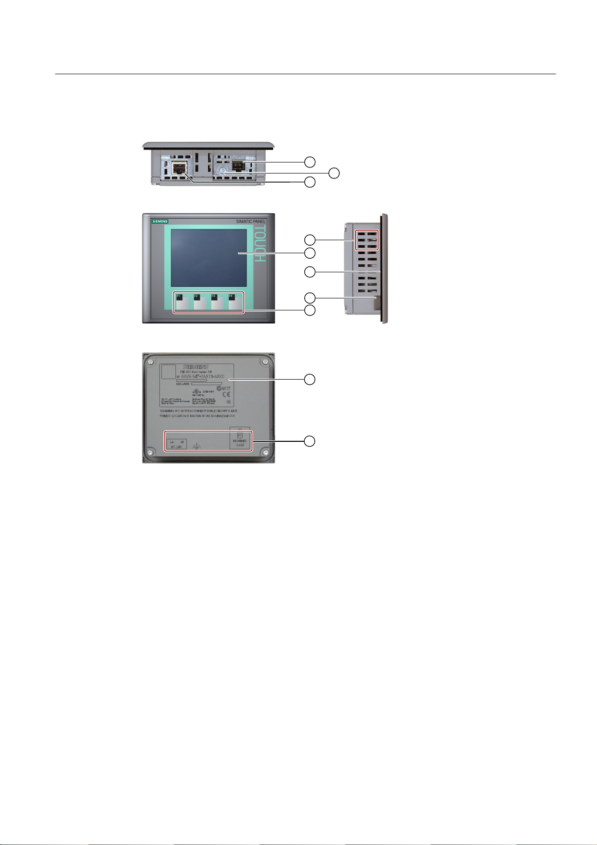
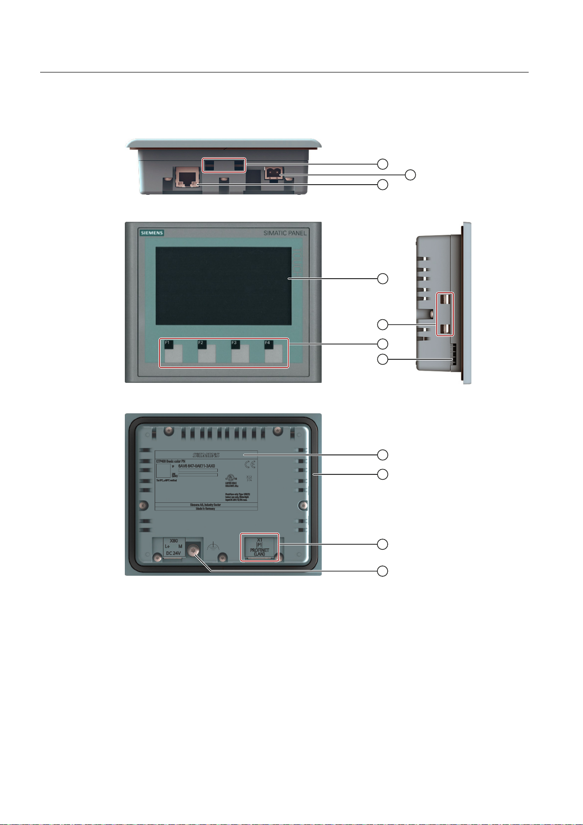
1.2 Design of the KP300 Basic mono PN
① Power supply connector ⑥ Function keys
② PROFINET interface ⑦ Rating plate
③ Display ⑧ Mounting seal
④ Control keys ⑨ Interface name
⑤ Cutouts for a mounting clamp ⑩ Functional earth connection
Basic Panels
12 Operating Instructions, 04/2012, A5E02421799-03
Page 13

Overview
1.3 Design of the KP400 Basic color PN
1.3 Design of the KP400 Basic color PN
① Cutouts for mounting clamps ⑤ Function keys
② Power supply connector ⑥ Control keys
③ PROFINET interface ⑦ Data input keys
④ Display
Basic Panels
Operating Instructions, 04/2012, A5E02421799-03
13
Page 14

Overview
1.3 Design of the KP400 Basic color PN
① Rating plate ④ Functional earth connection
② Mounting seal ⑤ Guides for labeling strips
③ Interface name
Basic Panels
14 Operating Instructions, 04/2012, A5E02421799-03
Page 15
Overview
1.4 Design of the KTP400 Basic mono PN
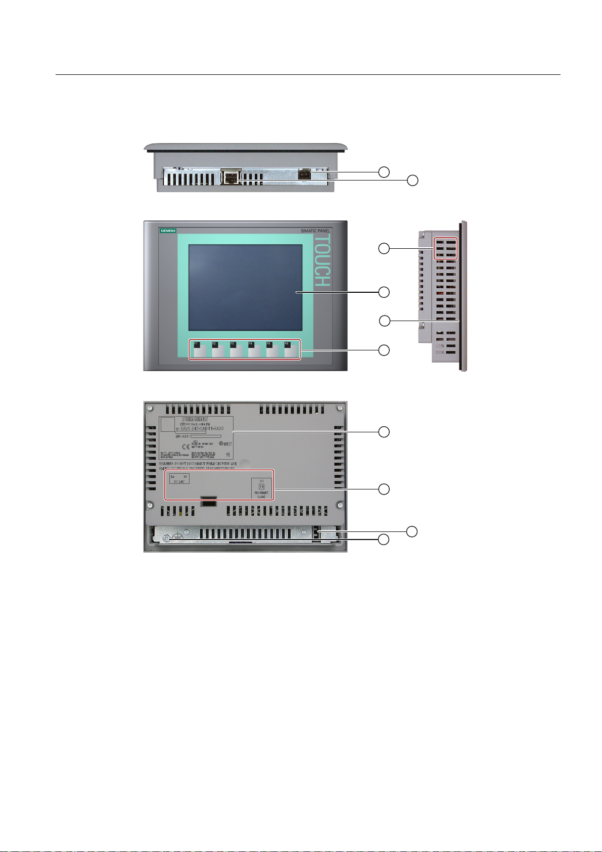
1.4 Design of the KTP400 Basic mono PN
① Power supply connector ⑥ Mounting seal
② Functional earth connection ⑦ Guide for a labeling strip
③ PROFINET interface ⑧ Function keys
④ Cutouts for a mounting clamp ⑨ Rating plate
⑤ Display/touch screen ⑩ Interface name
Basic Panels
Operating Instructions, 04/2012, A5E02421799-03
15
Page 16
Overview
1.5 Design of the KTP400 Basic color PN
1.5 Design of the KTP400 Basic color PN
① Cutouts for mounting clamps ⑥ Guide for a labeling strip
② Power supply connector ⑦ Rating plate
③ PROFINET interface ⑧ Mounting seal
④ Display/touch screen ⑨ Interface name
⑤ Function keys ⑩ Functional earth connection
Basic Panels
16 Operating Instructions, 04/2012, A5E02421799-03
Page 17
Overview
1.6 Design of the KTP600 Basic mono/color PN
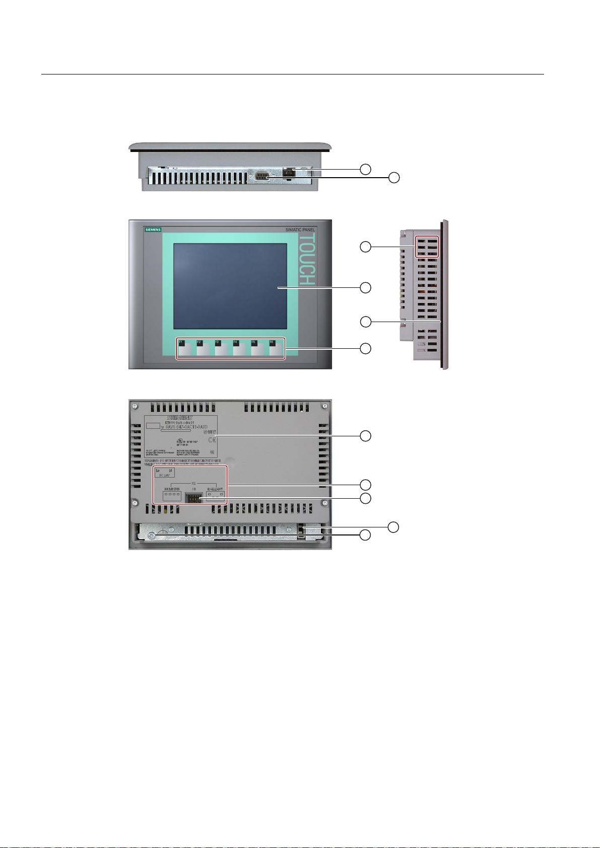
1.6 Design of the KTP600 Basic mono/color PN
① Power supply connector ⑥ Function keys
② PROFINET interface ⑦ Rating plate
③ Cutouts for a mounting clamp ⑧ Interface name
④ Display/touch screen ⑨ Guide for a labeling strip
⑤ Mounting seal ⑩ Functional earth connection
Basic Panels
Operating Instructions, 04/2012, A5E02421799-03
17
Page 18
Overview
1.7 Design of the KTP600 Basic color DP
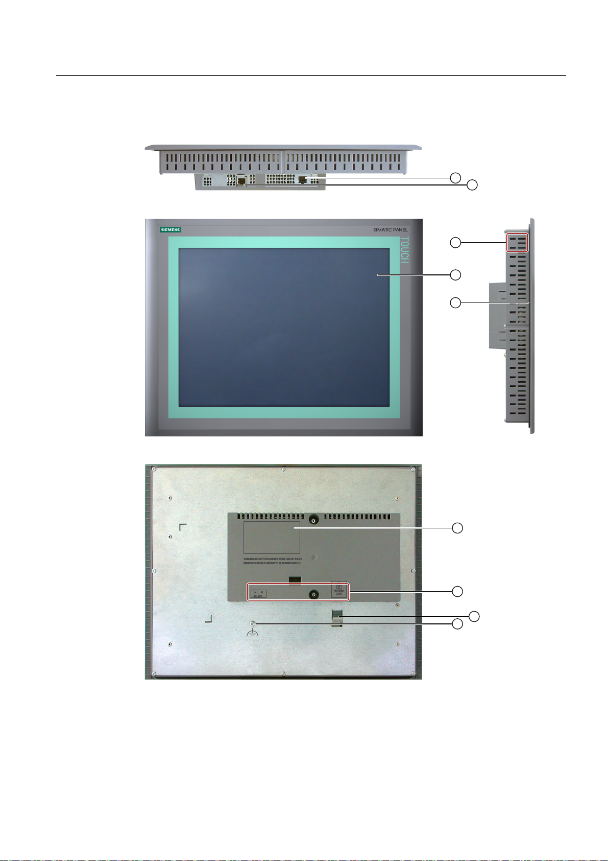
1.7 Design of the KTP600 Basic color DP
① Power supply connector ⑦ Rating plate
② RS-422/RS-485 interface ⑧ Interface name
③ Cutouts for a mounting clamp ⑨ DIP switch
④ Display/touch screen ⑩ Guide for a labeling strip
⑤ Mounting seal ⑪ Functional earth connection
⑥ Function keys
Basic Panels
18 Operating Instructions, 04/2012, A5E02421799-03
Page 19

Overview
1.8 Design of the KTP1000 Basic color PN
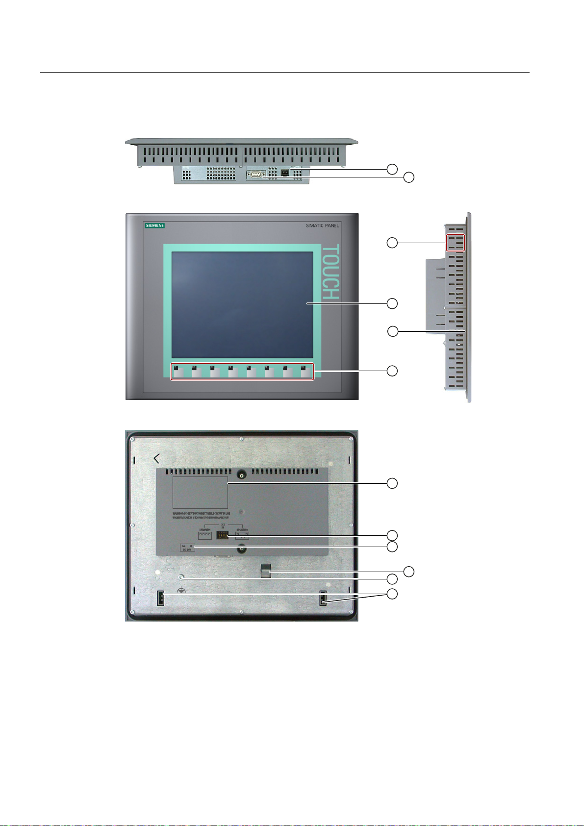
1.8 Design of the KTP1000 Basic color PN
① Power supply connector ⑦ Rating plate
② PROFINET interface ⑧ Interface name
③ Cutouts for a mounting clamp ⑨ Fixing element
④ Display/touch screen ⑩ Functional earth connection
⑤ Mounting seal ⑪ Guide for labeling strips
⑥ Function keys
Basic Panels
Operating Instructions, 04/2012, A5E02421799-03
19
Page 20
Overview
1.9 Design of the KTP1000 Basic color DP
1.9 Design of the KTP1000 Basic color DP
① Power supply connector ⑦ Rating plate
② RS-422/RS-485 interface ⑧ DIP switch
③ Cutouts for a mounting clamp ⑨ Interface name
④ Display/touch screen ⑩ Fixing element
⑤ Mounting seal ⑪ Functional earth connection
⑥ Function keys ⑫ Guides for labeling strips
Basic Panels
20 Operating Instructions, 04/2012, A5E02421799-03
Page 21
Overview
1.10 Design of the TP1500 Basic color PN
1.10 Design of the TP1500 Basic color PN
① Power supply connector ⑥ Rating plate
② PROFINET interface ⑦ Interface name
③ Cutouts for a mounting clamp ⑧ Fixing element
④ Display/touch screen ⑨ Functional earth connection
⑤ Mounting seal
Basic Panels
Operating Instructions, 04/2012, A5E02421799-03
21
Page 22
Overview
1.11 Product package
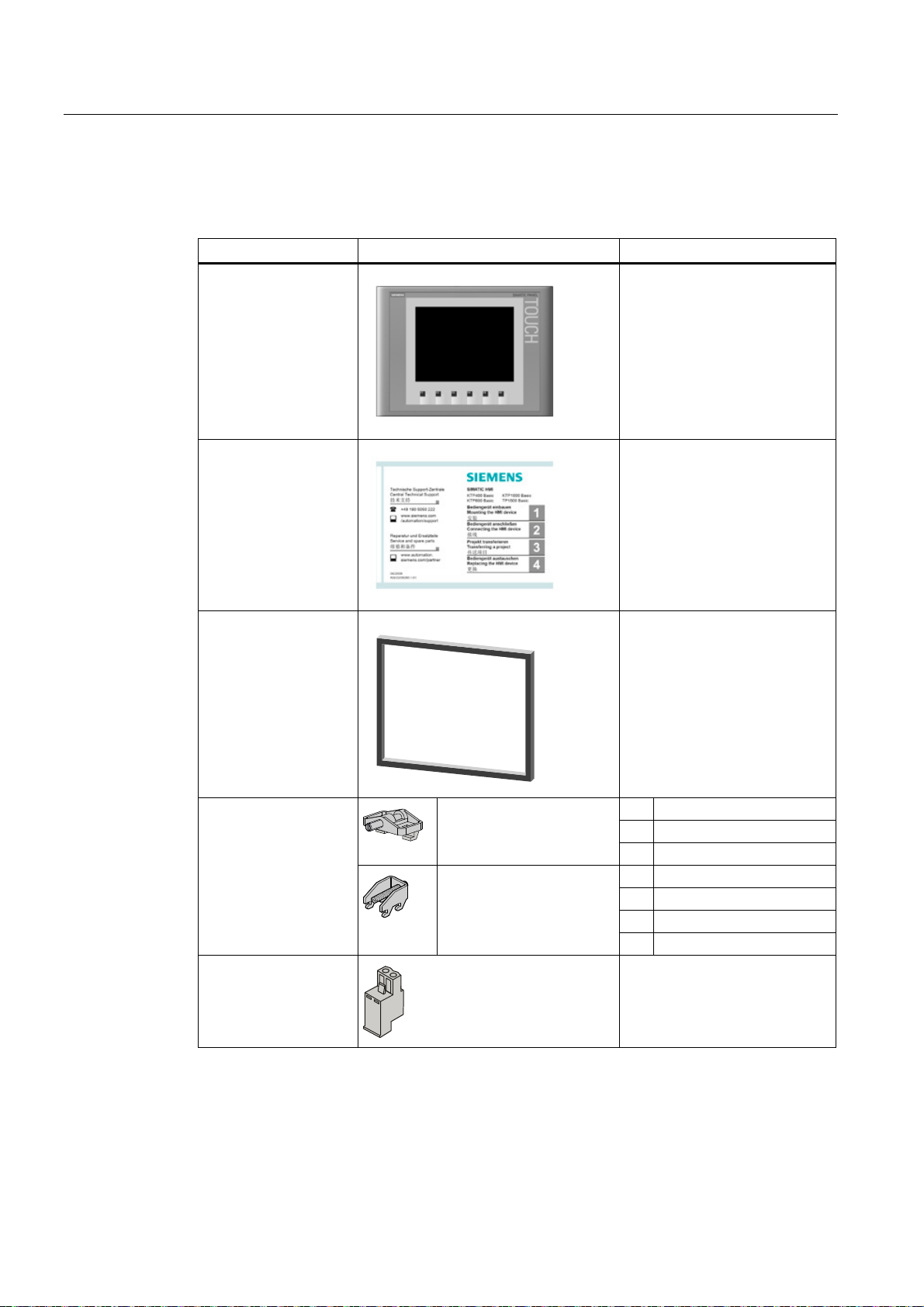
1.11 Product package
The following components are included in the product package of the HMI device.
Name Figure Quantity
HMI device
1
Quick Installation Guide
Mounting seal
Mounting clamps with
grub screw
Power supply terminal
Plastic mounting clamps
Aluminum mounting
clamps
1
1
Included with KTP 600 Basic and
already installed with all other
HMI devices.
4 KP300 Basic
7 KP400 Basic
5 KTP400 Basic color PN
5 KTP400 Basic mono PN
6 KTP600 Basic
12 KTP1000 Basic
14 TP1500 Basic
1
Basic Panels
22 Operating Instructions, 04/2012, A5E02421799-03
Page 23

Overview
1.12 Accessories
1.12 Accessories
Accessories are not included in the product package of the HMI device, but can ordered on
the Internet under Industry Mall (http://mall.automation.siemens.com
This section contains the number of accessories available at the time of publication of the
operating instructions.
).
Converters, adapters and connectors
Name Purpose Order no.
RS 422 to RS 232
converter
PC/PPI cable Converts RS 422/RS 485 signals to RS 232
90 degree elbow
adapter
USB/PPI cable Converts RS 422/RS 485 signals to USB
PROFIBUS connector Recommended PROFIBUS connector with
PROFINET RJ45
connector "IE FC RJ45
Plug 2x2"
1
If the connection is lost during the operating system update, set a lower bit rate. If you use a higher
bit rate, you must use the PC/PPI cable release 3 or higher. The release code is printed on the
cable ("E version 3," for example, corresponds to release 3).
Connection of third-party controllers to Basic
Panels DP
signals. Is required for updating the operating
system with reset to factory settings
be used for the transfer.
For RS422/RS485 interface, cable outlet to rear 6AV6671-8XD00-0AX0
signals. Is required for updating the operating
system with reset to factory settings. Can also
be used for the transfer.
straight cable outlet
Required for connection of Basic Panels PN to
PROFINET
1
. Can also
6AV6671-8XE00-0AX0
6ES7 901-3CB30-0XA0
6ES7 901-3DB30-0XA0
6GK1500-0FC10
6GK1901-1BB10-2AA0
Clamping frame
Basic Panels
Operating Instructions, 04/2012, A5E02421799-03
Name Purpose Order no.
Clamping frame
for 10"/12" Touch
For reinforcement of the mounting cutout for
KTP1000 Basic when material is not thick
enough
6AV6 671-8XS00-0AX0
23
 Loading...