

Page 1
Important Notes, Contents
SIMATIC
FM 456-2 Application Function
Module
Installation, Hardware, and
Startup
Manual
This manual has the order number:
6ES7 456-2AA00-8BA0
User Information
Product Overview
Installation and Startup
Replacing Modules
Reference Information
FM 456-2 Functions and
Technical Data
Ordering Information
Appendices
Bibliography
1
2
3
4
5
A
05/99
Edition 01
Rules for Handling
Electrostatically Sensitive
Devices (ESD)
Index
B
Page 2
Chapter
Safety Guidelines
This manual contains notices which you should observe to ensure your own personal safety, as well as to
protect the product and connected equipment. These notices are highlighted in the manual by a warning
triangle and are marked as follows according to the level of danger:
Danger
!
indicates that death, severe personal injury or substantial property damage will result if proper precautions are not taken.
Warning
!
indicates that death, severe personal injury or substantial property damage can result if proper precautions are not taken.
Caution
!
indicates that minor personal injury or property damage can result if proper precautions are not taken.
Note
draws your attention to particularly important information on the product, handling the product, or to a
particular part of the documentation.
Qualified Personnel
Only qualified personnel should be allowed to install and work on this equipment. Qualified persons are
defined as persons who are authorized to commission, to ground, and to tag circuits, equipment, and systems in accordance with established safety practices and standards.
Correct Usage
Note the following:
Warning
!
Trademarks
This device and its components may only be used for the applications described in the catalog or the
technical descriptions, and only in connection with devices or components from other manufacturers
which have been approved or recommended by Siemens.
This product can only function correctly and safely if it is transported, stored, set up, and installed correctly, and operated and maintained as recommended.
SIMA TICR, SIMA TIC HMIR and SIMA TIC NETR are registered trademarks of SIEMENS AG.
Some of other designations used in these documents are also registered trademarks; the owner’s rights
may be violated if they are used by third parties for their own purposes.
The reproduction, transmission or use of this document or its contents is not
permitted without express written authority. Offenders will be liable for
damages. All rights, including rights created by patent grant or registration of
a utility model or design, are reserved.
Siemens AG
Bereich Automatisierungs- und Antriebstechnik
Geschaeftsgebiet Industrie-Automatisierungssysteme
Postfach 4848, D- 90327 Nuernberg
Index-2
Siemens Aktiengesellschaft
FM 456-2 Application Function Module Installation, Hardware, and Startup
Disclaimer of LiabilityCopyright Siemens AG 1998 All rights reserved
We have checked the contents of this manual for agreement with the hardware and software described. Since deviations cannot be precluded entirely,
we cannot guarantee full agreement. However, the data in this manual are
reviewed regularly and any necessary corrections included in subsequent
editions. Suggestions for improvement are welcomed.
E Siemens AG 1998
T echnical data subject to change.
6ES7456-2AA00-8BA0
05/99
Page 3
Important Notes
Purpose of the Manual
The information in this manual will enable you to:
Design a configuration from the M7-400 range and build it into an S7/M7-400
programmable logic control system.
Look up operating instructions, functional descriptions and technical data for
specific modules.
Audience
The manual is intended for the following readers:
Users who plan and design the scope of a programmable logic controller.
Users who require detailed technical data.
Service and maintenance engineers who have to install and maintain
programmable logic controllers.
Scope of This Manual
The manual applies to the following M7-400 modules:
Product Order Number From Release
FM 456-2 6ES7 456-2AA00-0AB0 1
FM 456-2 with MS-DOS 6ES7 456-2AA00-0AB1 1
This manual contains descriptions of all the modules that are valid at the time of
issue of this manual. We reserve the right in the case of new modules and new
releases of modules to provide product information sheets containing up-to-date
information about those modules.
Note
The structure of an S7-/M7-400 system is described in
the content and requirements of
application function modules into a S7/M7-400 system.
manual /1/
manual /1/
is a prerequisite for integrating M7-400
. Familiarity with
FM 456-2 Application Function Module Installation, Hardware, and Startup
C79000-G7076-C458-01
iii
Page 4
Important Notes
What is New in the FM 456-2?
In comparison to the FM 456-4, the preceding product, the FM 456, shows the
following alterations:
Feature FM 456-4 (old) FM 456-2 (new)
Processor 80486DX, 75 MHz Pentium, 120 MHz
SRAM, buffered 64 Kbytes 256 Kbytes
Reading and
writing of records
Main memory suitable for expansion with 16 MB RAM 16 MB RAM installed
Operating system M7-SYS up to V2.0 inclusive
only SD0 and SD1 system records all system and user records
M7-SYS RT up to V4.0 inclusive
Width 25 mm (1”) 50 mm (2”)
OSD
(Flash EPROM)
yes no
M7-SYS RT from V5.0
Approvals
CE Marking
The following approvals have been granted for the S7-400/M7-400:
UL recognition mark
Underwriters Laboratories (UL) to
standard UL 508, report E 85972
CSA certification mark
Canadian Standard Association (CSA) to
standard C 22.2 No. 142, report LR 63533
FM approval
according to Factory Mutual Approval Standard
Class Number 3611, Class I, Division 2, Group A, B, C, D.
For further information, please refer to Chapter 1 of the
reference manual /1/
.
This product complies with the requirements of the EU directives which are listed
in Chapter 1 of
reference manual /1/
.
iv
FM 456-2 Application Function Module Installation, Hardware, and Startup
C79000-G7076-C458-01
Page 5
Area of Use
The following areas of use apply to the S7-400/M7-400 systems in accordance
with this CE mark:
Area of use Requirements for
Industry EN 50081-2: 1993 EN 50082-2: 1995
Observe the Installation Guidelines
Important Notes
Interference emission Interference resistance
The installation guidelines and safety notes given in the manual
Programmable Controllers
the S7-400/M7-400 systems.
How to Use This Manual
This manual provides the information you need to install M7-400 application
function modules in an S7/M7-400 controller.
Product Overview
Chapter1 provides an overview of the M7-400 function modules.
Configuring, Addressing
You will find the information you need for this in
Installation and Startup
Chapter 2 shows you how to install the M7-400 application function modules and
prepare them for startup.
Replacing Modules
Chapter 3 describes how to replace M7-400 application function modules.
Functions, Technical Data
S7-400, M7-400
must be observed when commissioning and operating
manual /1/
.
Chapter 4 provides a detailed description of the FM 456-2 application function
module. You will also find the technical data in this section.
Ordering Information
Chapter 5 contains ordering information for M7-400 components as well as
I/O modules and accessories not described in this manual.
Bibliography
Appendix A contains references to further literature that may be helpful in certain
cases.
Index
At the end of the manual is a comprehensive index to give you quick access to the
information you require.
FM 456-2 Application Function Module Installation, Hardware, and Startup
C79000-G7076-C458-01
v
Page 6

Important Notes
Feedback on documentation
We need your help to enable us to provide you and future users with optimum
documentation. Should you have any remarks on this
remarks form at the end of the manual and return it to the address shown on the
form. Please also indicate your personal opinion of the manual.
SIMATIC Customer Support Hotline
Available 24 hours a day, worldwide:
Johnson City
Nuremberg
manual,
please fill out the
Nuremberg
SIMA TIC BASIC Hotline
Local time: Mon. through Fri.
7.00 a.m. to 5.00 p.m.
Phone: +49 (911) 895-7000
Fax: +49 (91 1) 895-7002
E-mail: simatic.support@
nbgm.siemens.de
GMT +01.00
SIMA TIC Premium Hotline
(subject to charge, with SIMATIC
Card only)
Time: Mon. through Fri. 0.00
a.m. to 12.00 p.m.
Phone: +49 (911) 895-7777
Fax: +49 (911) 895-7001
GMT +01.00
Simatic Basic Hotline
Johnson City
SIMA TIC BASIC Hotline
Local time: Mon. through Fri.
8.00 a.m. to 5.00 p.m.
Phone: +1 423 461-2522
Fax: +1 423 461-2231
E-mail: simatic.hotline@
sea.siemens.com
GMT –5.00
Singapore
Singapore
SIMA TIC BASIC Hotline
Local time: Mon. through Fri.
8.30 a.m. to 5.30 p.m.
Phone: +65 740-7000
Fax: +65 740-7001
E-mail: simatic@
singnet.com.sg
GMT +8:00
vi
FM 456-2 Application Function Module Installation, Hardware, and Startup
C79000-G7076-C458-01
Page 7

SIMATIC Training Center
We offer a number of courses to help you become familiar with the SIMATIC S7
programmable logic controller. Please contact your regional training center or the
central training center in Nuremberg, Germany, for details.
Phone: +49 (911) 895-3154.
SIMATIC Customer Support Online Services
SIMATIC Customer Support provides you with comprehensive additional
information in SIMATIC products by means of its online services:
You can obtain general current information on the Internet at
http://www.ad.siemens.de/simatic
Current product information leaflets and downloads which you may find useful
for your product:
– On the Internet at http://www.ad.siemens.de/support/html_00/
To access the mailbox, use a modem with up to V.34 (28.8 kbps) capability
whose parameters you should set as follows: 8, N, 1, ANSI, or dial in using
ISDN (x.75, 64 kbps).
Important Notes
FM 456-2 Application Function Module Installation, Hardware, and Startup
C79000-G7076-C458-01
vii
Page 8

Important Notes
viii
FM 456-2 Application Function Module Installation, Hardware, and Startup
C79000-G7076-C458-01
Page 9

Contents
1 Product Overview 1-1. . . . . . . . . . . . . . . . . . . . . . . . . . . . . . . . . . . . . . . . . . . . . . . . . . . . . .
1.1 Overview 1-2. . . . . . . . . . . . . . . . . . . . . . . . . . . . . . . . . . . . . . . . . . . . . . . . . . . . . . .
1.2 Applications 1-5. . . . . . . . . . . . . . . . . . . . . . . . . . . . . . . . . . . . . . . . . . . . . . . . . . . .
1.3 Inserting the FM 456-2 in the S7-400 Racks 1-6. . . . . . . . . . . . . . . . . . . . . . . .
1.4 Module Overview 1-7. . . . . . . . . . . . . . . . . . . . . . . . . . . . . . . . . . . . . . . . . . . . . . . .
2 Installation and Startup 2-1. . . . . . . . . . . . . . . . . . . . . . . . . . . . . . . . . . . . . . . . . . . . . . . . .
2.1 Installation Checklist and Switch-on Test 2-2. . . . . . . . . . . . . . . . . . . . . . . . . . .
2.2 Module Accessories 2-3. . . . . . . . . . . . . . . . . . . . . . . . . . . . . . . . . . . . . . . . . . . . .
2.3 Installing Interface Submodules 2-4. . . . . . . . . . . . . . . . . . . . . . . . . . . . . . . . . . .
2.4 Installing a Short AT Card 2-6. . . . . . . . . . . . . . . . . . . . . . . . . . . . . . . . . . . . . . . .
2.5 Fitting Expansion Modules to an FM 456-2 2-8. . . . . . . . . . . . . . . . . . . . . . . . . .
2.6 Installing a Module Assembly in the Module Rack 2-14. . . . . . . . . . . . . . . . . . . .
2.7 Inserting/Removing a Memory Card 2-18. . . . . . . . . . . . . . . . . . . . . . . . . . . . . . . .
2.8 Connecting a Module Assembly 2-19. . . . . . . . . . . . . . . . . . . . . . . . . . . . . . . . . . .
2.9 Preparing for Operation 2-20. . . . . . . . . . . . . . . . . . . . . . . . . . . . . . . . . . . . . . . . . .
2.10 Connecting the Operator Panels and Peripherals 2-21. . . . . . . . . . . . . . . . . . . .
2.11 Connecting a Programming Device or PC to the COM Interface 2-23. . . . . . .
2.12 Switching On the FM 456-2 for the First Time 2-26. . . . . . . . . . . . . . . . . . . . . . .
3 Replacing Modules 3-1. . . . . . . . . . . . . . . . . . . . . . . . . . . . . . . . . . . . . . . . . . . . . . . . . . . . .
3.1 Replacing the Interface Submodule 3-2. . . . . . . . . . . . . . . . . . . . . . . . . . . . . . . .
3.2 Replacing an Application Function Module or Expansion Module in a
Module Assembly 3-4. . . . . . . . . . . . . . . . . . . . . . . . . . . . . . . . . . . . . . . . . . . . . . .
3.3 Replacing the Short AT Module 3-9. . . . . . . . . . . . . . . . . . . . . . . . . . . . . . . . . . .
FM 456-2 Application Function Module Installation, Hardware, and Startup
C79000-G7076-C458-01
ix
Page 10

Contents
4 FM 456-2 Functions and Technical Data 4-1. . . . . . . . . . . . . . . . . . . . . . . . . . . . . . . . . .
4.1 Performance Features 4-2. . . . . . . . . . . . . . . . . . . . . . . . . . . . . . . . . . . . . . . . . . .
4.2 Overview of Hardware Elements 4-2. . . . . . . . . . . . . . . . . . . . . . . . . . . . . . . . . .
4.3 Mode Selector 4-4. . . . . . . . . . . . . . . . . . . . . . . . . . . . . . . . . . . . . . . . . . . . . . . . . .
4.4 Status and Fault Indicators 4-6. . . . . . . . . . . . . . . . . . . . . . . . . . . . . . . . . . . . . . .
4.5 Memory Card 4-7. . . . . . . . . . . . . . . . . . . . . . . . . . . . . . . . . . . . . . . . . . . . . . . . . . .
4.6 Expansion Socket 4-8. . . . . . . . . . . . . . . . . . . . . . . . . . . . . . . . . . . . . . . . . . . . . . .
4.7 Slots for Interface Submodules 4-9. . . . . . . . . . . . . . . . . . . . . . . . . . . . . . . . . . . .
4.8 Watchdog 4-1 1. . . . . . . . . . . . . . . . . . . . . . . . . . . . . . . . . . . . . . . . . . . . . . . . . . . . . .
4.9 Buffering 4-1 1. . . . . . . . . . . . . . . . . . . . . . . . . . . . . . . . . . . . . . . . . . . . . . . . . . . . . . .
4.10 BIOS Setup 4-12. . . . . . . . . . . . . . . . . . . . . . . . . . . . . . . . . . . . . . . . . . . . . . . . . . . .
4.11 Address and Interrupt Assignments 4-13. . . . . . . . . . . . . . . . . . . . . . . . . . . . . . . .
4.12 Technical Data 4-16. . . . . . . . . . . . . . . . . . . . . . . . . . . . . . . . . . . . . . . . . . . . . . . . . .
5 Ordering Information 5-1. . . . . . . . . . . . . . . . . . . . . . . . . . . . . . . . . . . . . . . . . . . . . . . . . . .
A Bibliography A-1. . . . . . . . . . . . . . . . . . . . . . . . . . . . . . . . . . . . . . . . . . . . . . . . . . . . . . . . . . .
B Rules for Handling Electrostatically Sensitive Devices (ESD) B-1. . . . . . . . . . . . . .
B.1 What Does ESD Mean? B-2. . . . . . . . . . . . . . . . . . . . . . . . . . . . . . . . . . . . . . . . . .
B.2 Electrostatic Charging of Persons B-3. . . . . . . . . . . . . . . . . . . . . . . . . . . . . . . . .
B.3 Basic Precautions Against Electrostatic Discharge B-4. . . . . . . . . . . . . . . . . . .
Index Index-1. . . . . . . . . . . . . . . . . . . . . . . . . . . . . . . . . . . . . . . . . . . . . . . . . . . . . . . . . . . . . . . .
x
FM 456-2 Application Function Module Installation, Hardware, and Startup
C79000-G7076-C458-01
Page 11
Product Overview
In this Chapter
Section Subject Page
1.1 Overview 1-2
1.2 Applications 1-5
1.3 Inserting the FM 456-2 in the S7-400 Racks 1-6
1.4 Module Overview 1-7
1
FM 456-2 Application Function Module Installation, Hardware, and Startup
C79000-G7076-C458-01
1-1
Page 12

Product Overview
1.1 Overview
Introduction
In this section, you will learn what the FM 456-2 application function module is and
what it has to offer.
What Is an FM 456-2?
The FM 456-2 is an application function module from the M7-400 family of
automation computers that is used in the S7/M7-400 programmable logic
controller.
The FM 456-2 application function module is an automation computer with PC-HW
architecture for inserting in your S7/M7-400 programmable logic controller rack.
The FM 456-2 is a freely programmable module (application function module) that
can be expanded or combined to form large configurations:
Programmable module with Pentium, 120 MHz; a memory card and up to two
interface modules can be plugged in at the front.
EXM 478 expansion module, each for fitting 3 interface submodules such as
IF 962-VGA, IF 962-COM, IF 962-LPT.
MSM 478 mass storage module with diskette drive, hard disk and “LPT1”
parallel interface.
ATM 478 AT adapter module for installing a short AT module.
Position of an FM 456-2 in the S7 System
Within an S7/M7-400 system an FM 456-2 can be expanded with monitor,
keyboard and mass memory. Integration into the system is performed by the M7
system software.
You can use an FM 456-2 to provide flexibility in meeting specific requirements,
such as application technology tasks (controlling, positioning, metering, ...),
communications, data storage, etc. This considerably reduces the load on the
S7/M7-400 CPU.
1-2
FM 456-2 Application Function Module Installation, Hardware, and Startup
C79000-G7076-C458-01
Page 13
Configuration of an S7-400 with FM 456-2
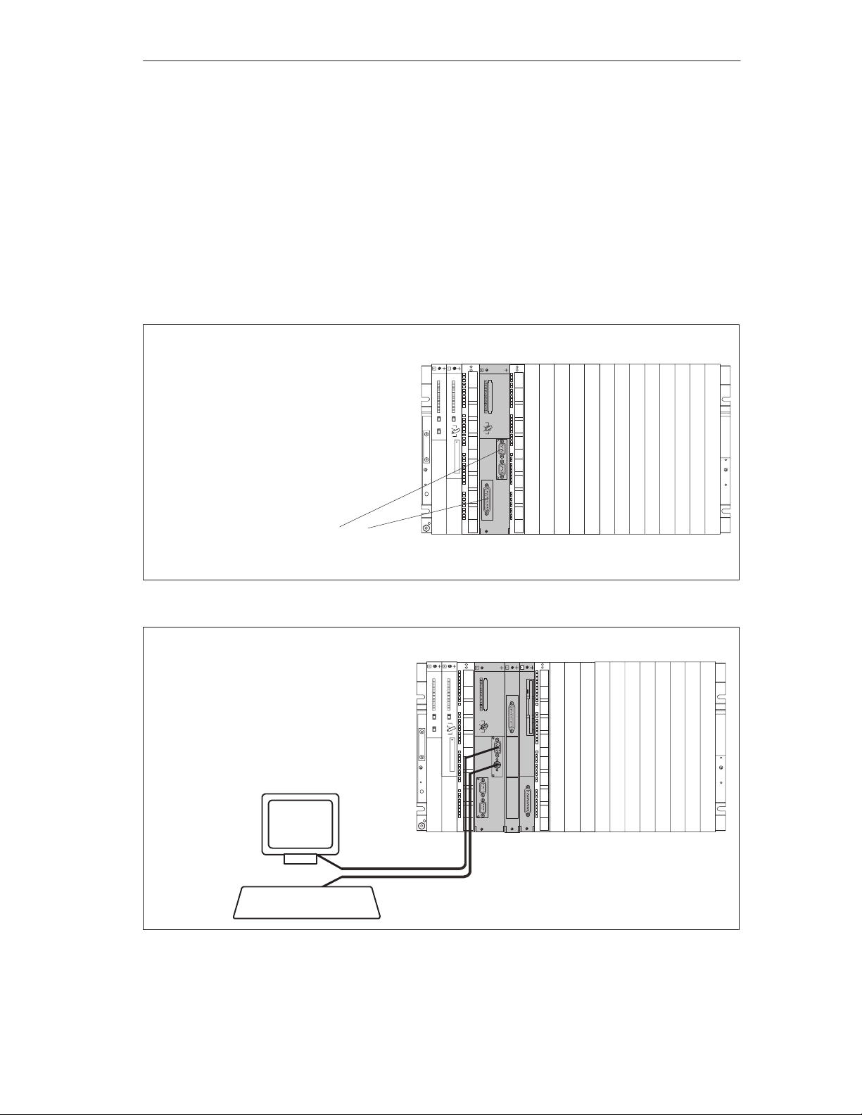
An FM 456-2 with or without expansion modules can be installed in addition to the
S7-400 components. Figures 1-1 and 1-2 illustrate sample configurations:
S FM 456-2 fitted with IF 962-COM and IF 961-CT1 interface submodules,
without expansion modules as application function module in the S7-400
system
S FM 456-2 fitted with IF 962-COM and IF 962-VGA interface submodules, an
EXM 478 expansion module fitted with IF 961-DIO interface submodule and an
MSM 478 mass storage module as automation computer in the S7-400 system
Product Overview
Power supply module (PS)
Central processing unit (CPU)
Signal modules (SM)
Application function module (FM 456-2)
Two optional interface submodules
e. g. IF 962-COM or IF 961-CT1
Figure 1-1 FM 456-2 as Application Function Module in the S7-400 System
Power supply module (PS)
Central processing unit (CPU )
Signal modules (SM)
Application function module (FM 456-2)
(with IF 962-VGA, IF 962-COM)
Expansion module (EXM 478)
(with e. g. IF 961-DIO)
Mass storage module (MSM 478)
VGA monitor
Keyboard
Figure 1-2 FM 456-2 as Automation Computer in the S7-400 System
FM 456-2 Application Function Module Installation, Hardware, and Startup
C79000-G7076-C458-01
1-3
Page 14
Product Overview
M7-400 Components
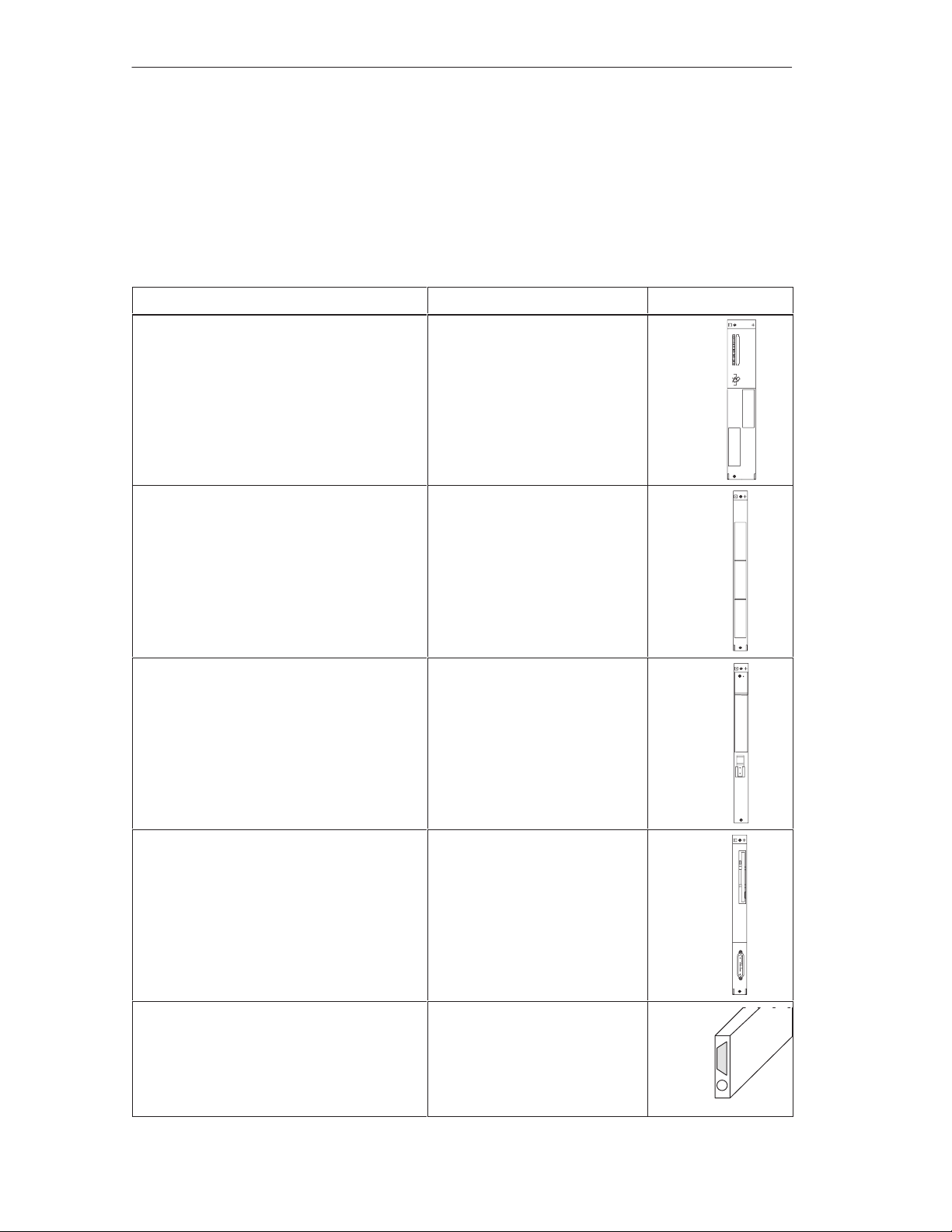
An M7-400 can be equipped or expanded in various ways. The following tables
provide an overview of the components in the M7-400 family of automation
computers.
Table 1-1 Components in the M7-400 Automation Computer Family
Components Function Illustration
Application function module
FM 456-2
Expansion module
EXM 478
AT adapter module
ATM 478
... basic module with PC-HW
architecture.
... provides space for up to 2
interface submodules.
... provides space for 3
interface submodules for
connecting to, for example,
process I/O, VGA monitor,
PG/PC keyboard, printer etc.
... provides space for a short
AT module.
Mass memory module
MSM 478
Interface submodules
Process modules (IF 961)
System modules (IF 962)
Communications modules (IF 964
Profibus-DP and CP 1401 TCP/IP)
1-4
... provides storage for
programs and data on a hard
disk and 3.5 diskette.
... contains an “LPT1” parallel
interface, for example to
connect a printer.
... make the connection from
the process or peripherals to
the FM 456-2.
FM 456-2 Application Function Module Installation, Hardware, and Startup
C79000-G7076-C458-01
Page 15

1.2 Applications
Tasks of an FM 456-2
An FM 456-2 is used as a programmable module in an S7-400 programmable logic
controller in conjunction with an S7/M7-400 CPU. The following are a few typical
tasks or functions for an FM 456-2:
Technological functions (controlling, positioning, counting)
Process data acquisition
Mass storage functions
Data exchange with the S7/M7 CPU
Data exchange with PG/PC
Control of local peripherals
Event-driven program processing
Product Overview
Communications
Areas of Application of an FM 456-2
The FM 456-2 can be used in any application where special technical
requirements, high-speed control or special tasks such as communications, data
storage etc. are to be implemented.
Plastics technology
Process systems
Textile industry
Machine tools
Packaging systems
...
User-Defined Functionality
The functionality of an FM 456-2 is defined by the user. This is achieved through
the programming capability of the module. Powerful M-7 system software and
STEP 7 development and generation software that is easy for the engineer to use
are available for the implementation of the user’s application.
System software
The FM 456-2 can be used with the M7-SYS RT system from release V5.0.
FM 456-2 Application Function Module Installation, Hardware, and Startup
C79000-G7076-C458-01
1-5
Page 16
Product Overview
1.3 Inserting the FM 456-2 in the S7-400 Racks
Inserting in S7-400 Racks
The FM 456-2 application function module can be inserted in different racks of the
S7/M7-400 system.
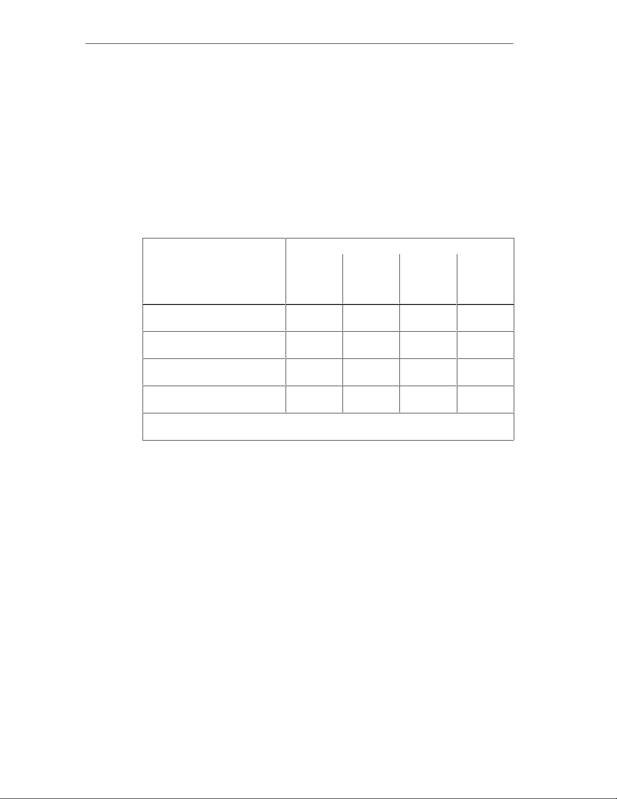
Table 4-4 shows which modules can be inserted in the different racks.
Table 1-2 Insertion Options for M7-400 Modules
Modules Racks
UR1, UR2
as
central unit
Application function module
(FM 456-2)
Expansion module
(EXM 478)
A T adapter module
(ATM 478)
Mass storage module
(MSM 478)
1) Not with 460-1 / 461-1 local link
*) Can only be plugged on in conjunction with the application function module.
UR1, UR2
as
expansion
unit
1)
*)
*)
*)
*)1)
*)1)
*)1)
CR2 ER1, ER2
-
*)
*)
*)
-
-
-
1-6
FM 456-2 Application Function Module Installation, Hardware, and Startup
C79000-G7076-C458-01
Page 17
1.4 Module Overview
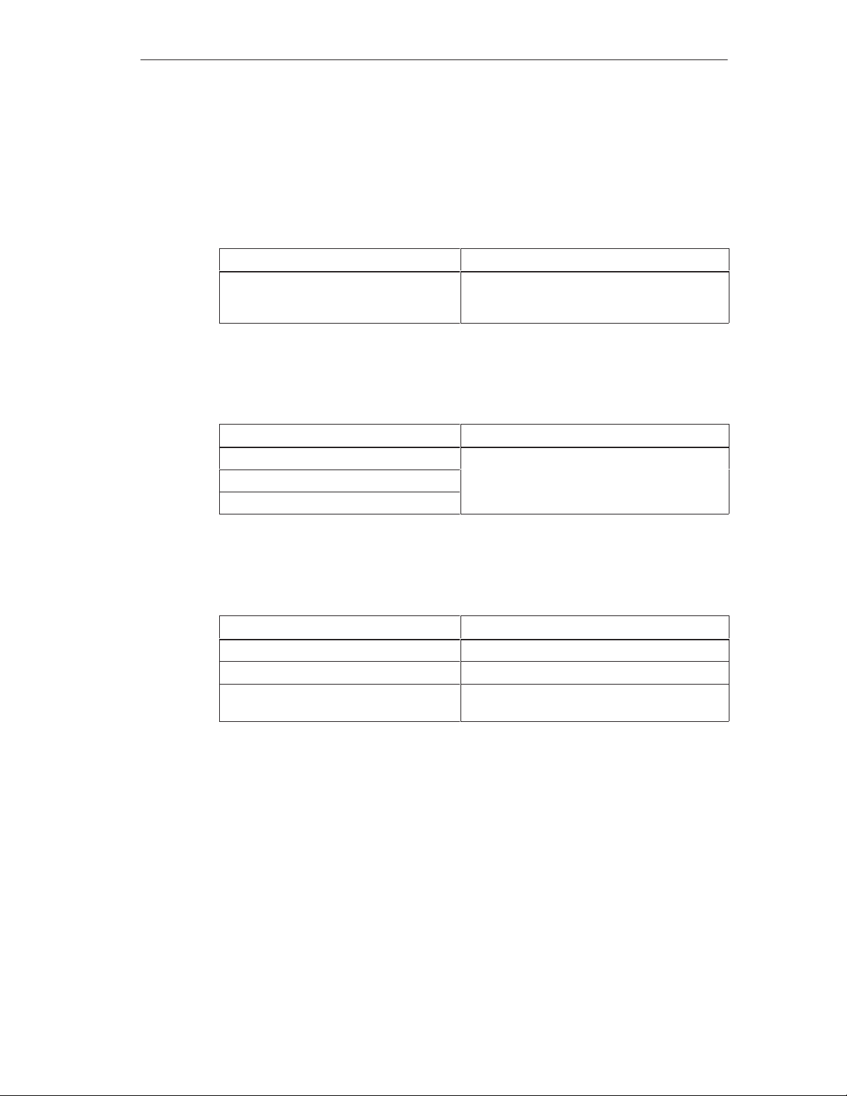
Overview of Types of Application Function Modules
Table 1-3 Overview of M7-400 Application Function Modules
Product Overview
Description
FM 456-2 application function module Pentium, 120 MHz, 16 MByte DRAM main me-
Overview of Memory Cards
Table 1-4 Overview of Memory Cards for the M7-400 Application Function Modules
Description
Flash EPROM, 4 Mbyte
Flash EPROM, 8 Mbyte
Flash EPROM, 16 Mbyte
Expansion modules
Table 1-5 Expansion Modules for the M7-400 Application Function Modules
Description
EXM 478 expansion module Provides space for 3 interface submodules
A TM 478 AT adapter module Provides space for a short A T module
MSM 478 mass storage module 3.5” diskette drive, hard disk, ”LPT1” parallel
Remarks
mory installed, 256 Kbyte SRAM with buffer,
with option of connecting expansion modules
Remarks
Memory cards with various memory capacities.
Remarks
interface
FM 456-2 Application Function Module Installation, Hardware, and Startup
C79000-G7076-C458-01
1-7
Page 18
Product Overview
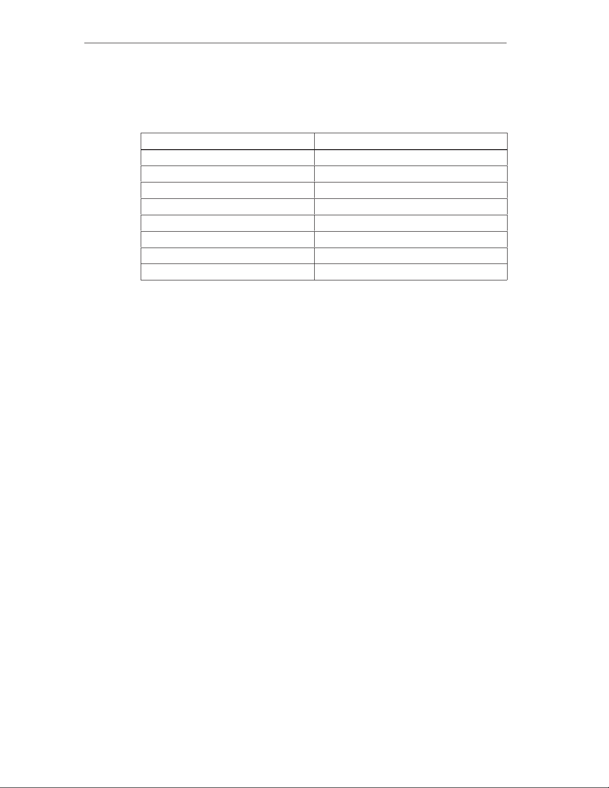
M7-400 Interface Submodules
Table 1-6 Overview of M7-400 Interface Submodules
Description
IF 961-AIO Analog input/output
IF 961-CT1 Counter connection
IF 961-DIO Digital input/output
IF 962-COM 2 serial interfaces
IF 962-LPT Printer interface
IF 962-VGA Connection for VGA monitor and keyboard
IF 964-DP SINEC L2-DP interface (Profibus)
CP 1401 TCP/IP interface
Remarks
Information about additional interface submodules can be found in the catalogs.
1-8
FM 456-2 Application Function Module Installation, Hardware, and Startup
C79000-G7076-C458-01
Page 19
Installation and Startup
This section provides you with some brief information about the necessary steps to
start up an FM 456-2.
The startup activities can be divided into several steps, which should be carried out
in the order shown:
1. Installing and switching on the hardware
2. Load operating system, adapt BIOS setup if necessary
3. Load user software into the FM 456-2 from PG/PC, test and commission. Adapt
S7/M7 software to the FM 456-2 functions.
The activities you must carry out in step 1 of the startup process are shown below
in the correct order in form of a checklist. The checklist contains notes on where
you can find detailed information on each point.
2
Refer to
startup process.
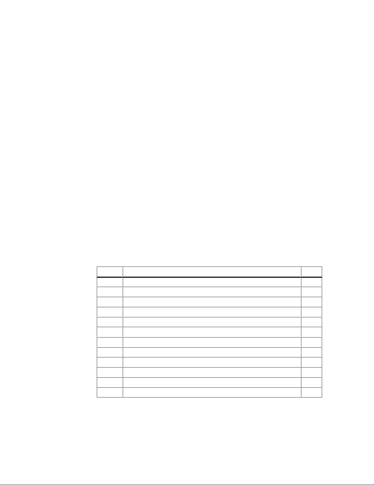
In this Chapter
Section Subject Page
2.10 Connecting the Operator Panels and Peripherals 2-21
2.1 1 Connecting a Programming Device or PC to the COM Interface 2-23
2.12 First Switch-On of the FM 456-2 2-26
manuals /2/ and /3/
2.1 Installation Checklist and Switch-on Test 2-2
2.2 Module Accessories 2-3
2.3 Installing Interface Submodules 2-4
2.4 Installing a Short A T Card 2-6
2.5 Fitting Expansion Modules to an FM 456-2 2-8
2.6 Installing a Module Assembly in the Module Rack 2-14
2.7 Inserting/Removing the Memory Card 2-18
2.8 Connecting a Module Assembly 2-19
2.9 Preparing for Operation 2-20
for information on activities in steps 2 and 3 of the
FM 456-2 Application Function Module Installation, Hardware, and Startup
C79000-G7076-C458-01
2-1
Page 20

Installation and Startup
2.1 Installation Checklist and Switch-on Test
Installation Checklist and Switch-On Test
This section explains the procedure for installing and starting up the M7-400
components step by step. Please proceed as described below:
1. Check that the power supply to the rack is correctly dimensioned.
(Chapter 2 and /1/)
2. Plug the interface modules into the FM 456-2 and the EXM 478 expansion
modules.
(Section 2.3)
3. If you want to use an ATM 478 adapter module, you must install the appropriate
short AT module in the ATM 478 before the next step.
(Section 2.4)
4. If appropriate, assemble the FM 456-2 with its expansion modules into a
complete unit before installing in the rack.
(Section 2.5)
5. Switch off the power supply (PS).
6. Fit the pre-assembled module or module assembly onto the rack and secure
with the screws.
(Section 2.6)
7. Insert the key in the operating mode switch.
(Section 2.6)
8. Connect a PG or a PC if necessary to install the system software.
(Section 2.11)
9. Connect the necessary operator equipment and peripherals.
(Section 2.10)
10.Switch on the peripherals.
11.Switch the power supply (PS) on again.
12.Check that the status and fault displays respond correctly.
(Section 2.12)
2-2
FM 456-2 Application Function Module Installation, Hardware, and Startup
C79000-G7076-C458-01
Page 21

2.2 Module Accessories
FM 456-2
EXM 478
The module packaging contains the basic accessories you need to install the
modules in the rack. There are optional accessories for some modules.
Accessories
The accessories for the modules are listed and briefly explained in Table 2-1.
Table 2-1 Accessories for the Modules
Installation and Startup
Module
-
application function
module
EXM 478
expansion module
ATM 478
A T adapter module
MSM 478
mass storage
module
Accessories
Provided
(Basic Accessories)
2 keys – The key serves to actuate the
1 module cover (fitted) – Cover for unused submodule slot
– Memory Card For storing the user program with
2 connecting clips – For fixing the EXM 478 in a
2 module covers
(fitted)
2 connecting clips – For fixing the ATM 478 in a
2 connecting clips – For fixing the MSM 478 in a
Accessories not
Provided
12 module covers
including screws
– Cover for unused submodule
Purpose of Accessories
mode switch for the FM 456-2
the FM 456-2 in the power off
condition
Covers for unused submodule
slots.
module assembly.
slot.
module assembly, top and
bottom.
module assembly, top and
bottom.
FM 456-2 Application Function Module Installation, Hardware, and Startup
C79000-G7076-C458-01
2-3
Page 22
Installation and Startup
2.3 Installing Interface Submodules
The EXM 478 expansion module has three card slots to accept interface
submodules. The FM 456-2 application function module has two card slots.
Warning
!
The modules can become damaged.
If the interface module is inserted or removed with the power on, the FM 456-2,
the expansion module or the interface submodule may be damaged.
Never insert or remove the interface submodule with the power on. Always switch
off the power supply (PS) before inserting or removing interface submodules.
Observe the ESD rules when installing an interface submodule.
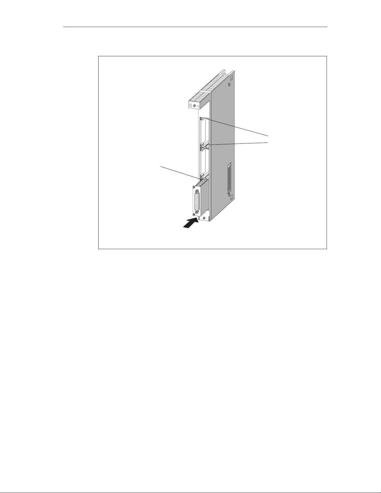
Installing Interface Submodules
Proceed as follows to install an interface submodule in a card slot:
1. Hold the interface submodule on the long sides of the front plate.
2. Insert the PCB end of the interface submodule in the upper and lower guides of
the card slot as shown in Figure 2-1.
3. Slowly push the interface submodule into the slot until the connector on the
interface submodule latches into the slot and the front plate lies flush against
the edge of the slot.
4. Secure the front plate with the two fitted, captive M2.5 x 10 slot-headed screws
on the left frame of the card slot.
Warning
!
The interface submodules and the connected equipment can become damaged.
The interface submodules and the equipment connected to them may be
destroyed if the submodules are connected to the wrong front plugs.
Label the front plugs so that the associated interface submodule can be clearly
identified.
2-4
FM 456-2 Application Function Module Installation, Hardware, and Startup
C79000-G7076-C458-01
Page 23
Frame of card slot with
mounting hole
Installation and Startup
Guides
Figure 2-1 Inserting an Interface Submodule in an Expansion Module
Covers for the Unused Card Slots
When the application function modules and expansion modules are delivered, only
the upper card slot is open. All other card slots are covered. The cover is secured
to the frame of the card slot with screws.
Slacken the screws and remove the cover to insert more than one interface
submodule in an expansion module.
EXM 478
FM 456-2 Application Function Module Installation, Hardware, and Startup
C79000-G7076-C458-01
2-5
Page 24

Installation and Startup
2.4 Installing a Short AT Card
The ATM 478 AT adapter module can accept a short AT card. An AT module can
only be installed if the ATM 478 AT adapter module is not mounted. Only short AT
cards with a slot in the mounting bracket can be installed (see also the chapter on
M7-400 expansion in the
Warning
!
The modules can become damaged.
If the interface module is inserted or removed with the power on, the FM 456-2,
the expansion module or the AT card may be damaged.
Never insert or remove the AT card with the power on. Always switch off the power
supply (PS) before inserting or removing AT cards.
Observe the ESD rules when installing an AT card.
reference manual
).
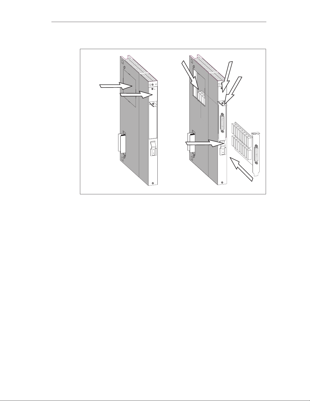
Installing the AT Card
Proceed as follows to install an AT module in an ATM 478 AT adapter module:
1. If the ATM 478 AT adapter module is installed in the rack, you must remove the
module assembly and extract the ATM 478 AT adapter module from this
assembly.
2. Remove the cover from the upper left side of the ATM 478 (see Figure 2-2).
3. Remove the mounting bracket for the AT module from the upper front of the
ATM 478 by undoing the screw (see Figure 2-2).
4. Insert the AT card into the slot from the front (see Figure 2-2).
5. Press the AT card through the side opening and at the front downward into its
connector until it engages. Ensure that the AT module support plate slides
under the metal spring on the front of the ATM 478 (see Figure 2-2).
6. Fit the mounting bracket over the angled part of the support plate of the AT card
and screw it onto the support plate of the AT card and to the ATM 478 (see
Figure 2-2).
7. Fit the cover to the upper left side of the ATM 478.
2-6
FM 456-2 Application Function Module Installation, Hardware, and Startup
C79000-G7076-C458-01
Page 25
Installation and Startup
5.
2.
3.
5.
Figure 2-2 Installing an AT card in an ATM 478 AT adapter module
6.
5.
4.
FM 456-2 Application Function Module Installation, Hardware, and Startup
C79000-G7076-C458-01
2-7
Page 26

Installation and Startup
2.5 Fitting Expansion Modules to an FM 456-2
Before installing your M7-400 in the module rack, you must pre-assemble the
FM 456-2 application function module with all necessary expansion modules.
This section provides information that you will need to pre-assemble expansion
modules, such as an EXM 478 expansion module, an ATM 478 AT adapter module
and an MSM 478 mass storage module, to an application function module to form
a module assembly.
Assembly Sequence
Carry out assembly in the following sequence:
1. Remove the covers over the plugs and sockets on the modules.
2. Remove the connecting clips that are fitted at the top and bottom of the module.
3. Remove the module covers.
4. Position the modules on a level surface and interconnect them.
5. Clip the modules together with connecting clips at the top and bottom.
The individual steps for fitting expansion modules are illustrated on the following
pages.
2-8
FM 456-2 Application Function Module Installation, Hardware, and Startup
C79000-G7076-C458-01
Page 27
Removing the Connector and the Socket Covers
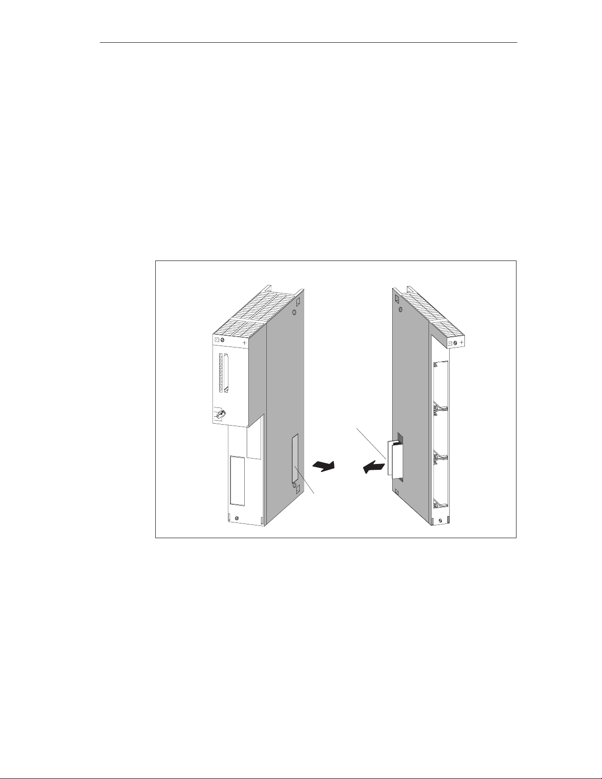
Situated on the right-hand side of the application function module is a 120-pin
socket for connecting expansion modules to the ISA bus. This socket is protected
by a screw-mounted metal cover (see Figure 2-3).
The EXM 478, ATM 478 and NSM 478 expansion modules contain
The matching connector on the left side,
An expansion socket on the right side so that other expansion modules can be
plugged in.
Remove the transport protection from the expansion plugs and the covers from the
expansion sockets of the module that are to accept other expansion modules.
Installation and Startup
Example: FM 456-2
Expansion plug
Expansion socket
Figure 2-3 Locations of the Expansion Socket and Plug with Associated Covers
Example: EXM 478
FM 456-2 Application Function Module Installation, Hardware, and Startup
C79000-G7076-C458-01
2-9
Page 28
Installation and Startup
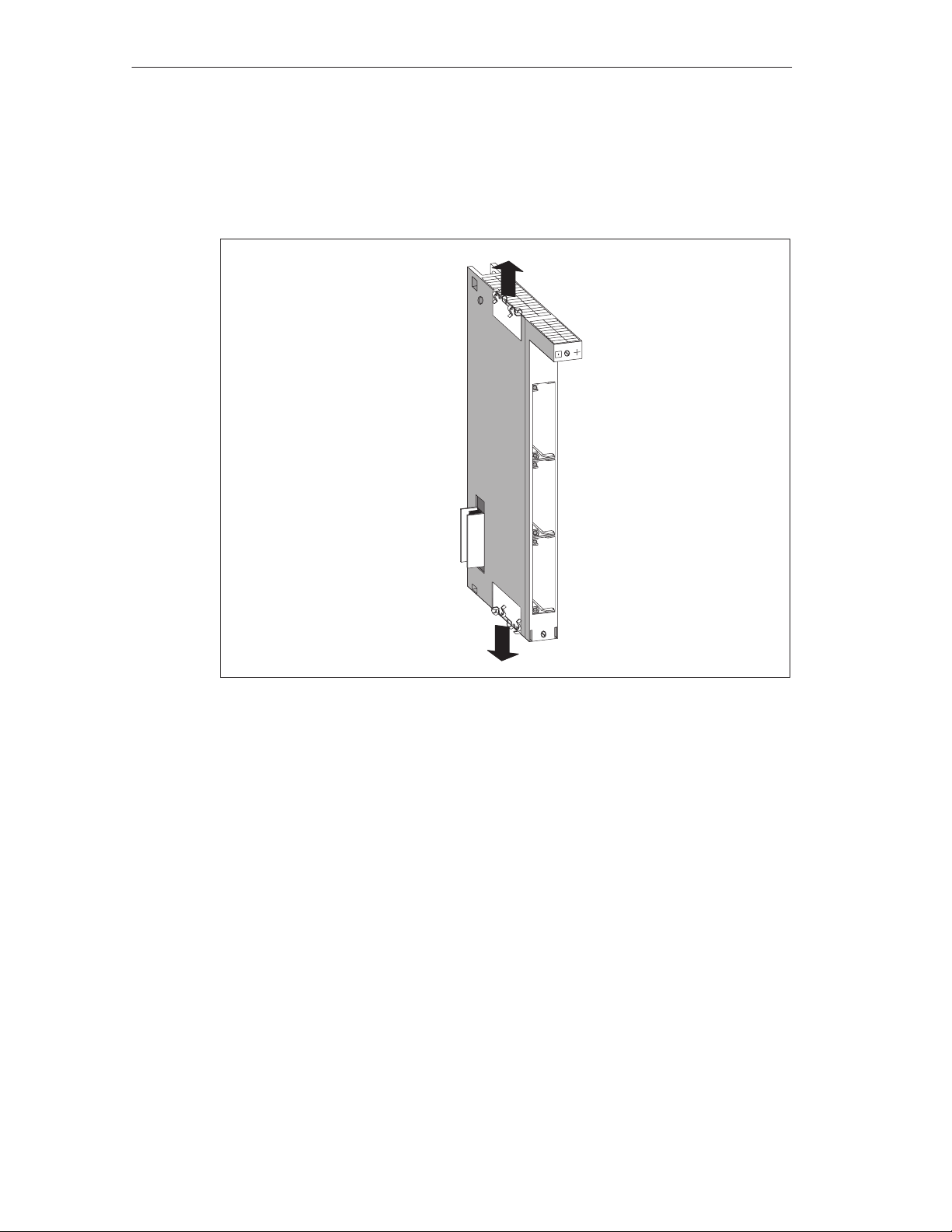
Removing the Connecting Clips
Connecting clips are fitted at the top and bottom of expansion modules. Pull these
off upward and downward respectively.
Figure 2-4 EXM 478 Expansion Module Fitted with Connecting Clips
2-10
FM 456-2 Application Function Module Installation, Hardware, and Startup
C79000-G7076-C458-01
Page 29
Removing the Cover
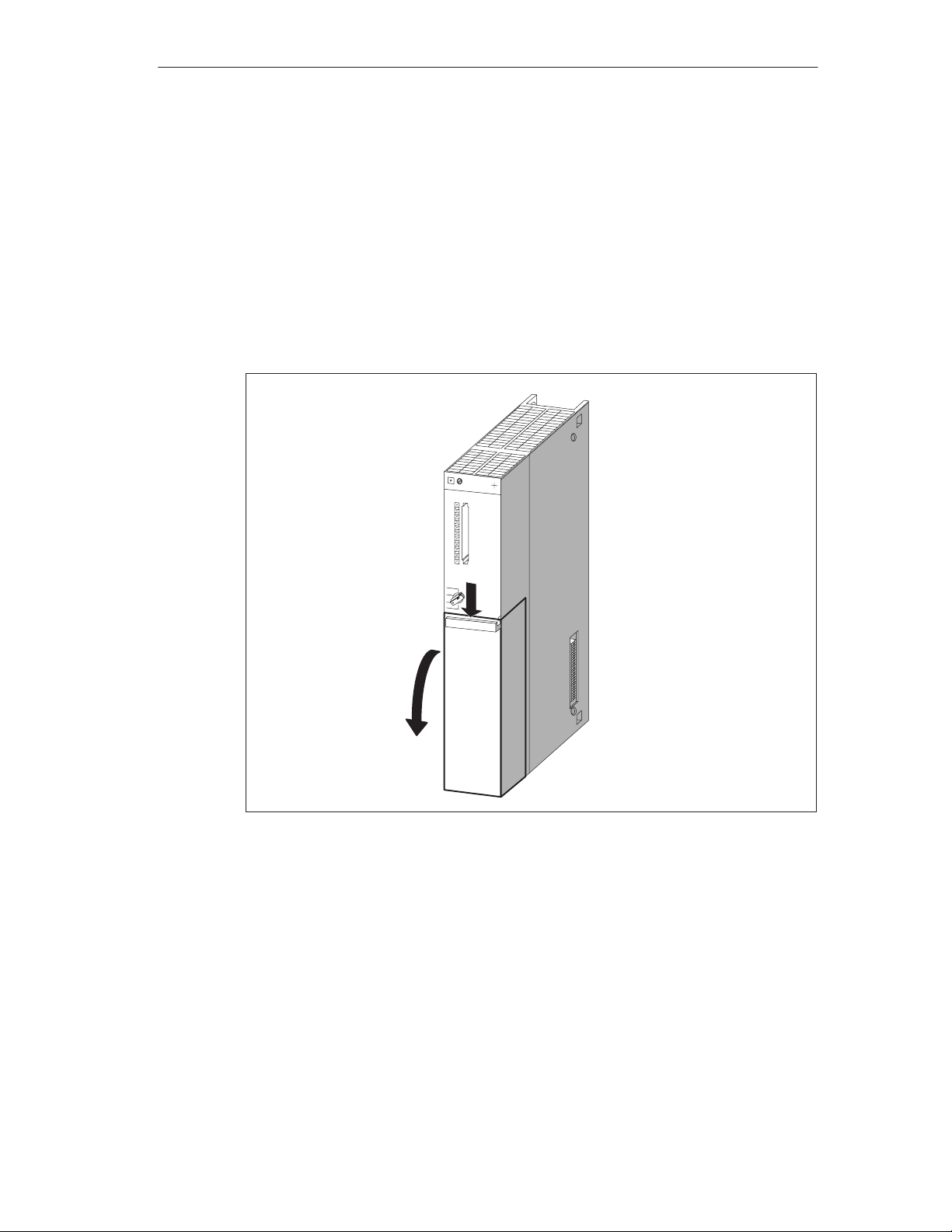
On the modules with a cover (for example FM 456-2, EXM 478 and MSM 478),
remove the cover before interconnecting the modules or fitting a module in the
rack.
Proceed as follows:
1. Press the locking lever down (1).
2. Swivel the cover forward and off (2).
Figure 2-5 shows how to remove the cover.
Installation and Startup
(2)
Figure 2-5 Removing the Cover
(1)
FM 456-2 Application Function Module Installation, Hardware, and Startup
C79000-G7076-C458-01
2-11
Page 30
Installation and Startup
Interconnecting the Modules
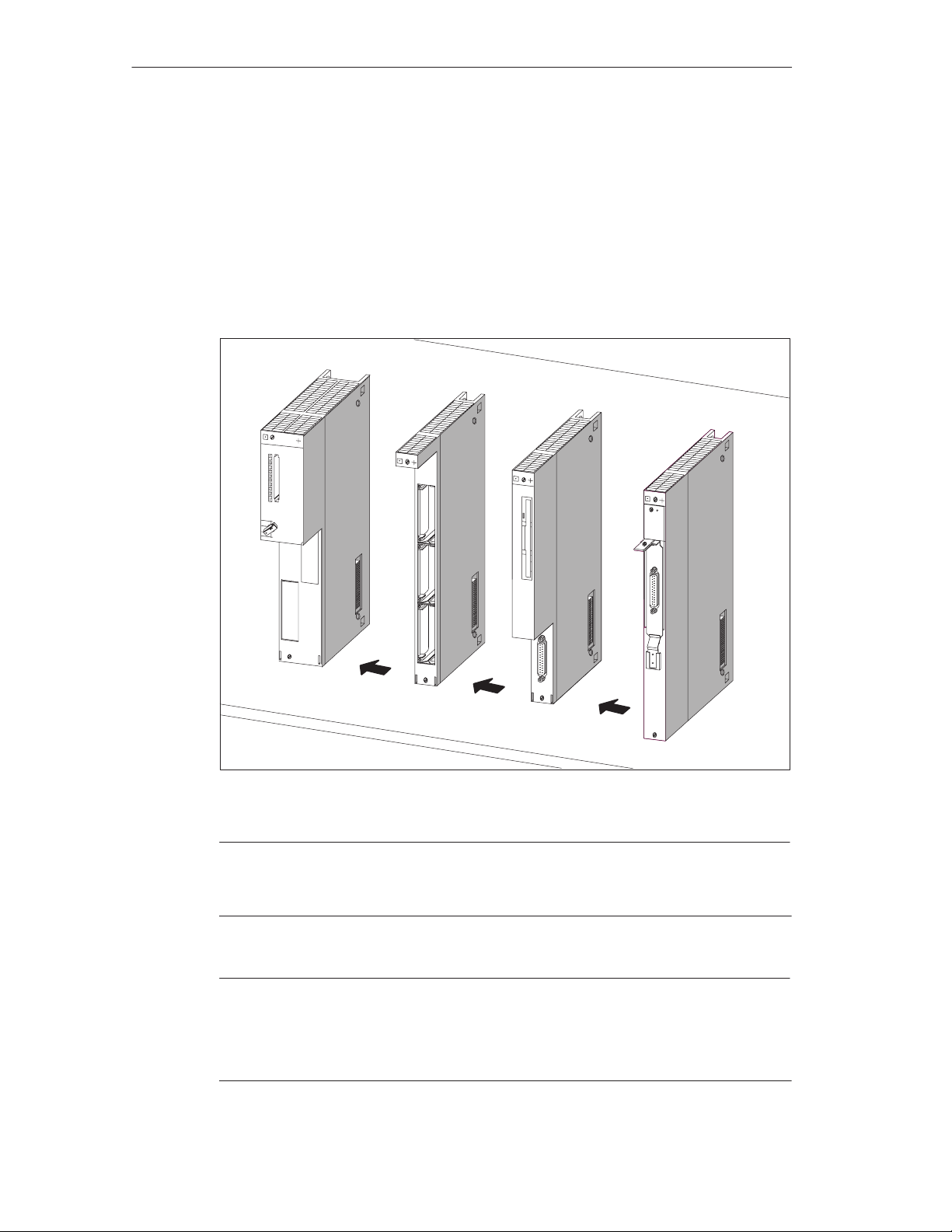
Take the application function module and first expansion module, position them on
a level surface (see Figure 2-6) and press them carefully together so that all pins
of the expansion module plug are precisely inserted into the socket on the
FM 456-2.
Then plug the other modules successively in to the assembled group (see
Figure 2-6). All the expansion modules are then connected to the ISA bus of the
application function module.
FM 456-2
EXM 478
MSM 478
ATM 478
1.
2.
Flat surface
Figure 2-6 Interconnecting an FM 456-2 and Expansion Modules
3.
Note
Only particular combinations of the expansion modules are allowed. See the chapter on M7-400 expansion in
manual /1/
, section “Permissible Combinations”.
Note
The connector pins can be damaged.
If the modules are not exactly lined up for interconnecting, the pins can be
damaged. Line up the modules precisely when interconnecting.
2-12
FM 456-2 Application Function Module Installation, Hardware, and Startup
C79000-G7076-C458-01
Page 31
Clipping the Modules Together
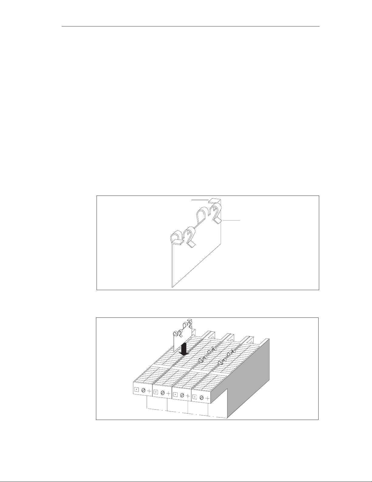
After interconnection, the modules are clipped together with the two connecting
clips provided (see Figure 2-7) to prevent twisting or loosening. This is carried out
as follows:
1. Push the connecting clip from the top between the two modules to be clipped
together as shown in Figure 2-8 so that the bent end pieces of the clip touch the
module housing cover.
2. Then position the connecting clip so that each bent end piece is above a grid
slot of the module housing cover. The first bent end piece should be above the
fifth grid slot, seen from the rear of the module.
3. Then push the two rectangularly bent end pieces of the connecting clip
downwards to clip them together. Figure 2-8 shows the connecting clips after
clipping together.
4. Carry out steps 1 to 3 in a similar manner for the bottom of the modules to be
clipped together.
Installation and Startup
Clip end bent 90
Figure 2-7 Connecting Clip
Bent clip end
Figure 2-8 Fixing the Modules Together with the Connecting Clips
FM 456-2 Application Function Module Installation, Hardware, and Startup
C79000-G7076-C458-01
2-13
Page 32

Installation and Startup
2.6 Installing a Module Assembly in the Module Rack
Installation Sequence
To install a module or module assembly in a module rack, proceed in the following
sequence:
1. Disconnect the power supply module from the mains supply.
2. Remove the blanking covers from the slots into which you wish to plug modules
(module assemblies). To do this, grasp the blanking cover at the marked
positions and pull it off towards the front.
3. Remove the cover from the module if this has not already been done.
4. Hang the module (see Figure 2-9) or the module assembly (see Figure 2-10)
onto the rack and swing it downwards without applying pressure from above (1).
5. Screw the module or all modules in a module assembly to the rack at the top
and bottom with a torque of 0.8 - 1.1 Nm (see Figure 2-11).
6. Replace the module cover(s) if necessary.
7. Insert the key in the mode switch on the FM 456-2 after all modules have been
fitted.
The individual steps for mounting the modules are illustrated in the following
pages.
Removal of the modules is described in Section 3.
Fitting the Module Onto the Rack
Fit the module or module assembly onto the rack (1) and swing it downwards
without applying pressure from above (2).
Figures 2-9 and 2-10 show how to fit a module or module assembly onto a module
rack and swing it into place.
2-14
FM 456-2 Application Function Module Installation, Hardware, and Startup
C79000-G7076-C458-01
Page 33
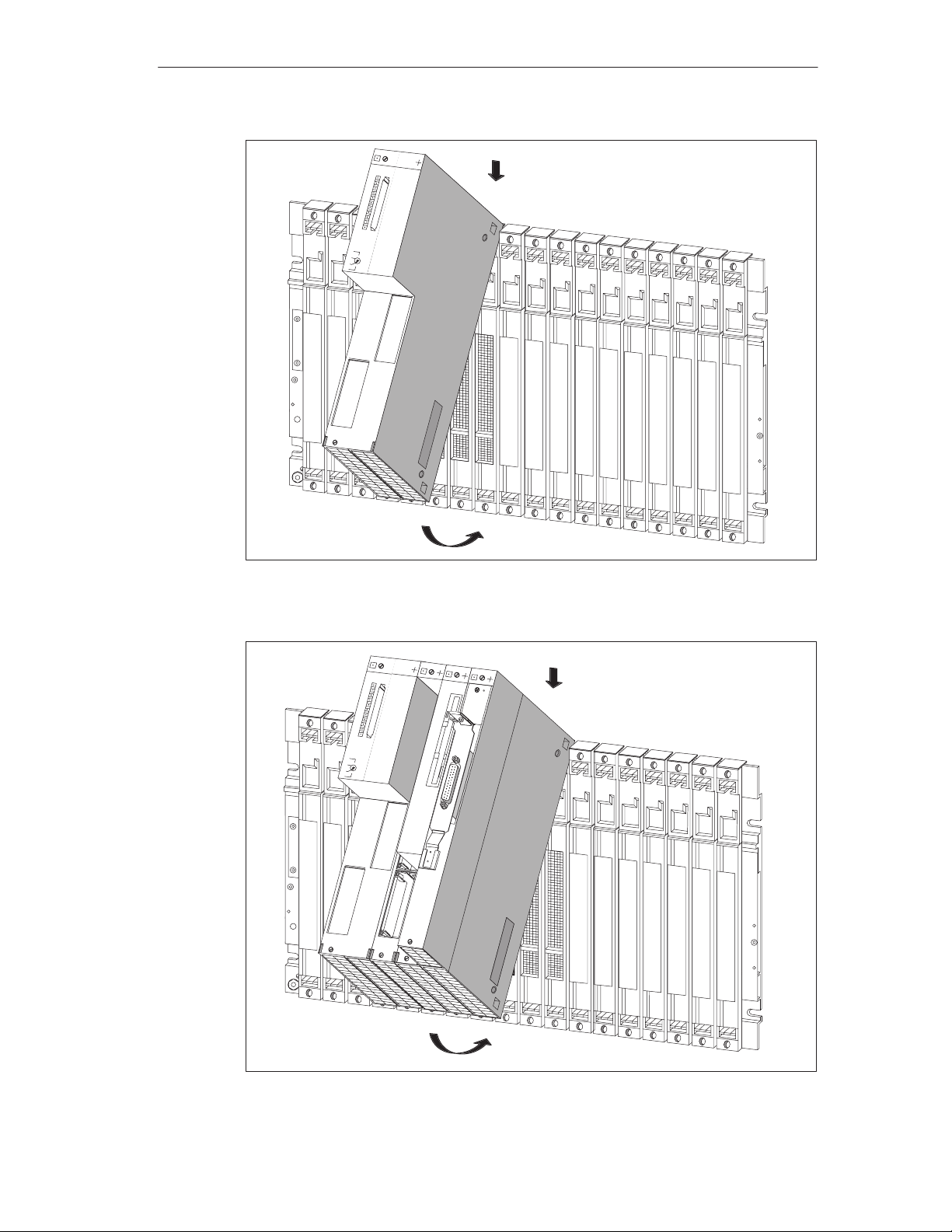
Installation and Startup
1
2
Figure 2-9 Fitting an FM 456-2 Application Function Module onto the Rack and Swinging
it into Place
1
2
Figure 2-10 Fitting a Module Assembly Consisting of FM 456-2 and Expansion Modules onto
the Rack and Swinging it into Place
FM 456-2 Application Function Module Installation, Hardware, and Startup
C79000-G7076-C458-01
2-15
Page 34
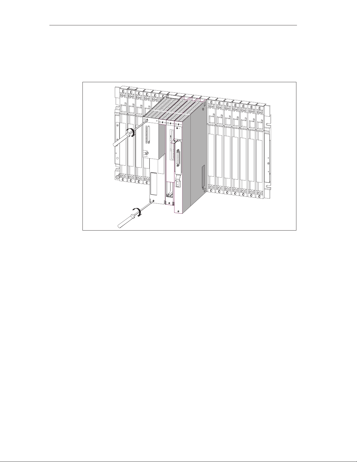
Installation and Startup
Screwing the Modules On
Figure 2-11 shows how to screw the modules on.
Tightening torque
0.8 to 1.1 Nm
Figure 2-11 Screwing the Modules On
2-16
FM 456-2 Application Function Module Installation, Hardware, and Startup
C79000-G7076-C458-01
Page 35
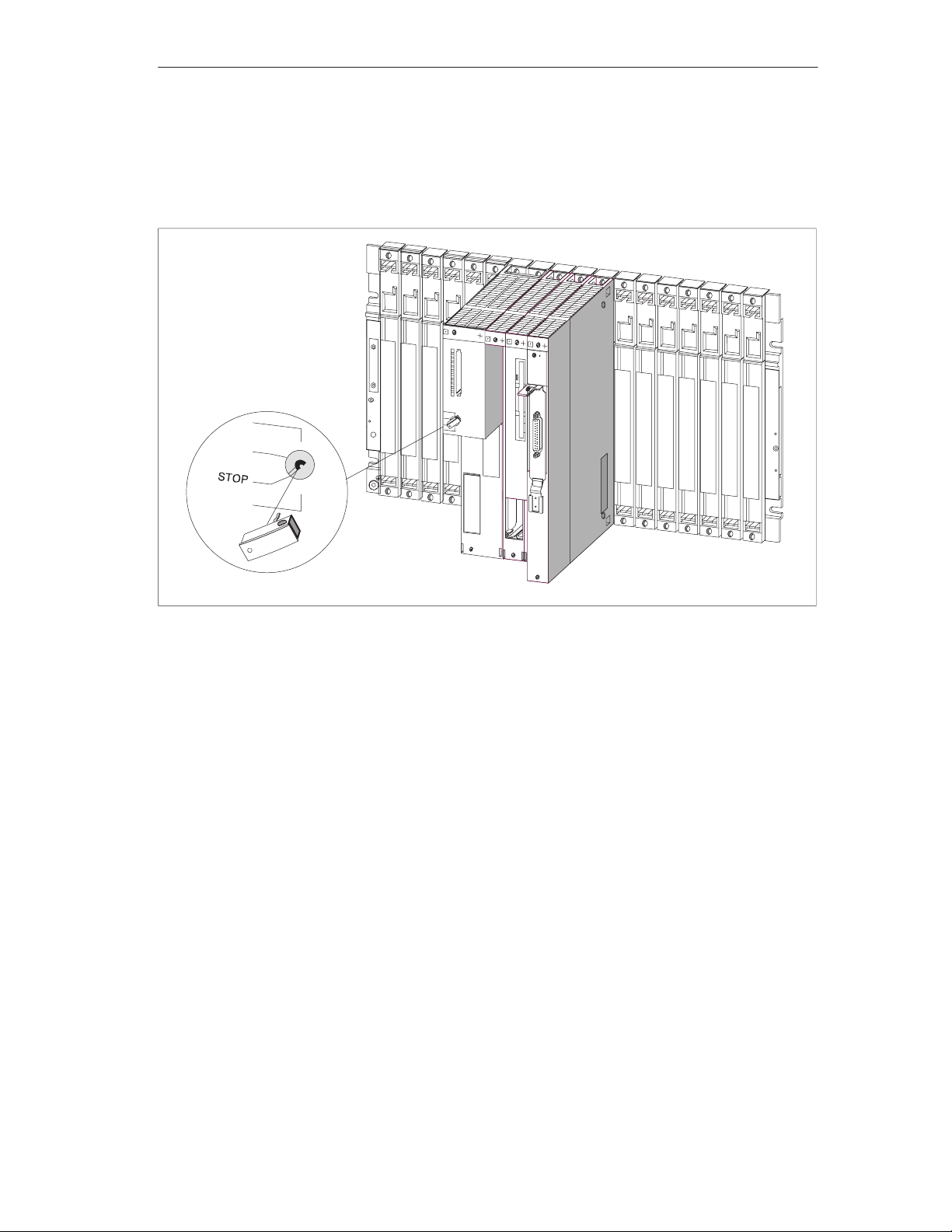
Inserting the Key in the Mode Switch
Figure 2-12 shows how to insert the key in the FM 456-2 with the switch set to
STOP. You can remove the key in the STOP or RUN settings.
Installation and Startup
Figure 2-12 Inserting the Key in the Application Function Module
FM 456-2 Application Function Module Installation, Hardware, and Startup
C79000-G7076-C458-01
2-17
Page 36
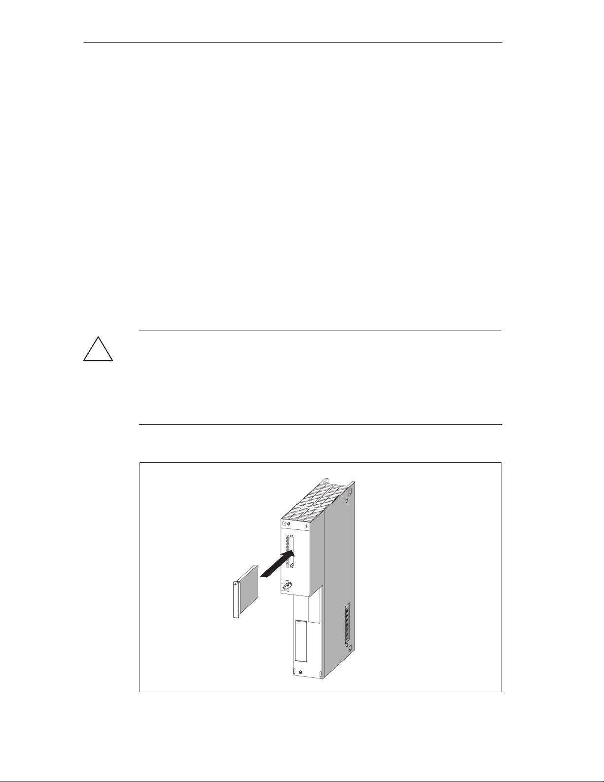
Installation and Startup
2.7 Inserting/Removing a Memory Card
Purpose of the Memory Card
By using a memory card, you can
Store the operating system, user programs and data (similar to using a
diskette);
Transport the programs and data stored on the memory card;
Retain the programs and data, even during Power Off.
Inserting/Removing the Memory Card
A memory card should only be inserted or removed when no access to the
memory card is taking place, in other words, the “SD” indicator on the FM 456-2
must be OFF. Figure 2-13 shows how to insert a memory card in an FM 456-2.
Warning
!
Data may be lost when the memory card is inserted or removed.
If write access to the memory card occurs when the memory card is being inserted
or removed, data consistency cannot be guaranteed.
If you are not certain whether write access to the memory card is still possible,
then remove it only when the power is off.
2-18
Figure 2-13 Inserting a Memory Card into an FM 456-2
FM 456-2 Application Function Module Installation, Hardware, and Startup
C79000-G7076-C458-01
Page 37

2.8 Connecting a Module Assembly
The individual modules and interface submodules of a module assembly can be
connected via commercially available cables and connectors.
Requirements
The connector housings and cables must meet the following requirements:
Connector housing: The height and width of the connector housing must not
exceed 43 mm and 19 mm respectively. It must have a 45° side outlet for the
cable. These requirements are met by the connector housings of cables and
lines listed in the chapter on spare parts and accessories of the
manual /1/
Cables: Only cables which have a braided shield may be used. The shield must
have a low-resistance connection to the housing ground.
.
Installation and Startup
reference
Components to be Connected
A module assembly can comprise the following components to be connected:
Application function module and interface submodules
EXM 478 expansion module with interface submodules
ATM 478 AT adapter module with short AT card
MSM 478 mass storage module with parallel interface
Connecting Interface Submodules
The interface submodules are equipped with subminiature D female or male
connectors. To connect devices to the interface submodules, you must fabricate
cables with the appropriate mating connectors or obtain preassembled,
commercially available cables.
The pin assignments of the subminiature D connectors can be found in the
description of the relevant interface submodule in the chapter on interface
submodules of the
reference manual /1/
Connecting the Mass Storage Module
Pin assignments of the parallel interface of the MSM 478 mass storage module
can be found in the chapter on M7-400 expansion of the
.
reference manual /1/
.
Connecting the Short AT Card
The interface pin assignments of short AT cards which you intend to use can be
found in the corresponding documentation.
FM 456-2 Application Function Module Installation, Hardware, and Startup
C79000-G7076-C458-01
2-19
Page 38

Installation and Startup
2.9 Preparing for Operation
Listed briefly in this section is information on the steps required for preparing an
FM 456-2 for operation:
You will learn
The sequence in which preparations must be made by means of a checklist
How to connect operator panels and peripherals
How to connect a programming device via the COM interface
How to check the status and error display by switching on for the first time.
All other information which is important for preparing for operation applies (except
for the reset) both to the S7-400 and M7-400 modules and is described in
installation manual /1/
Checklist for Preparing for Operation
.
You should proceed as follows:
1. Ensure that the power is switched off.
2. Insert the backup batteries in the power supply module (see
maintenance in the
3. Set the key of the mode switch to STOP.
4. Connect the required operator panels and peripherals (see
5. Switch on the peripherals.
6. Switch on the power supply (PS) of the rack.
7. Set the key of the mode switch to RUN.
8. Check that the status and error indicators are correct (see
Connecting the PROFIBUS-DP
For information on the Configuration of a PROFIBUS subnet, see Chapter 5,
“Networking” of the
see Section 8.7.6 of the
installation manual /1/
installation manual /1/)
. For starting up a PROFIBUS subnet,
installation manual /1/
Chapter 7
.
Section 2.10
Section 2.12
.
on
)
).
2-20
FM 456-2 Application Function Module Installation, Hardware, and Startup
C79000-G7076-C458-01
Page 39

Installation and Startup
Steps for Full Startup
The following steps must still be carried out for a full startup of the FM 456-2:
1. Configure your FM 456-2 with the S7 software.
2. Transfer the operating system.
3. Execute the BIOS setup.
4. Load the user software from the PG/PC to the FM 456-2, test it and start it.
A description of the BIOS setup can be found in the chapter on CPUs for the
M7-400 in the
manual
.
reference manual /1/
. For other activities, refer to the
2.10 Connecting the Operator Panels and Peripherals
The operator panels and peripherals which can be connected to your FM 456-2
depend on its configuration.
M7-SYS user
Extensive information on all connection options of the FM 456-2 can be found in
the appropriate sections of the technical data.
To prepare for operation, you need either a PC/PG or the M7-400 configuration
with monitor, keyboard, expansion module, and mass storage module as well as
interface submodules.
For reasons of noise immunity of the entire system, we recommend that you use
the standard connecting cables available from Siemens for connecting the
peripherals.
Connecting a VGA Monitor
To be able to connect a VGA monitor to the FM 456-2, an IF 962-VGA interface
submodule must be fitted in the card slot of the FM 456-2 or of a corresponding
expansion module. Connect the monitor to the 15-pin high density subminiature D
socket of the IF 962-VGA interface submodule (up to 2.5 m).
Connecting a Keyboard
Connect the keyboard to the 6-pin mini DIN circular socket on the IF 962-VGA
interface submodule
FM 456-2 Application Function Module Installation, Hardware, and Startup
C79000-G7076-C458-01
2-21
Page 40

Installation and Startup
Notes for Setting Up Monitors
Please observe the following notes when setting up monitors.
Ensure that the clearance between two monitors in asynchronous operation is
at least 15 cm, otherwise video interference may occur.
Exception: monitors with a mu-metal shield.
Provide sufficient space between the monitor and extraneous magnetic
sources.
Do not set up the monitors in steel shelving or on steel benches. Magnetization
of the surrounding sheet steel can result in false colors or video shifting.
Avoid setting up monitors in the vicinity of transformers, radio transmitters,
magnets and power cables.
The effects of extraneous magnetic fields can be attenuated by using a
mu-metal shield.
Special Conditions when Using Office Monitors
Additionally, you should observe the following notes when setting up office
monitors:
Office monitors with an internally metallized plastic housing should not be used
in an environment subject to electromagnetic interference, because the internal
metal surface cannot be subsequently connected to the external ground bus.
The required isolation of the electronics ground from the housing ground of the
monitor - essential for an environment subject to electromagnetic interference is not possible with most office monitors.
You can only use such monitors in conjunction with conventional VGA cables.
Connection to the M7-400 is therefore only possible with limitations, because
you can only cover short distances with these cables.
Connecting Printers
You can connect printers with a serial or parallel interface.
A printer with a parallel interface should be connected with the appropriate
connecting cable (see ordering information) to the IF 962-LPT interface
submodule.
A printer with a serial interface should be connected with the appropriate cable
(see ordering information) to the COM interface submodule.
We recommend the use of Siemens printers.
2-22
Note
Only a connection cable with screen grounded at both ends may be used to
connect between an M7-400 component and a printer.
FM 456-2 Application Function Module Installation, Hardware, and Startup
C79000-G7076-C458-01
Page 41
Connecting a Mouse
Connect the mouse to the IF 962-COM interface module.
A PS2 mouse must not be connected separately. If a PG keyboard is connected,
the trackball occupies the PS2-mouse interface.
Maximum Cable Lengths
Given in the table are the maximum cable lengths for connecting the individual
devices. A precondition is a hardware configuration with interference immunity.
Table 2-2 Maximum Cable Lengths for Operator Panels and Peripherals
Installation and Startup
Device
Keyboard via
Maximum Length
2.5 m (8 ft. 3 in.)
IF 962-VGA
Monitor (connection via VGA cable) via
25 m (82 ft.)
IF 962-VGA
Printer via
3 m (10 ft.)
IF 962-LPT (parallel interface)
RS232 interface e.g. terminal, printer
10 m (33 ft.)
IF 962-COM
2.11 Connecting a Programming Device or PC to the COM Interface
If you operate your FM 456-2 without monitor, keyboard and mass storage, you
need a PG or a PC to install the software. You can find out how to install this
software from the
Connecting an FM 456-2 to the PG or to a PC via the COM interface
Connect the 9-pin subminiature D connector of the COM port on your IF 962-COM
interface module to the connector of a free COM port on your PG/PC. The
following methods of connection may be used:
M7-SYS manual
.
Connection using control cables
Connection without control cables
FM 456-2 Application Function Module Installation, Hardware, and Startup
C79000-G7076-C458-01
2-23
Page 42
Installation and Startup
Connection with Control Cables
When the interface control cables are used for data traffic via the COM interface,
you need a null modem cable.
This may be necessary when, for example, you enter a console divert in the
autoexec.bat of your FM 456-2.
:
CTTY COM1
:
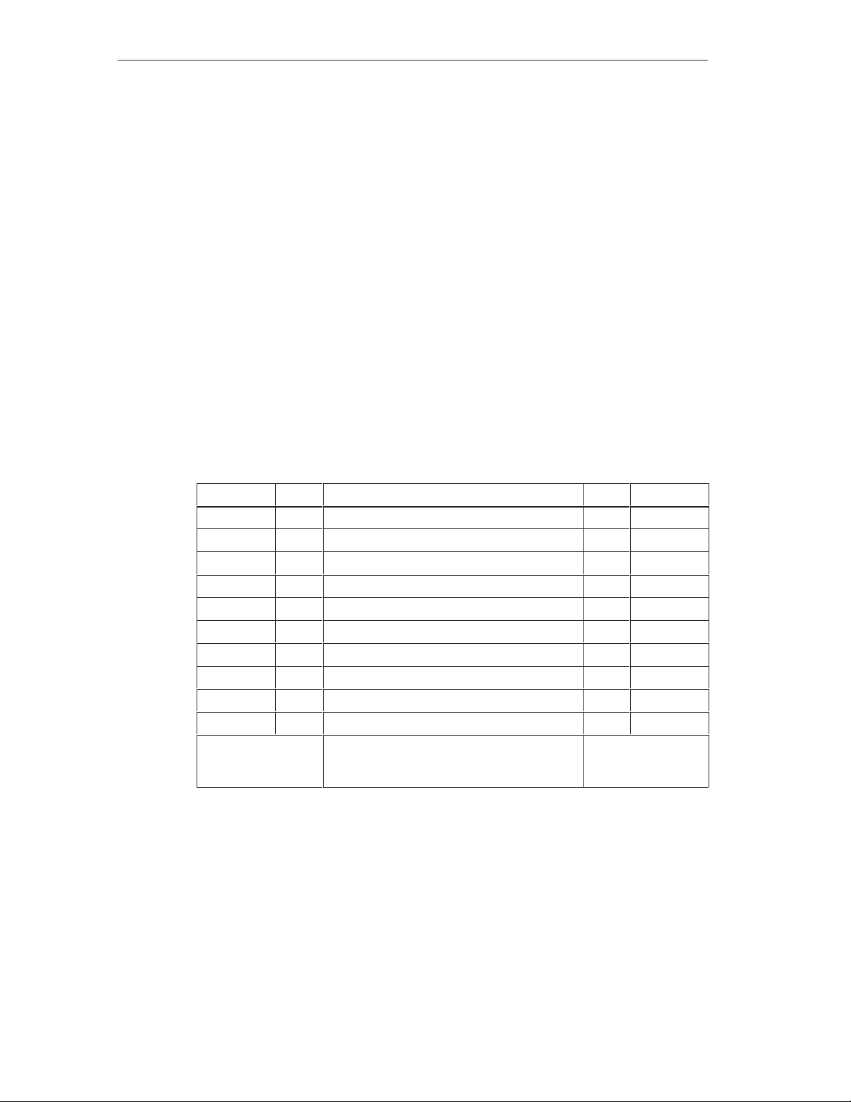
If the free COM interface of your PG/PC has a 9-pin subminiature D connector,
you can use Table 2-3 below for the pin assignments of the null-modem cable.
This cable can also be procured pre-assembled (see V.24 cables in Chapter 5,
ordering information).
Table 2-3 “Null-modem” Connector Cable for Connecting FM 456-2 via IF 962-COM to the
COM Port of a PG/PC using a 9-Pin Sub-D Connector
Signal Pin Connection Pin Signal
E1 / GND U Connected to U E1 / GND
M5 / DCD 1 _ 1
D2 / RxD 2 Connected to 3 D1 / TxD
D1 / TxD 3 Connected to 2 D2 / RxD
S1 / DTR 4 Connected to 6 M1 / DSR
E2 / GND 5 Connected to 5 E2 / GND
M1 / DSR 6 Connected to 4 S1 / DTR
S2 / RTS 7 Connected to 8 M2 / CTS
M2 / CTS 8 Connected to 7 S2 / RTS
M3 / RI 9 _ 9 M3 / RI
9-pin Sub-D socket
(COM1 to
IF 962-COM)
Pin “U” = housing (screen)
Length: maximum 10 m (33 ft.)
9-pin Sub-D socket
(COMx on PG/PC)
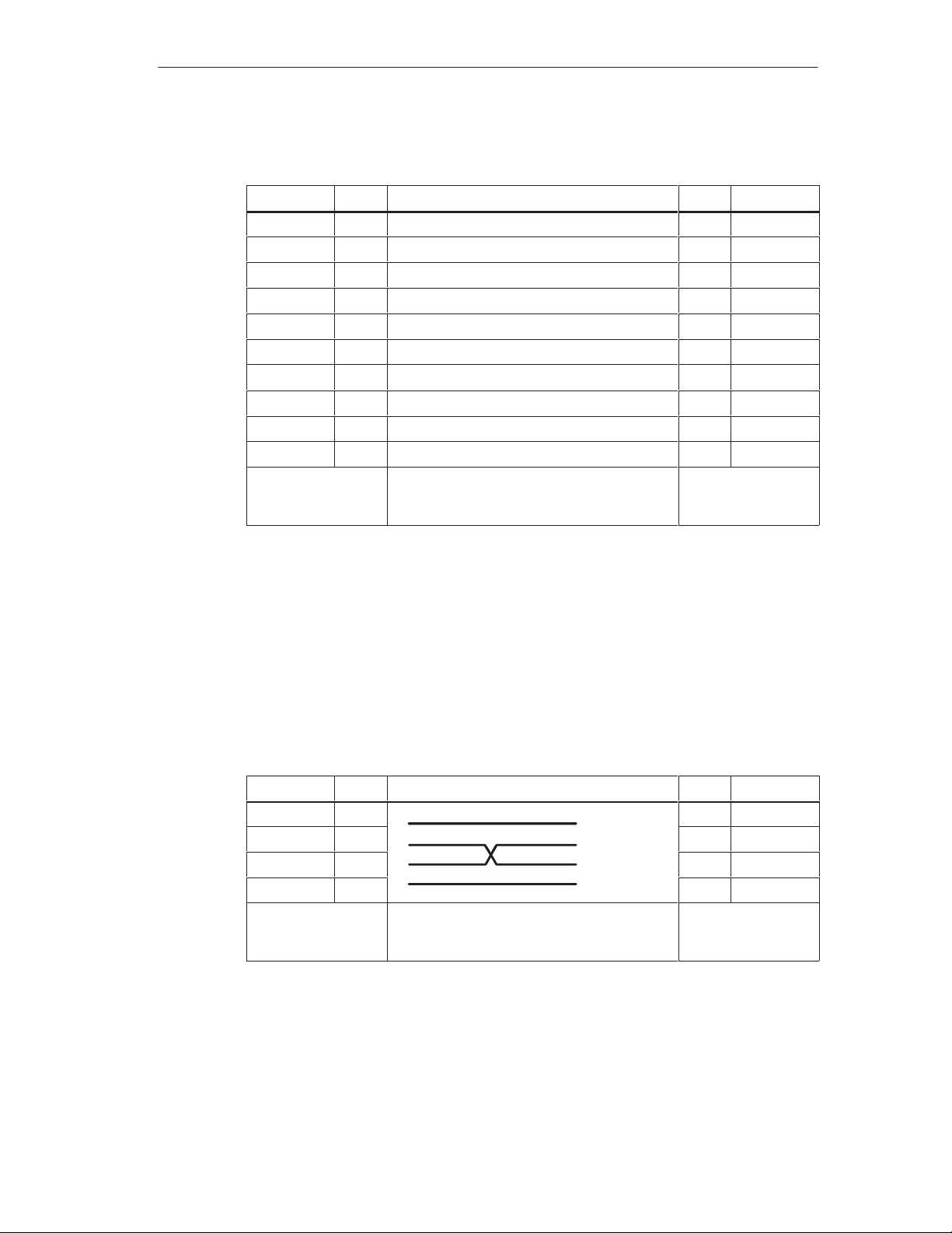
If the free COM interface of your PG/PC has a 25-pin Sub-D socket, you can use
Table 2-4 below for the pin assignments of the null-modem cable.
2-24
FM 456-2 Application Function Module Installation, Hardware, and Startup
C79000-G7076-C458-01
Page 43
Installation and Startup
Table 2-4 “Null-modem” Connector Cable for Connecting FM 456-2 via IF 962-COM to the
COM Port of a PG/PC using a 25-Pin Sub-D Socket
Signal Pin Connection Pin Signal
E1 / GND U Connected to U E1 / GND
M5 / DCD 1 _
D2 / RxD 2 Connected to 2 D1 / TxD
D1 / TxD 3 Connected to 3 D2 / RxD
S1 / DTR 4 Connected to 6 M1 / DSR
E2 / GND 5 Connected to 7 E2 / GND
M1 / DSR 6 Connected to 20 S1 / DTR
S2 / RTS 7 Connected to 5 M5 / CTS
M2 / CTS 8 Connected to 4 S2 / RTS
M3 / RI 9 _ 22 M3 / RI
9-pin Sub-D socket
(COM1 to
IF 962-COM)
Pin “U” = housing (screen)
Length: maximum 10 m (33 ft.)
25-pin Sub-D
connector
(COMx on PG/PC)
Connection Without Control Cables
If the data traffic via the COM interface is to be controlled exclusively via the data
lines, a connecting cable as described below is sufficient for connecting your
FM 456-2 to a PG/PC.
If the free COM interface of your PG/PC has a 9-pin Sub-D connector, you can use
Table 2-5 for the pin assignments of the connecting cable.
Table 2-5 Pin Assignments of the Cable for Connecting an FM 456-2 via IF 962-COM to
the COM Interface of a PG/PC with 9-pin Sub-D Connector
Signal
E1 / GND U U E1 / GND
D2 / RxD 2 2 D2 / RxD
D1 / TxD 3 3 D1 / TxD
E2 / GND 5 5 E2 / GND
9-pin Sub-D socket
(COM1 to
IF 962-COM)
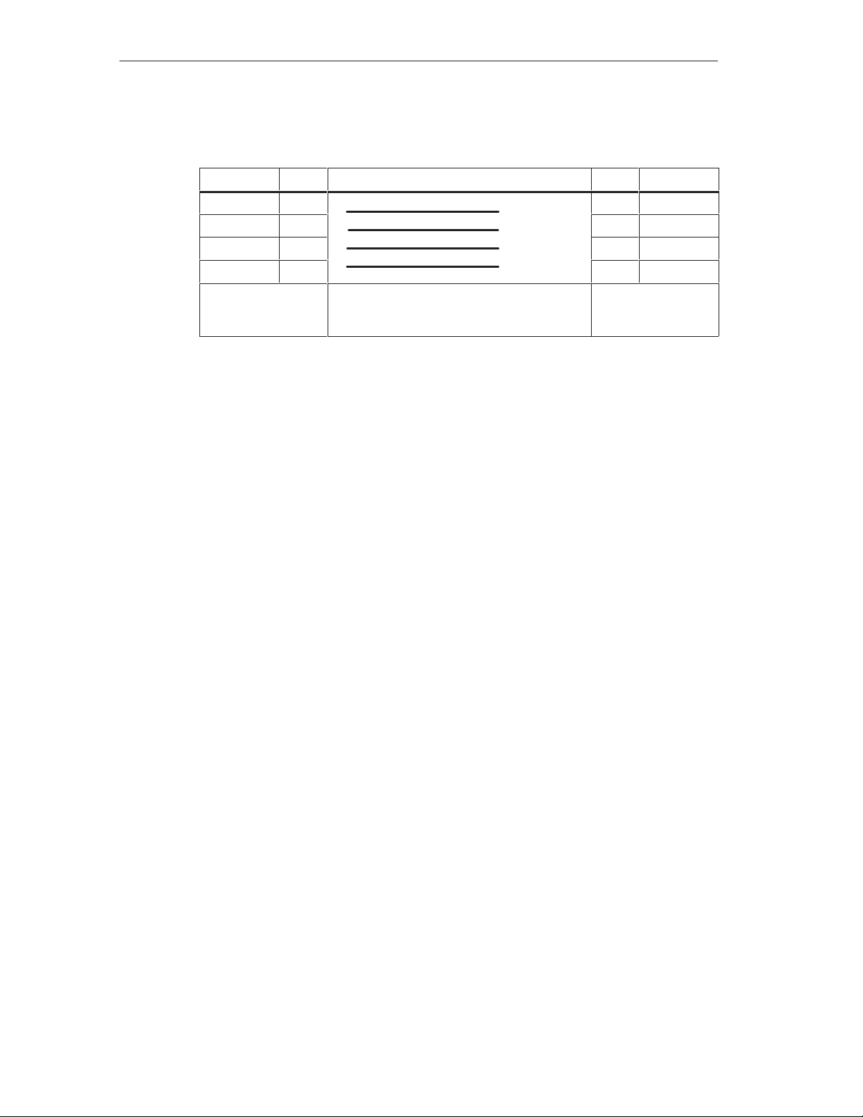
If the COM interface of your PG/PC has a 25-pin Sub-D socket, you can use
Table 2-6 for the pin assignments of the connecting cable.
Pin Connection Pin Signal
Pin “U” = housing (screen)
Length: maximum 10 m (33 ft.)
9-pin Sub-D socket
(COMx on PG/PC)
FM 456-2 Application Function Module Installation, Hardware, and Startup
C79000-G7076-C458-01
2-25
Page 44
Installation and Startup
Table 2-6 Pin Assignments of the Cable for Connecting an FM 456-2 via IF 962-COM to
the COM Interface of a PG/PC with 25-pin Sub-D Socket
Signal Pin Connection Pin Signal
E1 / GND U U E1 / GND
D2 / RxD 2 2 D1 / TxD
D1 / TxD 3 3 D2 / RxD
E2 / GND 5 7 E2 / GND
9-pin Sub-D socket
(COM1 to
IF 962-COM)
Pin “U” = housing (screen)
Length: maximum 10 m (33 ft.)
2.12 Switching On the FM 456-2 for the First Time
When the supply voltage is switched on, all status and error indicators of the
FM 456-2 light up briefly. If the mode switch is set to STOP, the STOP status/error
indicator lights up after switching on. Otherwise the module boots up. In the event
of a fault, the INTF indicator lights up.
25-pin Sub-D
connector
(COMx on PG/PC)
If this does not happen with your module, please consult your Siemens contact at
a maintenance and repair center or the SIMATIC Hotline.
The preparation for operation is now completed within the scope of this manual.
You will find the further startup steps, for instance installation of the operating
system and the user program, in the
M7-SYS
manual.
2-26
FM 456-2 Application Function Module Installation, Hardware, and Startup
C79000-G7076-C458-01
Page 45

Replacing Modules
This chapter tells you how to replace interface submodules, application function
modules or expansion modules and short AT modules. All other important
information for replacing modules applies to both S7-400 and M7-400 modules and
is described in
Warning
!
The modules can be damaged.
If interface submodules are inserted or removed with power applied, the
application function module, expansion modules and interface submodules can be
damaged.
Never insert or remove interface submodules with power applied. Always switch
off the power supply (PS) before inserting or removing interface submodules.
Observe the ESD rules when inserting or removing M7 modules and interface
submodules.
Note
manual /1/
3
.
No module in the S7-400 system may be replaced while data is being exchanged
via the MPI interface of the S7/M7-400 CPU!
Pull out the plug on the MPI interface if you are not certain!
Tool
You will require a cylindrical screwdriver with 3.5 mm wide blade for replacing the
modules and memory submodule.
In this Chapter
Section Subject Page
3.1 Replacing the Interface Submodules 3-2
3.2 Replacing an Application Function Module or Expansion Module in a
Module Assembly
3.3 Replacing the Short A T Module 3-9
FM 456-2 Application Function Module Installation, Hardware, and Startup
C79000-G7076-C458-01
3-4
3-1
Page 46

Replacing Modules
3.1 Replacing the Interface Submodule
Removing the Interface Submodule
You can replace the interface submodule with another without removing the
associated application function module or expansion module. To do this, proceed
as described below:
1. Switch the central module and all function modules in your S7/M7-400 system
to STOP with the key switch.
2. Switch off the load supply voltage to the modules.
3. Set the standby switch on the power supply module to the position (output
voltage 0 volts).
4. Loosen the screws retaining the Sub-D connectors and pull out all plugs.
5. Loosen the two captive slotted screws fixing the front plate of the interface
submodule to the left hand frame of the module card slot sufficiently to pull
these out about 6 mm (1/4 inch).
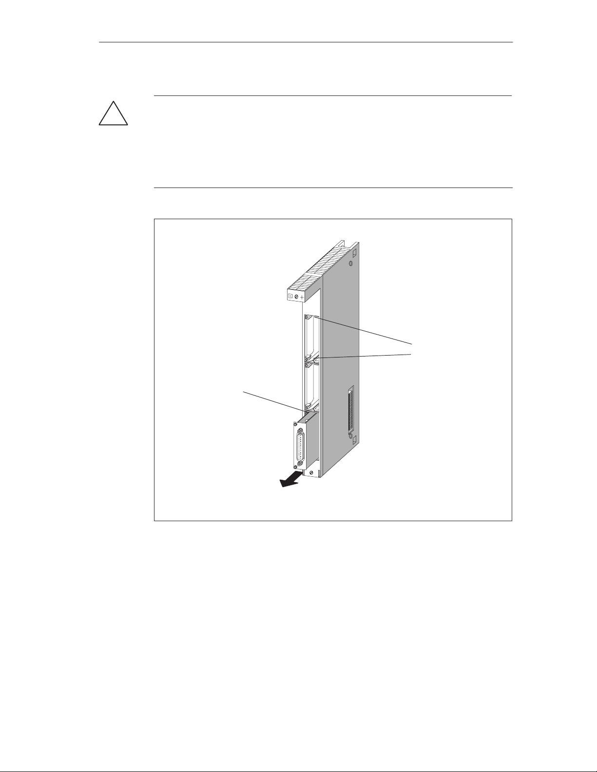
6. Pull the interface submodule carefully out of the guide of the card slot (see
Figure 3-1).
Caution
!
There is the risk of injury to persons and damage to property.
As the surface temperature of the modules can reach up to 70 °C, there is the risk
of burning. Therefore always grasp the front plate of the interface module at the
long sides.
Interface modules contain electrostatically sensitive devices which can be
damaged when being touched.
Observe the ESD rules when fitting the interface modules.
3-2
FM 456-2 Application Function Module Installation, Hardware, and Startup
C79000-G7076-C458-01
Page 47
Replacing Modules
Warning
!
The interface submodules and the connected equipment can be damaged.
When you replace several interface modules simultaneously and you mix up the
front plugs, the interface modules can be damaged.
Label the front plugs so that the associated interface submodule can be clearly
identified.
Frame of card slot with
mounting hole
Figure 3-1 Pulling the Interface Submodule out of the Card Slot of an Expansion Module
Fitting the Interface Submodule
Fit the new interface submodule in the reverse order. Further information can be
found in Section 2.3, “Installing Interface Submodules” on page 2-4.
Guides
EXM 478
FM 456-2 Application Function Module Installation, Hardware, and Startup
C79000-G7076-C458-01
3-3
Page 48
Replacing Modules
3.2 Replacing an Application Function Module or Expansion Module in a Module Assembly
Removing the Module
Proceed as follows to remove a module from a module assembly:
1. Switch the central module and all function modules in your S7/M7-400 system
to STOP with the key switch.
2. Switch off the load supply voltage to the modules.
3. Set the standby switch on the power supply module to the position (output
voltage 0 volts).
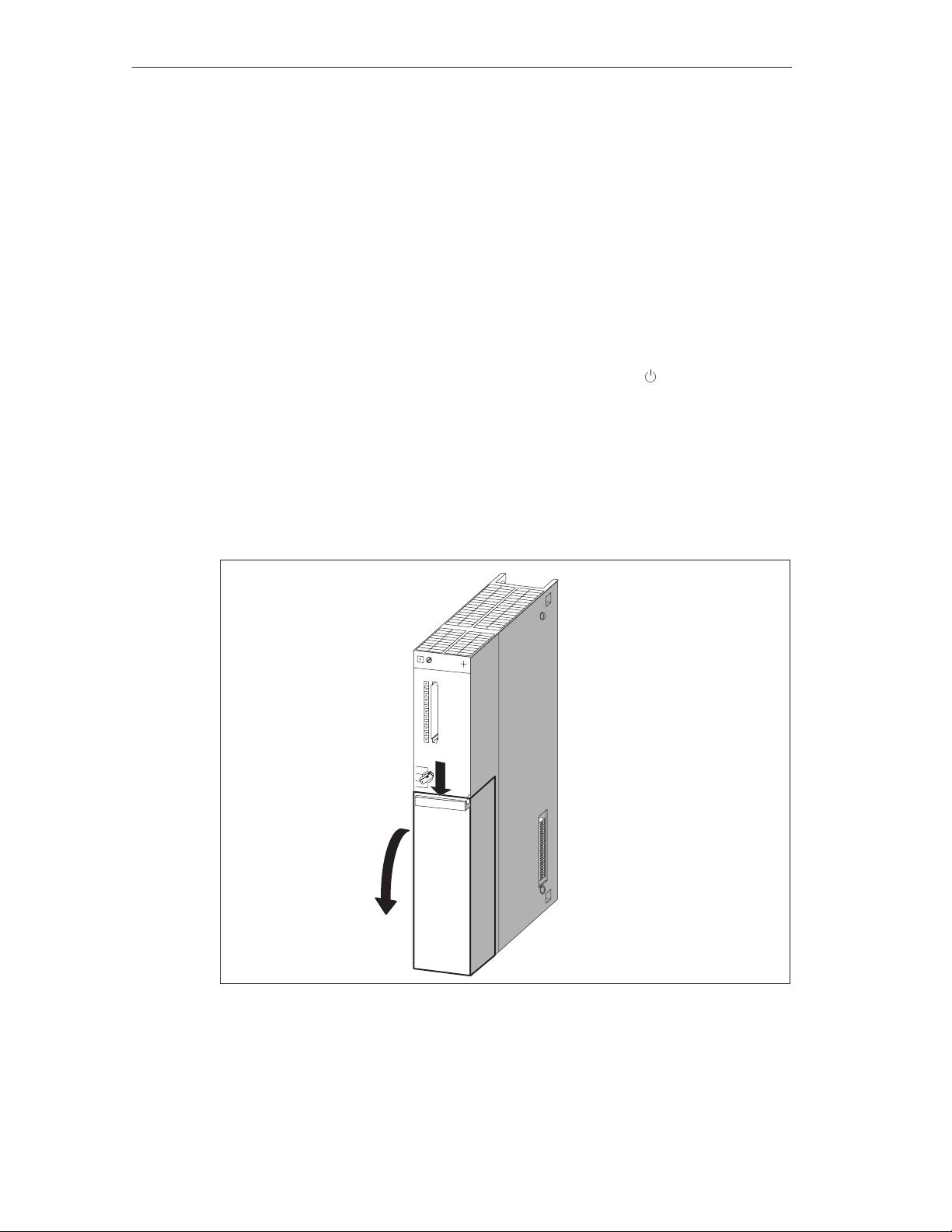
4. If necessary, remove the covers from the modules. Figure 3-2 shows how to
remove the cover.
– Press the locking lever downwards (1).
– Swing the cover off forwards (2).
3-4
(1)
(2)
Figure 3-2 Removing the Cover
5. Unplug the interface module connectors from the module group, including those
to all interface submodules.
FM 456-2 Application Function Module Installation, Hardware, and Startup
C79000-G7076-C458-01
Page 49
Replacing Modules
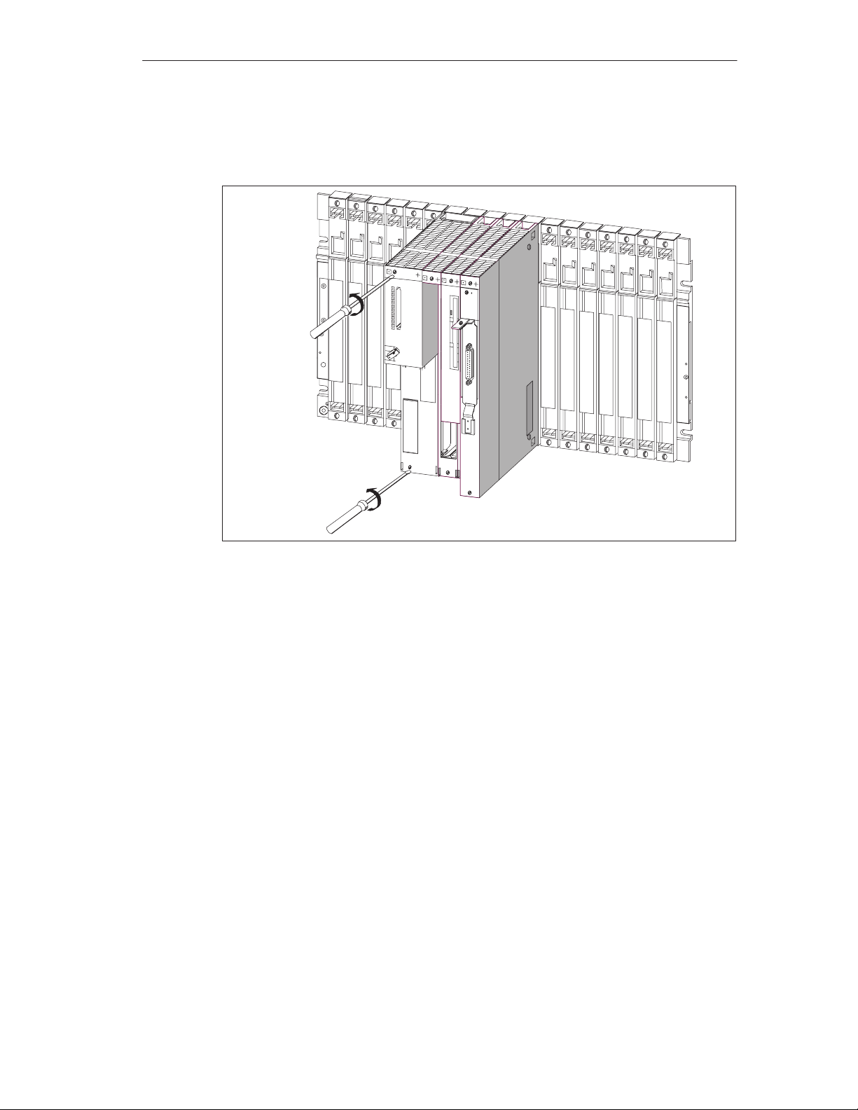
6. Undo the fixing screws on the module or module group. Figure 3-3 shows the
position of the fixing screws on a module.
Tightening Torque
0.8 to 1.1 Nm
Figure 3-3 Unscrewing the Modules
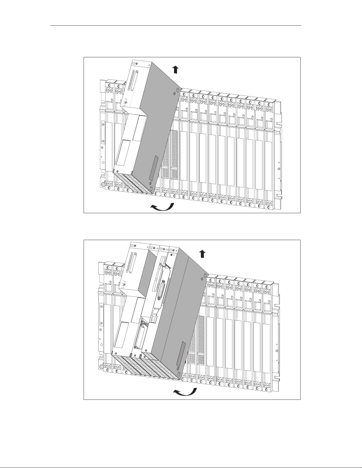
7. Swing out the module group and remove it upwards (Figures 3-4 and 3-5).
FM 456-2 Application Function Module Installation, Hardware, and Startup
C79000-G7076-C458-01
3-5
Page 50
Replacing Modules
2
1
Figure 3-4 Swinging the Module Group Out and Removing Upwards
2
3-6
1
Figure 3-5 Swinging the Module Group with FM Module and Expansion Modules Out and
Removing Upwards
FM 456-2 Application Function Module Installation, Hardware, and Startup
C79000-G7076-C458-01
Page 51
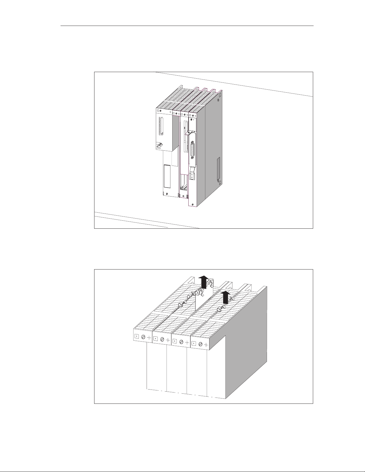
8. Place the module group on a flat surface (Figure 3-6).
Replacing Modules
Flat surface
Figure 3-6 Module Group with Application Function Module and Expansion Modules
9. Remove the left and right connecting clips from the top and bottom of the
module assembly (Figure 3-7).
Figure 3-7 Remove the Connecting Clips Between the Modules
FM 456-2 Application Function Module Installation, Hardware, and Startup
C79000-G7076-C458-01
3-7
Page 52
Replacing Modules
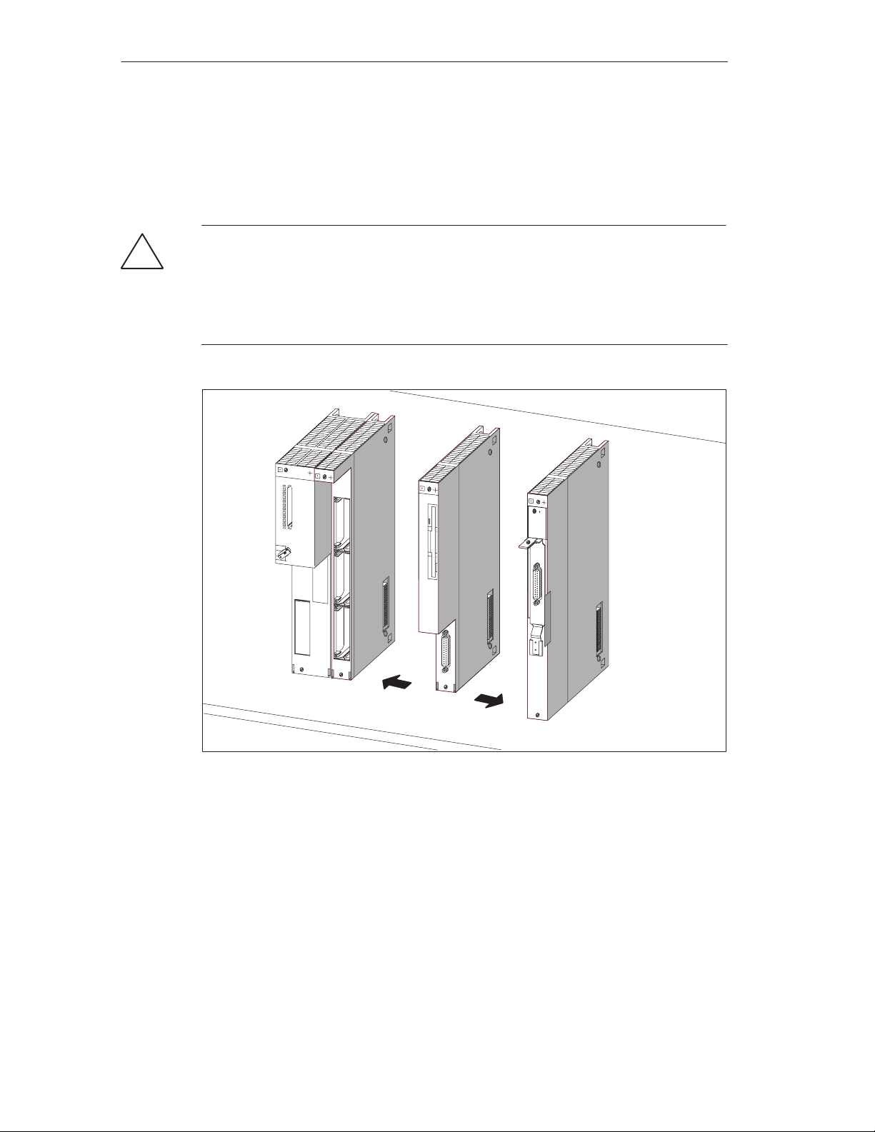
10.Pull the adjoining modules carefully away from the module to be replaced.
When doing so, hold the modules to be separated above the bus connectors
and pull them apart at the module sides, so that the ISA bus-connection is
disconnected (Figure 3-8).
Warning
!
The plug pins can be damaged.
If the modules are not kept aligned while pulling them apart, the plug pins may be
damaged.
Keep the modules aligned when pulling them apart.
Figure 3-8 Pulling the Modules Apart, For Example to Replace the Mass Storage Module
Installing the Module
Fit the new module in the reverse order. Further information can be found in
Section 2.5 “Fitting Expansion Modules to an FM 456-2” and 2.6 “Installing a
Module Assembly in the Module Rack”.
3-8
1.
FM 456-2 Application Function Module Installation, Hardware, and Startup
2.
Flat surface
C79000-G7076-C458-01
Page 53

Behavior of the M7-400 After Changing a Module
If no fault is present, the central module goes into the RUN mode following
replacement of a module. If the central module remains in the STOP mode, you
can display the cause of the fault with STEP 7 (see
Note
If data media such as Memory Card or hard disk have been renewed when
replacing a module, it may be necessary to carry out the BIOS setup again,
re-install the operating system, user programs etc. (see the appropriate section of
the
M7-SYS
user manual).
3.3 Replacing the Short AT Module
STEP 7
Replacing Modules
user manual).
Removing the AT Module
Before you can remove a short AT module, you must remove the module assembly
and take the ATM 478 AT adapter module out of the assembly (see Section 3.2,
Page 3-4).
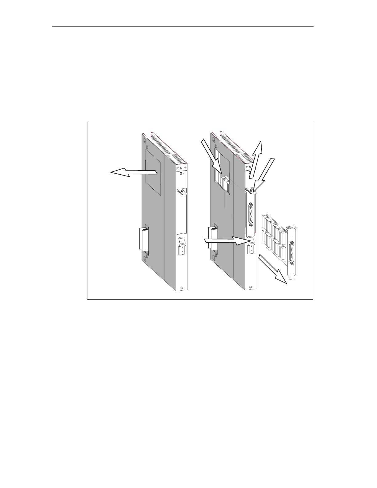
Then proceed as follows (see Figure 3-9):
Warning
!
The modules can be damaged.
If AT modules are inserted or removed with power applied, the application function
module, expansion modules and AT modules can be damaged.
Never insert or remove AT modules with power applied. Always switch off the
power supply (PS) before inserting or removing AT modules.
Observe the ESD rules when inserting or removing AT modules.
1. Remove the cover from the top left hand side of the ATM 478 (see Figure 3-9).
2. Unscrew and remove the fixing bracket from the AT module carrier plate (see
Figure 3-9).
3. Push the AT module slightly upwards (3.) so that its carrier plate slides out from
under the retaining spring (4.) on the front of the ATM 478. Then pull the AT
module upwards out of its connector, grasping it from the front and through the
side opening (see Figure 3-9).
4. Pull the AT module out of its slot from the front (see Figure 3-9).
FM 456-2 Application Function Module Installation, Hardware, and Startup
C79000-G7076-C458-01
3-9
Page 54
Replacing Modules
Installing the AT Module
Install the new AT module in the AT adapter module in the reverse order (see
Section 2.4 “Installing a Short AT Card”).
Then reinstall the AT adapter module in the module assembly and refit this to the
rack (see Sections 2.5 “Fitting Expansion Modules to an FM 456-2” and 2.6
“Installing a Module Assembly in the Module Rack”).
3.
2.
1.
3.
Figure 3-9 Removing an AT Module from an ATM 478 AT Adapter Module
3.
4.
3-10
FM 456-2 Application Function Module Installation, Hardware, and Startup
C79000-G7076-C458-01
Page 55

FM 456-2 Functions and Technical Data
In this Chapter
Section Subject Page
4.1 Performance Features 4-2
4.2 Overview of Hardware Elements 4-2
4.3 Mode Selector 4-4
4.4 Status and Fault Indicators 4-6
4.5 Memory Card 4-7
4.6 Expansion Socket 4-8
4.7 Slots for Interface Modules 4-9
4.8 Watchdog 4-1 1
4.9 Buffering 4-11
4.10 BIOS Setup 4-12
4.1 1 Address and Interrupt Assignments 4-13
4.12 Technical Data 4-16
4
FM 456-2 Application Function Module Installation, Hardware, and Startup
C79000-G7076-C458-01
4-1
Page 56
FM 456-2 Functions and Technical Data
4.1 Performance Features
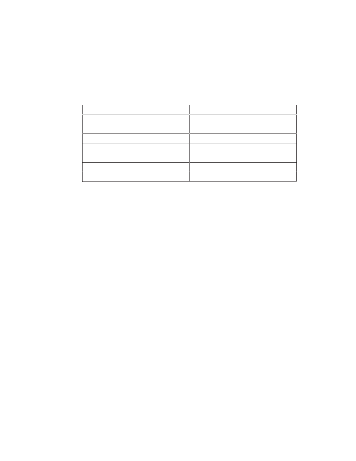
Table 4-1 gives you an overview of the most important performance features of the
FM 456-2 application function module.
Table 4-1 Performance Features of the FM 456-2 application function module
Performance Features
Processor Pentium 120 MHz
Main memory installed 16 Mbytes, 3.3 V EDO RAM
Second-Level Cache 256 Kbytes
Submodule slot for memory card yes
Submodule slot for interface submodules 2
Connection of expansions max. 3
“Watchdog” yes
The FM 456-2 application function module contains a 2 8 MBytes, 3.3 V EDO
DRAM main memory when being delivered.
4.2 Overview of Hardware Elements
This section provides you with information you will need about the individual
elements of an FM 456-2 application function module when carrying out startup
and during operation. You will need this information to be able to respond to
displays, to start up and to use an FM 456-2 and to be able to handle other
components (for example, memory cards, expansion modules).
FM 456-2
4-2
FM 456-2 Application Function Module Installation, Hardware, and Startup
C79000-G7076-C458-01
Page 57
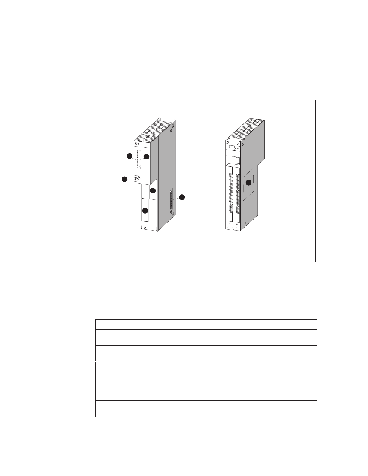
General View
Figure 4-1 shows the front and rear view of the FM 456-2 without covering flap.
The positions of the indicators, operator controls and other elements required for
operation can be seen from this figure.
FM 456-2 Functions and Technical Data
Front elevation Rear elevation
2
1
1 = Slot for memory card
2 = Status and fault indicators
3 = Mode selector switch
Figure 4-1 Front and Rear View of an FM 456-2 Without Covering Flap
FM 456-2 Elements
Table 4-2 Elements of the FM 456-2
Element
Mode selector switch The mode selector on the FM 456-2 is in the form of a key switch
Status and fault
indicators
Module slot for
memory card
Expansion socket M7-400 expansion units can be connected via this expansion
Slots for interface
submodules
3
4
5
4
4 = Slot for interface submodules
5 = Expansion socket
6 = Cover for memory submodule slot
Function
(see Section 4.3).
The status and fault indicators show the operating status of the
FM 456-2 (see Section 4.4).
A full-size S7 memory card can be inserted in the module slot.
During start-up, the system and user software can be loaded into
working memory from this memory card (see Section 4.5).
socket (see Section 4.6).
Interface submodules can be inserted in these slots (see
Section 4.7).
6
8
FM 456-2 Application Function Module Installation, Hardware, and Startup
C79000-G7076-C458-01
4-3
Page 58
FM 456-2 Functions and Technical Data
4.3 Mode Selector
Mode Selector
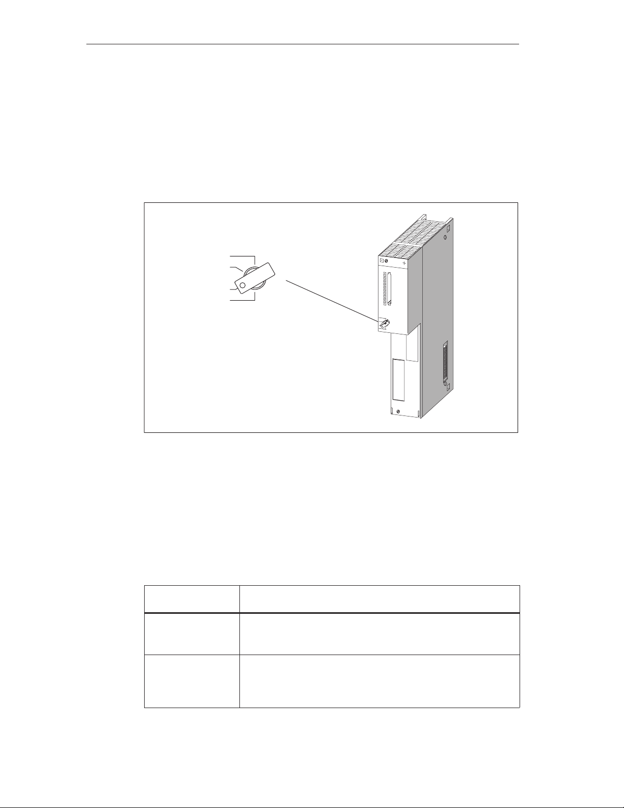
The mode selector on the FM 456-2 is in the form of a key switch.
The following illustration shows the location and positions of the mode selector.
RUN-P
RUN
STOP
MRES
Figure 4-2 FM 456-2 Mode Selector
The settings of the mode selector can be examined by the software. The
significance of the individual switch positions can thus vary depending on the
program.
Mode Selector Positions
Table 4-3 FM 456-2 Mode Selector Positions
Mode Selector
Position
RUN-P The FM 456-2 processes the user program. Write and read access
RUN The FM 456-2 processes the user program. Read access only to
Explanation
to the CPU are possible.
The key cannot be removed when in this position.
the CPU is possible.
The key can be removed in this position to prevent unauthorized
change of mode.
4-4
FM 456-2 Application Function Module Installation, Hardware, and Startup
C79000-G7076-C458-01
Page 59
Table 4-3 FM 456-2 Mode Selector Positions
FM 456-2 Functions and Technical Data
Mode Selector
STOP The user program on the FM 456-2 cannot access the I/O
MRES Spring-return position of the key switch for software-controlled re-
Activating MRES
To effect a hardware reset via MRES, proceed as follows:
1. Turn the mode selector to the STOP position.
Result: The STOP indicator lights up
2. Turn the mode selector to MRES and hold it in this position.
Result: The STOP indicator goes out for 1 second, lights up for 1 second,
goes out for 1 second and then lights up steadily.
3. Turn the mode selector back to the STOP position, to the MRES position again
and back to the STOP position within 3 seconds.
Result: The STOP indicator flashes for at least 3 seconds at 2 Hz (general
reset being carried out) and then lights up again.
Explanation
Position
modules. The user program cannot control the process.
The key can be removed in this position to prevent unauthorized
change of mode.
set of the FM 456-2 (hardware reset).
4. If the STOP indicator does not flash or other indicators light or flash, steps 2
and 3 must be repeated.
Note
The resetting of the module by activating MRES is controlled by the system
software. If this has not been started, the FM 456-2 must be reset, if necessary, by
switching the power on and off. If a keyboard is connected to the FM 456-2, it is
possible to initiate a cold start via the hotkeys CTRL+ALT+HOME.
FM 456-2 Application Function Module Installation, Hardware, and Startup
C79000-G7076-C458-01
4-5
Page 60
FM 456-2 Functions and Technical Data
4.4 Status and Fault Indicators
Status and Fault Indicators
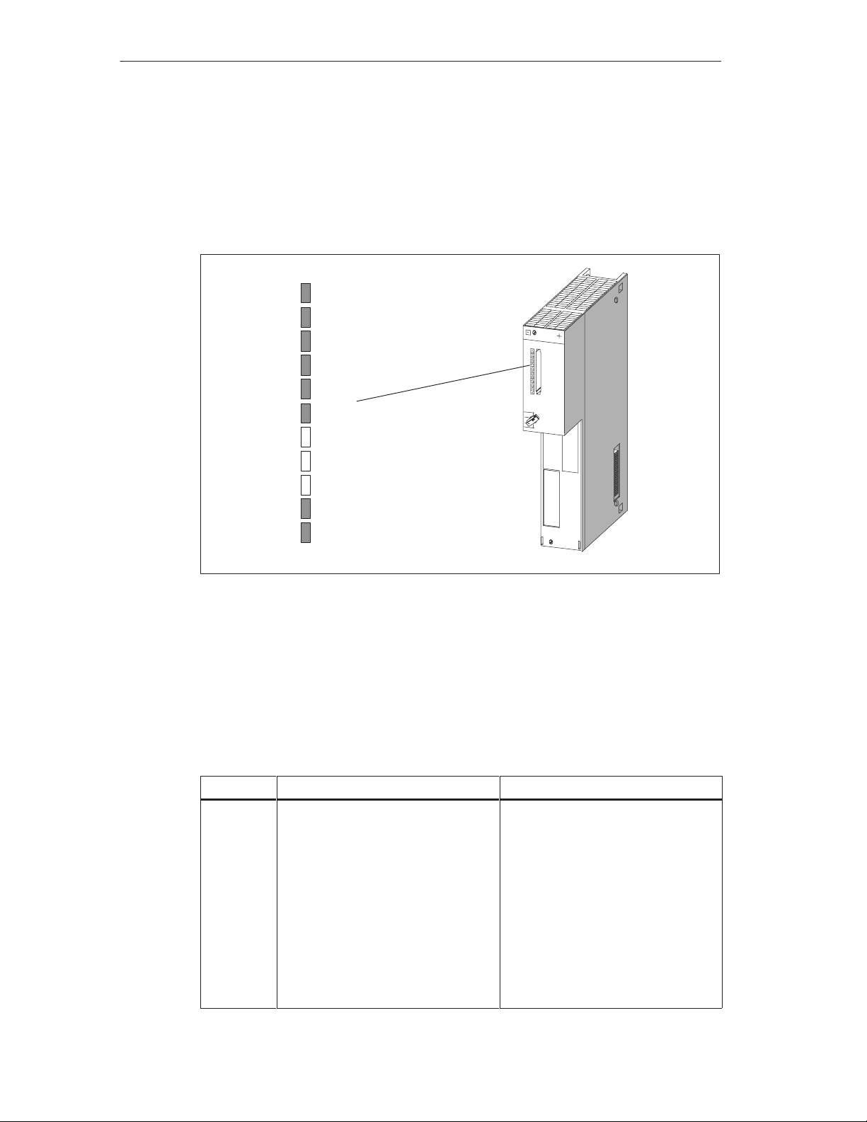
The FM 456-2 is provided with the following status and fault indicators:
INTF
EXTF
SD
HD
USR1
USR2
RUN
STOP
Figure 4-3 Status and Fault Indicators on the FM 456-2
Meaning of Status and Fault Indicators
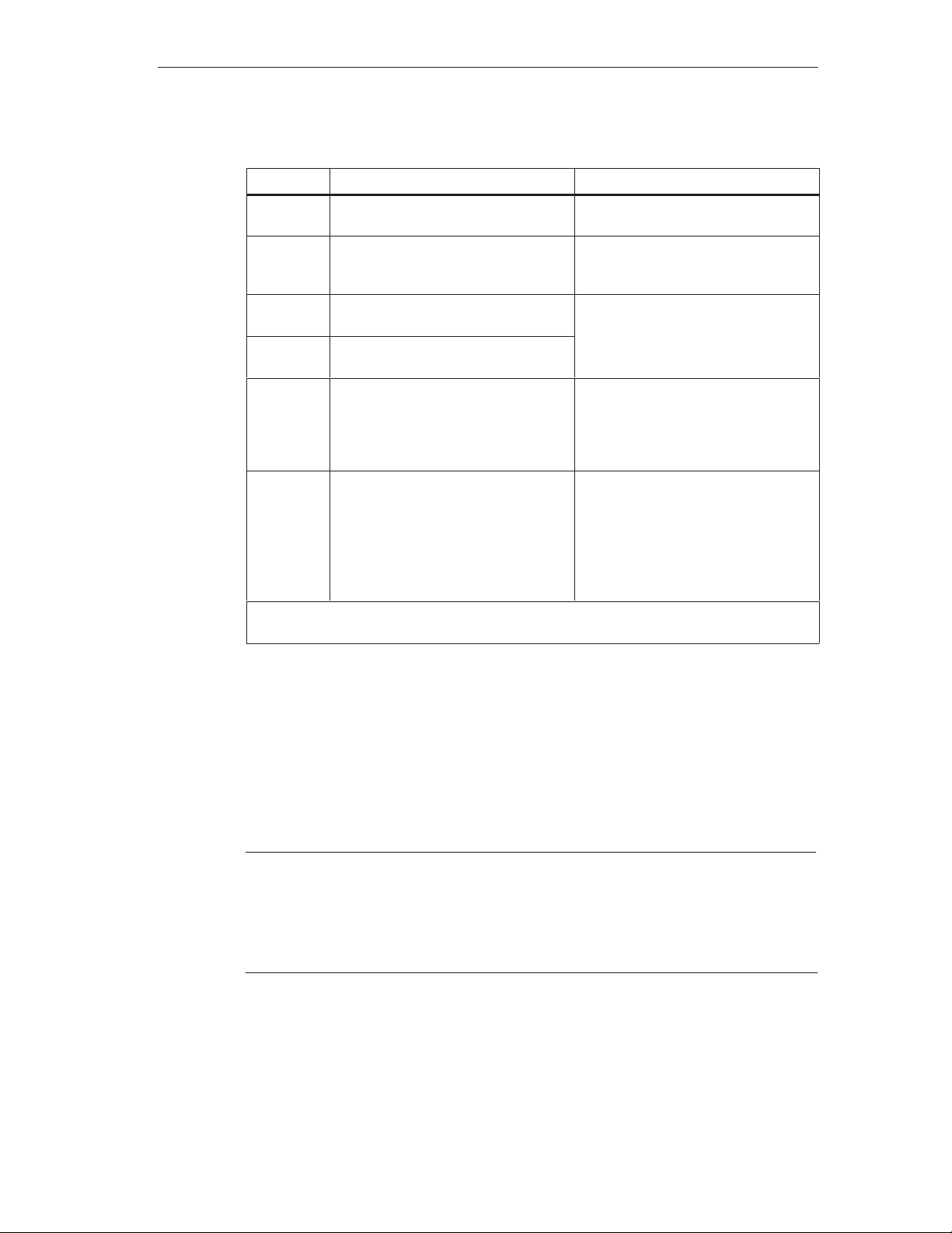
The status and fault indicators are explained in Table 4-4 in the order in which they
are arranged on the FM 456-2 application function module.
Table 4-4 Meaning of the Status and Fault Indicators on the FM 456-2
Indicator
INTF (red)
EXTF (red)
Internal or external alarm lights in the event of
Meaning Description
Hardware faults
Firmware faults
Parameter assignment faults
Computational faults
Timer faults
Memory card faults
I/O faults.
Use the PG to determine the exact
nature of the fault (read diagnosis
buffer).
4-6
FM 456-2 Application Function Module Installation, Hardware, and Startup
C79000-G7076-C458-01
Page 61
FM 456-2 Functions and Technical Data
Table 4-4 Meaning of the Status and Fault Indicators on the FM 456-2
Indicator DescriptionMeaning
SD(green) Access to memory card Lights when read or write access to
the memory card occurs.
HD
(green)
USR1
(yellow)
USR2
(yellow)
RUN
(green)
STOP
(yellow)
Access to hard disk Lights when read or write access to
the hard disk on the mass storage
module occurs.
Special indicator for the user program (user)
Special indicator for the user program (user)
“RUN” status indicator Lights if the system software is
“STOP” status indicator Lights when the user program of
Can be allocated by the user (see
programming manual).
loaded and user programs are running
(write accesses to the I/O are enabled)
the programmable module is not
controlling the process (write
accesses to the I/O are not
enabled)
Flashes when a memory reset is
requested or is being performed.
All indicators light briefly as a self-test following an MRES (see Page 4-5) or switching on
of the power supply .
4.5 Memory Card
The FM 456-2 application function module provides a facility to use memory cards
as data medium or mass storage. This section provides you with information on
how to use this facility.
Note
If a power failure occurs during write access to the memory card, the entire
content of the memory card may be corrupted under worst case conditions.
Please note that, unlike a diskette, the memory card with flash EPROM is only
suitable for a limited number of write operations.
A memory card simulates a diskette drive from which the operating system can be
booted. It can also be used for changing user software and data.
For the FM 456-2, memory cards with flash EPROM are available (see Section 5,
“Ordering Information”).
FM 456-2 Application Function Module Installation, Hardware, and Startup
C79000-G7076-C458-01
4-7
Page 62

FM 456-2 Functions and Technical Data
Drive Assignment and Boot Sequence
The memory card is addressed by the operating system in the same way as a
conventional drive.
The drive assignment and the boot sequence can be set in the BIOS setup (see
chapter on central processing units for M7-400, BIOS setup of the
manual /1/
.
Formatting
Memory cards can be formatted with PG/PC or M7-400. Read the relevant
sections in the
Note
The memory capacity specified for the memory card is the actual physical memory
capacity (gross). Formatting reduces the gross memory capacity to approximately
80% (net) that is then available to the operating system for storing data/programs.
M7-SYS /2/
user manual.
reference
UNDELETE:
Files which were deleted from the memory card cannot be restored using
UNDELETE programs.
4.6 Expansion Socket
The FM 456-2 application function module is provided with an expansion socket,
allowing you to connect up to three M7-400 expansion modules. The ISA bus is
extended via the expansion socket.
Which Expansion Modules Can Be Connected?
One EXM 478 extension module with up to three interface submodules, one
MSM 478 mass storage module with diskette and hard disk drive or one ATM 478
AT adapter module for short AT cards can be connected directly to the FM 456-2
application function module.
A total of up to 3 expansions can be connected in series to the CPU.
If three EXM 478 expansion modules are connected, up to 11 interface modules
can be operated together with the slots on the relevant application function
module.
Assembly Rules
The rules for the sequence of assembly and the possible combinations of
expansion modules can be found in the chapter “M7-400 Expansion Modules” in
manual /1/
4-8
.
FM 456-2 Application Function Module Installation, Hardware, and Startup
C79000-G7076-C458-01
Page 63
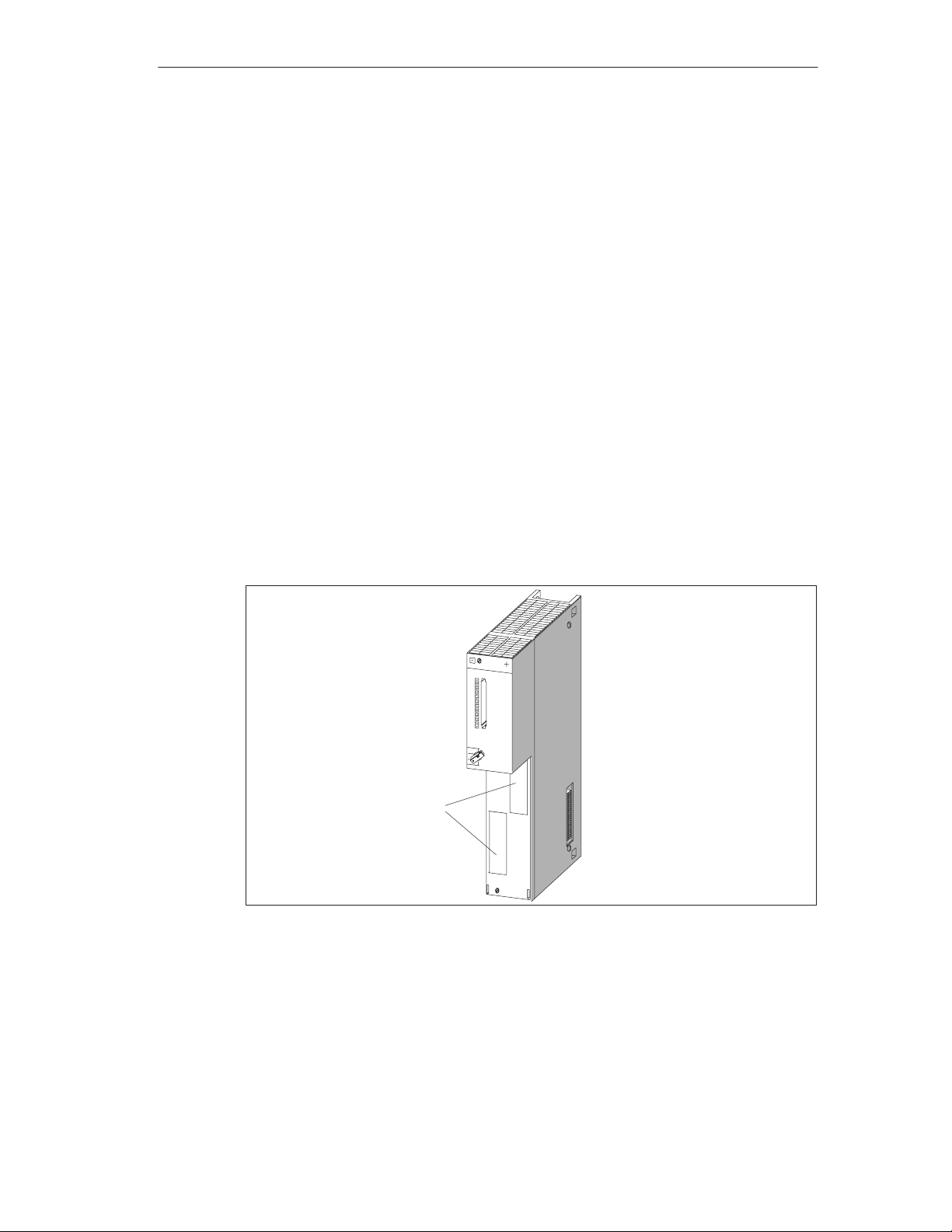
4.7 Slots for Interface Submodules
Definition
The submodule slot is a receptacle for a submodule. The FM 456-2 application
function module has a slot for the memory card and two slots for interface
submodules.
Figure 4-4 shows the position of the two slots for interface submodules on the
FM 456-2 application function module.
Slot Numbering
Each slot for an interface submodule has a submodule slot number assigned to it.
The submodule slot number depends on the module slot and on the arrangement
of the slot on the expansion module or the CPU. You can see the submodule slot
numbers in Figure 4-5.
FM 456-2 Functions and Technical Data
You require these submodule slot numbers for configurations that you undertake in
the BIOS setup or for determining the I/O addresses of an interface module (see
the chapter “Expansions for M7-400” in the
Module slot
Figure 4-4 Position of the Module Slots for Interface Submodules on the FM 456-2
Application Function Module
reference manual /1/
).
Figure 4-5 shows the numbering of the interface submodule slots.
FM 456-2 Application Function Module Installation, Hardware, and Startup
C79000-G7076-C458-01
4-9
Page 64
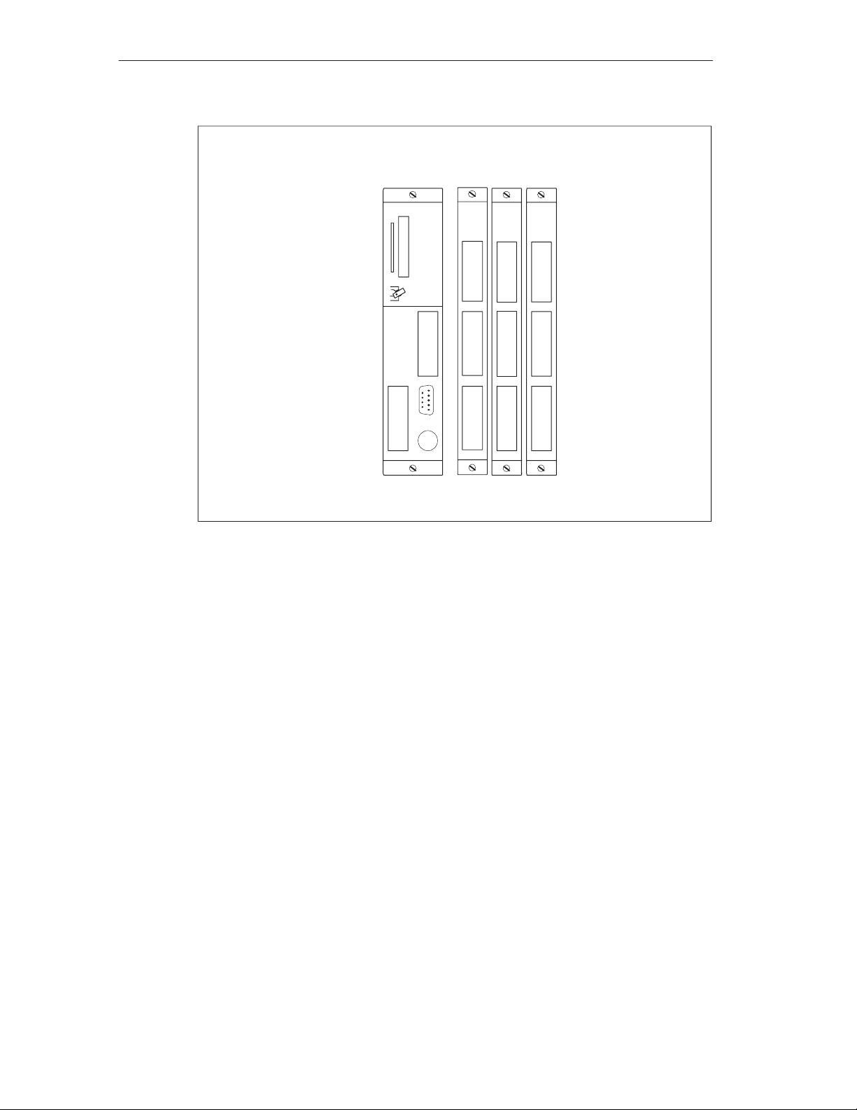
FM 456-2 Functions and Technical Data
FM 456-2
3
08
Slot n n+2 n+3 n+4n+1
Figure 4-5 Submodule Slot Numbers on the FM 456-2 and EXM 478
EXM 478
6
7
10 13
912
11 14
Preferred Slot for IF 964-DP
If the IF 964-DP interface module is inserted in the preferred slot number 3 or if no
IF 964-DP interface module is used, the whole main memory up to 16 Mbytes can
be used.
If the IF 964-DP interface module is inserted in another slot, only up to 15 Mbytes
can be used.
Determining the Basic Address for the Interface Submodule
The method of determining the basic addresses for the interface modules is given
in the chapter “M7-400 Expansion Modules” in
manual /1/
“Addressing the EXM 478 Expansion Modules”.
Module Cover
Unused slots are protected by module covers.
, in the section
4-10
FM 456-2 Application Function Module Installation, Hardware, and Startup
C79000-G7076-C458-01
Page 65

4.8 Watchdog
Method of Operation
The FM 456-2 contains a watchdog for monitoring user programs. This is called on
a cyclic basis by the system software. If the cyclic operation fails (for instance, if
the software “hangs”), the module is reset after the watchdog period has expired.
The cause of the reset is stored and is evaluated by the diagnosis software.
4.9 Buffering
The S7-400 rack is buffered centrally by the back-up battery in the power supply
module.
If central buffering is present, the time and date and the SRAM (256 Kbytes) is
buffered on the FM 456-2 application function module.
FM 456-2 Functions and Technical Data
BIOS Setup
Note
Note that the data content will be lost if the central buffering fails or the module is
unplugged from the rack.
The BIOS setup data, excluding time and date, is stored in the BIOS flash EPROM
and is therefore independent of the central buffering. The BIOS setup is retained if
the central buffering fails or the FM 456-2 is removed from the rack.
FM 456-2 Application Function Module Installation, Hardware, and Startup
C79000-G7076-C458-01
4-11
Page 66

FM 456-2 Functions and Technical Data
4.10 BIOS Setup
The BIOS setup for the FM 456-2 offers the same functions as for the CPU 488-3
and the CPU 486-3. Thus the descriptions in the chapter “CPUs for the M7-400,
the BIOS setup” of the
This sections shows only the BIOS setup windows which differ from those of the
CPUs.
Cold Start
After switch-on or cold starting the application function module, the BIOS (Basic
Input Output System) starts a ”Power On Self Test” (POST) and outputs the
results in the POST window.
Copyright (C) 1984 – 1996 Award Software Intl., Inc.
03/13/96 – Intel–82430HX-3A59I000 01 0000
––––––––––––––––––––––––––––––––––––––––––––––––––––––––––––––––
CPU Type Pentium 120MHz
Math CoProcessor Internal
Base Memory 640 Kb
Extended Memory 15360 Kb
BIOS Shadow RAM Enabled
Video Shadow RAM Enabled
PS2 Mouse Disabled
Floppy Drives 1 Found
Hard Drives IBM–DBOA–2540
Serial Ports 2 Found
Parallel Ports 1 Found
Testing Base Memory 640 Kb
Testing Extended Memory 15360 Kb
––––––––––––––––––––––––––––––––––––––––––––––––––––––––––––––––
Press CTRL–ALT–ESC to enter setup
reference manual /1/
PowerBIOS Version 1.00
Siemens AG FM456-2 M7-BIOS A2.11
are also valid for the FM 456-2.
Warm Start
4-12
The following window appears after a warm start of the FM 456-2 with MS-DOS.
This indicates an accelerated system power up.
PowerBIOS Version 1.00
Copyright (C) 1984 – 1996 Award Software Intl., Inc.
03/13/96 – Intel–82430HX-3A59I000 01 0000
Siemens AG FM456-2 M7-BIOS A2.11
Press CTRL-ALT-ESC to enter setup
FM 456-2 Application Function Module Installation, Hardware, and Startup
C79000-G7076-C458-01
Page 67

FM 456-2 Functions and Technical Data
4.11 Address and Interrupt Assignments
This section contains detailed information in tabular form about I/O address area
mapping, memory and interrupt assignments in the FM 456-2 application function
module.
Memory Assignment
The main memory is assigned as follows in the FM 456-2:
Table 4-5 Main Memory Assignment
Address Content
1 MB to 15 MB
E 8000H to F FFFFH BIOS
E 0000H to E 7FFFH Free (32 K)
D 4000H to D FFFFH Free (48 K)
*)
or to 16 MB User memory area
D 0000H to D 3FFFH Reserved for CP 1401 (16 K)
C F000H to C FFFFH Free (16 K)
C C000H to C EFFFH Memory card, otherwise free (12 K)
C 8000H to C BFFFH Reserved (32 K)
C 0000H to C 7FFFH Shadow VGA BIOS (32 K)
A 0000H to B FFFFH VGA (128 K)
0 0000H to 9 FFFFH 640 K system area
*)
If the interface submodule IF 964-DP is not plugged in the preferred slot (see
page 4-10)
Keeping Memory Areas Free
The memory areas that are not always marked as “free” should be kept free when
using a memory manager.
SRAM Area
The size of the SRAM with battery backup is 256 Kbytes (net for data blocks
244 Kbytes). If the battery is removed and inserted again when there is no power
connected, the SRAM content will be lost. This is indicated by the BAF LED.
FM 456-2 Application Function Module Installation, Hardware, and Startup
C79000-G7076-C458-01
4-13
Page 68
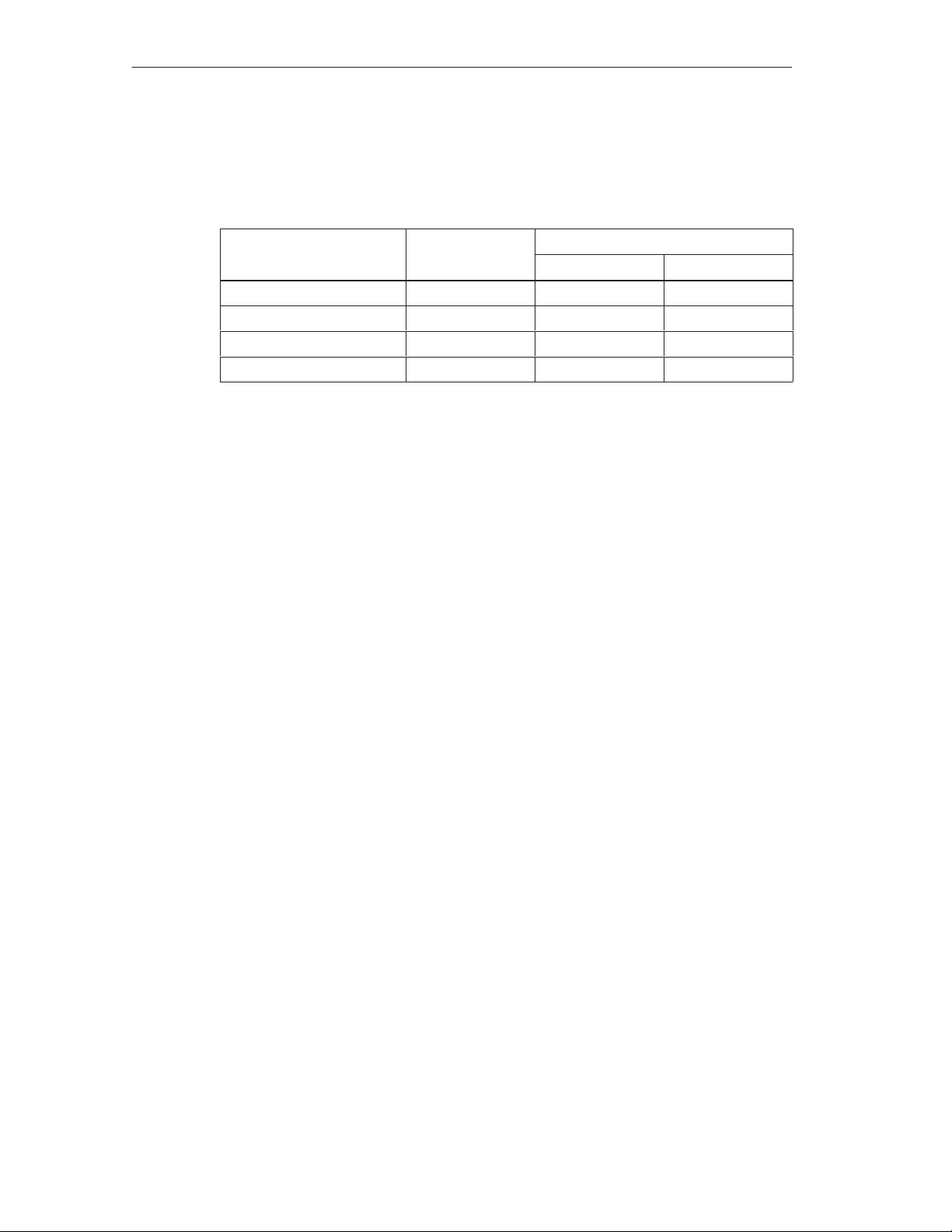
FM 456-2 Functions and Technical Data
Memory Areas for AT Cards
AT cards which are inserted in the expansion module ATM 478 can occupy the
following memory areas:
D 0000H to E 7FFFH 96 K 96 K 32 K
C 8000H to C BFFFH 16 K 16 K 16 K
C C000H to C EFFFH
C F000H to C FFFFH 4 K 4 K 4 K
1)
The area is only available if no memory card is present.
2)
If the driver software under MS-DOS requires expanded memory (EMS), the
memory manager EMM386 occupies 64 K in the area D0000H to E7FFFH
because it must be operated in EMS mode.
I/O Address Area
Addressing of the ISA-compatible input/output components is carried out in the I/O
area at addresses from 0100H to 03FFH. The addresses determined by the ISA
architecture are used. Unlike the original AT, the I/O addresses are fully decoded in
the FM 456-2 module, so that addresses above 03FFH can be used for addressing
M7-400-specific hardware.
Area M7 RMOS32
1)
12 K 12 K 12 K
M7 RMOS32 with MS-DOS
Without EMS With EMS
2)
Address Area for AT Modules
The following address area is available for addressing AT modules in the ATM 478
AT adapter module:
0200H to 03FF
except the area from 03E0H to 03E3H and
except the area occupied by the installed interface submodules (see the
chapter “Interface Submodules” in
4-14
H
reference manual /1/
FM 456-2 Application Function Module Installation, Hardware, and Startup
).
C79000-G7076-C458-01
Page 69

Interrupt Assignment
Table 4-6 Interrupt Assignment
FM 456-2 Functions and Technical Data
Interrupt
NMI Group signal for fault signals
IRQ0 System timer
IRQ1 Reserved for keyboard
IRQ2 Cascading of the 2nd interrupt controller
IRQ3 Reserved for COM2, otherwise free
IRQ4 Reserved for COM1, otherwise free
IRQ5 Reserved for LPT2, otherwise free
IRQ6 Reserved for floppy disk drive, otherwise free
IRQ7 Reserved for LPT1, otherwise free
IRQ8 Real time clock
IRQ9 Software interrupt, diverted to IRQ2
IRQ10
IRQ1 1 Reserved for CP1401 or free
IRQ12 PS2 mouse, otherwise free
IRQ13 Numeric coprocessor
IRQ14 Hard disk
IRQ15 S7 system interrupt
Reserved for IF 964-DP or free
Function
FM 456-2 Application Function Module Installation, Hardware, and Startup
C79000-G7076-C458-01
4-15
Page 70
FM 456-2 Functions and Technical Data
4.12 Technical Data
Features and Technical Data of the FM 456-2
The following table shows the features and technical details of the FM 456-2
application function modules.
Note
The “General technical data” of the S7/M7-400 logic controllers applies (see
reference manual /1/
), unless otherwise specified in this section.
6ES7 456-2AA00-0AB0
ES7 456-2AA00-0AB1 (with MS-DOS)
Features
Processor Pentium 120 MHz
Main memory 16 Mbytes
Buffered memory (SRAM) 256 Kbytes
Second-Level Cache 256 Kbytes
Slots for interface
modules
Option for connection of
expansion modules
2
max. 3
T echnical Data
Supply voltage 5 V DC
Current consumption
(without interface
submodules)
typ.
max. permissible
Power loss
without interface
submodules
2.2 A
2.7 A
max. 13.5 W
max. 16.5 W
with interface
submodules
Forced ventilation
necessary
Dimensions WxHxD (mm) 50 x 290 x 219
Weight 1.3 kg (2.87 lb.)
no
(2” x 11.5” x 8.62”)
4-16
FM 456-2 Application Function Module Installation, Hardware, and Startup
C79000-G7076-C458-01
Page 71
Ordering Information
In this Chapter
Table Subject Page
5-1 M7-400 Application Function Modules 5-1
5-2 M7-400 Expansion Modules 5-2
5-3 M7-400 Interface Submodules 5-2
5-4 Memory Card 5-3
5-5 Connecting Cables 5-3
5-6 Spare Parts and Accessories 5-3
5-7 Documentation 5-4
5.1 M7-400 Application Function Modules
5
Table 5-1 Order Numbers for M7-400 Application Function Modules
Product
FM 456-2 Application function module
(Pentium, 120 MHz, with 16 Mbytes main
memory, 256 Kbytes SRAM)
Description Order Number
6ES7 456-2AA00-0AB0
FM 456-2 Application Function Module Installation, Hardware, and Startup
C79000-G7076-C458-01
5-1
Page 72
Ordering Information
5.2 M7-400 Expansion Modules
Table 5-2 lists all the expansion modules that can be used with the M7-400
application function modules.
Table 5-2 Order Numbers for M7-400 Expansion Modules
Product
ATM 478 A T adapter module (to accept a short AT
module)
EXM 478 Expansion module (to accept 3 interface
submodules)
MSM 478 Mass storage module (3.5” diskette drive
and ≥ 520 Mbytes hard disk and 1 LPT1
parallel interface)
Description Order Number
5.3 M7-400 Interface Submodules
Table 5-3 lists all the interface submodules that can be used with M7-400
application function modules.
Table 5-3 Order Numbers for M7-400 Interface Submodules
Product
IF 961-AIO Analog I/O interface submodule for
analog inputs and outputs
IF 961-CT1 Counter 1 interface submodule
(connection for incremental encoder)
IF 961-DIO Digital I/O interface submodule for
digital inputs and outputs
IF 962-COM COM interface submodule for connecting
up to two serial devices
(for example, mouse, terminal)
IF 962-LPT Interface submodule with parallel interface
(for example, printer)
IF 962-VGA Interface submodule with standard VGA
and keyboard interface
IF 964-DP Interface submodule for connecting
distributed I/Os (via Profibus)
CP 1401 Communications processor
Ethernet (H1) with TCP/IP protocol
Description Order Number
6ES7 478-2CA00-0AC0
6ES7 478-2AC00-0AC0
6ES7 478-2BA00-0AC0
6ES7 961-2AA00-0AC0
6ES7 961-3AA00-0AC0
6ES7 961-1AA00-0AC0
6ES7 962-3AA00-0AC0
6ES7 962-4AA00-0AC0
6ES7 962-1BA01-0AC0
6ES7 964-2AA00-0AB0
6GK1 140-1NA00
5-2
FM 456-2 Application Function Module Installation, Hardware, and Startup
C79000-G7076-C458-01
Page 73
5.4 Memory Card
Table 5-4 lists all the memory cards that can be used with M7-400 application
function modules.
Table 5-4 Order Numbers for Memory Card
Ordering Information
Description
Memory Card, flash-EPROM, 5 V , 4 Mbytes 6ES7 952-1KM00-0AA0
Memory Card, flash-EPROM, 5 V , 8 Mbytes 6ES7 952-1KP00-0AA0
Memory Card, flash-EPROM, 5 V , 16 Mbytes 6ES7 952-1KS00-0AA0
5.5 Connecting Cables
Table 5-5 lists the connecting cables.
Table 5-5 Order Numbers for Connecting Cables
Description
V .24 cables (RS232, ”Null-Modem”), 10 m (33 ft.)
9-pin Sub-D female connectors at both ends
Printer connecting cable for
S Serial interface (COM, 10 m (33 ft.))
S Parallel interface (Centronics)
Order Number
Order Number
9AB4 173-2BN10-0CA0
9AB4 173-2BN10-0CA0
9API 901-0AL00
5.6 Spare Parts and Accessories
Table 5-6 lists spare parts and accessories.
Table 5-6 Order Numbers for Spare Parts and Accessories
Description
Key for FM 456 (mode switch) 6ES7 911-0AA00-0AA0
12 module covers 6ES7 398-0BA00-0AA0
6 connecting clips 6ES7 498-6BA00-0AA0
FM 456-2 Application Function Module Installation, Hardware, and Startup
C79000-G7076-C458-01
Order Number
5-3
Page 74

Ordering Information
5.7 Documentation
Table 5-7 lists all the documentation that can be ordered in addition to this manual.
Table 5-7 Order Numbers for Documentation
Description
FM 456 Application Function Module
Installation, Hardware, and Startup
Manual
S7-400, M7-400 Programmable Controllers
Installation and Hardware
Manual
S7-400, M7-400 Programmable Controllers
Module Specifications
Reference Manual
System Software for M7-300/400
Program Design
Programming Manual
System Software for M7-300/400
System and Standard Functions
Reference Manual
System Software for M7-300/400
Installation and Operation
User Manual
ProC/C++ for M7-300/400
Writing C Programs
User Manual
ProC/C++ for M7-300/400
Debugging C Programs
User Manual
CFC for S7 and M7
Graphical Interconnection of Technological
Functions
Manual
Langugage Order Number
English
French
German
English
French
German
English
German
English
German
English
French
6ES7456-2AA00-8BA0
6ES7456-2AA00-8CA0
6ES7498-8AA02-8AA0
6ES7498-8AA02-8BA0
6ES7498-8AA02-8CA0
6ES7802-0FA14-8AA0
6ES7802-0FA14-8BA0
6ES7812-0CA01-8AA0
6ES7812-0CA01-8BA0
6ES7813-0CA02-8AA0
6ES7813-0CA02-8BA0
6ES7813-0CA02-8CA0
5-4
FM 456-2 Application Function Module Installation, Hardware, and Startup
C79000-G7076-C458-01
Page 75

Bibliography
For programming and startup of the M7-400 application function modules you will
need the following manuals in addition:
No. Manual Content Order Number
/1/
S7-400, M7-400 Programmable
Controllers
Installation and Hardware Manual
Module Specifications, Reference
Manual
/2/
M7-SYS, System Software for M7-300/400
Program Design
System and Standard Functions
Installation and Operation
/3/
STEP 7
Programming with STEP 7
Configuring Hardware with STEP 7
Configuration, installation
and preparation for
startup
Writing C Programs for
M7 CPU/FM modules
with the M7-SYS RT.
programming package.
Operating STEP 7,
Configuring hardware
with STEP 7
6ES7498-8AA02-8AA0
6ES7802-0FA14-8AA0
included in STEP 7
documentation package
A
FM 456-2 Application Function Module Installation, Hardware, and Startup
C79000-G7076-C458-01
A-1
Page 76

Bibliography
A-2
FM 456-2 Application Function Module Installation, Hardware, and Startup
C79000-G7076-C458-01
Page 77
Rules for Handling Electrostatically
Sensitive Devices (ESD)
Introduction
This appendix explains
What lies behind the term “electrostatically sensitive devices”
What precautions must be observed when handling electrostatically sensitive
modules.
Contents
You will find the following information about electrostatically sensitive modules in
this appendix:
Section Subject Page
B.1 What Does ESD Mean? B-2
B.2 Electrostatic Charging of Persons B-3
B.3 Basic Precautions Against Electrostatic Discharges B-4
B
FM 456-2 Application Function Module Installation, Hardware, and Startup
C79000-G7076-C458-01
B-1
Page 78

Rules for Handling Electrostatically Sensitive Devices (ESD)
B.1 What Does ESD Mean?
Definition
All electronic modules are equipped with highly integrated devices or components.
Because of their technology, these components are very sensitive to overvoltages
and therefore to static electrical discharges.
The abbreviation ESD is used internationally for these Electrostatically Sensitive
Devices. In Germany these are referred to as EGB (Elektrostatisch Gefährdeten
Baugruppen).
Electrostatically sensitive devices are identified with the symbol shown below:
Caution
!
Electrostatically sensitive devices can be destroyed by voltages well below those
that you can normally detect. These voltages occur when you touch a component
or the connections of a module without having first ensured that you are
electrostatically discharged. The damage that can be caused to a module by
overvoltage cannot usually be recognized immediately, but only becomes apparent
after a lengthy period of operation.
B-2
FM 456-2 Application Function Module Installation, Hardware, and Startup
C79000-G7076-C458-01
Page 79
Rules for Handling Electrostatically Sensitive Devices (ESD)
B.2 Electrostatic Charging of Persons
Charging
Any person whose electrical potential is not equalized to that in their environment
can become electrostatically charged.
Figure B-1 shows the maximum electrostatic voltage with which a person can
become charged when coming into contact with the materials shown. These values
correspond to the figures in IEC 801-2.
Voltage in kV
(kV)
16
15
14
13
12
11
10
9
8
7
6
5
4
3
2
1
3
1
2
1 Synthetic material
Wool
2
Antistatic material such as
3
wood or concrete
510
20 30 40 50 60 70 80 90 100
Figure B-1 Electrostatic V oltages with which a Person May Become Charged
FM 456-2 Application Function Module Installation, Hardware, and Startup
C79000-G7076-C458-01
Relative
humidity in %
B-3
Page 80

Rules for Handling Electrostatically Sensitive Devices (ESD)
B.3 Basic Precautions Against Electrostatic Discharge
Ensure a Good Ground
When handling electrostatically sensitive modules, ensure that persons, workplace
and packaging are effectively earthed. This will avoid static charging.
Avoid Touching Components Directly
Only touch electrostatically sensitive components if this is unavoidable (for
example during maintenance work). Hold the module so that you do not touch
either the module pins or the printed circuit tracks. In this way, the electrical
discharge energy will not be able to reach sensitive components and cause
damage.
If you have to take measurements on a module, first discharge any static about
your body before carrying out the work. This can be done by touching a grounded
metallic object. Use only grounded measuring instruments.
B-4
FM 456-2 Application Function Module Installation, Hardware, and Startup
C79000-G7076-C458-01
Page 81

Index
A
Address and interrupt assignments, FM 456-2,
4-13
AT card, installing, 2-6
ATM 478, installing the AT card, 2-6
B
BIOS, M7-400, warm start, 4-12
Buffering, FM 456-2, 4-11
C
Cable lengths, 2-23
Checklist, M7-400, preparing for operation,
2-20
Commissioning
checklist, 2-2
first switch-on, 2-26
Configuration, example, 1-3
Connecting
operator panels and peripherals, 2-21
PC, 2-23
printer, 2-22
programming unit, 2-23
Connecting a mouse, M7-400, 2-23
Connecting, M7-400, module assembly, 2-19
Connection, keyboard, 2-21
E
Expansion connector, removing the cover, 2-9
Expansion modules
covers for unused card slots, 2-5
interconnecting, 2-12
Expansion socket, removing the cover, 2-9
F
Fault indicators, FM 456-2, 4-6
First switch-on, 2-26
FM 456-2
address and interrupt assignments, 4-13
BIOS setup, 4-12
buffering, 4-11
expansion socket, 4-8
fault indicators, 4-6
interface modules, 4-9
interrupt assignment, 4-15
introduction, 4-2
LED indicators, 4-6
memory card, 4-7
mode selector, 4-4
MRES, 4-5
overview, 1-2
performance features, 4-2
reset, 4-5
setup, 4-12
status and fault indicators, 4-6
technical data, 4-16
time monitoring, 4-11
watchdog, 4-11
Formatting, memory card, 4-8
I
IF submodule, installing, 2-4
Installing, in module rack, 2-14
Interface modules, FM 456-2, 4-9
Interface submodule, installing, 2-4
Internet, vii
Introduction, FM 456-2, 4-2
FM 456-2 Application Function Module Installation, Hardware, and Startup
C79000-G7076-C458-01
Index-1
Page 82

Index
K
Keyboard, 2-21
L
LED indicators, FM 456-2, 4-6
M
M7-400, memory assignment, 4-13
M7-400, components, 1-4
Memory assignment, M7-400, 4-13
Memory card
FM 456-2, 4-7
inserting/removing, 2-18
Module assembly, M7-400, connecting, 2-19
Module replacement
application function module, 3-4
AT module, 3-9
expansion module, 3-4
interface submodule, 3-2
Modules
clipping together, 2-13
interconnecting, 2-12
P
Performance features, FM 456-2, 4-2
Plug, removing the cover, 2-9
Preparing for operation, M7-400, 2-20
checklist, 2-20
Printer, 2-22
PROFIBUS-DP , 2-20
S
Setup, 4-12
Socket, removing the cover, 2-9
Startup, Sections, 2-1
Startup, M7-400, steps, 2-21
Status and fault indicators, FM 456-2, 4-6
System software, 1-5
T
Technical data, FM 456-2, 4-16
W
Warm start, M7-400, 4-12
Index-2
FM 456-2 Application Function Module Installation, Hardware, and Startup
C79000-G7076-C458-01
Page 83

Siemens AG
A&D AS E 81
Oestliche Rheinbrueckenstr . 50
D-76181 Karlsruhe
Federal Republic of Germany
From:
Your Name: _____________________________
Your Title: _____________________________
Company Name: __________________________
Street: __________________________
City, Zip Code__________________________
Country: __________________________
Phone: __________________________
Please check any industry that applies to you:
r Automotive
r Chemical
r Electrical Machinery
r Food
r Instrument and Control
r Nonelectrical Machinery
r Petrochemical
r Pharmaceutical
r Plastic
r Pulp and Paper
r Textiles
r Transportation
r Other ___________
FM 456-2 Application Function Module Installation, Hardware, and Startup
6ES7456-2AA00-8BA0-01
$
1
Page 84

Remarks Form
Y our comments and recommendations will help us to improve the quality and usefulness
of our publications. Please take the first available opportunity to fill out this questionnaire
and return it to Siemens.
Please give each of the following questions your own personal mark within the range
from 1 (very good) to 5 (poor).
1. Do the contents meet your requirements?
2. Is the information you need easy to find?
3. Is the text easy to understand?
4. Does the level of technical detail meet your requirements?
5. Please rate the quality of the graphics/tables:
Additional comments:
___________________________________
___________________________________
___________________________________
___________________________________
___________________________________
___________________________________
___________________________________
___________________________________
___________________________________
___________________________________
___________________________________
___________________________________
2
FM 456-2 Application Function Module Installation, Hardware, and Startup
6ES7456-2AA00-8BA0-01
 Loading...