

Siemens SIMATIC FM 453 User Manual

Preface, Contents
Part 1: User Information
SIMATIC
FM 453 Servo Drive /
Step Drive Positioning Module
Manual
Product Summary
Basic Principles of Positioning
Installing and Removing the
FM 453
Wiring the FM 453
Defining Parameters of the
FM 453
Programming the FM 453
Starting up the FM 453
Human-Machine Interface
for the OP 17
1
2
3
4
5
6
7
8
This manual is a component part of the
FM 453 configuration package with the order number
6ES7 453-3AH00-7EG0
Part 2: Reference Information
Description of Functions
Writing Traversing Programs
Troubleshooting
Appendices
Technical Specifications
Connecting Cables
List of Abbreviations
Index
9
10
11
A
B
C
C79000-G7076-C453-01

Safety guidelines
!
!
!
This manual contains notices intended to ensure personal safety, as well as to protect the products and connected equipment against damage. These notices are highlighted by the symbols shown below and graded according to severity by the following texts:
Danger
indicates that death, severe personal injury or substantial property damage will result if proper
precautions are not taken.
Warning
indicates that death, severe personal injury or substantial property damage can result if proper
precautions are not taken.
Caution
indicates that minor personal injury or property damage can result if proper precautions are not
taken.
Note
draws your attention to particularly important information on the product, handling the product,
or to a particular part of the documentation.
Qualified Personnel
Correct Usage
!
Trademarks
The reproduction, transmission or use of this document or its
contents is not permitted without express written authority.
Offenders will be liable for damages. All rights, including rights
created by patent grant or registration of a utility model or design, are
reserved.
Siemens AG
Bereich Automatisierungstechnik
Industrial Automation Systems
Postfach 4848, D-90327 Nürnberg
The device/system may only be set up and operated in conjunction with this manual.
Only qualified personnel should be allowed to install and work on this equipment. Quali-
fied persons are defined as persons who are authorized to commission, to ground, and to tag
circuits, equipment, and systems in accordance with established safety practices and standards.
Note the following:
Warning
This device and its components may only be used for the applications described in the catalog
or the technical description, and only in connection with devices or components from other
manufacturers which have been approved or recommended by Siemens.
This product can only function correctly and safely if it is transported, stored, set up, and
installed correctly, and operated and maintained as recommended.
SIMATICR and SINECR are registered trademarks of SIEMENS AG.
Third parties using for their own purposes any other names in this document which refer to
trademarks might infringe upon the rights of the trademark owners.
Disclaimer of LiabilityCopyright E Siemens AG 1997 All rights reserved
We have checked the contents of this manual for agreement with the
hardware and software described. Since deviations cannot be precluded entirely, we cannot guarantee full agreement. However , the
data in this manual are reviewed regularly and any necessary corrections included in subsequent editions. Suggestions for improvement are welcomed.
Technical data subject to change.
E Siemens AG 1997
Siemens Aktiengesellschaft C79000-G7076-C453

Preface
Purpose of this
Document
Information Blocks
in this Manual
This manual contains all information about the FM 453 module:
S Hardware and functions
S Parameter definition
S Man-machine interface
S S7 function blocks
S Safe setup
The following information blocks describe the purpose and uses of this
manual:
S Product overview of the module (Chapter 1)
This section explains the purpose and possible applications of the module.
It provides introductory information about the FM 453 and its functions.
S Basic principles of positioning (Chapter 2)
Here you will find introductory information on positioning methods and
associated definitions of terms.
S Installing and removing the FM 453 (Chapter 3)
Explains the installation and removal of the FM 453.
S Wiring the FM 453 (Chapter 4)
Describes the connection and wiring of drives, encoders and digital input/
output modules.
S Defining parameters of the FM 453 (Chapter 5)
Describes the parameterization and functions of “Parameterize FM 453.”
S Programming the FM 453 (Chapter 6)
Describes how to program the FM 453 with STEP 7.
S Starting up the FM 453 (Chapter 7)
Describes startup procedures for the FM 453.
S Human-machine interface (Chapter 8)
Describes the various options for operating and monitoring the FM 453,
and which data and signals can be used and monitored.
FM 453 Servo Drive / Step Drive Positioning Module
C79000-G7076-C453-01
iii

Preface
S Reference information and appendices for finding factual information
(module functions, programming guide, interface signals, error handling,
technical specifications, standard HMI user interface)
S List of abbreviations and index for looking up information.
User Requirements
FM 453 Users
The present manual describes the hardware and functions of the FM 453.
T o set up, program and start up a SIMATIC S7-400 with the FM 453, you
will need a knowledge of:
S The SIMATIC S7
S7-400/M7-400 Programmable Controllers, Hardware and Installation
manual
S Your programming device (PG)
S How to perform programming with STEP 7
S How to configure an operator panel interface.
The structure and presentation of the information in the manual are oriented
to the intended uses of the FM 453, and the user’s own activity.
It distinguishes among the following:
S Installation
These activities include installation and wiring of the FM 453.
S Programming
These activities include parameterizing and programming the FM 453.
S Troubleshooting and diagnostics
These activities include detecting and correcting faults and errors
– in the hardware setup of the module and its components
– and in the programming, handling and control of module functions.
S Operation
These users operate the FM 453. The operator accordingly deals only with
the control of positioning tasks.
iv
FM 453 Servo Drive / Step Drive Positioning Module
C79000-G7076-C453-01

Preface
CE Marking
Additional
Assistance
Hotline
Our products are in compliance with the EC Guideline 89/336/EEC “Electromagnetic Compatibility” and the harmonized European standards (EN) which
it embodies.
The EC Declarations of Conformity are held at the address below, where they
can be obtained if and when required by the respective authorities in accordance with Article 10 of the EC Guideline referenced above:
SIEMENS Aktiengesellschaft
Bereich Automatisierungstechnik
AUT E 148
Postfach 1963
D–92209 Amberg
Federal Republic of Germany
If you should encounter any problems using this manual, or if you have any
questions, please contact the office specified on the query form at the end of
this manual.
If you have an urgent problem, please contact:
T est Hotline, +49 911 / 895 – 7000
FM 453 Servo Drive / Step Drive Positioning Module
C79000-G7076-C453-01
v

Preface
vi
FM 453 Servo Drive / Step Drive Positioning Module
C79000-G7076-C453-01

Table of Contents
1 Product Summary 1-1. . . . . . . . . . . . . . . . . . . . . . . . . . . . . . . . . . . . . . . . . . . . . . . . . . . . . . .
1.1 The FM 453 in the S7-400 Programmable Controller 1-2. . . . . . . . . . . . . . . . . .
1.2 Module Description 1-6. . . . . . . . . . . . . . . . . . . . . . . . . . . . . . . . . . . . . . . . . . . . . . .
1.3 Overview of Module Functions for Each Channel 1-9. . . . . . . . . . . . . . . . . . . . .
2 Basic Principles of Positioning 2-1. . . . . . . . . . . . . . . . . . . . . . . . . . . . . . . . . . . . . . . . . . .
3 Installing and Removing the FM 453 3-1. . . . . . . . . . . . . . . . . . . . . . . . . . . . . . . . . . . . . .
3.1 Installing the FM 453 3-2. . . . . . . . . . . . . . . . . . . . . . . . . . . . . . . . . . . . . . . . . . . . .
3.2 Removing the FM 453 3-3. . . . . . . . . . . . . . . . . . . . . . . . . . . . . . . . . . . . . . . . . . . .
3.3 Module Replacement 3-3. . . . . . . . . . . . . . . . . . . . . . . . . . . . . . . . . . . . . . . . . . . . .
4 Wiring the FM 453 4-1. . . . . . . . . . . . . . . . . . . . . . . . . . . . . . . . . . . . . . . . . . . . . . . . . . . . . . .
4.1 Wiring Diagram for a FM 453 4-2. . . . . . . . . . . . . . . . . . . . . . . . . . . . . . . . . . . . . .
4.2 Description of the Drive Interface 4-5. . . . . . . . . . . . . . . . . . . . . . . . . . . . . . . . . . .
4.3 Connecting the Drive Unit 4-12. . . . . . . . . . . . . . . . . . . . . . . . . . . . . . . . . . . . . . . . .
4.4 Description of the Measuring System Interface 4-16. . . . . . . . . . . . . . . . . . . . . . .
4.5 Connecting the Encoders 4-19. . . . . . . . . . . . . . . . . . . . . . . . . . . . . . . . . . . . . . . . .
4.6 Description of the I/O Port 4-21. . . . . . . . . . . . . . . . . . . . . . . . . . . . . . . . . . . . . . . . .
4.7 Wiring Up the Front Connector 4-28. . . . . . . . . . . . . . . . . . . . . . . . . . . . . . . . . . . . .
5 Defining Parameters of the FM 453 5-1. . . . . . . . . . . . . . . . . . . . . . . . . . . . . . . . . . . . . . .
5.1 Installation of “Parameterize FM 453” 5-2. . . . . . . . . . . . . . . . . . . . . . . . . . . . . . .
5.2 Getting Started with “Parameterize FM 453” 5-3. . . . . . . . . . . . . . . . . . . . . . . . .
5.3 Parameter Data 5-6. . . . . . . . . . . . . . . . . . . . . . . . . . . . . . . . . . . . . . . . . . . . . . . . . .
5.3.1 Machine Data 5-10. . . . . . . . . . . . . . . . . . . . . . . . . . . . . . . . . . . . . . . . . . . . . . . . . . .
5.3.2 Increments 5-21. . . . . . . . . . . . . . . . . . . . . . . . . . . . . . . . . . . . . . . . . . . . . . . . . . . . . .
5.3.3 Tool Offset Data 5-22. . . . . . . . . . . . . . . . . . . . . . . . . . . . . . . . . . . . . . . . . . . . . . . . .
5.3.4 Traversing Programs 5-24. . . . . . . . . . . . . . . . . . . . . . . . . . . . . . . . . . . . . . . . . . . . .
5.4 Parameterization with “Parameterize FM 453” 5-26. . . . . . . . . . . . . . . . . . . . . . .
5.5 Storing the Parameter Data in SDB w 1 000 5-31. . . . . . . . . . . . . . . . . . . . . . . . .
6 Programming the FM 453 6-1. . . . . . . . . . . . . . . . . . . . . . . . . . . . . . . . . . . . . . . . . . . . . . . .
6.1 FC INIT_DB (FC 1) – Initialize user DB 6-4. . . . . . . . . . . . . . . . . . . . . . . . . . . . .
6.2 FC MODE_WR (FC 2) – Control Operating Modes and
Process Write Jobs 6-6. . . . . . . . . . . . . . . . . . . . . . . . . . . . . . . . . . . . . . . . . . . . . . .
6.2.1 Process Write Jobs 6-8. . . . . . . . . . . . . . . . . . . . . . . . . . . . . . . . . . . . . . . . . . . . . . .
6.2.2 Control Modes 6-11. . . . . . . . . . . . . . . . . . . . . . . . . . . . . . . . . . . . . . . . . . . . . . . . . . .
FM 453 Servo Drive / Step Drive Positioning Module
C79000-G7076-C453-01
vii

Table of Contents
6.3 FC RD_COM (FC 3) – Process Read Jobs Cyclically 6-13. . . . . . . . . . . . . . . . .
6.4 Reading Diagnostic Information 6-17. . . . . . . . . . . . . . . . . . . . . . . . . . . . . . . . . . . .
6.4.1 FC DIAG_RD (FC 4) – Read Diagnostic Interrupt Data in OB 82 6-17. . . . . .
6.4.2 FC DIAG_INF (FC 6) – Read Diagnostic Interrupt Data in OB 1 6-21. . . . . . . .
6.5 FC MSRMENT (FC 5) – Read Measured Values 6-23. . . . . . . . . . . . . . . . . . . . .
6.6 User Data Block 6-25. . . . . . . . . . . . . . . . . . . . . . . . . . . . . . . . . . . . . . . . . . . . . . . . .
6.7 Example Applications 6-40. . . . . . . . . . . . . . . . . . . . . . . . . . . . . . . . . . . . . . . . . . . . .
6.8 Technical Specifications 6-45. . . . . . . . . . . . . . . . . . . . . . . . . . . . . . . . . . . . . . . . . . .
7 Starting up the FM 453 7-1. . . . . . . . . . . . . . . . . . . . . . . . . . . . . . . . . . . . . . . . . . . . . . . . . . .
7.1 Installation and Wiring 7-2. . . . . . . . . . . . . . . . . . . . . . . . . . . . . . . . . . . . . . . . . . . .
7.2 Initial Values for Testing and Optimization 7-3. . . . . . . . . . . . . . . . . . . . . . . . . . .
7.3 Testing and Optimization 7-8. . . . . . . . . . . . . . . . . . . . . . . . . . . . . . . . . . . . . . . . . .
7.3.1 Activation of the Machine Data 7-13. . . . . . . . . . . . . . . . . . . . . . . . . . . . . . . . . . . . .
7.3.2 Evaluating the Characteristics of the Stepper Motor 7-14. . . . . . . . . . . . . . . . . .
7.3.3 Basic Startup of Stepper Motor Actuation 7-18. . . . . . . . . . . . . . . . . . . . . . . . . . .
7.3.4 Basic Startup of Servomotor Actuation 7-20. . . . . . . . . . . . . . . . . . . . . . . . . . . . . .
7.3.5 Checking the Encoder Actuation 7-23. . . . . . . . . . . . . . . . . . . . . . . . . . . . . . . . . . .
7.3.6 Startup of the Position Controller 7-24. . . . . . . . . . . . . . . . . . . . . . . . . . . . . . . . . . .
7.3.7 Optimizing the Position Control 7-28. . . . . . . . . . . . . . . . . . . . . . . . . . . . . . . . . . . .
7.3.8 Startup of Stepper Motor Control 7-34. . . . . . . . . . . . . . . . . . . . . . . . . . . . . . . . . . .
7.3.9 Realigning the Reference Point Coordinates 7-37. . . . . . . . . . . . . . . . . . . . . . . . .
7.3.10 Activating Position Controller Diagnostics 7-38. . . . . . . . . . . . . . . . . . . . . . . . . . .
7.3.11 Activating Stepper Motor Diagnostics 7-40. . . . . . . . . . . . . . . . . . . . . . . . . . . . . . .
7.3.12 Activation of Software Limit Switches 7-41. . . . . . . . . . . . . . . . . . . . . . . . . . . . . . .
7.3.13 Activation of Drift Compensation 7-41. . . . . . . . . . . . . . . . . . . . . . . . . . . . . . . . . . .
7.3.14 Activation of Backlash Compensation 7-41. . . . . . . . . . . . . . . . . . . . . . . . . . . . . . .
8 Man-Machine Interface 8-1. . . . . . . . . . . . . . . . . . . . . . . . . . . . . . . . . . . . . . . . . . . . . . . . . . .
8.1 Standard HMI (Human-Machine Interface) for the OP 17 8-3. . . . . . . . . . . . . .
8.2 Analysis of the User DB by the User Program for Operator Control 8-7. . . . .
8.3 Data Block for Status Messages (DB-SS) 8-11. . . . . . . . . . . . . . . . . . . . . . . . . . .
9 Description of Functions 9-1. . . . . . . . . . . . . . . . . . . . . . . . . . . . . . . . . . . . . . . . . . . . . . . . .
9.1 Control and Checkback signals 9-2. . . . . . . . . . . . . . . . . . . . . . . . . . . . . . . . . . . .
9.1.1 Control Signals 9-3. . . . . . . . . . . . . . . . . . . . . . . . . . . . . . . . . . . . . . . . . . . . . . . . . .
9.1.2 Checkback Signals 9-6. . . . . . . . . . . . . . . . . . . . . . . . . . . . . . . . . . . . . . . . . . . . . . .
9.1.3 General Handling Information 9-9. . . . . . . . . . . . . . . . . . . . . . . . . . . . . . . . . . . . . .
9.2 Operating Modes 9-12. . . . . . . . . . . . . . . . . . . . . . . . . . . . . . . . . . . . . . . . . . . . . . . .
9.2.1 Jogging 9-13. . . . . . . . . . . . . . . . . . . . . . . . . . . . . . . . . . . . . . . . . . . . . . . . . . . . . . . . .
9.2.2 Open-loop Control 9-16. . . . . . . . . . . . . . . . . . . . . . . . . . . . . . . . . . . . . . . . . . . . . . .
9.2.3 Reference Point Approach 9-17. . . . . . . . . . . . . . . . . . . . . . . . . . . . . . . . . . . . . . . .
9.2.4 Incremental Relative 9-22. . . . . . . . . . . . . . . . . . . . . . . . . . . . . . . . . . . . . . . . . . . . . .
9.2.5 MDI (Manual Data Input) 9-25. . . . . . . . . . . . . . . . . . . . . . . . . . . . . . . . . . . . . . . . . .
9.2.6 Automatic 9-29. . . . . . . . . . . . . . . . . . . . . . . . . . . . . . . . . . . . . . . . . . . . . . . . . . . . . . .
9.2.7 Automatic Single Block 9-34. . . . . . . . . . . . . . . . . . . . . . . . . . . . . . . . . . . . . . . . . . .
9.3 System Data 9-35. . . . . . . . . . . . . . . . . . . . . . . . . . . . . . . . . . . . . . . . . . . . . . . . . . . .
9.3.1 Change Parameters/Data (Job No. 8) 9-36. . . . . . . . . . . . . . . . . . . . . . . . . . . . . . .
viii
FM 453 Servo Drive / Step Drive Positioning Module
C79000-G7076-C453-01

Table of Contents
9.3.2 Single Functions (Job No. 10) 9-39. . . . . . . . . . . . . . . . . . . . . . . . . . . . . . . . . . . . .
9.3.3 Single Commands (Job No. 11) 9-42. . . . . . . . . . . . . . . . . . . . . . . . . . . . . . . . . . . .
9.3.4 Zero Offset (Job No. 12) 9-44. . . . . . . . . . . . . . . . . . . . . . . . . . . . . . . . . . . . . . . . . .
9.3.5 Set Actual Value (Job No. 13) 9-46. . . . . . . . . . . . . . . . . . . . . . . . . . . . . . . . . . . . . .
9.3.6 Set Actual Value On the Fly (Job No. 14) 9-47. . . . . . . . . . . . . . . . . . . . . . . . . . . .
9.3.7 Request Application Data (Job No. 18) 9-48. . . . . . . . . . . . . . . . . . . . . . . . . . . . . .
9.3.8 Teach In (Job No. 19) 9-49. . . . . . . . . . . . . . . . . . . . . . . . . . . . . . . . . . . . . . . . . . . . .
9.3.9 Set Reference Point (Job No. 21) 9-49. . . . . . . . . . . . . . . . . . . . . . . . . . . . . . . . . .
9.3.10 Measured Values 9-50. . . . . . . . . . . . . . . . . . . . . . . . . . . . . . . . . . . . . . . . . . . . . . . .
9.3.11 Basic Operating Data (Job No. 102) 9-52. . . . . . . . . . . . . . . . . . . . . . . . . . . . . . . .
9.3.12 Active NC Block (Job No. 103), Next NC Block
(Job No. 104) 9-53. . . . . . . . . . . . . . . . . . . . . . . . . . . . . . . . . . . . . . . . . . . . . . . . . . . .
9.3.13 Application Data (Job No. 105) 9-54. . . . . . . . . . . . . . . . . . . . . . . . . . . . . . . . . . . . .
9.3.14 Actual Value Block Change (Job No. 107) 9-54. . . . . . . . . . . . . . . . . . . . . . . . . . .
9.3.15 Servicing Data (Job No. 108) 9-54. . . . . . . . . . . . . . . . . . . . . . . . . . . . . . . . . . . . . .
9.3.16 Additional Operating Data (Job No. 110) 9-55. . . . . . . . . . . . . . . . . . . . . . . . . . . .
9.3.17 Parameters/Data (Job No. 114) 9-55. . . . . . . . . . . . . . . . . . . . . . . . . . . . . . . . . . . .
9.4 System of Measurement 9-56. . . . . . . . . . . . . . . . . . . . . . . . . . . . . . . . . . . . . . . . . .
9.5 Axis Type 9-57. . . . . . . . . . . . . . . . . . . . . . . . . . . . . . . . . . . . . . . . . . . . . . . . . . . . . . .
9.6 Encoders 9-59. . . . . . . . . . . . . . . . . . . . . . . . . . . . . . . . . . . . . . . . . . . . . . . . . . . . . . .
9.6.1 Incremental Encoders 9-61. . . . . . . . . . . . . . . . . . . . . . . . . . . . . . . . . . . . . . . . . . . .
9.6.2 Absolute Encoders (SSI) 9-64. . . . . . . . . . . . . . . . . . . . . . . . . . . . . . . . . . . . . . . . . .
9.6.3 Stepper Motor Without Encoder 9-67. . . . . . . . . . . . . . . . . . . . . . . . . . . . . . . . . . . .
9.6.4 Synchronization 9-68. . . . . . . . . . . . . . . . . . . . . . . . . . . . . . . . . . . . . . . . . . . . . . . . . .
9.7 Setpoint Processing 9-70. . . . . . . . . . . . . . . . . . . . . . . . . . . . . . . . . . . . . . . . . . . . . .
9.7.1 Interpolation 9-71. . . . . . . . . . . . . . . . . . . . . . . . . . . . . . . . . . . . . . . . . . . . . . . . . . . . .
9.7.2 Servo Position Control 9-75. . . . . . . . . . . . . . . . . . . . . . . . . . . . . . . . . . . . . . . . . . . .
9.7.3 Stepper Motor Control System 9-81. . . . . . . . . . . . . . . . . . . . . . . . . . . . . . . . . . . . .
9.7.4 Actuating Signal Driver 9-84. . . . . . . . . . . . . . . . . . . . . . . . . . . . . . . . . . . . . . . . . . .
9.7.5 Drive Actuation 9-88. . . . . . . . . . . . . . . . . . . . . . . . . . . . . . . . . . . . . . . . . . . . . . . . . .
9.8 Digital Inputs/Outputs (Job No. 101) 9-92. . . . . . . . . . . . . . . . . . . . . . . . . . . . . . . .
9.8.1 Function Description for Digital Inputs 9-93. . . . . . . . . . . . . . . . . . . . . . . . . . . . . . .
9.8.2 Function Description Digital outputs (Job No. 15) 9-94. . . . . . . . . . . . . . . . . . . . .
9.9 Software Limit Switches 9-95. . . . . . . . . . . . . . . . . . . . . . . . . . . . . . . . . . . . . . . . . . .
9.10 Process Interrupts 9-96. . . . . . . . . . . . . . . . . . . . . . . . . . . . . . . . . . . . . . . . . . . . . . . .
10 Writing Traversing Programs 10-1. . . . . . . . . . . . . . . . . . . . . . . . . . . . . . . . . . . . . . . . . . . . .
10.1 Traversing blocks 10-2. . . . . . . . . . . . . . . . . . . . . . . . . . . . . . . . . . . . . . . . . . . . . . . .
10.2 Program Execution and Direction of Machining 10-15. . . . . . . . . . . . . . . . . . . . . .
10.3 Block Transitions 10-15. . . . . . . . . . . . . . . . . . . . . . . . . . . . . . . . . . . . . . . . . . . . . . . . .
11 Troubleshooting 11-1. . . . . . . . . . . . . . . . . . . . . . . . . . . . . . . . . . . . . . . . . . . . . . . . . . . . . . . . .
11.1 Error Classes and Module Responses 11-3. . . . . . . . . . . . . . . . . . . . . . . . . . . . . .
11.2 Error Messages 11-4. . . . . . . . . . . . . . . . . . . . . . . . . . . . . . . . . . . . . . . . . . . . . . . . . .
11.2.1 Fault Indication by LED 11-4. . . . . . . . . . . . . . . . . . . . . . . . . . . . . . . . . . . . . . . . . . .
11.2.2 Diagnostic Interrupts 11-5. . . . . . . . . . . . . . . . . . . . . . . . . . . . . . . . . . . . . . . . . . . . .
11.2.3 Error Messages in Checkback Signals 11-6. . . . . . . . . . . . . . . . . . . . . . . . . . . . . .
11.2.4 Message in Data Block 11-8. . . . . . . . . . . . . . . . . . . . . . . . . . . . . . . . . . . . . . . . . . .
FM 453 Servo Drive / Step Drive Positioning Module
C79000-G7076-C453-01
ix

Table of Contents
11.2.5 Viewing the Diagnostic Buffer (PG/PC) 11-8. . . . . . . . . . . . . . . . . . . . . . . . . . . . . .
11.3 Error Lists 11-9. . . . . . . . . . . . . . . . . . . . . . . . . . . . . . . . . . . . . . . . . . . . . . . . . . . . . . .
11.3.1 Diagnostic Interrupts 11-9. . . . . . . . . . . . . . . . . . . . . . . . . . . . . . . . . . . . . . . . . . . . .
11.3.2 Error Message 11-15. . . . . . . . . . . . . . . . . . . . . . . . . . . . . . . . . . . . . . . . . . . . . . . . . . .
A Technical Specifications A-1. . . . . . . . . . . . . . . . . . . . . . . . . . . . . . . . . . . . . . . . . . . . . . . . .
B Connecting Cables B-1. . . . . . . . . . . . . . . . . . . . . . . . . . . . . . . . . . . . . . . . . . . . . . . . . . . . . .
B.1 Cable Set for Incremental Encoders with RS 422 or EXEs
(for connection of linear scales) B-2. . . . . . . . . . . . . . . . . . . . . . . . . . . . . . . . . . . .
B.2 Cable Set for Built-in ROD 320 Encoders with 17-pin Round Plugs B-3. . . . .
B.3 Cable Set for Absolute Encoders (SSI) with a Free Cable End B-4. . . . . . . . .
B.4 Cable Set for SIMODRIVE 611-A Servo Drive (3 channels) B-5. . . . . . . . . . . .
B.5 Cable Set for FM STEPDRIVE Step Drive (3 channels) B-6. . . . . . . . . . . . . . .
B.6 Cable Set for One FM STEPDRIVE Step Drive and Two SIMODRIVE 611-A
Servo Drives (3 channels) B-8. . . . . . . . . . . . . . . . . . . . . . . . . . . . . . . . . . . . . . . . .
B.7 Cable Set for Two FM STEPDRIVE Step Drives and One SIMODRIVE 611-A
Servo Drive (3 channels) B-9. . . . . . . . . . . . . . . . . . . . . . . . . . . . . . . . . . . . . . . . . .
C List of Abbreviations C-1. . . . . . . . . . . . . . . . . . . . . . . . . . . . . . . . . . . . . . . . . . . . . . . . . . . .
Index Index-1. . . . . . . . . . . . . . . . . . . . . . . . . . . . . . . . . . . . . . . . . . . . . . . . . . . . . . . . . . . . . . . . .
Figures
Fig. 1-1 System Overview (schematic) 1-3. . . . . . . . . . . . . . . . . . . . . . . . . . . . . . . . . . . . .
Fig. 1-2 Data Storage Concept 1-5. . . . . . . . . . . . . . . . . . . . . . . . . . . . . . . . . . . . . . . . . . . .
Fig. 1-3 View of the Ports and Front-Panel Elements 1-6. . . . . . . . . . . . . . . . . . . . . . . . .
Fig. 1-4 Type Plate of the FM 453 1-8. . . . . . . . . . . . . . . . . . . . . . . . . . . . . . . . . . . . . . . . .
Fig. 2-1 Principle of a Positioning Action 2-1. . . . . . . . . . . . . . . . . . . . . . . . . . . . . . . . . . . .
Fig. 2-2 Setup for Positioning (example) 2-2. . . . . . . . . . . . . . . . . . . . . . . . . . . . . . . . . . . .
Fig. 3-1 Replacing the FM 453 with the System Switched Off 3-4. . . . . . . . . . . . . . . . . .
Fig. 3-2 Replacing the FM 453 with the System Switched On 3-4. . . . . . . . . . . . . . . . . .
Fig. 4-1 Overview of Connecting Cables for a FM 453 with Servo Drive (example) 4-2
Fig. 4-2 Overview of Connecting Cables for an FM 453 with Step Drive (example) 4-3
Fig. 4-3 Position of X5 Connector 4-5. . . . . . . . . . . . . . . . . . . . . . . . . . . . . . . . . . . . . . . . . .
Fig. 4-4 Connection Options for Drive Port Output Signals 4-10. . . . . . . . . . . . . . . . . . . .
Fig. 4-5 Connection of the “READY1_N” Input 4-11. . . . . . . . . . . . . . . . . . . . . . . . . . . . . . .
Fig. 4-6 Connecting a SIMODRIVE 611-A Drive Unit 4-13. . . . . . . . . . . . . . . . . . . . . . . . .
Fig. 4-7 Connecting to FM STEPDRIVE Drive Units 4-14. . . . . . . . . . . . . . . . . . . . . . . . . .
Fig. 4-8 Connecting to FM STEPDRIVE and SIMODRIVE Drive Units 4-15. . . . . . . . . .
Fig. 4-9 Location of Connectors X2 to X4 4-16. . . . . . . . . . . . . . . . . . . . . . . . . . . . . . . . . . .
Fig. 4-10 Connecting Sensors 4-19. . . . . . . . . . . . . . . . . . . . . . . . . . . . . . . . . . . . . . . . . . . . . .
Fig. 4-11 Location of X1 Connector 4-21. . . . . . . . . . . . . . . . . . . . . . . . . . . . . . . . . . . . . . . . .
Fig. 4-12 Labels of the FM 453 4-22. . . . . . . . . . . . . . . . . . . . . . . . . . . . . . . . . . . . . . . . . . . . .
Fig. 4-13 Connection of Standby Signal, Power from Auxiliary Voltage L+ 4-26. . . . . . . .
Fig. 4-14 Actuation of the Standby Signal, Power Supply from the Drive Unit 4-26. . . . .
Fig. 4-15 Wiring of the Front Connector 4-28. . . . . . . . . . . . . . . . . . . . . . . . . . . . . . . . . . . . . .
Fig. 5-1 Overview of Parameterization 5-1. . . . . . . . . . . . . . . . . . . . . . . . . . . . . . . . . . . . . .
Fig. 5-2 Getting Started with “Parameterize FM 453” 5-3. . . . . . . . . . . . . . . . . . . . . . . . .
x
FM 453 Servo Drive / Step Drive Positioning Module
C79000-G7076-C453-01

Table of Contents
Fig. 5-3 Overview Display for Parameterization 5-4. . . . . . . . . . . . . . . . . . . . . . . . . . . . . .
Fig. 5-4 Entering Values for Machine Data 5-11. . . . . . . . . . . . . . . . . . . . . . . . . . . . . . . . . .
Fig. 5-5 Zero Reference Mark Selection 5-20. . . . . . . . . . . . . . . . . . . . . . . . . . . . . . . . . . . .
Fig. 5-6 Entering Values for Incremental Dimensions 5-21. . . . . . . . . . . . . . . . . . . . . . . . .
Fig. 5-7 Entering Values for Tool Offset Data 5-23. . . . . . . . . . . . . . . . . . . . . . . . . . . . . . . .
Fig. 5-8 Entry for Traversing Programs 5-25. . . . . . . . . . . . . . . . . . . . . . . . . . . . . . . . . . . . .
Fig. 5-9 Creating SDB w 1 000 5-31. . . . . . . . . . . . . . . . . . . . . . . . . . . . . . . . . . . . . . . . . . . .
Fig. 5-10 Displaying/Deleting SDB w 1 000 5-32. . . . . . . . . . . . . . . . . . . . . . . . . . . . . . . . . .
Fig. 6-1 Overview of Programming 6-1. . . . . . . . . . . . . . . . . . . . . . . . . . . . . . . . . . . . . . . . .
Fig. 6-2 Overview of Linking the FM 453 into the User Program 6-3. . . . . . . . . . . . . . .
Fig. 6-3 Evaluation of Diagnostic Information 6-20. . . . . . . . . . . . . . . . . . . . . . . . . . . . . . . .
Fig. 7-1 Overview Display for Parameterization and Start-up 7-3. . . . . . . . . . . . . . . . . .
Fig. 7-2 Startup Interface (e.g. for “Reference-point approach” mode) 7-9. . . . . . . . . .
Fig. 7-3 Troubleshooting 7-11. . . . . . . . . . . . . . . . . . . . . . . . . . . . . . . . . . . . . . . . . . . . . . . . . .
Fig. 7-4 Service Data 7-11. . . . . . . . . . . . . . . . . . . . . . . . . . . . . . . . . . . . . . . . . . . . . . . . . . . .
Fig. 7-5 Operating Characteristic Curve of the Stepper Motor 7-15. . . . . . . . . . . . . . . . .
Fig. 7-6 Evaluation of Operating Characteristic Curves 7-16. . . . . . . . . . . . . . . . . . . . . . .
Fig. 7-7 Basic Startup of Stepper Motor Actuation 7-19. . . . . . . . . . . . . . . . . . . . . . . . . . .
Fig. 7-8 Basic Startup of Servomotor Actuation 7-21. . . . . . . . . . . . . . . . . . . . . . . . . . . . . .
Fig. 7-9 Drive Transition Time and Maximum Voltage Rise 7-22. . . . . . . . . . . . . . . . . . . .
Fig. 7-10 Encoder Actuation 7-23. . . . . . . . . . . . . . . . . . . . . . . . . . . . . . . . . . . . . . . . . . . . . . .
Fig. 7-11 Position Control Circuit with Servo Drive 7-24. . . . . . . . . . . . . . . . . . . . . . . . . . . .
Fig. 7-12 Non-release Control 7-25. . . . . . . . . . . . . . . . . . . . . . . . . . . . . . . . . . . . . . . . . . . . . .
Fig. 7-13 Testing Speed Assignment 7-26. . . . . . . . . . . . . . . . . . . . . . . . . . . . . . . . . . . . . . . .
Fig. 7-14 Positioning 7-27. . . . . . . . . . . . . . . . . . . . . . . . . . . . . . . . . . . . . . . . . . . . . . . . . . . . . .
Fig. 7-15 Test Movements for Optimizing the Servo Control System 7-29. . . . . . . . . . . . .
Fig. 7-16 Transition Function of the Position-Control Circuit 7-31. . . . . . . . . . . . . . . . . . . .
Fig. 7-17 Response on Different Velocity Transitions (Sum Effect of Jolt Filter and Posi-
tion Control) 7-32. . . . . . . . . . . . . . . . . . . . . . . . . . . . . . . . . . . . . . . . . . . . . . . . . . . . .
Fig. 7-18 Structure of the Stepper Motor Axis 7-34. . . . . . . . . . . . . . . . . . . . . . . . . . . . . . . . .
Fig. 7-19 Positioning Verification 7-35. . . . . . . . . . . . . . . . . . . . . . . . . . . . . . . . . . . . . . . . . . . .
Fig. 7-20 Test Movements for Optimizing the Stepper Motor Control System 7-36. . . . .
Fig. 7-21 Activation of Position Controller Diagnostics 7-39. . . . . . . . . . . . . . . . . . . . . . . . .
Fig. 7-22 Determination of backlash and activation of backlash compensation 7-42. . . .
Fig. 8-1 Operator Control and Monitoring for the FM 453 8-1. . . . . . . . . . . . . . . . . . . . .
Fig. 8-2 Menu Tree of the OP 17 User Interface 8-4. . . . . . . . . . . . . . . . . . . . . . . . . . . . .
Fig. 8-3 Menu Tree of the OP 17 User Interface, continued 8-5. . . . . . . . . . . . . . . . . . .
Fig. 8-4 Actual Value Display PIC 7 8-6. . . . . . . . . . . . . . . . . . . . . . . . . . . . . . . . . . . . . . . .
Fig. 9-1 Zero Offset 9-44. . . . . . . . . . . . . . . . . . . . . . . . . . . . . . . . . . . . . . . . . . . . . . . . . . . . . .
Fig. 9-2 Set Actual V alue 9-46. . . . . . . . . . . . . . . . . . . . . . . . . . . . . . . . . . . . . . . . . . . . . . . . .
Fig. 9-3 Linear Axis 9-57. . . . . . . . . . . . . . . . . . . . . . . . . . . . . . . . . . . . . . . . . . . . . . . . . . . . . .
Fig. 9-4 Rotary Axis 9-57. . . . . . . . . . . . . . . . . . . . . . . . . . . . . . . . . . . . . . . . . . . . . . . . . . . . . .
Fig. 9-5 Encoders on rotary axes 9-58. . . . . . . . . . . . . . . . . . . . . . . . . . . . . . . . . . . . . . . . . .
Fig. 9-6 Overview of the Functions Used in Setpoint Processing 9-70. . . . . . . . . . . . . . .
Fig. 9-7 Overview of Interpolation Function 9-71. . . . . . . . . . . . . . . . . . . . . . . . . . . . . . . . .
Fig. 9-8 Maximum Speed Frequency Profile 9-73. . . . . . . . . . . . . . . . . . . . . . . . . . . . . . . . .
Fig. 9-9 Frequency Profile for Stop or G60 9-73. . . . . . . . . . . . . . . . . . . . . . . . . . . . . . . . . .
Fig. 9-10 Overview of Servo Position Control Function 9-75. . . . . . . . . . . . . . . . . . . . . . . .
Fig. 9-11 Overview of stepper motor control system 9-81. . . . . . . . . . . . . . . . . . . . . . . . . . .
Fig. 9-12 Allowable Range Relative Position for the External Pulse 9-83. . . . . . . . . . . . . .
Fig. 9-13 Overview of Analog Setpoint Output 9-84. . . . . . . . . . . . . . . . . . . . . . . . . . . . . . . .
Fig. 9-14 Overview of Frequency Setpoint Output 9-86. . . . . . . . . . . . . . . . . . . . . . . . . . . . .
Fig. 9-15 Overview of Drive Actuation 9-88. . . . . . . . . . . . . . . . . . . . . . . . . . . . . . . . . . . . . . .
FM 453 Servo Drive / Step Drive Positioning Module
C79000-G7076-C453-01
xi

Table of Contents
Fig. 10-1 Reference-Measure Input G90 10-8. . . . . . . . . . . . . . . . . . . . . . . . . . . . . . . . . . . . .
Fig. 10-2 Incremental Input G91 10-8. . . . . . . . . . . . . . . . . . . . . . . . . . . . . . . . . . . . . . . . . . . .
Fig. 10-3 Rotary Axis 10-9. . . . . . . . . . . . . . . . . . . . . . . . . . . . . . . . . . . . . . . . . . . . . . . . . . . . . .
Fig. 10-4 Tool Offset 10-11. . . . . . . . . . . . . . . . . . . . . . . . . . . . . . . . . . . . . . . . . . . . . . . . . . . . . .
Fig. 1 1-1 Overview of Diagnostics/Errors 1 1-1. . . . . . . . . . . . . . . . . . . . . . . . . . . . . . . . . . . .
Fig. 11-2 Status and Error Displays of the FM 453 11-4. . . . . . . . . . . . . . . . . . . . . . . . . . . .
T ables
Table 1-1Components of a Positioning Controller 1-4. . . . . . . . . . . . . . . . . . . . . . . . . . . .
Table 1-2Ports 1-7. . . . . . . . . . . . . . . . . . . . . . . . . . . . . . . . . . . . . . . . . . . . . . . . . . . . . . . . . .
Table 1-3Status and Error Displays 1-7. . . . . . . . . . . . . . . . . . . . . . . . . . . . . . . . . . . . . . . . .
Table 4-1Connecting Cables for a Positioning Controller withFM 453 4-4. . . . . . . . . . .
Table 4-2Pinout of Connector X5 4-6. . . . . . . . . . . . . . . . . . . . . . . . . . . . . . . . . . . . . . . . . . .
Table 4-3Electrical Parameters of the Setpoint Signal 4-7. . . . . . . . . . . . . . . . . . . . . . . . .
Table 4-4Electrical Parameters of the Relay Contacts 4-7. . . . . . . . . . . . . . . . . . . . . . . .
Table 4-5Electrical Parameters of the Step Drive Signal Outputs 4-9. . . . . . . . . . . . . . .
Table 4-6Electrical Parameters of the “READY1_N” Signal Input 4-9. . . . . . . . . . . . . . .
Table 4-7Pinout of Connectors X2 to X4 4-16. . . . . . . . . . . . . . . . . . . . . . . . . . . . . . . . . . . .
Table 4-8Electrical Parameters of Encoder Power Supply 4-18. . . . . . . . . . . . . . . . . . . . .
Table 4-9Cable Length as a Function of Encoder Power Supply 4-18. . . . . . . . . . . . . . . .
Table 4-10Cable Length as a Function of Transfer Frequency 4-18. . . . . . . . . . . . . . . . . .
Table 4-11Pinout of the Front Connector 4-23. . . . . . . . . . . . . . . . . . . . . . . . . . . . . . . . . . . .
Table 4-12Electrical Parameters of NL and READY2 Digital Inputs 4-25. . . . . . . . . . . . .
Table 4-13Electrical Parameters of Digital Outputs 4-27. . . . . . . . . . . . . . . . . . . . . . . . . . .
Table 5-1Data Blocks of the FM 453 5-7. . . . . . . . . . . . . . . . . . . . . . . . . . . . . . . . . . . . . . . .
Table 5-2User DB 5-9. . . . . . . . . . . . . . . . . . . . . . . . . . . . . . . . . . . . . . . . . . . . . . . . . . . . . . . .
Table 5-3Data Block Structure 5-10. . . . . . . . . . . . . . . . . . . . . . . . . . . . . . . . . . . . . . . . . . . . .
Table 5-4DB Structure - Machine Data 5-10. . . . . . . . . . . . . . . . . . . . . . . . . . . . . . . . . . . . . .
Table 5-5Machine Data List 5-12. . . . . . . . . . . . . . . . . . . . . . . . . . . . . . . . . . . . . . . . . . . . . . .
Table 5-6DB Structure – Increments 5-21. . . . . . . . . . . . . . . . . . . . . . . . . . . . . . . . . . . . . . . .
Table 5-7DB Structure – Tool Offset Data 5-22. . . . . . . . . . . . . . . . . . . . . . . . . . . . . . . . . . . .
Table 5-8DB Structure – Traversing Programs 5-24. . . . . . . . . . . . . . . . . . . . . . . . . . . . . . .
Table 5-9Menus of “Parameterize FM 453” 5-26. . . . . . . . . . . . . . . . . . . . . . . . . . . . . . . . . .
Table 6-1Technology Functions for the FM 453 6-2. . . . . . . . . . . . . . . . . . . . . . . . . . . . . .
Table 6-2Write Job Status 6-10. . . . . . . . . . . . . . . . . . . . . . . . . . . . . . . . . . . . . . . . . . . . . . . . .
Table 6-3Control/Checkback Signals 6-12. . . . . . . . . . . . . . . . . . . . . . . . . . . . . . . . . . . . . . .
Table 6-4Diagnostic Information 6-19. . . . . . . . . . . . . . . . . . . . . . . . . . . . . . . . . . . . . . . . . . .
Table 6-5User DB for the FM 453 6-25. . . . . . . . . . . . . . . . . . . . . . . . . . . . . . . . . . . . . . . . . .
Table 6-6Memories: Example Application 1 6-41. . . . . . . . . . . . . . . . . . . . . . . . . . . . . . . . . .
Table 6-7Memories: Example Application 2 6-42. . . . . . . . . . . . . . . . . . . . . . . . . . . . . . . . . .
Table 6-8Memory: Example Application 3 6-44. . . . . . . . . . . . . . . . . . . . . . . . . . . . . . . . . . .
Table 6-9Memory Allocated to FCs 6-45. . . . . . . . . . . . . . . . . . . . . . . . . . . . . . . . . . . . . . . . .
Table 6-10Processing Times of FCs 6-45. . . . . . . . . . . . . . . . . . . . . . . . . . . . . . . . . . . . . . . .
Table 7-1Installation and Wiring Checklist 7-2. . . . . . . . . . . . . . . . . . . . . . . . . . . . . . . . . .
Table 7-2Parameterization Checklist 7-4. . . . . . . . . . . . . . . . . . . . . . . . . . . . . . . . . . . . . . .
Table 7-3Initial Contents of Machine Data 7-5. . . . . . . . . . . . . . . . . . . . . . . . . . . . . . . . . . .
Table 7-4Checklist - Startup of machine axis 7-12. . . . . . . . . . . . . . . . . . . . . . . . . . . . . . . .
Table 7-5Effect of Machine Data that Defines Response in the
Position Control Circuit 7-30. . . . . . . . . . . . . . . . . . . . . . . . . . . . . . . . . . . . . . . . . . .
Table 7-6Effect of Machine Data that Defines Response for the
Open-loop Controlled Operation of the Step Drive 7-36. . . . . . . . . . . . . . . . . . . .
xii
FM 453 Servo Drive / Step Drive Positioning Module
C79000-G7076-C453-01

Table of Contents
Table 8-1Analysis of the User DB by the User Program 8-7. . . . . . . . . . . . . . . . . . . . . . .
Table 8-2Variables for user DB 8-9. . . . . . . . . . . . . . . . . . . . . . . . . . . . . . . . . . . . . . . . . . . .
Table 8-3Parameters/Data of DB-SS 8-1 1. . . . . . . . . . . . . . . . . . . . . . . . . . . . . . . . . . . . . . .
Table 8-4Control and Checkback Signals 8-15. . . . . . . . . . . . . . . . . . . . . . . . . . . . . . . . . . .
Table 9-1Control Signals 9-3. . . . . . . . . . . . . . . . . . . . . . . . . . . . . . . . . . . . . . . . . . . . . . . . . .
Table 9-2Checkback Signals 9-6. . . . . . . . . . . . . . . . . . . . . . . . . . . . . . . . . . . . . . . . . . . . . .
Table 9-3Control Actions for “Jogging” Mode (examples) 9-14. . . . . . . . . . . . . . . . . . . . . .
Table 9-4Control Actions for “Reference point approach” Mode (examples) 9-20. . . . . .
Table 9-5Control Actions for “Incremental Relative” Mode (examples) 9-23. . . . . . . . . . .
Table 9-6MDI Block 9-25. . . . . . . . . . . . . . . . . . . . . . . . . . . . . . . . . . . . . . . . . . . . . . . . . . . . . .
Table 9-7Control Actions for “MDI” mode (examples) 9-27. . . . . . . . . . . . . . . . . . . . . . . . .
Table 9-8Control Actions for “Automatic” Mode (examples) 9-32. . . . . . . . . . . . . . . . . . . .
Table 9-9Function Parameters – Incremental Encoders 9-62. . . . . . . . . . . . . . . . . . . . . . .
Table 9-10Error Diagnostics – Incremental encoder 9-63. . . . . . . . . . . . . . . . . . . . . . . . . . .
Table 9-11Function Parameters – Absolute Encoders (SSI) 9-64. . . . . . . . . . . . . . . . . . . .
Table 9-12Error Diagnostics – Absolute Encoder 9-66. . . . . . . . . . . . . . . . . . . . . . . . . . . . .
Table 9-13Function Parameters for Digital I/Os 9-92. . . . . . . . . . . . . . . . . . . . . . . . . . . . . . .
Table 10-1 Functions 10-3. . . . . . . . . . . . . . . . . . . . . . . . . . . . . . . . . . . . . . . . . . . . . . . . . . . . .
Table 10-2M Functions 10-13. . . . . . . . . . . . . . . . . . . . . . . . . . . . . . . . . . . . . . . . . . . . . . . . . . .
Table 11-1Error Classes, Overview 11-3. . . . . . . . . . . . . . . . . . . . . . . . . . . . . . . . . . . . . . . . .
Table 11-2Overview of Internal Responses 1 1-3. . . . . . . . . . . . . . . . . . . . . . . . . . . . . . . . . .
Table 11-3Status and Error Displays 11-4. . . . . . . . . . . . . . . . . . . . . . . . . . . . . . . . . . . . . . . .
Table 11-4Diagnostic Interrupt 11-9. . . . . . . . . . . . . . . . . . . . . . . . . . . . . . . . . . . . . . . . . . . . .
Table 11-5Operating Errors 11-13. . . . . . . . . . . . . . . . . . . . . . . . . . . . . . . . . . . . . . . . . . . . . . . .
Table 11-6Operator Control Errors 11-15. . . . . . . . . . . . . . . . . . . . . . . . . . . . . . . . . . . . . . . . . .
Table 11-7Travel Errors 11-17. . . . . . . . . . . . . . . . . . . . . . . . . . . . . . . . . . . . . . . . . . . . . . . . . . .
Table 11-8General Data Errors, Machine Data Errors, Traversing Program Errors 11-22
Table B-1Connecting Cables for Encoders B-1. . . . . . . . . . . . . . . . . . . . . . . . . . . . . . . . . .
Table B-2Connecting Cables for Drives B-1. . . . . . . . . . . . . . . . . . . . . . . . . . . . . . . . . . . . .
FM 453 Servo Drive / Step Drive Positioning Module
C79000-G7076-C453-01
xiii

Table of Contents
xiv
FM 453 Servo Drive / Step Drive Positioning Module
C79000-G7076-C453-01

Product Summary
1
What Can the
FM 453 Do?
Where Can the
FM 453 Be Used?
The FM 453 is a microprocessor-controlled positioning module for controlling servo and/or stepper motors.
The module has three mutually independent channels (axes).
The control mode for each channel is specified by the parameterization.
The FM 453 is a high-performance module for servo-controlled positioning
and for positioning with step drives.
The module works autonomously and is controlled by way of the user pro-
gram in the SIMATIC S7-400 system.
It can operate rotary and linear axes by servo or open-loop control with actu-
al-value tracking.
The FM 453 has a variety of operating modes.
The module has a non-volatile data memory to store parameterization data.
S The FM 453 is low-maintenance (no battery).
S It can be linked and adapted to user circumstances by parameterizing it as
required by the system.
The FM 453 can be used for both simple positioning and complex traversing
profiles demanding superior dynamic response, accuracy and speed. It is also
suitable for positioning tasks in machinery with high clock-pulse rates.
T ypical uses for the positioning module might include:
S Transfer lines
S Assembly lines
S Presses
S W oodworking machines
S Manipulators
S Loaders
S Auxiliary movements in milling and turning machines
S Packaging machines
S Conveyor equipment
Its standard range of functions per channel is comparable to that of the WF
721 module in the SIMATIC S5 system, and the FM 353/354 in the SIMATIC
S7-300 system.
FM 453 Servo Drive / Step Drive Positioning Module
C79000-G7076-C453-01
1-1

Product Summary
Chapter
Overview
In Section You Will Find On Page
1.1 The FM 453 in the S7-400 Programmable Controller 1-2
1.2 Module Description 1-6
1.3 Overview of Module Functions 1-9
1.1 The FM 453 in the S7-400 Programmable Controller
How Is the FM 453
Linked Up with the
S7-400?
The FM 453 is designed as a function module of the SIMATIC S7-400 controller.
The S7-400 programmable controller consists of a CPU and a variety of I/O
modules mounted in a rack.
Depending on requirements, the configuration of the programmable controller can comprise one central controller (CC) and up to 21 expansion units
(EUs).
The FM 453, however, can only be operated in the central controller or in
expansion units 1 to 6.
The CPU is installed in the central controller.
For further details on the basic requirements for the layout of a programma-
ble controller, please refer to the S7-400/M7-400 Programmable Contr oller,
Hardware and Installation manual.
1-2
FM 453 Servo Drive / Step Drive Positioning Module
C79000-G7076-C453-01
Product Summary
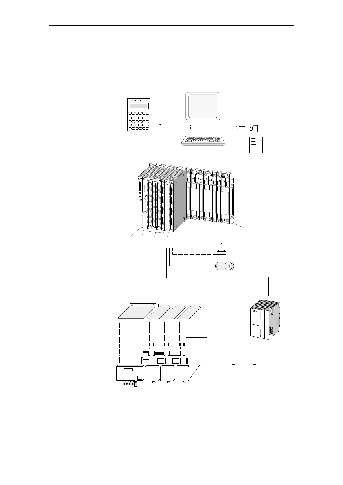
System Overview
A positioning controller using the FM 453 consists of a variety of individual
components, which are shown in Figure 1-1.
Operator panel (OP)
(e.g. OP 05)
Programming device (PG)
Configuration
package
SIMA TIC S7-400
PS CPU SMs FM 453
Power section
e.g. SIMODRIVE 61 1-A
SIMODRIVE
Fig. 1-1 System Overview (schematic)
and/or
Rack
e.g. touch
probe
Encoder (3x)
Power section
e.g. FM STEPDRIVE
and/or
Motor (3x)
e.g. 1FT5
Motor
e.g. SIMOSTEP
FM 453 Servo Drive / Step Drive Positioning Module
C79000-G7076-C453-01
1-3

Product Summary
Components
The most important components and their functions are listed in T able 1-1 .
Table 1-1 Components of a Positioning Controller
Component Function
Rack ... establish the mechanical and electrical connections
between the S7-400 modules.
FM 453 ... the positioning module. It is controlled by the
S7-400 CPU.
CPU ... executes the user program; and communicates with
the programming device and the operator panel via the
MPI interface and with the FM 453 via the backplane
bus.
Power supply (PS) ... converts line voltage (120/230 V AC) to 5 V and
Signal modules (SM) ... adapts various process-signal levels to the S7-400.
Programming device (PG) ... configures, parameterizes, programs and tests the
Operator panel (OP) ... the interface to the machine. It serves for operation
Power section ... actuates the motor.
Motor ... drives the axis.
Encoder ... the path measurement system that detects the current
Configuration
package
1)
DC operating voltage to power the S7-400
(24 V)
and performs monitoring functions.
S7-400 and the FM 453.
and monitoring. It is not an absolute prerequisite for
operation of an FM 453.
position of the axis in servo control mode. By comparing the actual position with the applicable setpoint
position, the FM 453 immediately detects discrepancies and attempts to compensate for them.
... includes:
S A manual
S 3 1/2” diskette with:
– Function-block package FCs.
– The “Parameterize FM 453” parameterization
tool.
– Preconfigured interface for the COROS device
OP 17.
1-4
1) Only for internal use in S7-400 modules
FM 453 Servo Drive / Step Drive Positioning Module
C79000-G7076-C453-01
Product Summary
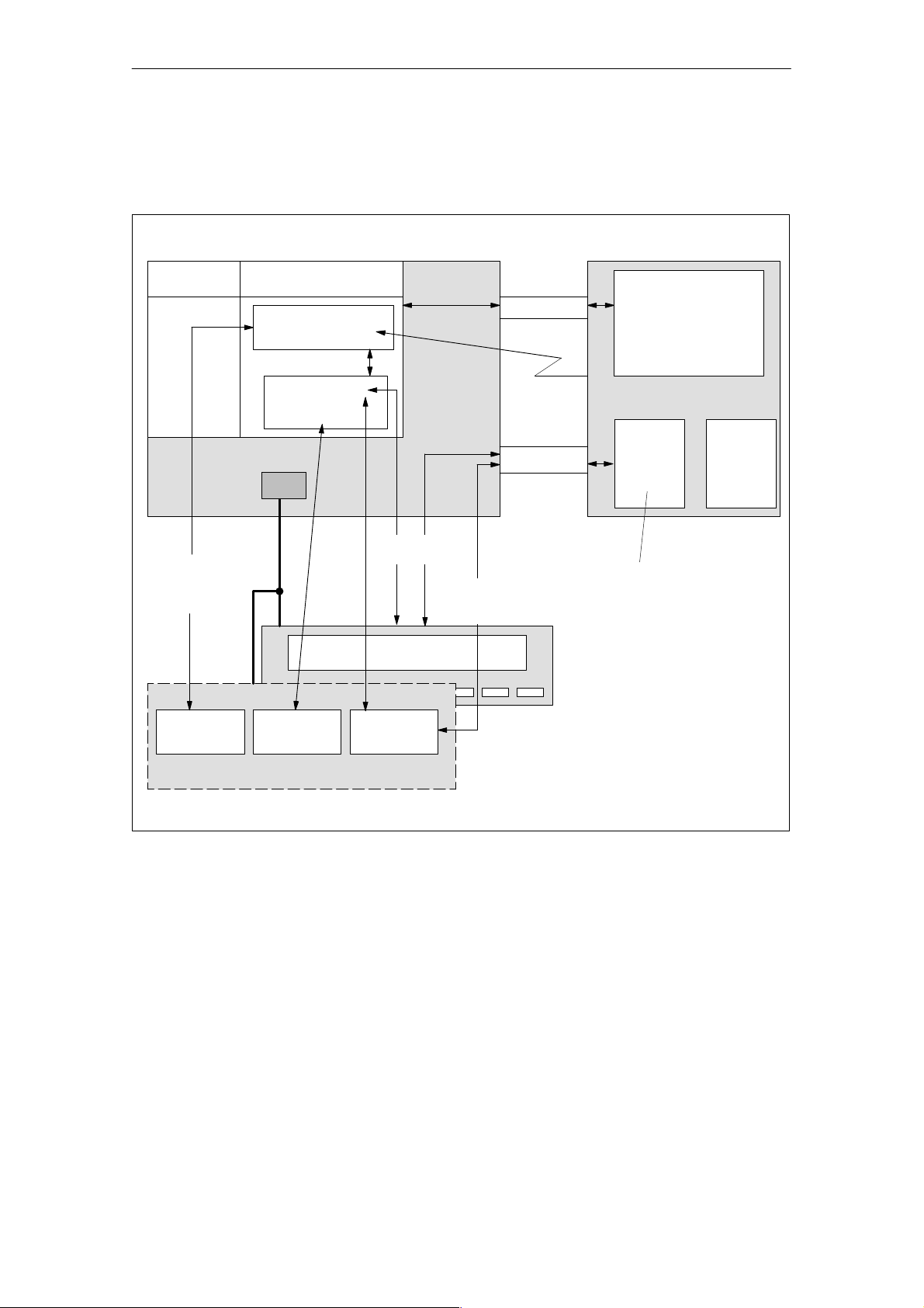
System Overview
of Data Handling
Load memory RAM
Operating system
Creation of the
user program
The following figure gives you an overview of the data storage concept.
FM 453CPU
User program, including FCs
User DBx
Online data
MPI
Module data
P bus
Diagnostic/
process interrupt
K bus
Human-machine
interface
Parameterization,
testing and diagnostics
OP
S Module data
S Diagnostic data
DBx parameterization
data
e.g.:
S Machine data
S Increments
S Tool offset data
S Traversing programs
S Status messages
-
DBx parameterization
data
LAD/STL
Editor
Fig. 1-2 Data Storage Concept
DB Editor Parameter-
PG (STEP 7)
ize FM 453
FM 453 Servo Drive / Step Drive Positioning Module
C79000-G7076-C453-01
1-5
Product Summary
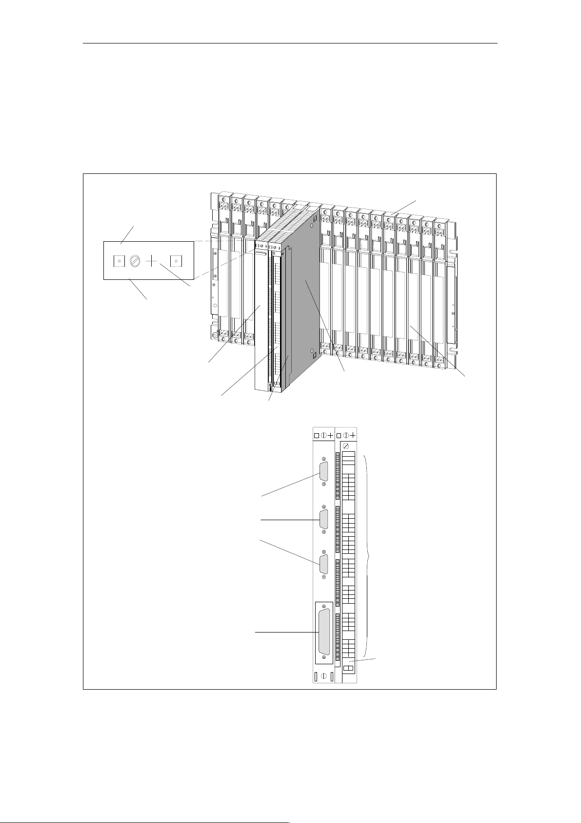
1.2 Module Description
View of the FM 453
Module identifier
FM 453
453-3AH00-0AE0
Short order No.
(6ES7 453-3AH00-0AE0)
X
2
34
Product status
Cover
Labeling plate
Figure 1-3 shows the FM 453 module, its interfaces and front-panel elements
(including fault and status displays).
Rack
Front connector
Type plate
Front view without connector cover
Bus connector SIMA TIC port
Measurement system ports X2 to X4
Drive port X5
Fig. 1-3 View of the Ports and Front-Panel Elements
1-6
Status and error displays
I/O port X1
FM 453 Servo Drive / Step Drive Positioning Module
C79000-G7076-C453-01

Product Summary
Ports
LED Indicators
A description of the ports is provided in T able 1-2 .
Table 1-2 Ports
Ports Description
Bus connector SIMATIC port
Drive port 50-pin male Sub-D connector (X5) to connect the
Measurement system port 15-pin female sub-D connector (X2 to X4) to connect
I/O port 48-pin male front connector (X1) to connect the auxil-
Rear connectors to continue the S7 buses (P and K
buses) to each module
power sections for up to three analog or step drives
the encoder
iary power supply and for digital input and output wiring
Thirty-three LEDs are arranged on the front panel of the FM 453. T able 1-3
describes these LEDs and what they mean.
Table 1-3 Status and Error Displays
LED Significance
INTF (rot) –
Internal errors
EXTF (rot) –
External errors
STAT (yellow) –
Status
I0...I3 (green) Digital Inputs
Q0...Q3 (green) Digital outputs
NL (green) – These LEDs indicate which input is ON (zero position for
READY2 (green) –
Drive unit ready
This LED indicates an error condition in the FM 453.
(see Troubleshooting, Chapter 11)
This LED indicates an error condition outside the FM 453. (see
Troubleshooting, Chapter 11)
This LED indicates various statuses (flashing). (see Troubleshooting, Chapter 11)
These LEDs indicate which input is ON (channels 1 to 3).
These LEDs indicate which output is ON (channels 1 to 3).
channels 1 to 3).
These LEDs indicate that the drive units are ready (READY2)
for operation (channels 1 to 3).
FM 453 Servo Drive / Step Drive Positioning Module
C79000-G7076-C453-01
1-7

Product Summary
Type Plate of the
FM 453
Figure 1-4 describes all the information contained in the type plate of the
FM 453.
SIEMENS
The SIMATIC S7
1
P
6ES7 453-3AH00- 0AE0
SVP JM123456
2
3456X
Made in
Germany
Serial number
Product status
Order number
Fig. 1-4 Type Plate of the FM 453
FM
APPROVED
CLASS 1 DIV 2
Group A,B,C,D
T4A
X234567
FM 453
LISTED 69B1
APPROVED
IND. CONT. EQ.
8
Marks and approvals
Module identifier
1-8
FM 453 Servo Drive / Step Drive Positioning Module
C79000-G7076-C453-01

1.3 Overview of Module Functions for Each Channel
Product Summary
Summary
Operating Mode
Control
The FM 453 module performs the following functions:
S Mode control
S Actual-value capture
S Servo position control
S Parameterizing the control mode
S Digital inputs and outputs
S Settings and functions that do not depend on operating mode
S Software limit switches
S Process interrupts
S Block sequence control
S Diagnostics and troubleshooting
S Data storage on the FM 453
The user program passes the operating mode to the FM.
The FM 453 has the following modes available:
S Jogging
S Open-loop control
Encoders
Servo Position
Control
S Reference point approach
S Incremental mode, relative
S Manual data input (MDI)
S Automatic
S Automatic single block
Incremental or absolute encoders (SSI) may be connected to the measuring
system port.
Setpoint processing is performed in the FM 453 via the following functions:
S Interpolation
S Servo position control
S Stepper motor control
S Actuating signal driver
S Drive actuation
FM 453 Servo Drive / Step Drive Positioning Module
C79000-G7076-C453-01
1-9

Product Summary
Parameterization
of the Control
Modes
Digital Inputs/
Outputs
Settings and Functions Not Dependent on Operating
Mode
In the parameterization, the following control modes can be set:
S Servomotor with servo position control
S Stepper motor with servo position control
S Stepper motor without servo position control
Four digital inputs and four digital outputs for each channel can be used specifically to a given application.
You can connect:
S Reference-point switches
S Switches for external starting
S T ouch probes
S Position reached, Stop (“PEH”)
S Forward/backward rotation
The switching function is assigned to a given I/O number by way of the machine data.
Special functions can be activated by specific settings in the user program,
in addition to the mode (e.g. measurement on-the-fly, retrigger reference
point, etc.).
Software Limit
Switches
Process Interrupts
Block Sequence
Control
Diagnostics and
Troubleshooting
Data Storage on
the FM 453
The operating range (specified by software limit switches) is automatically
monitored after synchronization is recorded.
Process interrupts are triggered by such events as:
S Position reached
S Length measurement completed
S On-the-fly block change
S Measurement on-the-fly
Process interrupts are selected by way of machine data.
Automatic processing of a traversing program, including subprograms
created during the parameterization process. A number of traversing programs are available for execution on the module.
Startup and ongoing operation of the module are monitored by fault and diagnostic interrupts. Faults or errors are reported to the system and displayed by
the LEDs on the module.
Parameterization data (machine data, tool compensation data, traversing programs and increment sizes) is retained in storage on the FM 453.
1-10
FM 453 Servo Drive / Step Drive Positioning Module
C79000-G7076-C453-01
Basic Principles of Positioning
2
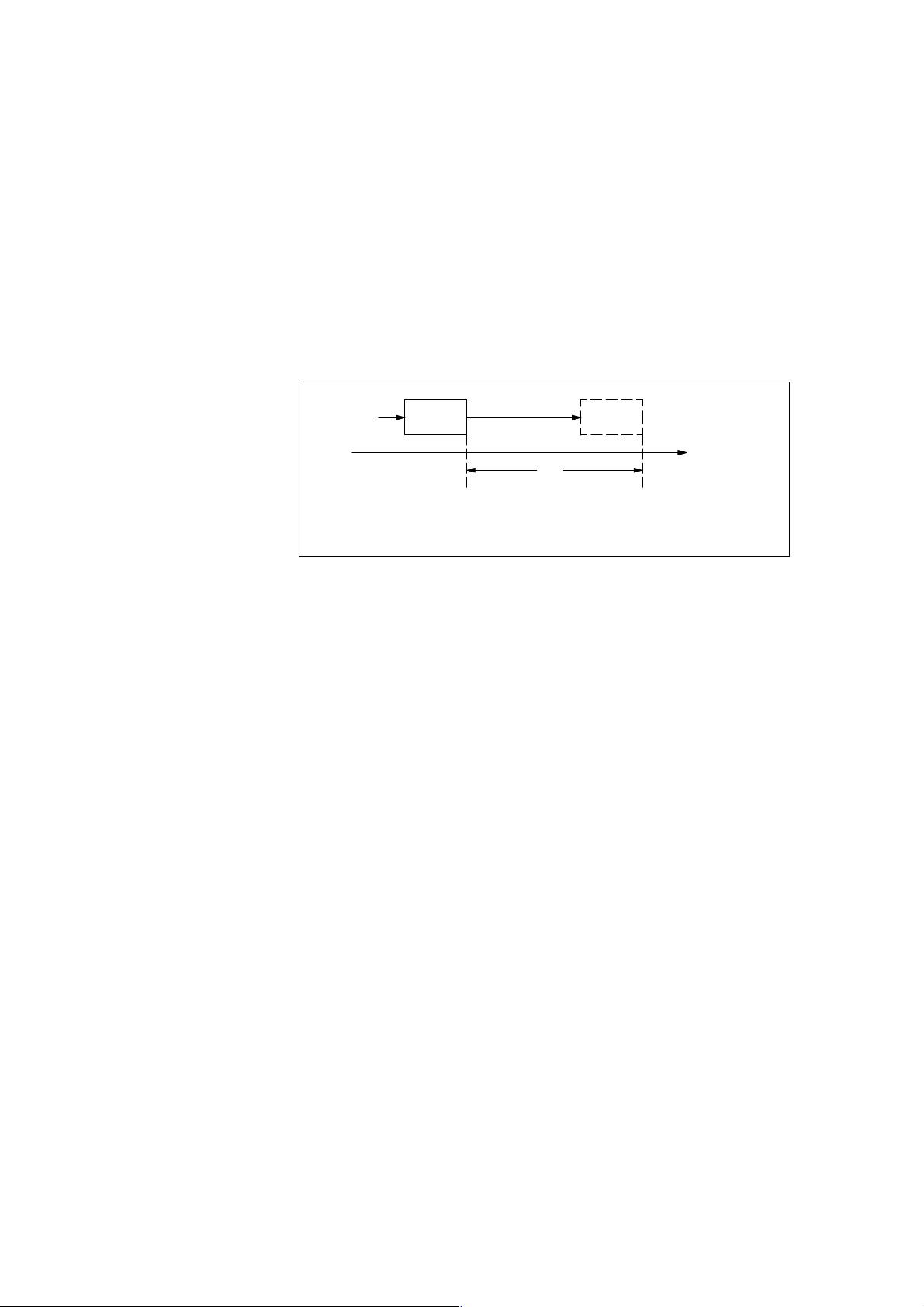
What Is Positioning?
Servo-controlled
Positioning with
Encoder
Positioning means moving a load to a defined position within a defined time,
taking all influencing forces and torques into account.
F
s
x
Position A Position B
s = pathx = distance to be traversedF = driving force
Fig. 2-1 Principle of a Positioning Action
Servo-controlled positioning is:
S Control of the drive at the right speed while a movement is being per-
formed.
S Specifying a target position and true-to-target axis approach into pro-
grammed target position
S Acquisition of the actual value at the connected encoder (incremental or
absolute)
S Maintaining the axis in position in the face of interfering factors.
S For servo motors, the 10 V port is used
S For stepper motors, the pulse/direction outputs are used
Open-loop Controlled
Positioning with
Stepper Motor
FM 453 Servo Drive / Step Drive Positioning Module
C79000-G7076-C453-01
Positioning with stepper motors is:
S Control of the drive at the right speed while a movement is being per-
formed.
S Specifying a target position and true-to-target axis approach into pro-
grammed target position
S Generating the actual value via the pulse/direction signals
2-1

Basic Principles of Positioning
Arrangement of
the Positioning
Equipment
EMERG.
STOP
Safety
device
Figure 2-2 shows the structure of a position control circuit with the FM 453
for one channel.
Power
grid
Power
section
Actuating
signal
Movement
Actual
position
PG/PC
CPUFM 453
Parameterizing/Programming
Motor
Fig. 2-2 Setup for Positioning (example)
FM 453
M
Positioning with the output of an analog actuating signal for the servo drive
or pulses for the step drive.
Power Section
The power section processes the actuating signal and delivers the proper electric power to the motor.
The power section can be:
S A servo drive, e.g. SIMODRIVE 611-A
Mechanical transmission elements
Encoder
Hardware limit
switch
“Parameterize FM 453”
“Function blocks”
2-2
S A step drive, e.g. STEPDRIVE
FM 453 Servo Drive / Step Drive Positioning Module
C79000-G7076-C453-01

Basic Principles of Positioning
Motor
Encoder
CPU
Mechanical Transmission Elements
Peripherals
The motor is actuated by the power section and drives the axis.
The motor can be:
S A servo motor, e.g. 1FT5
S A stepper motor, e.g. SIMOSTEP
The encoder detects movement of the axis. It supplies pulses to the FM 453.
The number of pulses is proportional to the distance traversed. Stepper motor
operation is also possible without the encoder.
The CPU executes the user program.
These include not only the axis, but also gear trains and clutch systems.
All other additional equipment is covered by the term peripherals.
Peripherals mainly include:
S Limit switches to limit the positioning range (safety devices).
S The programming device/PC is used for:
– Assigning parameters using the software “Parameterize FM 453”
– Programming the FM 453 using function blocks
– Test/startup
FM 453 Servo Drive / Step Drive Positioning Module
C79000-G7076-C453-01
2-3

Basic Principles of Positioning
2-4
FM 453 Servo Drive / Step Drive Positioning Module
C79000-G7076-C453-01

Installing and Removing the FM 453
3
Overview
Mechanical Set-Up
Important Safety
Rules
Module Replacement
Chapter
Overview
The FM 453 positioning module can be installed, in the same manner as a
signal module, in a central controller or in an expansion unit (EUs 1 to 6).
The options for the mechanical set-up and its configuration are described in
the manual S7-400/M7-400 Programmable Controller; Hardware and Instal-
lation.
There are important rules which you must follow when integrating an FM
453 in the S7-400 PLC in a plant or system.
These rules and specifications are described in the manual S7-400/M7-400
Programmable Controller, Hardware and Installation .
A module can be replaced during operation of the programmable controller.
In Section You Will Find On Page
3.1 Installing the FM 453 3-2
3.2 Removing the FM 453 3-3
3.3 Replacing Modules 3-3
FM 453 Servo Drive / Step Drive Positioning Module
C79000-G7076-C453-01
3-1

Installing and Removing the FM 453
3.1 Installing the FM 453
Rules
Tools Required
Procedure
No particular protective measures (EGB Guidelines) are necessary for the
installation of the FM 453.
Note
Please refer to Appendix B in the manual S7-400/M7-400 Programmable
Controller, Hardware and Installation.
A 4.5 mm (0.18 inch) screwdriver.
T o install the FM 453:
1. Hook the FM 453 onto the rail and swing it into position.
2. Screw the FM 453 down (torque approx. 0.8 to 1.1 Nm).
3. Attach the sub-D plugs to the encoder and drive unit.
4. Attach the front connector.
5. Fit the connector cover and lock it in place.
6. After the modules have been mounted, you can also assign each of them a
slot number. Slot labels for this purpose are enclosed with the rack.
The numbering scheme and how to plug in the slot labels are described in
the manual S7-400/M7-400 Programmable Controller, Hardware and
Installation .
Note
The slot determines the initial address of each module.
3-2
FM 453 Servo Drive / Step Drive Positioning Module
C79000-G7076-C453-01
 Loading...