

Siemens SIMATIC FM 353 User Manual

Preface, Contents
SIMATIC
FM 353
Stepper Drive Positioning
Module
Manual
Product Overview
Basic Principles of Positioning
Installing and Removing
Wiring
Defining Parameters
Programming the Technological
Functions
Starting up
Human-machine Interface
Description of Functions
1
2
3
4
5
6
7
8
9
6ES7 353-1AH01-8BG0
04/2007 Edition
Writing Traversing Programs
Troubleshooting
Appendices
Technical Specifications
User Data Block (AW−DB)
List of Abbreviations
Index
10
11
A
B
C

Safety Information
This Manual contains information which you should carefully observe to ensure your own personal
safety and the prevention of damage to the system. This information is highlighted by a warning
triangle and presented in one of the following ways depending on the degree of risk involved:
Danger
!
indicates that death or severe personal injury damage will result if proper precautions are not taken.
Warning
!
indicates that death or severe personal injury damage can result if proper precautions are not taken.
Caution
!
indicates that minor personal injury can result if proper precautions are not taken.
Caution
without warning sign means that material damage can occur if the appropriate precautions are not taken.
Attention
means that an undesired result or a condition may occur if the appropriate note is not observed.
If more than one level of hazard can occur, the warning note of the correspondingly highest level is used in
all cases. If a warning note with a warning triangle warns of personal injury, an additional warning of
material damage can be included in the same warning note.
Qualified personnel
The unit may only be started up and operated by qualified personnel. Qualified personnel
as referred to in the safety guidelines in this document are those who are authorized to start up, earth
and label units, systems and circuits in accordance with relevant safety standards.
Proper use
Please note the following:
Warning
!
Trademarks
The unit may be used only for the applications described in the catalog or the technical description,
and only in combination with the equipment, components and devices of other manufacturers as far
as this is recommended or permitted by Siemens.
It is assumed that this product be transported, stored and installed as intended and maintained and
operated with care to ensure that the product functions correctly and safely.
All names marked with the copyright notice R are registered trademarks of SIEMENS AG.
Other names in this publication might be trademarks whose use by a third party for his own purposes
may violate the rights of the registered holder.
Exclusion of liabilityCopyright Siemens AG. 1996-2007 All rights reserved
The reproduction, transmission or use of this document or its contents is not
permitted without express written authority. Offenders will be liable for
damages. All rights, including rights created by patent grant or registration of
a utility model, are reserved.
Siemens AG
Automation & Drives
90437 Nürnberg
Federal Republic of Germany
Index-2
Siemens Aktiengesellschaft 6ES7-353-1AH01-8BG0
We have checked that the contents of this publication agree with the hardware and software described herein. Nonetheless, differences might exist
and therefore we cannot guarantee that they are completely identical. The
information given in this publication is reviewed at regular intervals and any
corrections that might be necessary are made in the subsequent printings.
E Siemens AG 1996-2007
Subject to change without prior notice.
FM 353 Stepper Drive Positioning Module
6ES7 353-1AH01-8BG0

Preface
Information
This manual contains all information about the FM 353 module:
S Hardware and functions
S Parameterization
S Human-machine interface
S S7 blocks
S Safe design
Information blocks in this manual
The following information blocks describe the purpose and application of this
manual:
S Product overview of the module (Chapter 1)
This section explains the purpose and possible applications of the module. It
provides introductory information about the FM 353 and its functions.
S Basic principles of positioning (Chapter 2)
Here you will find introductory information on positioning methods and associated definitions of terms.
S Installing and removing the FM 353 (Chapter 3)
Explains the installation and removal of the FM 353.
S Wiring the FM 353 (Chapter 4)
Describes the connection and wiring of drives and digital input/output modules.
S Defining parameters of the FM 353 (Chapter 5)
Describes the parameterization and functions of “Parameterize FM 357.”
S Programming the FM 353 (Chapter 6)
Describes how to program the FM 357 with STEP 7.
S Starting up the FM 353 (Chapter 7)
Describes startup procedures for the FM 353.
S Human-machine interface (Chapter 8)
Describes the various options for operating and monitoring the FM 353, and
which data and signals can be used and monitored.
FM 353 Stepper Drive Positioning Module
6ES7 353-1AH01-8BG0
i

Preface
S Reference information and appendices for finding factual information (module
functions, programming guide, interface signals, error handling, technical specifications, standard HMI user interface)
S List of abbreviations and index for looking up information.
User requirements
The present manual describes the hardware and functions of the FM 353
To set up, program and start up a SIMATIC S7-300 with the FM 353, you will need
a knowledge of:
S The SIMATIC S7
Installation manual S7-400/M7−400 Programmable Controller, Hardware and
Installation
S Your programming device (PG)
S How to perform programming with STEP 7
S How to configure an operator panel interface.
FM 353 users
The structure and presentation of the information in the manual are oriented to the
intended uses of the FM 353, and the user’s own activity.
It distinguishes among the following:
S Installation and wiring
S Parameterizing and Programming
S Troubleshooting and diagnostics
S Operation
Note
These activities include installation and wiring of the FM 353.
These activities include parameterizing and programming the FM 353.
These activities include detecting and correcting faults and errors
− in the hardware setup of the module and its components
− and in the programming, handling and control of module functions.
These users operate the FM 353. The operator accordingly deals only with the
control of positioning tasks.
The PROFINET functionality described in the present manual (in the current
version) is only available on request. Please get in touch with your Siemens
contact partner.
ii
FM 353 Stepper Drive Positioning Module
6ES7 353-1AH01-8BG0

Standards and approvals
Our products are in compliance with the EU Guideline 89/336/EEC “Electromagnetic Compatibility” and the harmonized European standards (EN) which it embodies.
The current version of the EC Declaration of Conformity can be found on the
Internet at
http://support.automation.siemens.com/WW/view/de/15257461
Recycling and disposal
For recycling in an environmentally compatible manner and for the disposal of your
old SIMATIC in line with prsent state of technology, please contact your appropriate Siemens contact partner:
http://www.automation.siemens.com/partner
Technical support
Preface
If you have any technical question, please do no hesitate to contact our hotline:
Time zone: Europe/Africa Asia/Australia America
Telephone +49 (0) 180 5050 222 +86 1064 719 990 +1 423 262 2522
Fax +49 (0) 180 5050 223 +86 1064 747 474 +1 423 262 2289
Internet http://www.siemens.com/automation/support-request
E-mail adsupport@siemens.com
Note
The country−specific telephone numbers for technical consultation can be found
on the Internet at: http://www.siemens.com/automation/service&support
Questions regarding this Manual
If you have any questions regarding this Documentation (suggestions, corrections),
please send a fax or an e−mail to the following address:
Fax: +49 (0) 9131 98 63 315
E-mail: docu.motioncontrol@siemens.com
Siemens Internet address
For currently updated information on the SIMATIC products, vitsit us on the Internet at: http://www.siemens.de/simatic.
FM 353 Stepper Drive Positioning Module
6ES7 353-1AH01-8BG0
iii

Preface
Further support
We are offering courses to help you familiarize yourself with the operation of the
SIMATIC S7 programmable controller system.
Please contact your regional or the central training center in D-90027 Nürnberg,
Germany under tel. +49 911-89 53 202.
J
iv
FM 353 Stepper Drive Positioning Module
6ES7 353-1AH01-8BG0

Table of Contents
1 Product Overview 1-1 . . . . . . . . . . . . . . . . . . . . . . . . . . . . . . . . . . . . . . . . . . . . . . . . . . . . . .
1.1 The FM 353 in the S7-300 programmable controller 1-2 . . . . . . . . . . . . . . . . . .
1.2 Module description 1-7 . . . . . . . . . . . . . . . . . . . . . . . . . . . . . . . . . . . . . . . . . . . . . .
1.3 Overview of module functions 1-9 . . . . . . . . . . . . . . . . . . . . . . . . . . . . . . . . . . . . .
2 Basic Principles of Positioning 2-1 . . . . . . . . . . . . . . . . . . . . . . . . . . . . . . . . . . . . . . . . . .
3 Installing and Removing 3-1 . . . . . . . . . . . . . . . . . . . . . . . . . . . . . . . . . . . . . . . . . . . . . . . .
3.1 Installing the FM 353 3-3 . . . . . . . . . . . . . . . . . . . . . . . . . . . . . . . . . . . . . . . . . . . .
3.2 Removing the FM 353 3-4 . . . . . . . . . . . . . . . . . . . . . . . . . . . . . . . . . . . . . . . . . . .
3.3 Replacing modules 3-5 . . . . . . . . . . . . . . . . . . . . . . . . . . . . . . . . . . . . . . . . . . . . . .
4 Wiring 4-1 . . . . . . . . . . . . . . . . . . . . . . . . . . . . . . . . . . . . . . . . . . . . . . . . . . . . . . . . . . . . . . . . .
4.1 Wiring an FM 353 4-2 . . . . . . . . . . . . . . . . . . . . . . . . . . . . . . . . . . . . . . . . . . . . . . .
4.2 Description of the drive interface 4-4 . . . . . . . . . . . . . . . . . . . . . . . . . . . . . . . . . .
4.3 Connecting the drive unit 4-11 . . . . . . . . . . . . . . . . . . . . . . . . . . . . . . . . . . . . . . . . .
4.4 Description of the I/O interface 4-12 . . . . . . . . . . . . . . . . . . . . . . . . . . . . . . . . . . . .
4.5 Wiring up the front connector 4-18 . . . . . . . . . . . . . . . . . . . . . . . . . . . . . . . . . . . . .
5 Defining Parameters 5-1 . . . . . . . . . . . . . . . . . . . . . . . . . . . . . . . . . . . . . . . . . . . . . . . . . . . .
5.1 Installing “Parameterize FM 353” 5-3 . . . . . . . . . . . . . . . . . . . . . . . . . . . . . . . . . .
5.2 Getting started with “Parameterize FM 353” 5-4 . . . . . . . . . . . . . . . . . . . . . . . . .
5.3 Parameter data 5-7 . . . . . . . . . . . . . . . . . . . . . . . . . . . . . . . . . . . . . . . . . . . . . . . . .
5.3.1 Machine data 5-9 . . . . . . . . . . . . . . . . . . . . . . . . . . . . . . . . . . . . . . . . . . . . . . . . . .
5.3.2 Increments 5-20 . . . . . . . . . . . . . . . . . . . . . . . . . . . . . . . . . . . . . . . . . . . . . . . . . . . . .
5.3.3 Tool offset data 5-21 . . . . . . . . . . . . . . . . . . . . . . . . . . . . . . . . . . . . . . . . . . . . . . . . .
5.3.4 Traversing programs 5-23 . . . . . . . . . . . . . . . . . . . . . . . . . . . . . . . . . . . . . . . . . . . .
5.4 Parameterization with “Parameterize FM 353” 5-25 . . . . . . . . . . . . . . . . . . . . . . .
5.5 Storing the parameter data in SDB 1 000 5-26 . . . . . . . . . . . . . . . . . . . . . . . .
6 Programming the Technological Functions 6-1 . . . . . . . . . . . . . . . . . . . . . . . . . . . . . . .
6.1 Programming fundamentals 6-4 . . . . . . . . . . . . . . . . . . . . . . . . . . . . . . . . . . . . . . .
6.1.1 Communication between the CPU and the FM 353 6-4 . . . . . . . . . . . . . . . . . . .
6.1.2 Structure of a user program 6-5 . . . . . . . . . . . . . . . . . . . . . . . . . . . . . . . . . . . . . . .
6.1.3 Distributed configuration, OB 86 6-6 . . . . . . . . . . . . . . . . . . . . . . . . . . . . . . . . . . .
6.1.4 Embedding an OP 6-6 . . . . . . . . . . . . . . . . . . . . . . . . . . . . . . . . . . . . . . . . . . . . . . .
6.1.5 Procedure for writing the user program (AWP) 6-7 . . . . . . . . . . . . . . . . . . . . . . .
6.2 Putting the FM 353 into operation with the parameter initialization tool 6-8 . .
FM 353 Stepper Drive Positioning Module
6ES7 353-1AH01-8BG0
v

Table of Contents
6.3 Standard function blocks of the “FMSTSV_L” block library 6-8 . . . . . . . . . . . .
6.3.1 Overview of the “FMSTSV_L” function block library 6-9 . . . . . . . . . . . . . . . . . .
6.3.2 The POS_INIT (FC 0) block − Initialization 6-10 . . . . . . . . . . . . . . . . . . . . . . . . . .
6.3.3 The POS_CTRL (FC 1) block − Data exchange 6-12 . . . . . . . . . . . . . . . . . . . . .
6.3.4 The POS_DIAG (FC 2) block − Read diagnostic interrupt data 6-22 . . . . . . . . .
6.3.5 The POS_MSRM (FC 3) block − Read measured values 6-25 . . . . . . . . . . . . .
6.3.6 Interface, user data blocks (AW-DBs) 6-26 . . . . . . . . . . . . . . . . . . . . . . . . . . . . . .
6.4 Standard function blocks of the “FM353_354” block library
(also for PROFINET, upon request) 6-28 . . . . . . . . . . . . . . . . . . . . . . . . . . . . . . . .
6.4.1 Overview of the “FM353_354” block library 6-28 . . . . . . . . . . . . . . . . . . . . . . . . .
6.4.2 The POS_INIT (FC 0) block − Initialization 6-30 . . . . . . . . . . . . . . . . . . . . . . . . . .
6.4.3 The POS_CTRL (FC 1) block − Data exchange 6-30 . . . . . . . . . . . . . . . . . . . . .
6.4.4 The POS_DIAG (FC 2) block − Read diagnostic interrupt data 6-41 . . . . . . . . .
6.4.5 The POS_MSRM (FC 3) block − Read measured values 6-41 . . . . . . . . . . . . .
6.4.6 Interface, user DBs (AW-DBs) 6-42 . . . . . . . . . . . . . . . . . . . . . . . . . . . . . . . . . . . .
6.5 Interrupts 6-44 . . . . . . . . . . . . . . . . . . . . . . . . . . . . . . . . . . . . . . . . . . . . . . . . . . . . . . .
6.6 User data block (AW-DB) 6-46 . . . . . . . . . . . . . . . . . . . . . . . . . . . . . . . . . . . . . . . . .
6.7 Sample applications 6-57 . . . . . . . . . . . . . . . . . . . . . . . . . . . . . . . . . . . . . . . . . . . . .
6.8 Error list, system messages (CPU) 6-64 . . . . . . . . . . . . . . . . . . . . . . . . . . . . . . . .
6.9 Technical specifications 6-66 . . . . . . . . . . . . . . . . . . . . . . . . . . . . . . . . . . . . . . . . . .
7 Starting up 7-1 . . . . . . . . . . . . . . . . . . . . . . . . . . . . . . . . . . . . . . . . . . . . . . . . . . . . . . . . . . . . .
7.1 Installation and wiring 7-2 . . . . . . . . . . . . . . . . . . . . . . . . . . . . . . . . . . . . . . . . . . . .
7.2 Initial values for testing and optimization 7-3 . . . . . . . . . . . . . . . . . . . . . . . . . . . .
7.3 Testing and optimization 7-7 . . . . . . . . . . . . . . . . . . . . . . . . . . . . . . . . . . . . . . . . . .
7.3.1 Activating the machine data 7-13 . . . . . . . . . . . . . . . . . . . . . . . . . . . . . . . . . . . . . . .
7.3.2 Evaluating the characteristics of the stepper motor 7-14 . . . . . . . . . . . . . . . . . . .
7.3.3 Basic startup of stepper motor control 7-18 . . . . . . . . . . . . . . . . . . . . . . . . . . . . . .
7.3.4 Optimization of dynamic response 7-21 . . . . . . . . . . . . . . . . . . . . . . . . . . . . . . . . .
7.3.5 Realigning the reference point coordinates 7-24 . . . . . . . . . . . . . . . . . . . . . . . . . .
7.3.6 Activating stepper motor diagnostics 7-25 . . . . . . . . . . . . . . . . . . . . . . . . . . . . . . .
7.3.7 Activating the software limit switches and backlash compensation 7-26 . . . . .
7.3.8 Optimized motion profile 7-28 . . . . . . . . . . . . . . . . . . . . . . . . . . . . . . . . . . . . . . . . . .
8 Human-machine Interface 8-1 . . . . . . . . . . . . . . . . . . . . . . . . . . . . . . . . . . . . . . . . . . . . . . .
8.1 Standard HMI (human-machine interface) for the OP 07 and
the OP 17 8-3 . . . . . . . . . . . . . . . . . . . . . . . . . . . . . . . . . . . . . . . . . . . . . . . . . . . . . .
8.1.1 Standard user interface for the OP 07 8-5 . . . . . . . . . . . . . . . . . . . . . . . . . . . . . .
8.1.2 Standard user interface for the OP 17 8-10 . . . . . . . . . . . . . . . . . . . . . . . . . . . . . .
8.2 Analysis of the user DB by the user program for operator control 8-17 . . . . . .
8.3 Data block for status messages (DB-SS) 8-20 . . . . . . . . . . . . . . . . . . . . . . . . . . .
9 Description of Functions 9-1 . . . . . . . . . . . . . . . . . . . . . . . . . . . . . . . . . . . . . . . . . . . . . . . .
9.1 Control and checkback signals 9-2 . . . . . . . . . . . . . . . . . . . . . . . . . . . . . . . . . . . .
9.1.1 Control signals 9-3 . . . . . . . . . . . . . . . . . . . . . . . . . . . . . . . . . . . . . . . . . . . . . . . . . .
9.1.2 Checkback signals 9-6 . . . . . . . . . . . . . . . . . . . . . . . . . . . . . . . . . . . . . . . . . . . . . .
9.1.3 General handling information 9-10 . . . . . . . . . . . . . . . . . . . . . . . . . . . . . . . . . . . . . .
vi
FM 353 Stepper Drive Positioning Module
6ES7 353-1AH01-8BG0

Table of Contents
9.2 Operating modes 9-14 . . . . . . . . . . . . . . . . . . . . . . . . . . . . . . . . . . . . . . . . . . . . . . . .
9.2.1 Jogging 9-15 . . . . . . . . . . . . . . . . . . . . . . . . . . . . . . . . . . . . . . . . . . . . . . . . . . . . . . . .
9.2.2 Open-loop control 9-18 . . . . . . . . . . . . . . . . . . . . . . . . . . . . . . . . . . . . . . . . . . . . . . .
9.2.3 Reference point approach 9-19 . . . . . . . . . . . . . . . . . . . . . . . . . . . . . . . . . . . . . . . .
9.2.4 Incremental relative 9-24 . . . . . . . . . . . . . . . . . . . . . . . . . . . . . . . . . . . . . . . . . . . . . .
9.2.5 MDI (Manual Data Input) 9-27 . . . . . . . . . . . . . . . . . . . . . . . . . . . . . . . . . . . . . . . . .
9.2.6 Automatic 9-31 . . . . . . . . . . . . . . . . . . . . . . . . . . . . . . . . . . . . . . . . . . . . . . . . . . . . . .
9.2.7 Automatic single block 9-36 . . . . . . . . . . . . . . . . . . . . . . . . . . . . . . . . . . . . . . . . . . .
9.3 System data 9-37 . . . . . . . . . . . . . . . . . . . . . . . . . . . . . . . . . . . . . . . . . . . . . . . . . . . .
9.3.1 Change parameters/data (Write request in user DB, DBX39.3) 9-38 . . . . . . . .
9.3.2 Single functions (user DB, DBB34 and 35) 9-42 . . . . . . . . . . . . . . . . . . . . . . . . . .
9.3.3 Single functions (user DB, DBB36 and 37) 9-44 . . . . . . . . . . . . . . . . . . . . . . . . . .
9.3.4 Zero offset (Write request in the user DB, DBX39.1) 9-46 . . . . . . . . . . . . . . . . .
9.3.5 Set actual value (Write request in the user DB, DBX38.7) 9-48 . . . . . . . . . . . . .
9.3.6 Set actual value on-the-fly (Write request in the user DB, DBX39.0) 9-49 . . . .
9.3.7 Request application data (Write request in the user DB, DBX39.6) 9-50 . . . . .
9.3.8 Teach in (Write request in the user DB, DBX39.7) 9-51 . . . . . . . . . . . . . . . . . . . .
9.3.9 Set reference point (Write request in the user DB, DBX38.6) 9-51 . . . . . . . . . .
9.3.10 Measured values 9-52 . . . . . . . . . . . . . . . . . . . . . . . . . . . . . . . . . . . . . . . . . . . . . . .
9.3.11 Basic operating data (Read request in the user DB, DBX42.0) 9-55 . . . . . . . . .
9.3.12 Active NC block (Read request in the user DB, DBX42.1),
next NC block (Read request in the user DB, DBX42.2) 9-56 . . . . . . . . . . . . . .
9.3.13 Application data (Read request in the user DB, DBX43.6) 9-57 . . . . . . . . . . . . .
9.3.14 Actual value block change (Read request in the user DB, DBX42.3) 9-57 . . . .
9.3.15 Servicing data (Read request in the user DB, DBX42.4) 9-57 . . . . . . . . . . . . . .
9.3.16 Additional operating data (Read request in the user DB, DBX43.5) 9-58 . . . . .
9.3.17 Parameters/data (Read request in the user DB, DBX43.3) 9-58 . . . . . . . . . . . .
9.4 System of measurement 9-59 . . . . . . . . . . . . . . . . . . . . . . . . . . . . . . . . . . . . . . . . .
9.5 Axis type 9-60 . . . . . . . . . . . . . . . . . . . . . . . . . . . . . . . . . . . . . . . . . . . . . . . . . . . . . . .
9.6 Determining the position 9-63 . . . . . . . . . . . . . . . . . . . . . . . . . . . . . . . . . . . . . . . . . .
9.6.1 Synchronizing the stepper motor axis 9-64 . . . . . . . . . . . . . . . . . . . . . . . . . . . . . .
9.7 Stepper motor control system 9-66 . . . . . . . . . . . . . . . . . . . . . . . . . . . . . . . . . . . . .
9.7.1 Frequency generation 9-69 . . . . . . . . . . . . . . . . . . . . . . . . . . . . . . . . . . . . . . . . . . .
9.7.2 Drive interface 9-71 . . . . . . . . . . . . . . . . . . . . . . . . . . . . . . . . . . . . . . . . . . . . . . . . . .
9.7.3 Rotation monitoring 9-75 . . . . . . . . . . . . . . . . . . . . . . . . . . . . . . . . . . . . . . . . . . . . .
9.8 Digital inputs/outputs (Read request user DB, DBX43.4) 9-77 . . . . . . . . . . . . . .
9.8.1 Function description for digital inputs 9-78 . . . . . . . . . . . . . . . . . . . . . . . . . . . . . . .
9.8.2 Function description for digital outputs
(Write request in the user DB, DBX39.4) 9-79 . . . . . . . . . . . . . . . . . . . . . . . . . . . .
9.9 Software limit switches 9-80 . . . . . . . . . . . . . . . . . . . . . . . . . . . . . . . . . . . . . . . . . . .
9.10 Process interrupts 9-81 . . . . . . . . . . . . . . . . . . . . . . . . . . . . . . . . . . . . . . . . . . . . . . .
10 Writing Traversing Programs 10-1 . . . . . . . . . . . . . . . . . . . . . . . . . . . . . . . . . . . . . . . . . . . .
10.1 Traversing blocks 10-2 . . . . . . . . . . . . . . . . . . . . . . . . . . . . . . . . . . . . . . . . . . . . . . .
10.2 Program execution and direction of processing 10-16 . . . . . . . . . . . . . . . . . . . . . .
10.3 Block transitions 10-16 . . . . . . . . . . . . . . . . . . . . . . . . . . . . . . . . . . . . . . . . . . . . . . . .
FM 353 Stepper Drive Positioning Module
6ES7 353-1AH01-8BG0
vii

Table of Contents
11 Troubleshooting 11-1 . . . . . . . . . . . . . . . . . . . . . . . . . . . . . . . . . . . . . . . . . . . . . . . . . . . . . . . .
11.1 Error classes and module responses 11-3 . . . . . . . . . . . . . . . . . . . . . . . . . . . . . . .
11.2 Error messages 11-4 . . . . . . . . . . . . . . . . . . . . . . . . . . . . . . . . . . . . . . . . . . . . . . . . .
11.2.1 Fault indication by LED 11-4 . . . . . . . . . . . . . . . . . . . . . . . . . . . . . . . . . . . . . . . . . . .
11.2.2 Diagnostic interrupts 11-6 . . . . . . . . . . . . . . . . . . . . . . . . . . . . . . . . . . . . . . . . . . . .
11.2.3 Error messages in checkback signals 11-7 . . . . . . . . . . . . . . . . . . . . . . . . . . . . . .
11.2.4 Message in data block 11-8 . . . . . . . . . . . . . . . . . . . . . . . . . . . . . . . . . . . . . . . . . . .
11.2.5 Viewing the diagnostic buffer (PG/PC) 11-8 . . . . . . . . . . . . . . . . . . . . . . . . . . . . . .
11.3 Error lists 11-9 . . . . . . . . . . . . . . . . . . . . . . . . . . . . . . . . . . . . . . . . . . . . . . . . . . . . . . .
11.3.1 Diagnostic interrupts 11-9 . . . . . . . . . . . . . . . . . . . . . . . . . . . . . . . . . . . . . . . . . . . . .
11.3.2 Error messages 11-13 . . . . . . . . . . . . . . . . . . . . . . . . . . . . . . . . . . . . . . . . . . . . . . . . .
A Technical Specifications A-1 . . . . . . . . . . . . . . . . . . . . . . . . . . . . . . . . . . . . . . . . . . . . . . . .
B User Data Block (AW-DB) B-1 . . . . . . . . . . . . . . . . . . . . . . . . . . . . . . . . . . . . . . . . . . . . . . . .
C List of Abbreviations C-1 . . . . . . . . . . . . . . . . . . . . . . . . . . . . . . . . . . . . . . . . . . . . . . . . . . .
Index Index-1 . . . . . . . . . . . . . . . . . . . . . . . . . . . . . . . . . . . . . . . . . . . . . . . . . . . . . . . . . . . . . . .
viii
FM 353 Stepper Drive Positioning Module
6ES7 353-1AH01-8BG0

Product Overview
Chapter overview
Section Section Header Page
1.1 The FM 353 in the S7-300 programmable controller 1-2
1.2 Module description 1-7
1.3 Overview of the module functions 1-9
What can the FM 353 do?
The FM 353 is a microprocessor-controlled positioning module for actuating a stepper motor.
The FM 353 is a high-performance module for positioning with stepper drives.
The module works autonomously and is controlled by way of the user program in
the SIMATIC S7-300 system.
It can operate rotary and linear axes.
1
The FM 353 has a variety of operating modes.
The module has a non-volatile data memory to store parameterization data.
S The FM 353 is low-maintenance (no battery).
S It can be linked and adapted to user circumstances by parameterizing it as re-
quired by the system.
FM 353 Stepper Drive Positioning Module
6ES7 353-1AH01-8BG0
1-1

Product Overview
Where can the FM 353 be used?
The FM 353 can be used for both simple positioning and complex traversing profiles demanding superior dynamic response, accuracy and speed. It is also suitable
for positioning tasks in machinery with high clock-pulse rates.
Typical uses for the positioning module might include:
S Transfer lines
S Assembly lines
S Woodworking machines
S Handling equipment
S Loaders
S Auxiliary movements in milling and turning machines
S Packaging machines
S Conveyor equipment
Its range of functions is comparable to that of the WF 721 module in the SIMATIC
S5 system, and the FM 354 in the SIMATIC S7 system.
1.1 The FM 353 in the S7-300 programmable controller
How is the FM 353 linked up with the S7-300?
The FM 353 is designed as a function module of the SIMATIC S7-300 controller.
The S7-300 programmable controller consists of a CPU and a variety of peripheral
modules mounted on a mounting rail.
The configuration may have one or more racks.
1-2
FM 353 Stepper Drive Positioning Module
6ES7 353-1AH01-8BG0
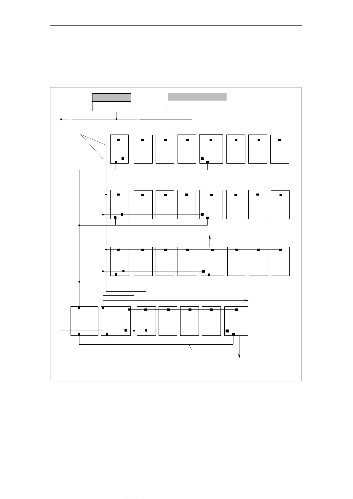
Multi-rack configurations
A SIMATIC S7-300 CPU may run up to four racks with as many as eight bus stations each (see Figure 1-1).
Product Overview
MPI
bus
Operator panel
24 V
24 V
OP
Rack 3Backplane
IM
Rack 2
IM
Rack 1
IM
PG
Programming device
SM SM SM
dig./anal. dig./anal.
SM SM
dig./anal.
SM SM
dig./anal.
dig./anal.
SM
dig./anal.
SM
dig./anal.
FM
FM
SM
dig./anal.
stepper drive
SM
dig./anal.SMdig./anal.
SM
dig./anal.
FM 353
SM
dig./anal.
dig./anal.
SM
dig./anal.
SM
dig./anal.
dig./anal.
SM
dig./anal.
SM
dig./anal.
24 V
Rack 0
PS 24 V
2/5/10 A
SIMATIC
S7-300 CPU
IM
SM
dig./anal.
SM
dig./anal.
SM
dig./anal.
FM 353
MPI − Multipoint interface
IM − Interface module
SM − Signal module
24 V
Stepper drive
PS − Power supply
CPU − Central processing unit
Fig. 1-1 Multi-rack configuration of a SIMATIC S7-300 with FM 353 (example)
Distributed I/Os,
L2-DP with IM interface
module
FM 353 Stepper Drive Positioning Module
6ES7 353-1AH01-8BG0
1-3

Product Overview
System overview
A complete positioning controller using the FM 353 consists of a variety of individual components, which are shown in Figure 1-2.
DIN rail
Operator panel (OP)
(e.g. OP 07)
PS
CPU
IM
Power section
e.g.
FM STEPDRIVE
SM
Your programming device (PG)
SIMATIC S7-300
SM
FM 353
SM
SM
Configuration package
e.g. touch probe
Fig. 1-2 System overview (schematic)
MPI connection
The FM can service up to 3 MPI nodes (PCs, programming devices or OPs) simultaneously.
Motor e.g. SIMOSTEP
1-4
FM 353 Stepper Drive Positioning Module
6ES7 353-1AH01-8BG0

Components
The most important components and their functions are listed in Table 1-1.
Table 1-1 Components of a positioning controller
Product Overview
Component
DIN rail ... the module mounting rack for the S7-300.
FM 353 ... the positioning module. It is controlled by the S7-300 CPU.
CPU ... executes the user program; powers the S7-300 backplane
bus at 5 V; and communicates with the programming device
and the operator panel via the MPI interface.
Power supply (PS) ... converts line voltage (120/230 V AC) to 24 V DC operating
voltage to power the S7-300.
Signal modules (SM) ... adapts various process-signal levels to the S7-300
Interface module (IM) ... connects the individual cells of an S7-300 with
one another (applies to multi-rack configuration; see Figure
1-1).
Programming device (PG) ... configures, parameterizes, programs and tests the S7-300
and the FM 353.
Operator panel (OP) ... the interface to the machine. It serves for operation and
monitoring. It is not an absolute prerequisite for operation of
an FM 353.
Power section ... actuates the motor.
Motor ... drives the axis.
Configuration package ... A CD-ROM containing:
Function
S An FC block package
S MD DBs (for start-up of stepper motor)
S The parameterization tool ”Parameterize FM 353”
S A preconfigured operator interface for the COROS series
OP 07 and OP 17
S A manual in PDF format
S Getting Started in PDF format
FM 353 Stepper Drive Positioning Module
6ES7 353-1AH01-8BG0
1-5
Product Overview
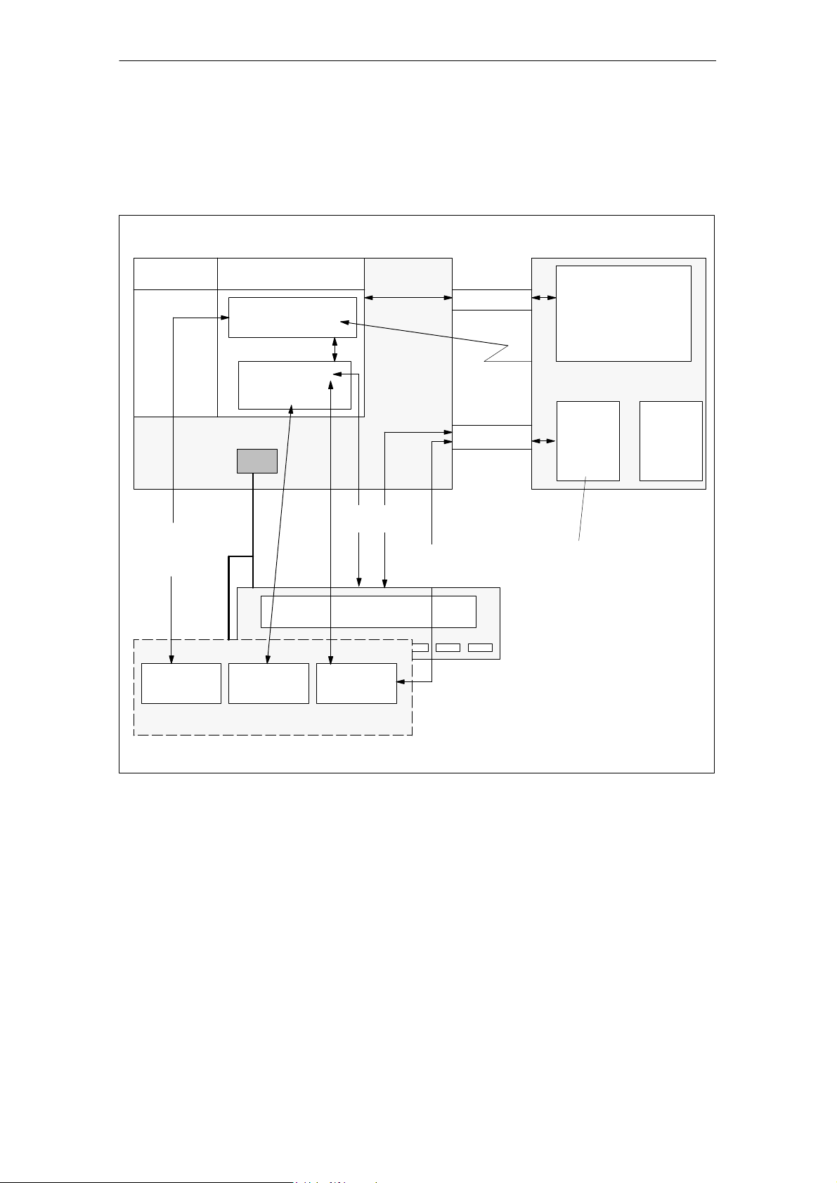
System overview of data handling
The following figure gives you an overview of the data storage concept.
FM 353CPU
Loading buffer
Operating system
Creation of the
user program
LAD/STL
Editor
RAM
User program,
including blocks
User DBx
Online data
MPI
DB Editor Parameter-
ize FM 353
Module data
Human-machine
interface
P bus
Diagnostic/
process
interrupt
K bus
Parameterization,
testing and diagnostics
OP
S Module data
S Diagnostic data
−
DBx
parameterization
data
DBx
parameterization
data
e.g.:
S Machine data
S Increments
S Tool offset data
S Traversing programs
S Status messages
PG (STEP 7)
Fig. 1-3 Data storage concept
1-6
FM 353 Stepper Drive Positioning Module
6ES7 353-1AH01-8BG0

1.2 Module description
View of the FM 353
Figure 1-4 shows the FM 353 module, its interfaces and front-panel elements (including fault and status displays).
Product Overview
Module name plate:
FM 353
FM STEPPER MOTOR
Front door
(flips open)
Status and
error displays
Drive port X2
Labeling plate
Front view with doors removed
STEP.CONTR.X2
SF
DC5V
DIAG
1
1
1
1
1
1
1
1
1
1
200
1
2
3
I0
4
I1
5
I2
6
I3
7
8
9
RM
1
Q0
2
Q1
Q2
3
Q3
4
5
6
7
8
9
DIN rail
Bus connector
SIMATIC port
Front connector
Display for digital I/O
modules
Fig. 1-4 View of the FM353
FM 353 Stepper Drive Positioning Module
6ES7 353-1AH01-8BG0
I/O port X1
1-7

Product Overview
Ports
A description of the ports is provided in Table 1-2.
Table 1-2 Ports
Bus connector −
SIMATIC port
Drive port 15-pin male sub-D connector (X2) to connect the drive unit
I/O port 20-pin male front connector (X1) to connect the load power
LED indicators
Twelve LEDs are arranged on the front panel of the FM 353. Table 1-3 describes
these LEDs and what they mean.
Table 1-3 Status and error displays
SF (red) Group error
5 V DC (green) Logic power supply is
ON
DIAG (yellow) Diagnostics
Ports
LED
Description
Back connector to continue the S7 LAN from module to module
supply and for digital input and output wiring
Significance
This LED indicates an error condition in the FM 353.
(see Troubleshooting, Chapter 11)
This LED indicates that the hardware is ready for operation.
This LED indicates various diagnostic states
(see Troubleshooting, Chapter 11)
I0 − I3 (green) Digital inputs
Q0 − Q3 (green) Digital outputs
RM (green) Input, controller message
These LEDs indicate which input is ON.
These LEDs indicate which output is ON.
This LED indicates that the input is activated.
(see Section 4.4)
1-8
FM 353 Stepper Drive Positioning Module
6ES7 353-1AH01-8BG0
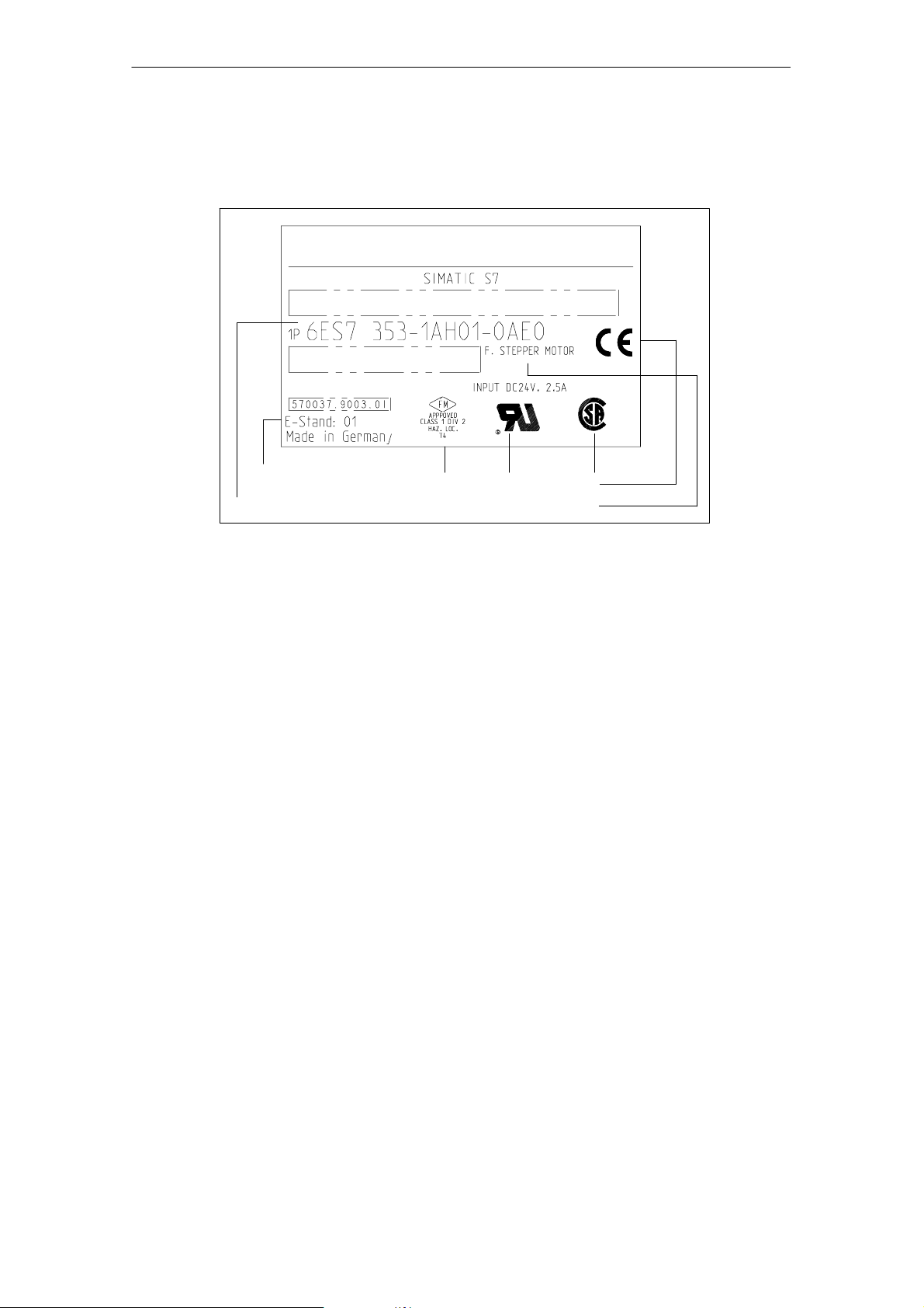
Type plate of the FM 353
Figure 1-5 describes all the information contained in the type plate of the FM 353.
SVP JM123456
Made in Germany
Product Overview
SIEMENS
Product status
Order number
Fig. 1-5 Type plate of the FM 353
Marks and approvals
Module identifier
1.3 Overview of module functions
Summary
The FM 353 module performs the following functions:
S Mode control
S Determining position
S Stepper motor control
S Digital inputs and outputs
S Settings and functions that do not depend on operating mode
S Software limit switches
S Process interrupts
S Block sequence control
S Diagnostics and troubleshooting
S Data storage on the FM 353
FM 353 Stepper Drive Positioning Module
6ES7 353-1AH01-8BG0
1-9

Product Overview
Mode control
The operating mode is specified to the FM 353 by way of the user program.
The FM 353 has the following modes available:
S Jogging
S Open-loop control
S Reference point approach
S Incremental mode, relative
S MDI-M
S Automatic
S Automatic single block
anual Data Input)
Determining position
The control frequency pulses emitted by the FM 353 are added internally to form a
position actual value.
Stepper motor control
The stepper motor control performs the following tasks:
S Guidance of the drive commensurate with speed during movement sequence
(e.g. adjustable acceleration and delay, start/stop operation)
S Output of step pulses in form of control frequency
S Output of a direction signal
S Accurate approach by axis into programmed target position
S Phase current control to the drive device
Digital inputs/outputs
Four digital inputs and four outputs can be used as specified by the user.
You might connect:
S Reference-point switches
S Switches for external starting
S Touch probes
S Position reached, Stop (“PEH”)
S Forward/backward rotation
The switching function is assigned to a given I/O number by way of the machine
data.
1-10
FM 353 Stepper Drive Positioning Module
6ES7 353-1AH01-8BG0

Settings and functions not dependent on operating mode
Special functions can be activated by specific settings in the user program, in addition to the mode (e.g., inprocess measurement).
Software limit switches
The operating range (specified by software limit switches) is automatically monitored after synchronization is recorded.
Process interrupts
Process interrupts are triggered by such events as:
S Position reached
S Length measurement completed
S On-the-fly block change
S Inprocess measurement
Product Overview
Process interrupts are selected by way of machine data.
Block sequence control
Automatic processing of a traversing program, including subprograms created during the parameterization process. A number of traversing programs are available
for execution on the module.
Diagnostics and troubleshooting
Startup and ongoing operation of the module are monitored by fault and diagnostic
interrupts. Faults or errors are reported to the system and displayed by the LEDs
on the module.
Data storage on the FM 353
Parameterization data (machine data, tool compensation data, traversing programs
and increment sizes) is retained in storage on the FM 353.
J
FM 353 Stepper Drive Positioning Module
6ES7 353-1AH01-8BG0
1-11

Product Overview
1-12
FM 353 Stepper Drive Positioning Module
6ES7 353-1AH01-8BG0
Basic Principles of Positioning
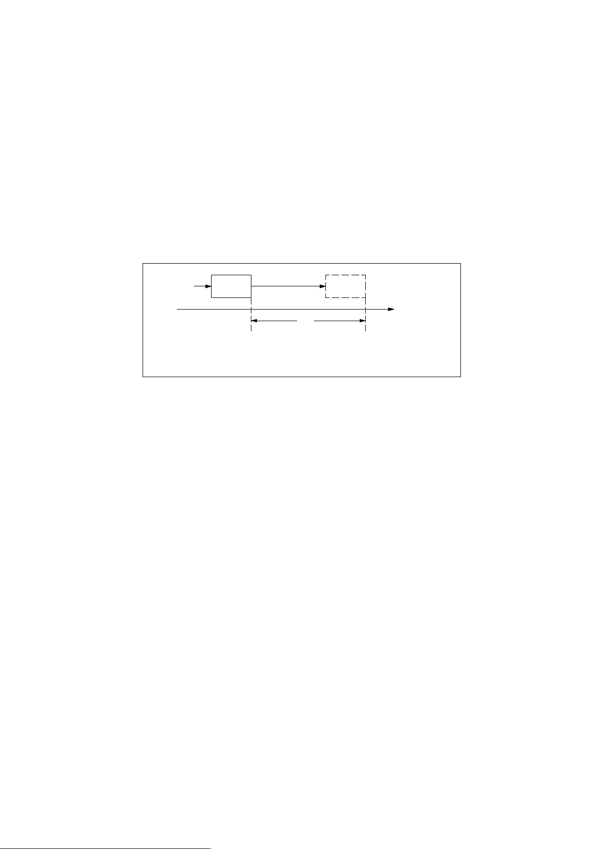
What is positioning?
Positioning means moving a load to a defined position within a defined time, taking
all influencing forces and torques into account.
F
Dx
Position A Position B
Fig. 2-1 Principle of a positioning action
What is servo-controlled positioning?
2
s
s = pathDx = distance to be traversedF = driving force
Servo-controlled positioning with a stepper motor is:
S Control of the drive at the right speed while a movement is being performed.
S Specifying a target position and true-to-target axis approach into programmed
target position
FM 353 Stepper Drive Positioning Module
6ES7 353-1AH01-8BG0
2-1
Basic Principles of Positioning
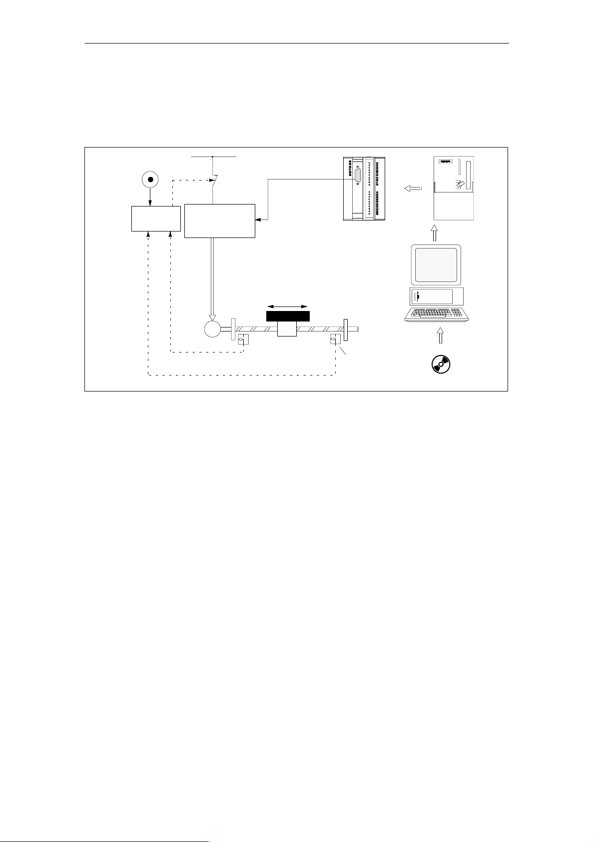
Structure of a positioning circuit
Figure 2-2 show the structure of a position control circuit with FM 353 and stepper
motor.
EMERG. STOP
Safety device
Fig. 2-2 Setup of positioning with stepper motor (example)
Power section
Motor
M
Power grid
Drive port
Movement
Mechanical transmission elements
Parameterize
Safety device
FM 353
“Parameterize FM 353”
CPU
PG
FM 353
The FM 353 generates the following for the power section:
S Control frequency
S Direction signal
S Special control signals
Power section
The power section processes the control signals and supplies power to the motor.
Motor
The motor is connected, either directly or by way of mechanical transmission elements, to the machine component to be moved.
2-2
FM 353 Stepper Drive Positioning Module
6ES7 353-1AH01-8BG0

Mechanical transmission elements
These include not only the axis, but also gear trains and clutch systems.
Peripherals
All other additional equipment is covered by the term peripherals.
Peripherals mainly include:
S Limit switches to limit the positioning range (safety devices).
S A programming device (PG) and the “Parameterize FM 353” parameterization
software.
Basic Principles of Positioning
J
FM 353 Stepper Drive Positioning Module
6ES7 353-1AH01-8BG0
2-3

Basic Principles of Positioning
2-4
FM 353 Stepper Drive Positioning Module
6ES7 353-1AH01-8BG0

Installing and Removing
Chapter Overview
Section Section Header Page
3.1 Installing the FM 353 3-3
3.2 Removing the FM 353 3-4
3.3 Replacing modules 3-5
Overview
The FM 353 is intended for installation as an I/O module in the SIMATIC S7-300
programmable logic controller.
Important safety rules
There are important rules which you must follow when integrating an FM 353 in the
S7-300 PLC in a plant or system.
3
These rules and specifications are described in the installation manual S7-300 Programmable Controller, Hardware and Installation.
Mechanical set-up
The options for the mechanical set-up and its configuration are described in the
manual S7-300 Programmable Controller; Hardware and Installation.
Below, we give only a few supplementary pointers.
Installation position
The module should preferably be installed horizontally.
In vertical installations, please observe the ambient temperature restrictions
(max. 40 °C).
FM 353 Stepper Drive Positioning Module
6ES7 353-1AH01-8BG0
3-1

Installing and Removing
What you should know about the mechanical layout
The FM 353 can be mounted in any of the eight available slots (slot nos.: 4...11) for
I/O modules on the mounting rail.
In configuring the mechanical layout of your controller, you should note the following rules:
1. No more than eight SMs or FMs per tier (rack).
2. The maximum number of modules is limited by module width and by the length
of your DIN rail.
The FM 353 requires an installation width of 80 mm (3.12 inches).
3. The maximum number of modules is limited by the total power that all modules
to the left of the CPU or IM, as the case may be, consume from the 5 V backplane bus.
The CPU 314, for example, can supply a maximum of 1.2 A.
The FM 353 requires 100 mA of this amount.
3-2
FM 353 Stepper Drive Positioning Module
6ES7 353-1AH01-8BG0

3.1 Installing the FM 353
Rules
No particular protective measures (EGB Guidelines) are necessary for the installation of the FM 353.
Warning
!
Tools required
Install the FM 353 only after all power to the S7-300 has been turned OFF.
A 4.5 mm (.18 inch) screwdriver.
Installing and Removing
Procedure
To install the FM 353:
1. The FM 353 comes with a bus connector. Plug this into the bus plug of the
module to the left of the FM 353. (The bus plug is on the back; you may have to
loosen the module already in place.)
If further modules are to be mounted to the right, plug the bus connector of the
next module into the right backplane bus connector on the FM 353.
If the FM 353 is the last module in the rack, do not connect this bus connector.
2. Hook the FM 353 onto the rail and swing it down into position.
3. Screw the FM 353 down (torque approx. 80-110 Nm).
4. After the modules have been mounted, you can also assign each of them a slot
number. Slot labels for this purpose are enclosed with the CPU.
The numbering scheme and how to plug in the slot labels are described in the
installation manual S7-300 Programmable Controller, Hardware and Installation,
for the numbering scheme to follow and how to apply the slot labels.
Note
The slot determines the initial address of each module. To find out how to allocate
the module start address, please refer to the installation manual S7-300 Program-
mable Controller, Hardware and Installation, Order No.: 6ES7 030-0AA01-8AA0.
The FM 353 is addressed in the same way as an analog module.
FM 353 Stepper Drive Positioning Module
6ES7 353-1AH01-8BG0
3-3

Installing and Removing
3.2 Removing the FM 353
Rules
No particular protective measures (EGB Guidelines) are necessary for the removal
of the FM 353.
Warning
!
Tools required
Remove the FM 353 only after all power to the S7-300 has been turned OFF.
A 4.5 mm (.18 inch) screwdriver.
Procedure
To remove the FM 353:
1. Open the front doors. If necessary, remove the labeling strips.
2. Detach the power-supply connections from the terminal block.
3. Detach the sub-D plug from the drive unit.
4. Release the protective device on the front connector and unplug it.
5. Loosen the fastening screws and swing the module up and out.
3-4
FM 353 Stepper Drive Positioning Module
6ES7 353-1AH01-8BG0
 Loading...