

Siemens SIMATIC FM 351 User Manual

Preface, Contents
User Information
SIMATIC
FM 351 Positioning Module
Manual
This manual is part of the documentation package
with the order number:
6ES7351-1AH00-8BG0
Product Overview
Basics of Positioning
Installing and Removing the
FM 351
Wiring the FM 351
Installing the Configuration
Package
Programming the FM 351
Putting the FM 351 into Operation
Reference Information
Machine Data and Increments
Modes and Jobs
1
2
3
4
5
6
7
8
9
03/2000
C79000-G7076-C351
Edition 02
Encoders
Diagnostics
Samples
Appendix
Technical Specifications
Connection Diagrams
Data Blocks, Error Classes
Index
10
11
12
A
B
C

Notes on Safety
Danger
!
indicates that death, severe personal injury or substantial property damage will result if proper precautions are
not taken.
Warning
!
indicates that death, severe personal injury or substantial property damage can result if proper precautions are
not taken.
Caution
!
indicates that minor personal injury or property damage can result if proper precautions are not taken.
Note
draws your attention to particularly important information on the product, handling the product, or to a particular
part of the documentation.
Qualified Personnel
Only qualified personnel should be allowed to install and work on this equipment. Qualified persons are defined as persons who are authorized to commission, to ground, and to tag circuits, equipment, and systems in
accordance with established safety practices and standards.
Correct Usage
Note the following:
Warning
!
Trademarks
The reproduction, transmission or use of this document or its contents is not
permitted without express written authority. Offenders will be liable for
damages. All rights, including rights created by patent grant or registration of
a utility model or design, are reserved.
This device and its components may only be used for the applications described in the catalog or the technical
description, and only in connection with devices or components from other manufacturers which have been
approved or recommended by Siemens.
This product can only function correctly and safely if it is transported, stored, set up, and installed correctly,
and operated and maintained as recommended.
SIMATIC, SIMATIC HMI and SIMATIC NET are registered trademarks of SIEMENS AG.
Third parties using for their own purposes any other names in this document which refer to trademarks might
infringe upon the rights of the trademark owners.
Disclaimer of LiabilityCopyright Siemens AG 1996 All rights reserved
We have checked the contents of this manual for agreement with the hardware and software described. Since deviations cannot be precluded entirely,
we cannot guarantee full agreement. However, the data in this manual are
reviewed regularly and any necessary corrections included in subsequent
editions. Suggestions for improvement are welcomed.
Siemens AG
Bereich Automatisierungs- und Antriebstechnik
Geschäftsgebiet Industrie-Automatisierungssysteme
Postfach 4848, D- 90327 Nürnberg
Siemens Aktiengesellschaft C79000-G7076-C351
Siemens AG 1996
Subject to technical change.
Preface
Validity of the Manual
This manual contains the description of the FM 351 positioning module valid at the
time of publication. We reserve the right to describe modifications in the
functionality of the FM 351 in a product information bulletin.
The manual with the
number in the footer ....
EWA 4NEB 720 6001-02
C79000-G7000-C351-02 6ES7 351-1AH01-0AE0
Order number Revision level
6ES7 351-1AH00-0AE0
6ES7 351-1AH01-0AE0
Content of the Manual
This manual describes the hardware and software of the FM 351 positioning
module.
It consists of the following:
• A section describing basic aspects (Chapters 1 to 7)
• A reference section (Chapters 8 to 12)
• An appendix (Chapters A, B and C)
• An index.
... is valid for the FM 351
1 =
3 =
2
43
4
65
2 =
3
54
FM 351 Positioning Module
C79000-G7076-C351-02
iii

Preface
CE Mark
Our products meet the requirements of the EU directive 89/336/EEC
”Electromagnetic Compatibility” and the harmonized European standards (EN)
listed in the directive.
In compliance with the above mentioned EU directive, Article 10, the conformity
declarations are available to the relevant authorities at the following address:
Further Support
If you have questions about using the products described in the manual and you
cannot find the answers here, please contact your local Siemens representative.
You will find the addresses, for example, in the appendix ”SIEMENS Worldwide” in
the manual:
S7-300 Programmable Controller, Installation.
Siemens Aktiengesellschaft
Bereich Automatisierungstechnik
A&D AS E 48
Postfach 1963
D-92209 Amberg
If you have any questions or comments on this manual, please fill out the remarks
form at the end of the manual and return it to the address shown on the form. We
would be grateful if you could take the time to answer the questions giving your
own personal opinion of the manual.
To help you to become familiar with working with SIMATIC S7 PLCs, we offer a
range of courses. Please contact your regional training center or the central
training center in D-90027 Nuremberg, Tel. +49 911/895-3202 for more information.
Up to the Minute Information
You can obtain the latest information on SIMATIC products from the following
sources:
•on the Internet at
SIMATIC Customer Support also provides you with the latest information and
downloads that will help you use SIMATIC products:
•on the Internet at
•From the SIMATIC Customer Support Mailbox at the number +49 (911)
895-7100
To dial the mailbox, use a modem with up to V.34
(28.8 kbauds), with the following parameter settings:
8, N, 1, ANSI, or dial via ISDN (x.75, 64 Kbps).
http://www.ad.siemens.de/
http://www.ad.siemens.de/simatic–cs
SIMATIC Customer Support is available at the phone and fax numbers and at the
E–mail addresses listed below. You can also contact us via Internet mail or mail at
the mailbox mentioned above.
FM 351 Positioning Module
iv
C79000-G7076-C351-02

Johnson City
Preface
Nuremberg
Singapore
Simatic Basic Hotline
Nuremberg
SIMATIC BASIC Hotline
Local time: Mo.-Fr. 8:00 to 18:00
Phone: +49 (911) 895-7000
Fax: +49 (911) 895-7002
E-mail: simatic.support@
nbgm.siemens.de
Johnson City
SIMATIC BASIC Hotline
Local time: Mo.-Fr. 8:00 to 17:00
Phone: +1 423 461-2522
Fax: +1 423 461-2231
E-mail: simatic.hotline@
sea.siemens.com
Singapore
SIMATIC BASIC Hotline
Local time: Mo.-Fr. 8:30 to 17:30
Phone: +65 740-7000
Fax: +65 740-7001
E-mail: simatic@
sae.siemens.com.sg
SIMATIC Premium Hotline
(Calls charged, only with
SIMATIC Card)
Time: Mo.-Fr. 0:00 to 24:00
Phone: +49 (911) 895-7777
Fax: +49 (911) 895-7001
The languages spoken on the hotlines are generally German and English. On the
authorization hotline, French, Italian and Spanish are also available.
FM 351 Positioning Module
C79000-G7076-C351-02
v

Preface
FM 351 Positioning Module
vi
C79000-G7076-C351-02

Contents
1 Product Overview 1-1. . . . . . . . . . . . . . . . . . . . . . . . . . . . . . . . . . . . . . . . . . . . . . . . . . . . . .
1.1 What is the FM 351? 1-2. . . . . . . . . . . . . . . . . . . . . . . . . . . . . . . . . . . . . . . . . . . . .
1.2 Areas of Application of the FM 351 1-3. . . . . . . . . . . . . . . . . . . . . . . . . . . . . . . .
1.3 Setup for Controlled Positioning with an FM 351 1-4. . . . . . . . . . . . . . . . . . . . .
2 Basics of Positioning 2-1. . . . . . . . . . . . . . . . . . . . . . . . . . . . . . . . . . . . . . . . . . . . . . . . . . .
2.1 Controlled Positioning 2-2. . . . . . . . . . . . . . . . . . . . . . . . . . . . . . . . . . . . . . . . . . . .
2.2 Ranges and Switching Points of the FM 351 2-2. . . . . . . . . . . . . . . . . . . . . . . .
3 Installing and Removing the FM 351 3-1. . . . . . . . . . . . . . . . . . . . . . . . . . . . . . . . . . . . .
4 Wiring the FM 351 4-1. . . . . . . . . . . . . . . . . . . . . . . . . . . . . . . . . . . . . . . . . . . . . . . . . . . . . .
4.1 Description of the Encoder Interface 4-2. . . . . . . . . . . . . . . . . . . . . . . . . . . . . . .
4.2 Connecting the Encoders 4-3. . . . . . . . . . . . . . . . . . . . . . . . . . . . . . . . . . . . . . . . .
4.3 Description of the Front Connector 4-4. . . . . . . . . . . . . . . . . . . . . . . . . . . . . . . . .
4.4 Wiring the Power Unit 4-7. . . . . . . . . . . . . . . . . . . . . . . . . . . . . . . . . . . . . . . . . . . .
4.5 Wiring the Front Connector 4-9. . . . . . . . . . . . . . . . . . . . . . . . . . . . . . . . . . . . . . .
5 Installing the Configuration Package 5-1. . . . . . . . . . . . . . . . . . . . . . . . . . . . . . . . . . . . .
6 Programming the FM 351 6-1. . . . . . . . . . . . . . . . . . . . . . . . . . . . . . . . . . . . . . . . . . . . . . .
6.1 Basics of Programming an FM 351 6-2. . . . . . . . . . . . . . . . . . . . . . . . . . . . . . . .
6.2 FC ABS_INIT (FC0) 6-4. . . . . . . . . . . . . . . . . . . . . . . . . . . . . . . . . . . . . . . . . . . . .
6.3 FC ABS_CTRL (FC1) 6-5. . . . . . . . . . . . . . . . . . . . . . . . . . . . . . . . . . . . . . . . . . . .
6.4 FC ABS_DIAG (FC2) 6-11. . . . . . . . . . . . . . . . . . . . . . . . . . . . . . . . . . . . . . . . . . . .
6.5 Data Blocks 6-13. . . . . . . . . . . . . . . . . . . . . . . . . . . . . . . . . . . . . . . . . . . . . . . . . . . .
6.5.1 Templates for Data Blocks 6-13. . . . . . . . . . . . . . . . . . . . . . . . . . . . . . . . . . . . . . . .
6.5.2 Channel DB 6-13. . . . . . . . . . . . . . . . . . . . . . . . . . . . . . . . . . . . . . . . . . . . . . . . . . . .
6.5.3 Diagnostic DB 6-14. . . . . . . . . . . . . . . . . . . . . . . . . . . . . . . . . . . . . . . . . . . . . . . . . .
6.5.4 Parameter DB 6-14. . . . . . . . . . . . . . . . . . . . . . . . . . . . . . . . . . . . . . . . . . . . . . . . . .
6.6 Technical Specifications of the FCs and DBs for the FM 351 6-15. . . . . . . . . .
6.7 Fast Access to Module Data 6-17. . . . . . . . . . . . . . . . . . . . . . . . . . . . . . . . . . . . .
6.8 Parameter Transfer Routes 6-19. . . . . . . . . . . . . . . . . . . . . . . . . . . . . . . . . . . . . .
FM 351 Positioning Module
C79000-G7076-C351-02
vii

Contents
7 Putting the FM 351 into Operation 7-1. . . . . . . . . . . . . . . . . . . . . . . . . . . . . . . . . . . . . . .
8 Machine Data and Incremental Dimensions 8-1. . . . . . . . . . . . . . . . . . . . . . . . . . . . . . .
8.1 Writing and Reading Machine Data and Incremental
Dimension Tables 8-2. . . . . . . . . . . . . . . . . . . . . . . . . . . . . . . . . . . . . . . . . . . . . . .
8.2 System of Units 8-5. . . . . . . . . . . . . . . . . . . . . . . . . . . . . . . . . . . . . . . . . . . . . . . .
8.3 Machine Data for the Drive 8-6. . . . . . . . . . . . . . . . . . . . . . . . . . . . . . . . . . . . . . .
8.4 Machine Data for the Axis 8-12. . . . . . . . . . . . . . . . . . . . . . . . . . . . . . . . . . . . . . . .
8.5 Machine Data for the Encoder 8-15. . . . . . . . . . . . . . . . . . . . . . . . . . . . . . . . . . . .
8.6 Absolute Encoder Adjustment 8-19. . . . . . . . . . . . . . . . . . . . . . . . . . . . . . . . . . . . .
8.7 Resolution 8-22. . . . . . . . . . . . . . . . . . . . . . . . . . . . . . . . . . . . . . . . . . . . . . . . . . . . . .
8.8 Incremental dimensions 8-24. . . . . . . . . . . . . . . . . . . . . . . . . . . . . . . . . . . . . . . . . .
8.8.1 Incremental dimension number 1 to 100 8-24. . . . . . . . . . . . . . . . . . . . . . . . . . . .
8.8.2 Incremental Dimension Number 254 8-25. . . . . . . . . . . . . . . . . . . . . . . . . . . . . . .
8.8.3 Incremental Dimension Number 255 8-26. . . . . . . . . . . . . . . . . . . . . . . . . . . . . . .
9 Modes and Jobs 9-1. . . . . . . . . . . . . . . . . . . . . . . . . . . . . . . . . . . . . . . . . . . . . . . . . . . . . . . .
9.1 End of Positioning 9-2. . . . . . . . . . . . . . . . . . . . . . . . . . . . . . . . . . . . . . . . . . . . . . .
9.2 Jogging Operating Mode 9-8. . . . . . . . . . . . . . . . . . . . . . . . . . . . . . . . . . . . . . . . .
9.3 Reference Point Approach Mode 9-11. . . . . . . . . . . . . . . . . . . . . . . . . . . . . . . . . .
9.4 Incremental Operating Mode 9-17. . . . . . . . . . . . . . . . . . . . . . . . . . . . . . . . . . . . . .
9.5 Set Actual Value / Cancel Set Actual Value 9-23. . . . . . . . . . . . . . . . . . . . . . . . .
9.6 Set Reference Point 9-25. . . . . . . . . . . . . . . . . . . . . . . . . . . . . . . . . . . . . . . . . . . . .
9.7 Loop Traverse 9-27. . . . . . . . . . . . . . . . . . . . . . . . . . . . . . . . . . . . . . . . . . . . . . . . . .
9.8 Enable input 9-30. . . . . . . . . . . . . . . . . . . . . . . . . . . . . . . . . . . . . . . . . . . . . . . . . . . .
9.9 Read Position Data 9-31. . . . . . . . . . . . . . . . . . . . . . . . . . . . . . . . . . . . . . . . . . . . . .
9.10 Read Encoder Data 9-32. . . . . . . . . . . . . . . . . . . . . . . . . . . . . . . . . . . . . . . . . . . . . .
9.11 Return Signals for Positioning 9-33. . . . . . . . . . . . . . . . . . . . . . . . . . . . . . . . . . . . .
9.12 Return Signals for Diagnostics 9-34. . . . . . . . . . . . . . . . . . . . . . . . . . . . . . . . . . . .
10 Encoders 10-1. . . . . . . . . . . . . . . . . . . . . . . . . . . . . . . . . . . . . . . . . . . . . . . . . . . . . . . . . . . . . .
10.1 Incremental Encoders 10-2. . . . . . . . . . . . . . . . . . . . . . . . . . . . . . . . . . . . . . . . . . .
10.2 Absolute Encoders 10-4. . . . . . . . . . . . . . . . . . . . . . . . . . . . . . . . . . . . . . . . . . . . . .
11 Diagnostics 11-1. . . . . . . . . . . . . . . . . . . . . . . . . . . . . . . . . . . . . . . . . . . . . . . . . . . . . . . . . . . .
11.1 Options for Displaying and Evaluating Errors 11-2. . . . . . . . . . . . . . . . . . . . . . . .
11.2 Types of Error 11-2. . . . . . . . . . . . . . . . . . . . . . . . . . . . . . . . . . . . . . . . . . . . . . . . . .
11.2.1 Synchronous Errors 11-2. . . . . . . . . . . . . . . . . . . . . . . . . . . . . . . . . . . . . . . . . . . . .
11.2.2 Asynchronous Errors 11-2. . . . . . . . . . . . . . . . . . . . . . . . . . . . . . . . . . . . . . . . . . . .
11.3 Meaning of the Error LEDs 11-3. . . . . . . . . . . . . . . . . . . . . . . . . . . . . . . . . . . . . . .
11.4 Displaying Errors on an OP 11-4. . . . . . . . . . . . . . . . . . . . . . . . . . . . . . . . . . . . . . .
viii
FM 351 Positioning Module
C79000-G7076-C351-02

Contents
11.5 Error Evaluation in the User Program 11-5. . . . . . . . . . . . . . . . . . . . . . . . . . . . . .
11.6 Diagnostic Buffer of the Module 11-10. . . . . . . . . . . . . . . . . . . . . . . . . . . . . . . . . . .
11.7 Diagnostic Interrupts 11-11. . . . . . . . . . . . . . . . . . . . . . . . . . . . . . . . . . . . . . . . . . . . .
12 Samples 12-1. . . . . . . . . . . . . . . . . . . . . . . . . . . . . . . . . . . . . . . . . . . . . . . . . . . . . . . . . . . . . . .
12.1 Introduction 12-2. . . . . . . . . . . . . . . . . . . . . . . . . . . . . . . . . . . . . . . . . . . . . . . . . . . . .
12.2 Requirements 12-2. . . . . . . . . . . . . . . . . . . . . . . . . . . . . . . . . . . . . . . . . . . . . . . . . . .
12.3 Preparing the Samples 12-3. . . . . . . . . . . . . . . . . . . . . . . . . . . . . . . . . . . . . . . . . . .
12.4 Code of the Samples 12-3. . . . . . . . . . . . . . . . . . . . . . . . . . . . . . . . . . . . . . . . . . . .
12.5 Testing a Sample 12-4. . . . . . . . . . . . . . . . . . . . . . . . . . . . . . . . . . . . . . . . . . . . . . . .
12.6 Adapting a Sample 12-4. . . . . . . . . . . . . . . . . . . . . . . . . . . . . . . . . . . . . . . . . . . . . .
12.7 Sample Program 1 “GettingStarted” 12-5. . . . . . . . . . . . . . . . . . . . . . . . . . . . . . . .
12.8 Sample Program 2 “Commission” 12-7. . . . . . . . . . . . . . . . . . . . . . . . . . . . . . . . . .
12.9 Sample Program 3 “AllFunctions” 12-9. . . . . . . . . . . . . . . . . . . . . . . . . . . . . . . . . .
12.10 Sample Program 4 “OneChannel” 12-11. . . . . . . . . . . . . . . . . . . . . . . . . . . . . . . . .
12.11 Sample Program 5 “DiagnosticAndInterrupt” 12-14. . . . . . . . . . . . . . . . . . . . . . . .
12.12 Sample Program 6 “MultiChannels” 12-16. . . . . . . . . . . . . . . . . . . . . . . . . . . . . . . .
A Technical Specifications A-1. . . . . . . . . . . . . . . . . . . . . . . . . . . . . . . . . . . . . . . . . . . . . . . .
B Connection Diagrams B-1. . . . . . . . . . . . . . . . . . . . . . . . . . . . . . . . . . . . . . . . . . . . . . . . . . .
B.1 Connection Diagram for Incremental Encoder Siemens 6FX 2001-2
(Up=5V; RS 422) B-2. . . . . . . . . . . . . . . . . . . . . . . . . . . . . . . . . . . . . . . . . . . . . . . .
B.2 Connection Diagram for Incremental Encoder Siemens 6FX 2001-2
(Up=24V; RS 422) B-3. . . . . . . . . . . . . . . . . . . . . . . . . . . . . . . . . . . . . . . . . . . . . . .
B.3 Connection Diagram for Incremental Encoder Siemens 6FX 2001-4
(Up=24V; HTL) B-4. . . . . . . . . . . . . . . . . . . . . . . . . . . . . . . . . . . . . . . . . . . . . . . . .
B.4 Connection Diagram for Absolute Encoder Siemens 6FX 2001-5
(Up=24V; SSI) B-5. . . . . . . . . . . . . . . . . . . . . . . . . . . . . . . . . . . . . . . . . . . . . . . . . .
C Data Blocks/Error Lists C-1. . . . . . . . . . . . . . . . . . . . . . . . . . . . . . . . . . . . . . . . . . . . . . . . .
C.1 Content of the Channel DB C-2. . . . . . . . . . . . . . . . . . . . . . . . . . . . . . . . . . . . . . .
C.2 Content of the Parameter DB C-9. . . . . . . . . . . . . . . . . . . . . . . . . . . . . . . . . . . . .
C.3 Data and Structure of the Diagnostic DB C-11. . . . . . . . . . . . . . . . . . . . . . . . . . . .
C.4 List of JOB_ERR Messages C-13. . . . . . . . . . . . . . . . . . . . . . . . . . . . . . . . . . . . . .
C.5 Error Classes C-15. . . . . . . . . . . . . . . . . . . . . . . . . . . . . . . . . . . . . . . . . . . . . . . . . . .
Index Index-1. . . . . . . . . . . . . . . . . . . . . . . . . . . . . . . . . . . . . . . . . . . . . . . . . . . . . . . . . . . . . . . .
FM 351 Positioning Module
C79000-G7076-C351-02
ix

Contents
FM 351 Positioning Module
x
C79000-G7076-C351-02

Product Overview
Chapter Overview
Section Topic Page
1.1 What is the FM 351? 1-2
1.2 Areas of Application of the FM 351 1-3
1.3 Setup for Controlled Positioning with an FM 351 1-4
1
FM 351 Positioning Module
C79000-G7076-C351-02
1-1
Product Overview
1.1 What is the FM 351?
The FM 351 positioning module is used in the S7-300 programmable logic
controller (PLC) for controlled positioning with rapid/creep feed speeds. The
module has two independent channels each of which can control a rotary or linear
axis. Each channel of the module supports an incremental or absolute encoder
(SSI).
You can operate a number of FM 351 positioning modules simultaneously.
Combinations with other FM/CP modules are also possible. A typical application is
the combination with an FM 352 electronic cam controller.
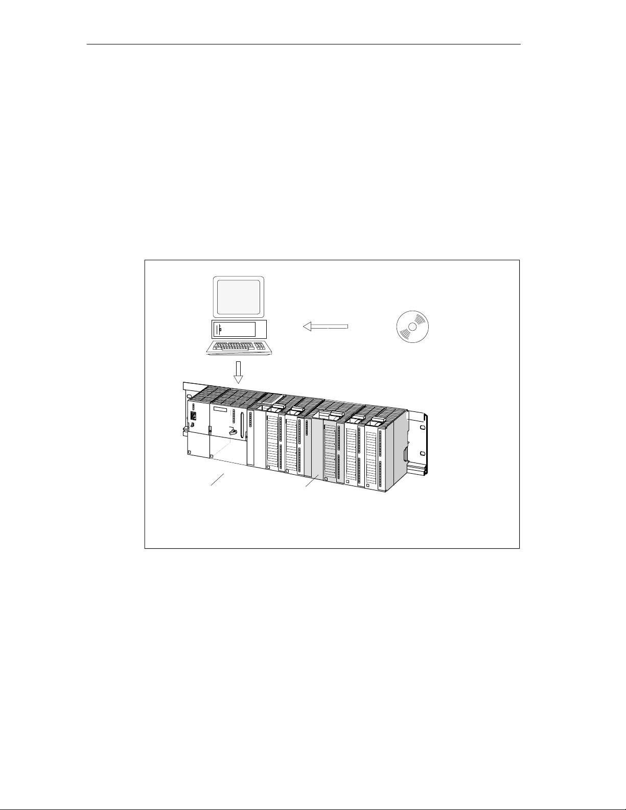
PC/PG
S7-300
CPU
with user program and
blocks for the FM 351
Figure 1-1 Structure of a SIMATIC S7-300 PLC with an FM 351
FM 351
Configuration package with
parameter assignment dialogs,
blocks and manual
1-2
FM 351 Positioning Module
C79000-G7076-C351-02

1.2 Areas of Application of the FM 351
• Packing machines
• Lifting and transport equipment
• Woodworking machines
Example: Control of feed operations
Various wooden parts are processed with a profile machine. Various operations
and cutters are required to process the wood. The various cutters are changed
by controlled positioning operations.
• Paper and printing machines
• Rubber and plastics processing machines
Example: Simple handling
The molded parts in an injection molding machine are removed from the mold
by a grab arm. The arm is controlled by the positioning module.
Product Overview
• Building materials industry
• Machine tools
FM 351 Positioning Module
C79000-G7076-C351-02
1-3
Product Overview
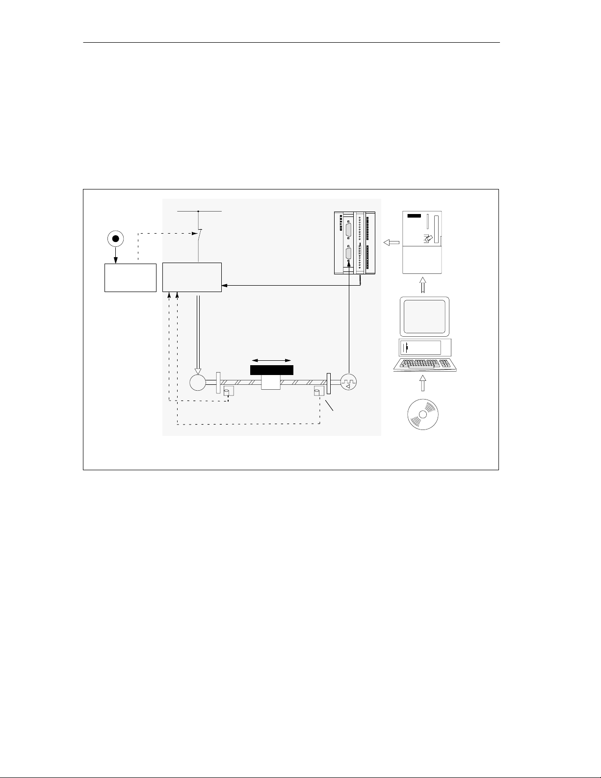
1.3 Setup for Controlled Positioning with an FM 351
Control Circuit
Figure 1-2 illustrates the components of a controlled positioning setup with
rapid/creep speed drives.
EMERGENCY
STOP switch
Safety
device
Figure 1-2 Controlled Positioning
Power supply
Power unit
Processing
stations
M
Motor
FM 351
Positioning
Module
Motion
Mechanical
transmission
elements
CPU
PC/PG
Encoders
Hardware
limit switch
Configuration package with
parameter assignment user
interface, blocks and manual
Power Unit and Safety Device
The power unit (for example a contactor combination) is activated via the digital
outputs of the FM 351. The FM 351 has four control modes (see Section 8.3, page
8-6).
If the safety device responds, (EMERGENCY OFF switch or hardware limit
switch), the power unit turns off the motor.
Motor
The motor is controlled by the power unit and drives the axis.
1-4
FM 351 Positioning Module
C79000-G7076-C351-02

Encoders
The encoder supplies information both about position and direction. The following
encoders can be connected:
• Incremental encoders with 5 V differential signals, symmetrical
• Incremental encoders with 24 V signals, asymmetrical
• SSI absolute encoders
FM 351 Positioning Module
The FM 351 can position up to two axes automatically using rapid/creep feed.
The power unit is controlled via four digital outputs (see Section 8.3, page 8-6).
The FM 351 positioning module calculates the current actual position value of the
axis from the encoder signals that are proportional to the distance moved (see
Section 8.5, page 8-15 and Section 8.7, page 8-22).
The FM 351 provides the following modes and functions:
Product Overview
CPU
PC/PG
• “Jogging” (see Section 9.2, page 9-8).
• “Reference point approach” (see Section 9.3, page 9-11).
• “Absolute/relative incremental approach” (see Section 9.4, page 9-17).
• Set actual value (see Section 9.5, page 9-23).
• Set reference point (see Section 9.6, page 9-25).
• Loop traverse (see Section 9.7, page 9-27).
The CPU executes the user program. Data and signals are exchanged between
the user program and the module using function calls.
The PC/programming device is used for the following:
• Parameter assignment: You make the parameter settings for the FM 351 either
with the
6-14).
• Programming: You program the FM 351 with functions that you incorporate
directly in your user program.
parameter dialogs
or using the parameter DB (see Section 6.5.4, page
• Testing and commissioning: You test the FM 351 and commission it using the
parameter dialogs
FM 351 Positioning Module
C79000-G7076-C351-02
.
1-5

Product Overview
Overview of the Positioning Module
• Two axes, axis types:
– linear axis
– rotary axis
• Four digital outputs per axis
• Four digital inputs per axis
• Typical drives/motors:
– Standard motor, contactor controlled
– Standard motor with frequency converter (example Micromaster)
– Asynchronous motor connected to power unit with vector control.
• Positioning systems:
– Incremental encoder 5 V, symmetrical
– Incremental encoder 24 V, asymmetrical
– SSI absolute encoders
• Monitoring functions:
– Working range monitoring with software limit switches
– Stationary state monitoring
– Encoder monitoring
– Monitoring of axis movement and final target approach
• System environment:
– Central use
SIMATIC S7-300, CPU 314 or higher (recommendation: dependent on the
application and user memory requirements)
SIMATIC C7
– Distributed use with ET 200M
• System integration:
– Module exchange without PG possible
– Teleservice possible
1-6
FM 351 Positioning Module
C79000-G7076-C351-02

Basics of Positioning
Chapter Overview
Section Topic Page
2.1 Controlled Positioning 2-2
2.2 Ranges and Switching Points of the FM 351 2-2
2
FM 351 Positioning Module
C79000-G7076-C351-02
2-1

Basics of Positioning
2.1 Controlled Positioning
Each positioning operation is characterized by the following:
• a start position
• a target to which the tool will move, and
• parameters determining how the positioning operation is executed.
The target position is first approached at high speed (rapid speed).
At a specified distance from the target position the speed is reduced to a lower
speed (creep speed). Shortly before the axis reaches the target position, again at a
specified distance from the target position, the drive is switched off. The module
then monitors the final target approach.
The drive is controlled via digital outputs that set the rapid or creep speed and the
required direction (see Section 8.3, page 8-6).
2.2 Ranges and Switching Points of the FM 351
Target
The target is the absolute or relative position on the axis that is approached during
a positioning operation.
Definition of the Switching Points and Ranges
The following ranges and positions can be set for each positioning operation:
Range Explanation
Working range Defines the range that you set for your task using the software limit
switches or the end of the rotary axis.
Switchover
difference
Switchover point Defines the position at which the drive changes from rapid speed to
Switch-off
difference
Switch-off point Defines the position at which the drive is turned off. From this point
Target range Defines the positioning accuracy of your application and is located
Stationary range Defines a symmetrical range around the target that is monitored by the
Defines the distance to the target at which the drive switches from rapid
speed to creep speed.
creep speed.
Defines the distance to the target at which the drive is turned off.
onwards, the FM 351 activates monitoring functions.
symmetrically either side of the target.
FM 351.
2-2
FM 351 Positioning Module
C79000-G7076-C351-02
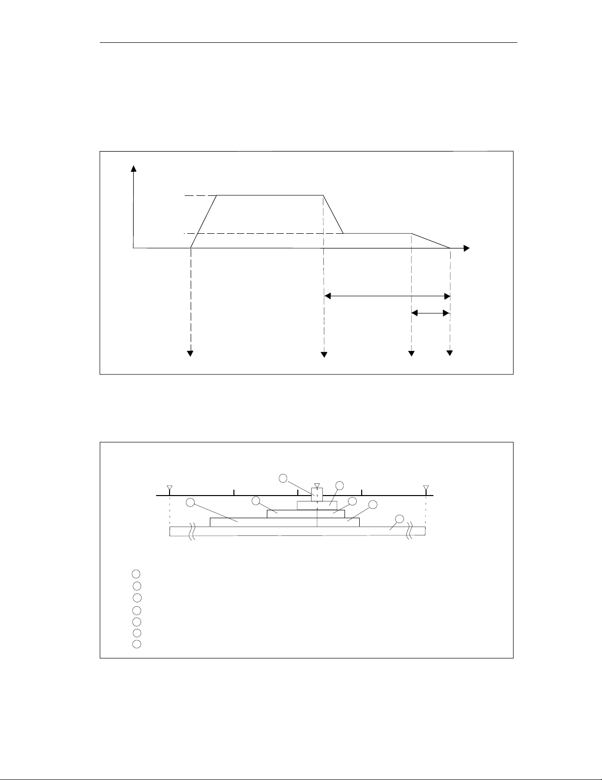
Figure 2-1 shows a possible arrangement of the switching points and differences
for a positioning operation. To simplify the illustration, it is assumed that the change
in actual speed is linear over the distance traveled. The ramps that result, are due
to mechanical inertia or due to the parameter settings for the power unit.
v
rapid
v
Actual speed
creep
Switchover
difference
Basics of Positioning
Travel
Sw-off
diff.
Start
Figure 2-1 Switching Points and Differences
Figure 2-2 illustrates how the switching ranges can be arranged around the target.
Software start limit switch
2
1
Working range
2
Switchover difference in travel direction plus
3
Switchover difference in travel direction minus
4
Switch-off di fference in travel direction plus
5
Switch-off di fference in travel direction minus
6
Stationary range
7
Target range
4
Switchover point
Target
7
0
Switch-off point
6
5
Software end limit switch
3
1
Target
Figure 2-2 Switching Ranges Around a Target
FM 351 Positioning Module
C79000-G7076-C351-02
2-3

Basics of Positioning
2-4
FM 351 Positioning Module
C79000-G7076-C351-02

Installing and Removing the FM 351
Important Safety Rules
When integrating an S7-300 with an FM 351 in a plant or system, there are
important rules and regulations that are described in the installation manual
Programmable Controller, Hardware and Installation
Installation of the Rail
Horizontal installation of the rail is preferable.
If you install the rail vertically, remember the restrictions regarding the ambient
temperature (max. 40 °C).
Selecting Slots
The FM 351 can be installed in any slot for signal modules on the rail.
Required Tools
.
3
S7-300
To install or remove the FM 351, you require a 4.5 mm screwdriver.
FM 351 Positioning Module
C79000-G7076-C351-02
3-1

Installing and Removing the FM 351
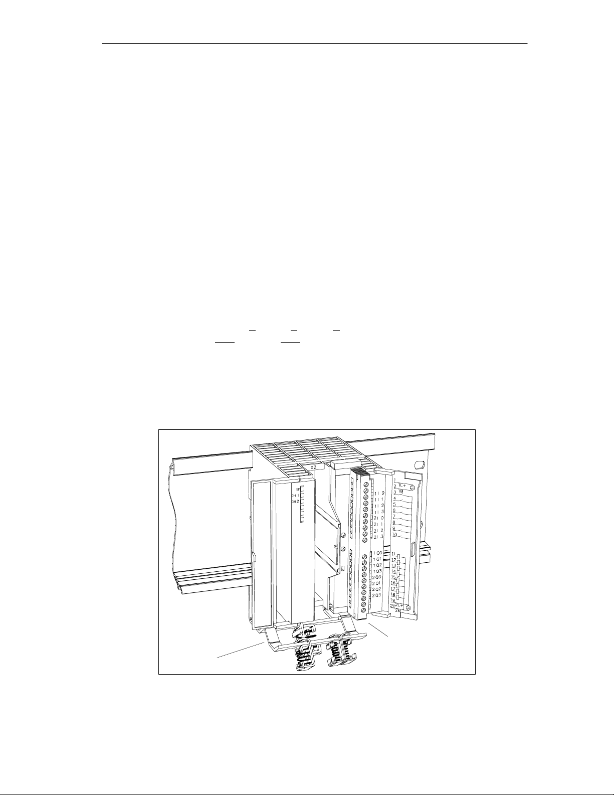
Installing the FM 351 Positioning Module
1. The FM 351 is supplied with a bus interconnector. Plug this onto the bus
connector of the module to the left of the FM 351. (The bus connector is on the
back of the module and you may need to loosen the module again first).
2. If further modules are installed to the right, first plug the bus interconnector of
the next module onto the right bus connector of the FM 351.
If the FM 351 is the last module in the tier, do not attach a bus interconnector!
3. Fit the FM 351 onto the rail from above and push it in from below.
4. Secure the FM 351 with screws (torque approximately 0.8 to 1.1 Nm).
5. After installation, you can assign a slot number to the FM 351. Slot labels are
supplied with the CPU.
The numbering scheme and numbering of slots and how to insert the slot labels
is described in the installation manual
Hardware and Installation
6. Fit the shield contact element.
.
S7-300 Programmable Controller,
Order no.: 6ES7 390-5AA00-0AA0
Removing the FM 351 Positioning Module
1. Turn off the power controller.
2. Turn off the 24 V supply for the FM 351.
3. Switch the CPU to STOP.
4. Open the front hinged panels.
Remove any labeling strips.
5. Unlock the front connector and remove it.
6. Remove the D sub connector to the encoder.
7. Loosen the securing screws on the module.
8. Tilt the module upwards and remove it from the rail.
3-2
FM 351 Positioning Module
C79000-G7076-C351-02

Wiring the FM 351
Chapter Overview
Section Topic Page
4.1 Description of the Encoder Interface 4-2
4.2 Connecting the Encoders 4-3
4.3 Description of the Front Connector 4-4
4.4 Wiring the Power Unit 4-7
4.5 Wiring the Front Connector 4-9
Important Safety Rules
It is essential for the safety of the system to install the elements listed below and to
adapt them to your system.
4
• EMERGENCY STOP switch with which you can turn off the entire system.
• Hardware limit switches that directly influence the power units of all drives.
• Motor circuit-breaker.
FM 351 Positioning Module
C79000-G7076-C351-02
4-1
Wiring the FM 351
4.1 Description of the Encoder Interface
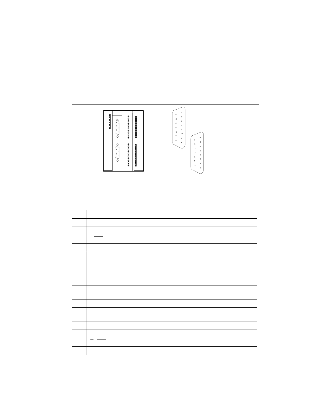
Location of the Sub-D Connectors
Figure 4-1 shows the location and labeling of the female connectors on the
module. You can connect incremental or absolute encoders (SSI) to the two sub-D
female connectors (see Section 10).
FM 351
15
9
X2 CH1
8
Channel 1
1
15
8
X3 CH2
Channel 2
Figure 4-1 Location of the Sub–D Connectors X2 and X3
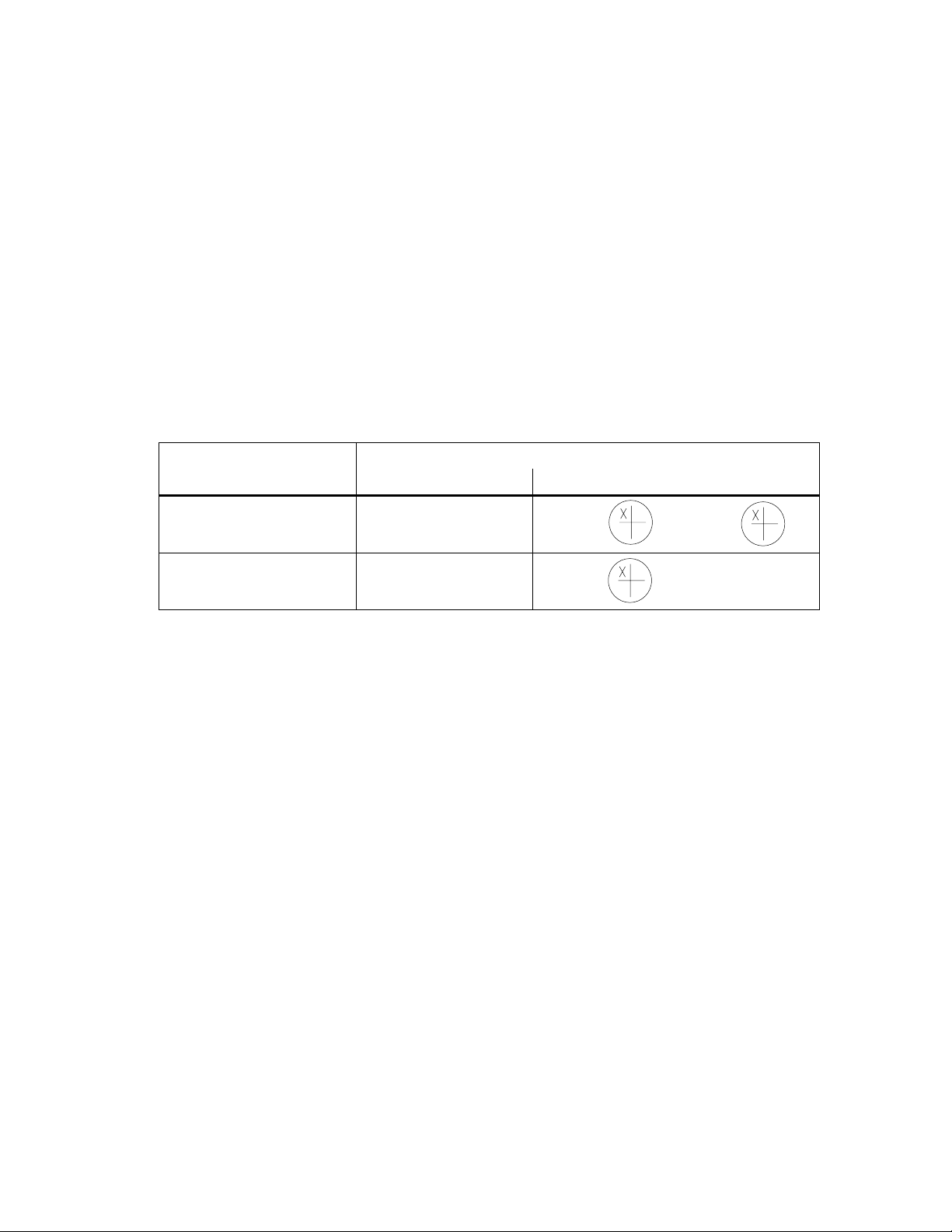
Pinout of the Female Connectors X2 and X3
Pin Name Incr. Encoder (24V) Incr. Encoder (5V) Absolute Encoders
1 A* Encoder signal A --- --2 CLS --- --- SSI clock signal
3 CLS --- --- SSI clock signal inv.
4 B* Encoder signal B --- --5 DC 24V Encoder power Encoder power Encoder power
6 DC 5.2V --- Encoder power Encoder power
7 M Ground Ground Ground
8 N* Zero marker signal --- --9 RE Sourcing/sinking
(see Sec. B.3)
10 N --- Zero marker signal --11 Z --- Zero marker signal
12 B --- Encoder signal B inv. --13 B --- Encoder signal B --14 A / DAT --- Encoder signal A inv. SSI data inv.
15 A /DAT --- Encoder signal A SSI data
inv.
9
1
--- ---
---
4-2
FM 351 Positioning Module
C79000-G7076-C351-02
4.2 Connecting the Encoders
Shield Contact Element
Using the shield contact element, you can connect all shielded cables with ground
simply and easily making use of the direct connection between the shield contact
element and the rail. For more detailed information, refer to the manual
Programmable Controller, Hardware and Installation
Procedure
Follow the steps outlined below to connect the encoder:
1. Connect the cable to the encoder.
With some encoders it may be necessary to assemble the cable (at the encoder
end) according to the manufacturer’s specifications.
2. The encoder cables must be shielded.
Wiring the FM 351
S7-300
.
3. The leads A and A, B and B, N and N of an incremental encoder or the leads
DAT and DAT, CLS and CLS of an absolute encoder must be twisted in pairs.
4. Open the front panel and plug the sub D connector into the FM 351.
5. Secure the connector with the knurled screws. Close the front panel.
6. Remove the insulation from the cable and clamp the cable shield into the shield
contact element. Use shield clamps.
Shield contact element
Figure 4-2 Location of the Shield Contact Element
FM 351 Positioning Module
C79000-G7076-C351-02
Front Connector (X1)
4-3

Wiring the FM 351
4.3 Description of the Front Connector
Front Connector
You connect the power supplies of the encoder and the digital outputs at the 20-pin
front connector (see Figure 4-2). The digital outputs and inputs assigned to the
channels are also connected.
Pinout of the Front Connector (X1)
Terminal Name Meaning Incremental Encoders Absolute
1 1L+ 24 V DC auxiliary supply for the encoders
2 1M Encoder power supply ground
3 1I0 Channel 1: Digital input 0 Reference-point switch Not used
4 1I1 Channel 1: Digital input 1 Reverse switch Not used
5 1I2 Channel 1: Digital input 2 Enable input
6 1I3 Channel 1: Digital input 3 Not used
7 2I0 Channel 2: Digital input 0 Reference point switch Not used
8 2I1 Channel 1: Digital input 2 Reverse switch Not used
9 2I2 Channel 2: Digital input 2 Enable Input
10 2I3 Channel 2: Digital input 3 Not used
11 1Q0 Channel 1: Digital output 0
12 1Q1 Channel 1: Digital output 1
13 1Q2 Channel 1: Digital output 2
14 1Q3 Channel 1: Digital output 3
15 2Q0 Channel 2: Digital output 0
16 2Q1 Channel 2: Digital output 1
17 2Q2 Channel 2: Digital output 2
18 2Q3 Channel 2: Digital output 3
19 2L+ 24 V DC auxiliary supply for the load current
20 2M Load power supply ground
Encoders
4-4
FM 351 Positioning Module
C79000-G7076-C351-02

Auxiliary Power Supply for the Encoders (1L+, 1M)
Here, you connect the 24 V DC auxiliary power for the encoders. The reference
potential of this power supply (1M) is not connected with the chassis of the load
current supply (2M) in the FM 351.
The 24 V DC auxiliary power for the encoders is monitored for undervoltage and
chassis wire break.
The 24 V DC auxiliary voltage for the encoders is converted internally to 5.2V DC.
This means that 24 V DC and 5.2 V DC are available on the encoder interface (sub
D female connector X2 and X3) for the different types of encoders.
Wiring the FM 351
!
Caution
Make sure that the polarity of the 24 V DC auxiliary power supply for the encoders
(1L+, 1M) is correct.
If you connect the 24 V DC auxiliary power supply for the encoders and
accidentally reverse the polarity, this will damage the module to such an extent that
it must be replaced.
Auxiliary Power Supply for the Load Current (2L+, 2M)
You connect a 24 V auxiliary supply for the load current of the digital outputs at
terminals 2L+ and 2M.
!
Caution
Make sure that the polarity of the 24 V auxiliary power for the load current (2L+,
2M) is correct.
If you connect the 24 V DC auxiliary power for the load current and accidentally
reverse the polarity, this will damage the module to such an extent that it must be
replaced.
Note on Wiring 24 V DC
When wiring up the module, remember that the terminals 1L+,1M and 2L+, 2M
must be connected for the module to operate correctly.
If you connect 1L+, 1M and 2L+, 2M to separate power supplies, the
synchronization of the axes is retained if there is an outage of the auxiliary power
supply for the load current.
FM 351 Positioning Module
C79000-G7076-C351-02
4-5

Wiring the FM 351
Load Current Supplies
The DC power supply for the load current must meet the following requirements:
Only low voltage ≤ 60 V DC safety isolated from the power supply network must be
used for the load current supply. Safe isolation can be implemented, for example,
by adhering to the specifications in
VDE 0100 Part 410 / HD 384-4-41 / IEC 364-4-41
(as functional low voltage with safe isolation) or
VDE 0805 / EN 60950 / IEC 950
(as safety extra low voltage SELV) or VDE 0106 Part 101.
8 Digital Inputs (1I0 to 2I3)
The FM 351 has 4 digital inputs per channel.
You can connect bounce-free switches (24 V current sourcing) or non-contact
sensors (2 or 3-wire proximity switches) to the 8 digital inputs.
The digital inputs are not monitored for short–circuits or wire break and are isolated
from the chassis of the encoder supply and the chassis of the CPU.
A separate LED indicates the state of each input.
8 Digital Outputs (1Q0 to 2Q3)
The FM 351 has 4 digital outputs per channel.
The digital outputs are used to control the power unit. The function of the digital
outputs depends on the control mode. The control mode (see Section 8.3, page
8-6) is selected in the configuration software or in the parameter DB.
The digital outputs are not monitored for short–circuits or wire break and are
isolated from the chassis of the encoder supply and the chassis of the CPU.
A separate LED indicates the state of each output.
Table 4-1 Functions of the Digital Outputs, x for Channel 1 or 2
Output Q
1
xQ0 Rapid speed Rapid/creep
xQ1 Creep speed Position
xQ2 Travel plus Travel plus Travel plus Rapid traverse minus
xQ3 Travel minus Travel minus Travel minus Creep speed minus
Control Mode
2 3 4
Rapid speed Rapid traverse plus
speed
Creep speed Creep speed plus
reached
4-6
FM 351 Positioning Module
C79000-G7076-C351-02
4.4 Wiring the Power Unit
Power Unit
The power unit (for example a simple contactor combination) is connected to the
digital outputs of the FM 351 and controls the motor.
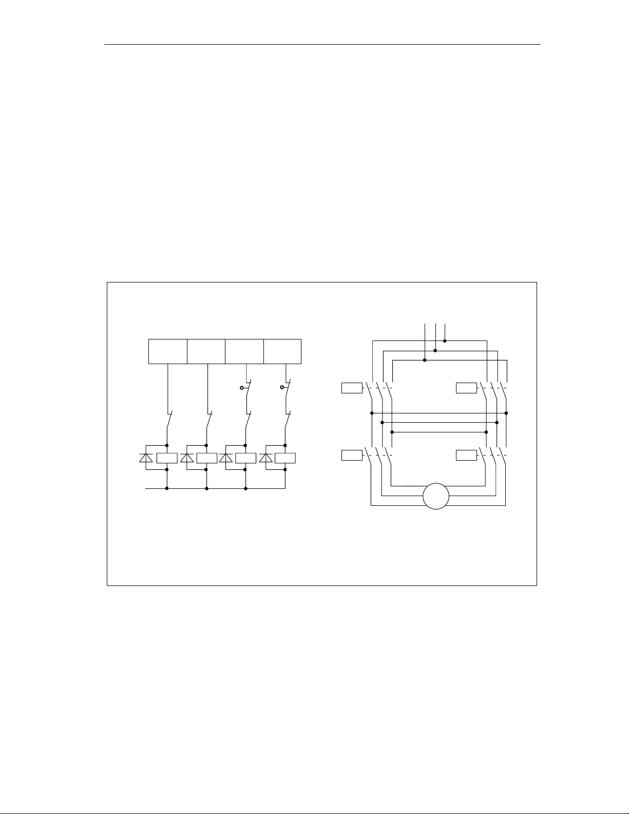
Contactor Circuit
Figure 4-3 shows the control and load current circuits of a power unit.
The functions of the digital outputs correspond to control mode 1
(see Section 8.3, page 8-6).
Digital outputs on FM 351
Wiring the FM 351
Load circuitControl circuit
L1 L2 L3
K3
1Q1
K3
K4
1Q0
NC
contact
of
K1 = direction plus
K2 = direction minus
K3 = rapid speed
K4 = creep speed
Figure 4-3 Contactor Circuit
K4
M
1Q2
K2
1Q3
E2
K1
K1
E1 = hardware limit switch minus
E2 = hardware limit switch plus
How the Contactor Circuit Works
K2
E1
K1
K3
K2
K4
M
Pole-changing motor
Contactors K1 and K2 control the direction of the motor. The contactors are
interlocked by the normally closed contacts K2 and K1. The hardware limit
switches E1 and E2 are the limit switches minus/plus. If the axis travels beyond
these limit switches, the motor (direction) is turned off.
The contactors K3 and K4 switch the motor from rapid to creep speed. The
contactors are interlocked by the normally closed contacts K4 and K3.
FM 351 Positioning Module
C79000-G7076-C351-02
4-7
Wiring the FM 351
!
Caution
Interlock the power network contactors.
Interlocking of the contactors is shown in Figure 4-3.
If you do not keep to this rule, a short circuit can occur in the main power network.
Note
Direct connection of inductive components (for example relays and contactors) is
possible without external wiring.
If SIMATIC output power circuits can be turned off by additionally installed
contacts (for example relay contacts), you must include additional surge protection
with inductive components (an example of surge protection is shown below).
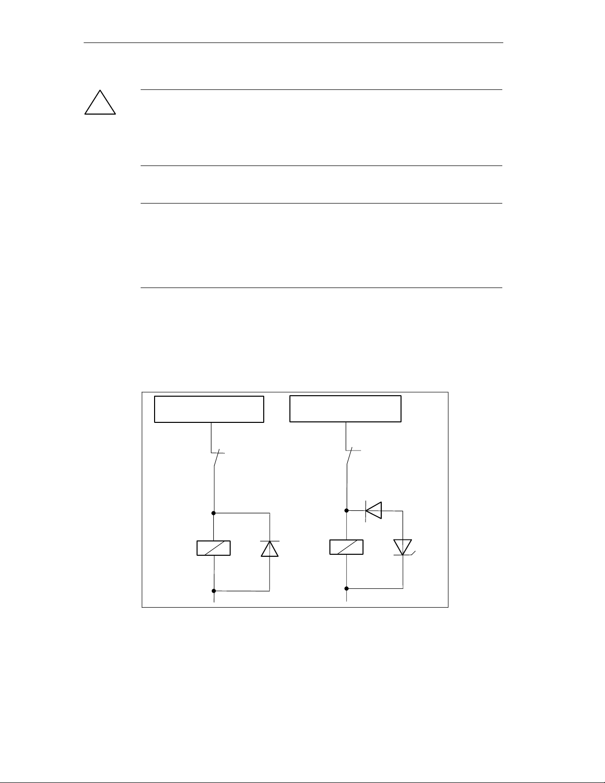
Example of Surge Protection
Figure 4-4 illustrates an output circuit that requires additional surge voltage
protection. Diodes or Z diodes are used with coils activated by direct current.
Digital output of the FM 351
e.g. 1Q0
Contact in output circuit
with diode
+
–
Figure 4-4 Relay in the Output Circuit
Digital output of the FM 351
e.g. 1Q0
with Z diode
+
–
4-8
FM 351 Positioning Module
C79000-G7076-C351-02
 Loading...