

Siemens SIMATIC ET200SP PS 6EP7133-6AB00-0BN0 24 V/5 A, SIMATIC ET200SP PS 6EP7133-6AE00-0BN0 24 V/10 A, SIMATIC ET200SP PS User Manual

___________________
___________________
___________________
___________________
___________________
___________________
___________________
___________________
___________________
___________________
___________________
___________________
SIMATIC system power supply
SIMATIC ET200SP PS
Manual
SIMATIC ET200SP PS
6EP7133
-6AB00-0BN0 24 V/5 A
SIMATIC ET200SP PS
6EP7133
-6AE00-0BN0 24 V/10 A
03.2018
A5E43207434
Overview
Safety instructions
1
Description, device design,
dimension drawing
2
Mounting/removal
3
Mounting position, mounting
clearances
4
Installation
5
Technical data
6
Safety, approvals, EMC
7
Environmental conditions
8
Applications
9
Environment
10
Service & Support
11
Siemens AG
Division Process Industries and Drives
Postfach 48 48
90026 NÜRNBERG
GERMANY
A5E43207434
Ⓟ
03/2018 Subject to change
Copyright © Siemens AG 2018.
All rights reserved
Legal information
Warning notice system
This manual contains notices you have to observe in order to ensure your personal safety, as well as to prevent
damage to property. The notices referring to your personal safety are highlighted in the manual by a safety alert
symbol, notices referring only to property damage have no safety alert symbol. These notices shown below are
graded according to the degree of danger.
DANGER
indicates that death or severe personal injury will result if proper precautions are not taken.
WARNING
indicates that death or severe personal injury may result if proper precautions are not taken.
CAUTION
indicates that minor personal injury can result if proper precautions are not taken.
NOTICE
indicates that property damage can result if proper precautions are not taken.
If more than one degree of danger is present, the warning notice representing the highest degree of danger will
be used. A notice warning of injury to persons with a safety alert symbol may also include a warning relating to
property damage.
Qualified Personnel
The product/system described in this documentation may be operated only by
personnel qualified
for the specific
task in accordance with the relevant documentation, in particular its warning notices and safety instructions.
Qualified personnel are those who, based on their training and experience, are capable of identifying risks and
avoiding potential hazards when working with these products/systems.
Proper use of Siemens products
Note the following:
WARNING
Siemens products may only be used for the applications described in the catalog and in the relevant technical
documentation. If products and components from other manufacturers are used, these must be recommended
or approved by Siemens. Proper transport, storage, installation, assembly, commissioning, operation and
maintenance are required to ensure that the products operate safely and without any problems. The permissible
ambient conditions must be complied with. The information in the relevant documentation must be observed.
Trademarks
All names identified by ® are registered trademarks of Siemens AG. The remaining trademarks in this publication
may be trademarks whose use by third parties for their own purposes could violate the rights of the owner.
Disclaimer of Liability
We have reviewed the contents of this publication to ensure consistency with the hardware and software
described. Since variance cannot be precluded entirely, we cannot guarantee full consistency. However, the
information in this publication is reviewed regularly and any necessary corrections are included in subsequent
editions.
SIMATIC ET200SP PS
Manual, 03.2018, A5E43207434
3
Overview
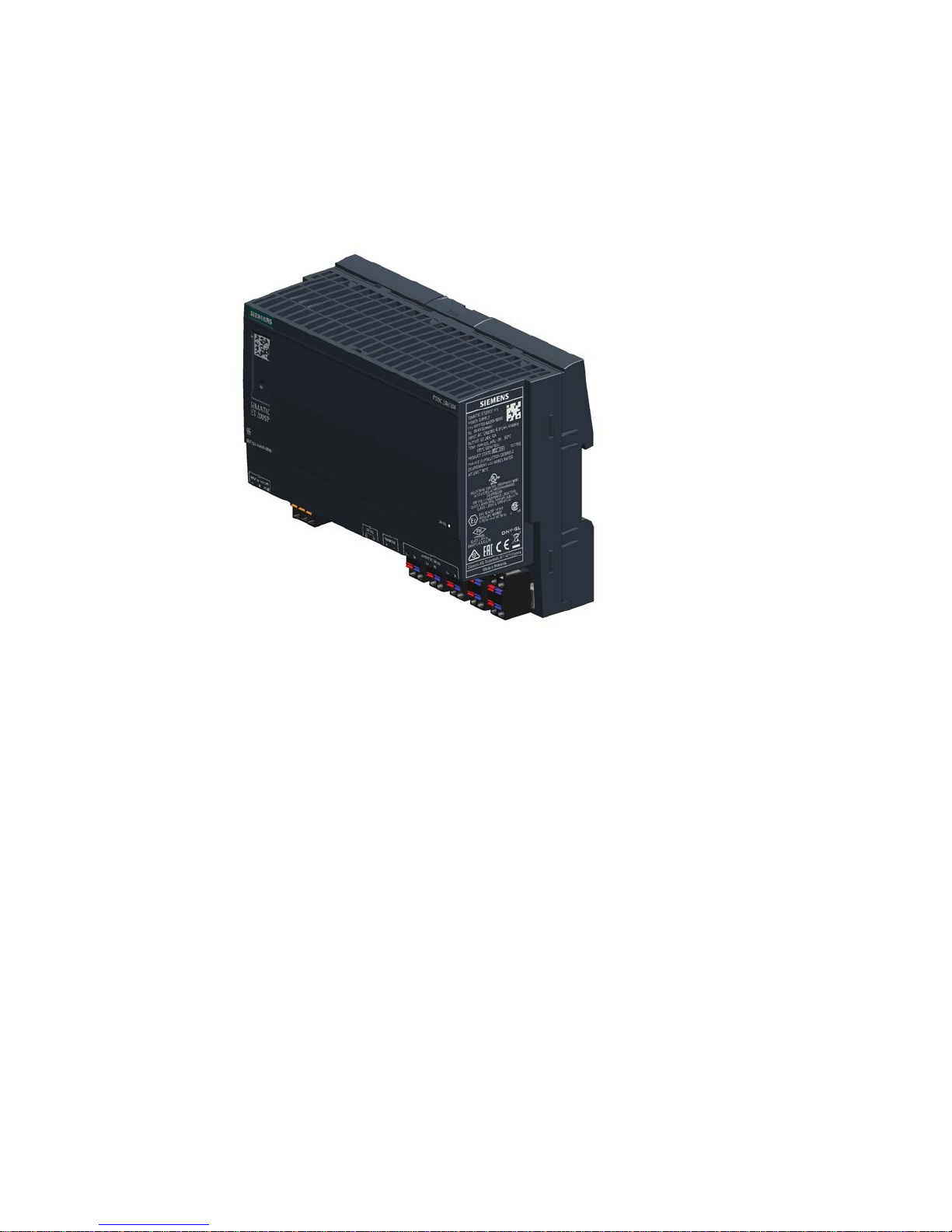
The 1-phase ET200SP PS from the SIMATIC ET200SP product line is a powerful regulated
system power supply for automated systems and machines. In addition to a high efficiency,
these power supply units have an outstanding overload behavior.
The key benefits of the product include:
● 1-phase 120/230 V AC input voltage with automatic switchover function allowing the units
to be connected to almost any 1-phase line supply around the world.
● The output voltage can be adjusted in the range 22.8 - 28 V
● Brief overload capability of 150% for 5 s/min (extra power)
● Integrated signaling contact for "24 V O.K."
● Ambient temperature -30 ... 70 °C

Overview
SIMATIC ET200SP PS
4 Manual, 03.2018, A5E43207434
Ordering data
The following device options are available:
Regulated power supply unit ET200SP PS
Type
Order number
1-phase 120/230 V AC input,
24 V/5 A DC output
6EP7133-6AB00-0BN0
1-phase 120/230 V AC input,
24 V/10 A DC output
6EP7133-6AE00-0BN0
Validity
This manual provides information on the following products:
● SIMATIC ET200SP PS 24 V DC/5 A, SIMATIC ET200SP PS 24 V DC/10 A
Article number: 6EP7133-6AB00-0BN0, 6EP7133-6AE00-0BN0
Product state (PS): 1

SIMATIC ET200SP PS
Manual, 03.2018, A5E43207434
5
Table of contents
Overview................................................................................................................................................. 3
1 Safety instructions ................................................................................................................................... 7
1.1 General safety instructions ....................................................................................................... 7
1.2 Safety instructions for hazardous zones ................................................................................... 7
2 Description, device design, dimension drawing........................................................................................ 9
2.1 Device description ..................................................................................................................... 9
2.2 Connections and terminal designation.................................................................................... 10
2.3 Potentiometer .......................................................................................................................... 11
2.4 Status displays and signaling ................................................................................................. 12
2.5 Block diagram ......................................................................................................................... 14
2.6 Dimensions and weight ........................................................................................................... 15
3 Mounting/removal ................................................................................................................................. 17
4 Mounting position, mounting clearances ................................................................................................ 19
4.1 Standard mounting position .................................................................................................... 19
4.2 Other mounting positions ........................................................................................................ 20
4.2.1 6EP7133-6AB00-0BN0 ........................................................................................................... 20
4.2.2 6EP7133-6AE00-0BN0 ........................................................................................................... 21
5 Installation ............................................................................................................................................ 23
5.1 Line-side connection ............................................................................................................... 23
5.2 Output-side connection ........................................................................................................... 25
6 Technical data ...................................................................................................................................... 27
6.1 Input ........................................................................................................................................ 27
6.2 Output ..................................................................................................................................... 29
6.3 Efficiency ................................................................................................................................. 32
6.4 Closed-loop control ................................................................................................................. 33
6.5 Protection and monitoring ....................................................................................................... 33
6.6 MTBF ...................................................................................................................................... 33
6.7 Mechanical system ................................................................................................................. 34
6.8 Dimension drawing ................................................................................................................. 34

Table of contents
SIMATIC ET200SP PS
6 Manual, 03.2018, A5E43207434
7 Safety, approvals, EMC ........................................................................................................................ 35
7.1 Safety ..................................................................................................................................... 35
7.2 Test voltage ............................................................................................................................ 36
7.3 Approvals ............................................................................................................................... 37
7.4 EMC ....................................................................................................................................... 37
8 Environmental conditions ...................................................................................................................... 39
9 Applications .......................................................................................................................................... 41
9.1 Parallel connection to increase the power rating ................................................................... 41
9.2 Series connection for increased voltage ................................................................................ 43
9.3 Overload protection in the 24 V output circuit ........................................................................ 44
9.4 Protection against short-time voltage dips ............................................................................. 45
9.5 Protecting against longer power failures ................................................................................ 46
10 Environment ......................................................................................................................................... 49
11 Service & Support ................................................................................................................................. 51
SIMATIC ET200SP PS
Manual, 03.2018, A5E43207434
7
1
1.1
General safety instructions
WARNING
Correct handling of the devices
When operating electrical devices, it is inevitable that certain components will carry
dangerous voltages.
Therefore, failure to handle the units properly can result in death or serious physical injury
as well as extensive property damage.
Only appropriately qualified personnel may work on or in the vicinity of this equipment.
Perfect, safe, and reliable operation of this equipment is dependent on proper
transportation, storage, installation and mounting.
Before installation or maintenance work can begin, the system's main switch must be
switched off and measures taken to prevent it being switched on again.
If this instruction is not observed, touching live parts can result in death or serious injury.
1.2
Safety instructions for hazardous zones
WARNING
OPERATE POTENTIOMETERS OR SWITCHES IN NON-HAZARDOUS AREAS ONLY!

Safety instructions
1.2 Safety instructions for hazardous zones
SIMATIC ET200SP PS
8 Manual, 03.2018, A5E43207434
SIMATIC ET200SP PS
Manual, 03.2018, A5E43207434
9
2
2.1
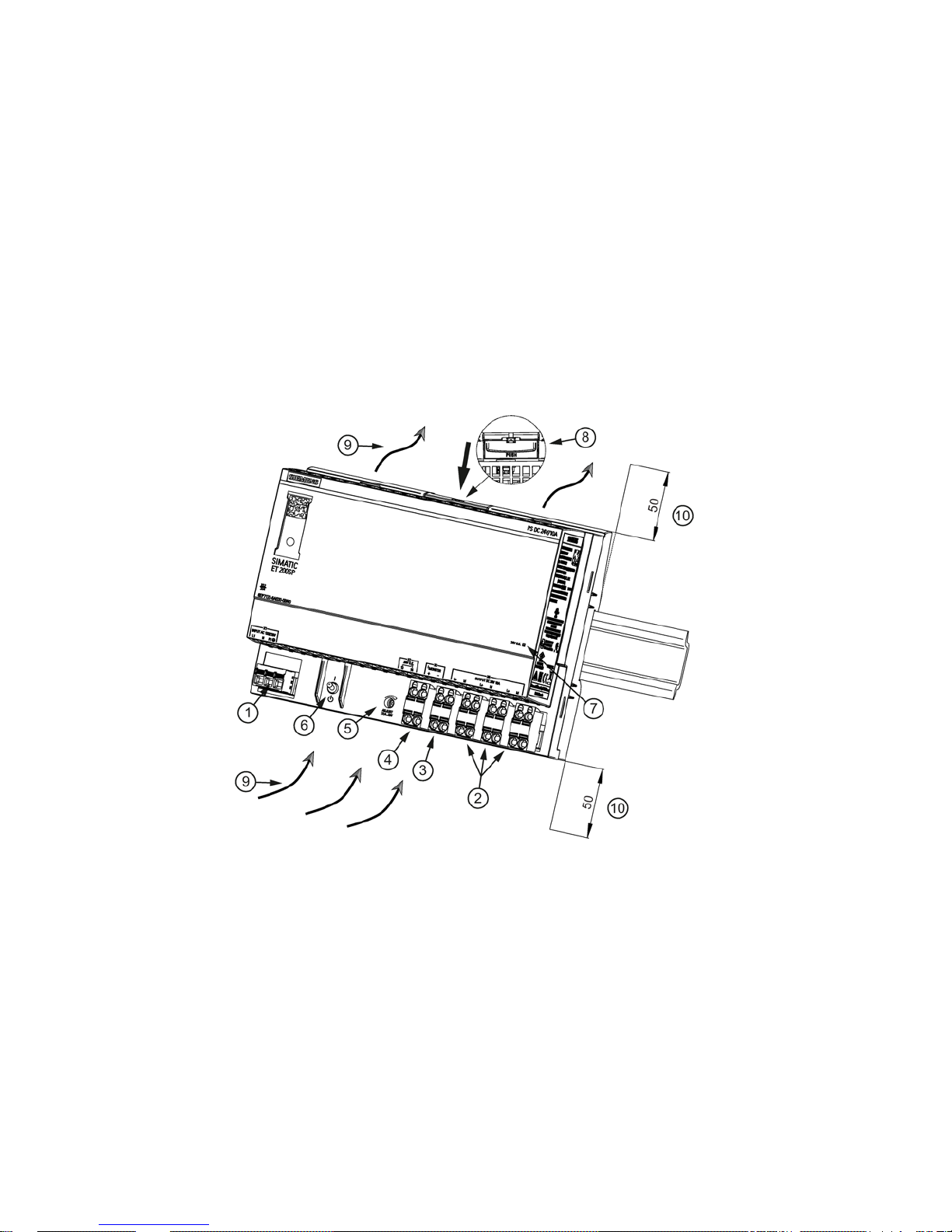
Device description
The SIMATIC ET200SP PS is a primary-clocked power supply for connection to a 1-phase
AC line supply. An electronically regulated DC voltage that can be set via a potentiometer is
available at the output of the device. The output of the device is isolated, no-load proof and
short-circuit proof. The LED display indicates the operating status. The current monitoring
terminal is used to sense the output current. The operating state of the device can be
processed via the signaling contact.
①
AC input
②
DC output
③
Current monitoring terminals I
Monitor
(1 V ≙ I
out rated
)
④
Signaling contact (13, 14)
⑤
Potentiometer 22.8 – 28 V
⑥
ON/OFF switch
⑦
Indicator light (24 V O.K.)
⑧
Button to manually release
⑨
Convection
⑩
Clearance above/below
Figure 2-1 Design
Description, device design, dimension drawing
2.2 Connections and terminal designation
SIMATIC ET200SP PS
10 Manual, 03.2018, A5E43207434
2.2
Connections and terminal designation
The line input terminals ① can be used to establish the connection to supply voltage.
The output terminals
② are used to connect to the loads to be supplied (see also Section
Installation (Page 23)).
The output current can be sensed via current monitoring terminal
③. The operating state of
the device can be processed via the signaling contact
④ (function and contact rating, see
Chapter Status displays and signaling (Page 12)).
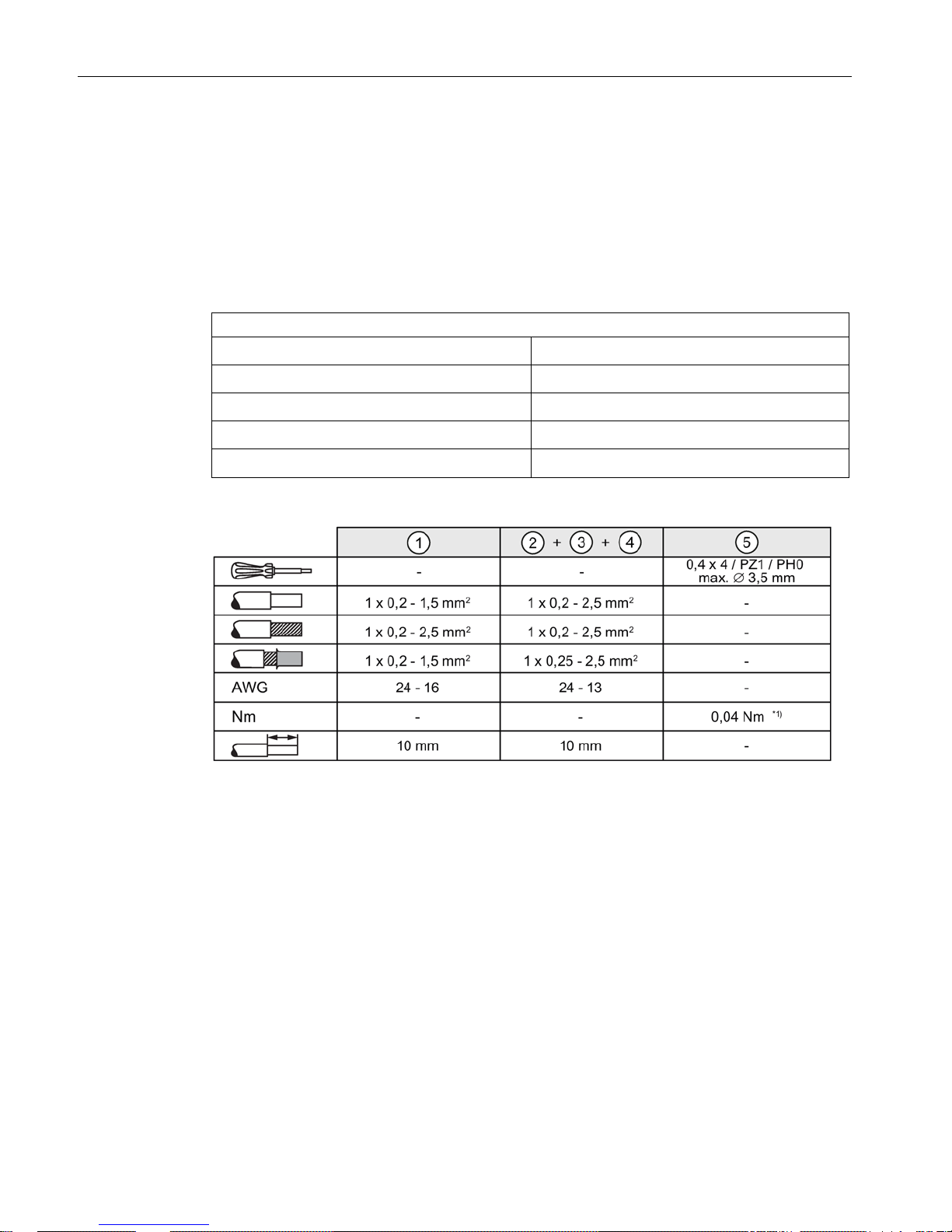
Connections and terminal designations
①
Line input L1, N, PE
One spring-loaded terminal each
②
Output +
3 spring-loaded terminals
②
Output –
3 spring-loaded terminals
③
Current monitoring terminals
One spring-loaded terminal each
④
Signaling contact 13, 14
One spring-loaded terminal each
*1)
Do not subject the end stop to higher loads
Figure 2-2 Terminal data
Description, device design, dimension drawing
2.3 Potentiometer
SIMATIC ET200SP PS
Manual, 03.2018, A5E43207434
11
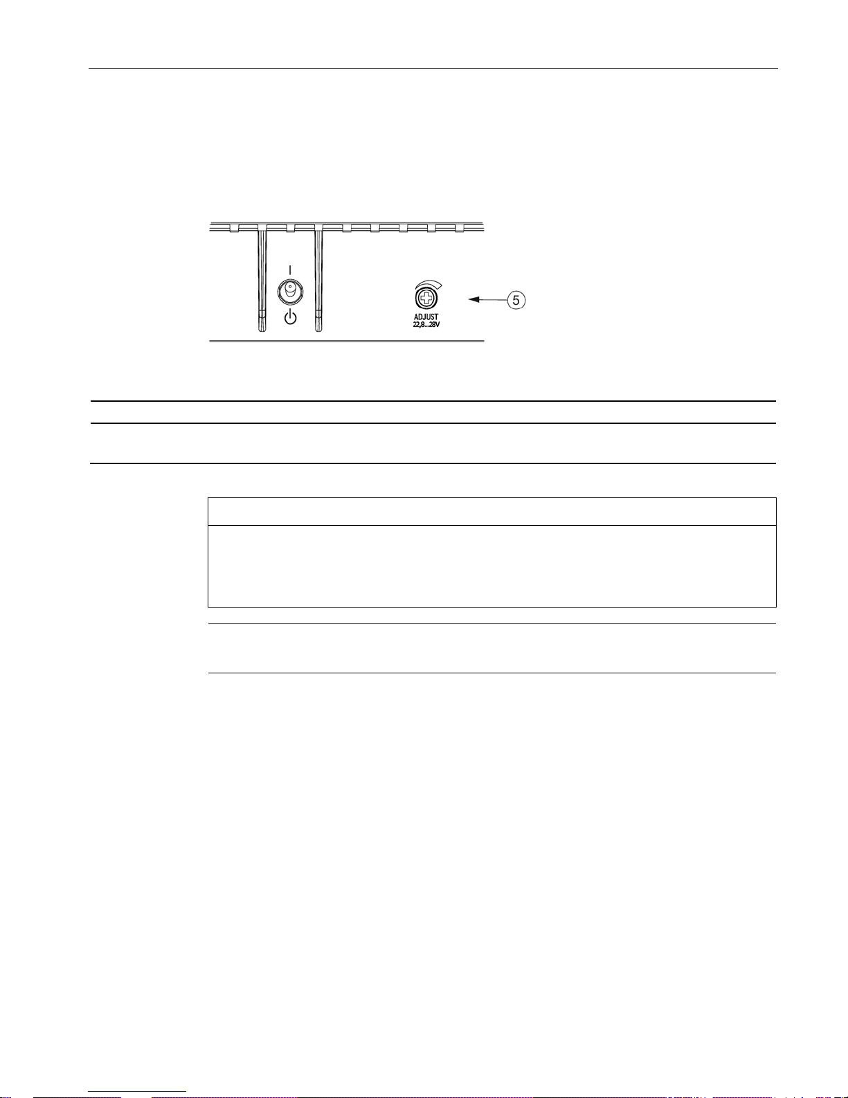
2.3
Potentiometer
The potentiometer ⑤ on the front of the device is used to set the output voltage.
The output voltage is set to the rated value at the factory and can be set within certain limits;
for example, to compensate voltage drops across long supply lines to the connected load.
Figure 2-3 Potentiometer
Type
Factory setting
Adjustment range
6EP7133-6AB00-0BN0
6EP7133-6AE00-0BN0
24 V 22.8 - 28 V
NOTICE
Thermal overload possible
When adjusting the output voltage to greater than the rated voltage, the output current must
be derated by 4 %/V, or the permissible ambient temperature must be taken into account
with 3° C/V.
Note
It is only permissible to use an insulated
screwdriver when actuating the potentiometer.
For information on actuating the potentiometer (screwdriver, torque), see Figure 2-2
Terminal data (Page 10).
Description, device design, dimension drawing
2.4 Status displays and signaling
SIMATIC ET200SP PS
12 Manual, 03.2018, A5E43207434
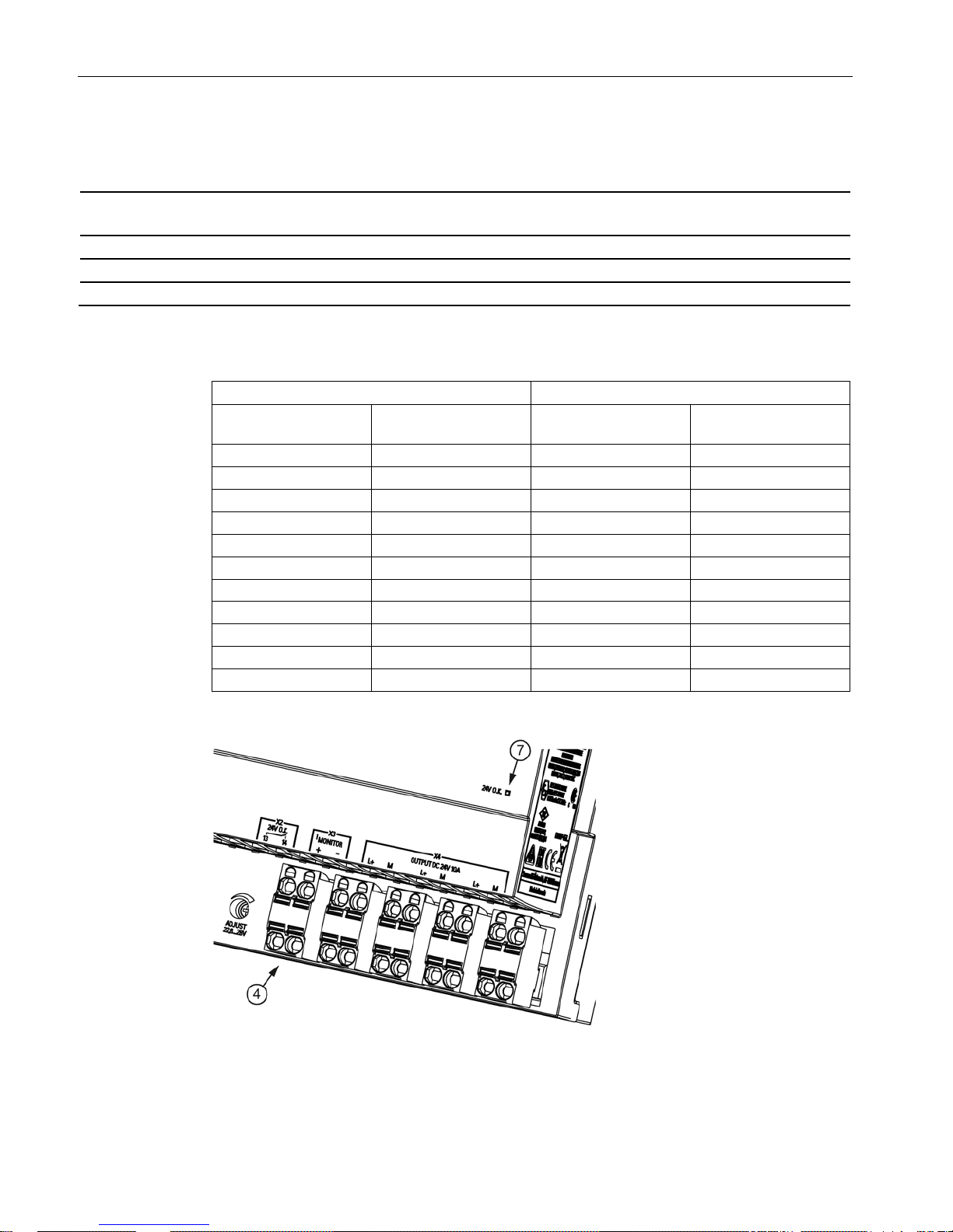
2.4
Status displays and signaling
6EP7133-6AB00-0BN0 (24 /5 A)
6EP7133-6AE00-0BN0 (24 V/10 A)
Status display
LED green for 24 V O.K.
Signaling contact (13,14)
Contact rating (isolated): 30 V AC/0.5 A, 60 V DC/0.3 A, 30 V DC/1 A) for 24 V O.K.
Current monitoring terminals
Voltage proportional to the output current: ~ 1 V ≙ I
out rated
±50 mV
Table 2- 1 I
Monitor
conversion table
6EP7133-6AB00-0BN0 (24 V/5 A)
6EP7133-6AE00-0BN0 (24 V/10 A)
Output current
[A]
I
Monitor
[V]
Output current
[A]
I
Monitor
[V]
0.0
0.0
0.0
0.0
0.5
0.1
1.0
0.1
1.0
0.2
2.0
0.2
1.5
0.3
3.0
0.3
2.0
0.4
4.0
0.4
2.5
0.5
5.0
0.5
3.0
0.6
6.0
0.6
3.5
0.7
7.0
0.7
4.0
0.8
8.0
0.8
4.5
0.9
9.0
0.9
5.0
1.0
10
1.0
Figure 2-4 Operating displays and signaling

Description, device design, dimension drawing
2.4 Status displays and signaling
SIMATIC ET200SP PS
Manual, 03.2018, A5E43207434
13
Signaling
6EP7133-6AB00-0BN0 (24 /5 A)
6EP7133-6AE00-0BN0 (24 V/10 A)
LED ⑦ lights up green
Signaling contact ④,
contact 13-14 closed
Normal operation, output voltage > 20 V ±0.5 V
LED ⑦ off
Signaling contact ④,
contacts 13-14 open (quiescent position)
Overload operation or power supply voltage missing
Description, device design, dimension drawing
2.5 Block diagram
SIMATIC ET200SP PS
14 Manual, 03.2018, A5E43207434
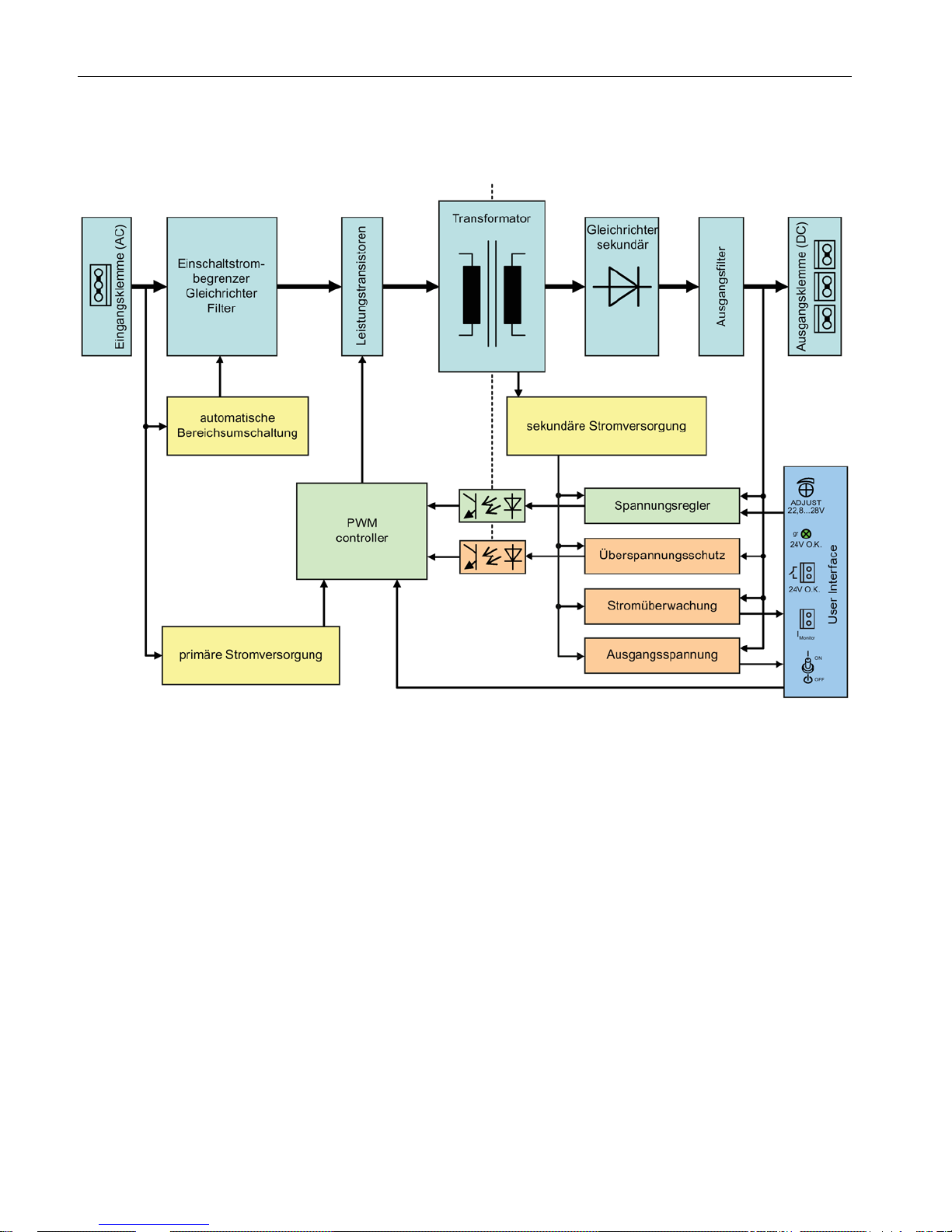
2.5
Block diagram
Figure 2-5 Block diagram
Description, device design, dimension drawing
2.6 Dimensions and weight
SIMATIC ET200SP PS
Manual, 03.2018, A5E43207434
15
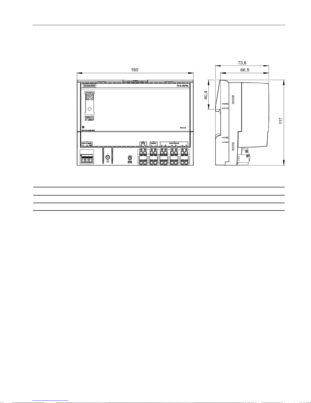
2.6
Dimensions and weight
Figure 2-6 Dimensions and weight
6EP7133-6AB00-BN0 (24 V/5 A)
6EP7133-6AE00-0BN0 (24 V/10 A)
Dimensions (W × H × D) in mm
160 × 117 × 66.5
160 × 117 × 66.5
Weight
Approx. 0.5 kg
Approx. 0.72 kg

Description, device design, dimension drawing
2.6 Dimensions and weight
SIMATIC ET200SP PS
16 Manual, 03.2018, A5E43207434
 Loading...