

Siemens SIMATIC ET 200SP IM 155-6 PN/2 HF User Manual

___________________
___________________
___________________
___________________
___________________
___________
___________________
___________________
___________________
SIMATIC
ET 200SP
Interface module IM 155-6 PN/2 HF
(6ES7155-6AU01-0CN0)
Manual
10/2018
A5E03915895
Preface
Guide
1
Product overview
2
Wiring
3
Parameters/address space
4
Interrupts, error messages,
diagnostics and system
alarms
5
Compatibility
6
Technical specifications
7
Dimension drawing
A
-AH

Siemens AG
Division Digital Factory
Postfach 48 48
90026 NÜRNBERG
GERMANY
A5E03915895-AH
Ⓟ
Copyright © Siemens AG 2013 - 2018.
All rights reserved
Legal information
Warning notice system
DANGER
indicates that death or severe personal injury will result if proper precautions are not taken.
WARNING
indicates that death or severe personal injury may result if proper precautions are not taken.
CAUTION
indicates that minor personal injury can result if proper precautions are not taken.
NOTICE
indicates that property damage can result if proper precautions are not taken.
Qualified Personnel
personnel qualified
Proper use of Siemens products
WARNING
Siemens products may only be used for the applications described in the catalog and in the relevant technical
ambient conditions must be complied with. The information in the relevant documentation must be observed.
Trademarks
Disclaimer of Liability
This manual contains notices you have to observe in order to ensure your personal safety, as well as to prevent
damage to property. The notices referring to your personal safety are highlighted in the manual by a safety alert
symbol, notices referring only to property damage have no safety alert symbol. These notices shown below are
graded according to the degree of danger.
If more than one degree of danger is present, the warning notice representing the highest degree of danger will
be used. A notice warning of injury to persons with a safety alert symbol may also include a warning relating to
property damage.
The product/system described in this documentation may be operated only by
task in accordance with the relevant documentation, in particular its warning notices and safety instructions.
Qualified personnel are those who, based on their training and experience, are capable of identifying risks and
avoiding potential hazards when working with these products/systems.
Note the following:
documentation. If products and components from other manufacturers are used, these must be recommended
or approved by Siemens. Proper transport, storage, installation, assembly, commissioning, operation and
maintenance are required to ensure that the products operate safely and without any problems. The permissible
All names identified by ® are registered trademarks of Siemens AG. The remaining trademarks in this publication
may be trademarks whose use by third parties for their own purposes could violate the rights of the owner.
We have reviewed the contents of this publication to ensure consistency with the hardware and software
described. Since variance cannot be precluded entirely, we cannot guarantee full consistency. However, the
information in this publication is reviewed regularly and any necessary corrections are included in subsequent
editions.
for the specific
10/2018 Subject to change

Preface
Purpose of the documentation
Conventions
Note
A note contains important information on the product described in t
handling of the product, or on the section of the documentation to which particular attention
should be paid.
Recycling and disposal
This manual supplements the ET 200SP distributed I/O system
(http://support.automation.siemens.com/WW/view/en/58649293) system manual.
Functions that generally relate to the system are described in this manual.
The information provided in this manual and in the system/function manuals supports you in
commissioning the ET 200SP distributed I/O system.
Please also observe notes labeled as follows:
For environmentally friendly recycling and disposal of your old equipment, contact a certified
electronic waste disposal company and dispose of the equipment according to the applicable
regulations in your country.
he documentation, on the
Interface module IM 155-6 PN/2 HF (6ES7155-6AU01-0CN0)
Manual, 10/2018, A5E03915895-AH
3

Preface
Security information
Siemens provides products and solutions with industrial security functions that support the
secure operation of plants, systems, machines and networks.
In order to protect plants, systems, machines and networks against cyber threats, it is
necessary to implement – and continuously maintain – a holistic, state-of-the-art industrial
security concept. Siemens' products and solutions constitute one element of such a concept.
Customers are responsible for preventing unauthorized access to their plants, systems,
machines and networks. Such systems, machines and components should only be
connected to an enterprise network or the internet if and to the extent such a connection is
necessary and only when appropriate security measures (e.g. firewalls and/or network
segmentation) are in place.
For additional information on industrial security measures that may be implemented, please
visit (https://www.siemens.com/industrialsecurity).
Siemens' products and solutions undergo continuous development to make them more
secure. Siemens strongly recommends that product updates are applied as soon as they are
available and that the latest product versions are used. Use of product versions that are no
longer supported, and failure to apply the latest updates may increase customers' exposure
to cyber threats.
To stay informed about product updates, subscribe to the Siemens Industrial Security RSS
Feed under (https://www.siemens.com/industrialsecurity).
Interface module IM 155-6 PN/2 HF (6ES7155-6AU01-0CN0)
4 Manual, 10/2018, A5E03915895-AH

Table of contents
Preface ................................................................................................................................................... 3
1 Guide ...................................................................................................................................................... 7
2 Product overview .................................................................................................................................. 12
3 Wiring ................................................................................................................................................... 30
4 Parameters/address space ................................................................................................................... 32
2.1 Properties ................................................................................................................................ 12
2.2 Functions ................................................................................................................................ 16
2.2.1 Device replacement ................................................................................................................ 20
2.2.2 Real-time communication ....................................................................................................... 21
2.2.3 Isochronous real-time communication .................................................................................... 21
2.2.4 Prioritized startup .................................................................................................................... 22
2.2.5 Submodules ............................................................................................................................ 22
2.2.6 Media redundancy (MRP) ....................................................................................................... 23
2.2.7 Shared device ......................................................................................................................... 23
2.2.8 Isochronous mode .................................................................................................................. 24
2.2.9 Module-internal Shared Input/Shared Output (MSI/MSO) ...................................................... 24
2.2.10 System redundancy S2 ........................................................................................................... 25
2.2.11 Alternating IO devices during operation ("docking systems") ................................................. 25
2.2.12 Oversampling .......................................................................................................................... 25
2.2.13 Value status ............................................................................................................................ 26
2.2.14 PROFIenergy .......................................................................................................................... 26
2.2.15 Configuration control (option handling) ................................................................................... 27
2.2.16 Use of fail-safe modules ......................................................................................................... 27
2.2.17 Multi Hot Swap ........................................................................................................................ 27
2.2.18 Module-to-Module Communication (MtM) .............................................................................. 28
2.2.19 Setting the time ....................................................................................................................... 29
3.1 Pin assignment ....................................................................................................................... 30
3.2 Block diagram ......................................................................................................................... 31
4.1 Parameters ............................................................................................................................. 32
4.2 Explanation of parameters ...................................................................................................... 32
4.2.1 Enable configuration control ................................................................................................... 32
4.2.2 Diagnostics (maintenance) undervoltage ............................................................................... 33
4.3 Substitute value behavior ....................................................................................................... 33
4.4 Status of the supply voltage L+ of the I/O modules ................................................................ 34
Interface module IM 155-6 PN/2 HF (6ES7155-6AU01-0CN0)
Manual, 10/2018, A5E03915895-AH
5

Table of contents
5 Interrupts, error messages, diagnostics and system alarms ................................................................... 35
6 Compatibility ......................................................................................................................................... 48
7 Technical specifications ........................................................................................................................ 52
A Dimension drawing ............................................................................................................................... 56
5.1 Status and error displays ....................................................................................................... 35
5.2 Interrupts ................................................................................................................................ 38
5.2.1 Triggering of a diagnostics interrupt....................................................................................... 39
5.2.2 Triggering a hardware interrupt.............................................................................................. 39
5.2.3 Triggering of a remove/insert module interrupt ...................................................................... 40
5.3 Alarms .................................................................................................................................... 41
5.3.1 Diagnostics alarms ................................................................................................................. 41
5.3.2 Maintenance events ............................................................................................................... 42
5.3.3 Channel diagnostics ............................................................................................................... 43
5.3.4 Invalid configuration states of the ET 200SP on PROFINET IO ............................................ 46
5.3.5 Failure of supply voltage L+ at BaseUnit BU...D ................................................................... 47
5.3.6 STOP of the IO controller and recovery of the IO device ...................................................... 47
6.1 Compatibility of modules ........................................................................................................ 48
Interface module IM 155-6 PN/2 HF (6ES7155-6AU01-0CN0)
6 Manual, 10/2018, A5E03915895-AH
1
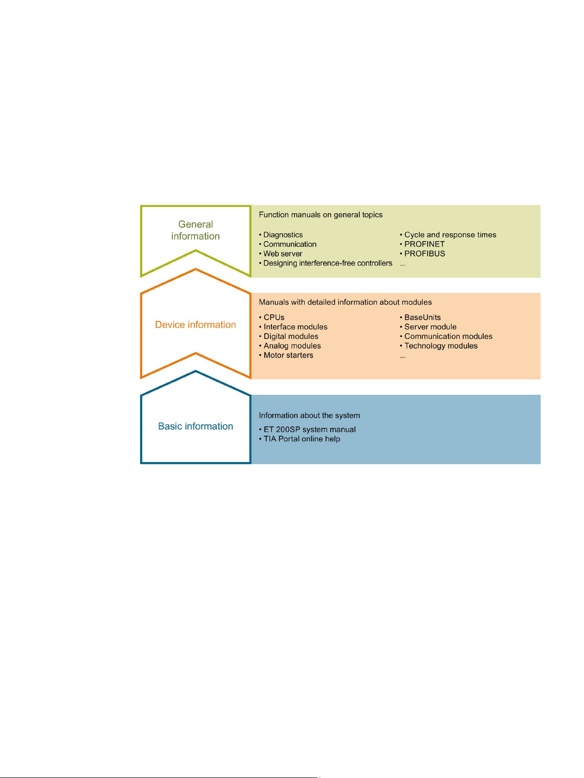
Basic information
Device information
The documentation for the SIMATIC ET 200SP distributed I/O system is arranged into three
areas.
This arrangement enables you to access the specific content you require.
The system manual describes in detail the configuration, installation, wiring and
commissioning of the SIMATIC ET 200SP. distributed I/O system. The STEP 7 online help
supports you in the configuration and programming.
Product manuals contain a compact description of the module-specific information, such as
properties, wiring diagrams, characteristics and technical specifications.
Interface module IM 155-6 PN/2 HF (6ES7155-6AU01-0CN0)
Manual, 10/2018, A5E03915895-AH
7

Guide
General information
Manual Collection ET 200SP
"mySupport"
"mySupport" - Documentation
The function manuals contain detailed descriptions on general topics regarding the SIMATIC
ET 200SP distributed I/O system, e.g. diagnostics, communication, Web server, motion
control and OPC UA.
You can download the documentation free of charge from the Internet
(https://support.industry.siemens.com/cs/ww/en/view/109742709).
Changes and supplements to the manuals are documented in a Product Information.
You can download the product information free of charge from the Internet
(https://support.industry.siemens.com/cs/us/en/view/73021864).
The Manual Collection contains the complete documentation on the SIMATIC ET 200SP
distributed I/O system gathered together in one file.
You can find the Manual Collection on the Internet
(https://support.automation.siemens.com/WW/view/en/84133942).
With "mySupport", your personal workspace, you make the most of your Industry Online
Support.
In "mySupport" you can store filters, favorites and tags, request CAx data and put together
your personal library in the Documentation area. Furthermore, your data is automatically
filled into support requests and you always have an overview of your current requests.
You need to register once to use the full functionality of "mySupport".
You can find "mySupport" in the Internet (https://support.industry.siemens.com/My/ww/en).
In the Documentation area of "mySupport", you have the possibility to combine complete
manuals or parts of them to make your own manual.
You can export the manual in PDF format or in an editable format.
You can find "mySupport" - Documentation in the Internet
(https://support.industry.siemens.com/My/ww/en/documentation).
Interface module IM 155-6 PN/2 HF (6ES7155-6AU01-0CN0)
8 Manual, 10/2018, A5E03915895-AH

Guide
"mySupport" - CAx Data
Application examples
TIA Selection Tool
In the CAx Data area of "mySupport", you can have access the latest product data for your
CAx or CAe system.
You configure your own download package with a few clicks.
In doing so you can select:
● Product images, 2D dimension drawings, 3D models, internal circuit diagrams, EPLAN
macro files
● Manuals, characteristics, operating manuals, certificates
● Product master data
You can find "mySupport" - CAx Data in the Internet
(https://support.industry.siemens.com/my/ww/en/CAxOnline).
The application examples support you with various tools and examples for solving your
automation tasks. Solutions are shown in interplay with multiple components in the system separated from the focus in individual products.
You can find the application examples on the Internet
(https://support.industry.siemens.com/sc/ww/en/sc/2054).
With the TIA Selection Tool, you can select, configure and order devices for Totally
Integrated Automation (TIA).
This tool is the successor of the SIMATIC Selection Tool and combines the known
configurators for automation technology into one tool.
With the TIA Selection Tool, you can generate a complete order list from your product
selection or product configuration.
You can find the TIA Selection Tool on the Internet
(https://w3.siemens.com/mcms/topics/en/simatic/tia-selection-tool).
Interface module IM 155-6 PN/2 HF (6ES7155-6AU01-0CN0)
Manual, 10/2018, A5E03915895-AH
9

Guide
SIMATIC Automation Tool
PRONETA
You can use the SIMATIC Automation Tool to run commissioning and maintenance activities
simultaneously on various SIMATIC S7 stations as a bulk operation independently of the
TIA Portal.
The SIMATIC Automation Tool provides a multitude of functions:
● Scanning of a PROFINET/Ethernet network and identification of all connected CPUs
● Address assignment (IP, subnet, gateway) and station name (PROFINET device) to a
CPU
● Transfer of the data and the programming device/PC time converted to UTC time to the
module
● Program download to CPU
● Operating mode switchover RUN/STOP
● Localization of the CPU by means of LED flashing
● Reading out CPU error information
● Reading the CPU diagnostic buffer
● Reset to factory settings
● Updating the firmware of the CPU and connected modules
You can find the SIMATIC Automation Tool on the Internet
(https://support.industry.siemens.com/cs/ww/en/view/98161300).
With SIEMENS PRONETA (PROFINET network analysis), you analyze the plant network
during commissioning. PRONETA features two core functions:
● The topology overview independently scans PROFINET and all connected components.
● The IO check is a fast test of the wiring and the module configuration of a system.
You can find SIEMENS PRONETA on the Internet
(https://support.industry.siemens.com/cs/ww/en/view/67460624).
Interface module IM 155-6 PN/2 HF (6ES7155-6AU01-0CN0)
10 Manual, 10/2018, A5E03915895-AH

Guide
SINETPLAN
SINETPLAN, the Siemens Network Planner, supports you in planning automation systems
and networks based on PROFINET. The tool facilitates professional and predictive
dimensioning of your PROFINET installation as early as in the planning stage. In addition,
SINETPLAN supports you during network optimization and helps you to exploit network
resources optimally and to plan reserves. This helps to prevent problems in commissioning
or failures during productive operation even in advance of a planned operation. This
increases the availability of the production plant and helps improve operational safety.
The advantages at a glance
● Network optimization thanks to port-specific calculation of the network load
● Increased production availability thanks to online scan and verification of existing systems
● Transparency before commissioning through importing and simulation of existing STEP 7
projects
● Efficiency through securing existing investments in the long term and optimal exploitation
of resources
You can find SINETPLAN on the Internet (https://www.siemens.com/sinetplan).
Interface module IM 155-6 PN/2 HF (6ES7155-6AU01-0CN0)
Manual, 10/2018, A5E03915895-AH
11

2
2.1
Properties
Article number
View of the module
6ES7155-6AU01-0CN0
Figure 2-1 View of the AS interface module 155-6 PN/2 HF with included accessory (24 V DC
connector and server module) and optional accessories (labeling strips and reference
identification label)
Interface module IM 155-6 PN/2 HF (6ES7155-6AU01-0CN0)
12 Manual, 10/2018, A5E03915895-AH

Product overview
Properties
Maximum configuration
Maximum amount of I/O data
Gross data length (for input data and output data):
2.1 Properties
The module has the following technical properties:
● Connects the ET 200SP distributed I/O system with PROFINET IO.
● Power supply 1 L+ 24 V DC (SELV/PELV). The connection plug is included in the scope
of delivery of the interface module and is available as replacement part.
● PROFINET IO connection via selectable BusAdapters
– BA 2×RJ45 for RJ45 bus connector
– BA 2×FC for direct connection of the bus cable
– BA 2xLC for glass fiber-optic cable
– BA 2xSCRJ for POF/PCF fiber-optic cable
– BA SCRJ/RJ45 as media converter for POF/PCF fiber-optic cable ⇔ standard RJ45
connector
– BA SCRJ/FC as media converter for POF/PCF fiber-optic cable ⇔ direct connection of
the bus cable
– BA LC/RJ45 as media converter for glass fiber-optic cable ⇔ standard RJ45 connector
– BA LC/FC as media converter for glass fiber-optic cable ⇔ direct connection of the
bus cable
● 64 ET 200SP I/O modules + 16 ET 200AL modules
● 1 m backplane bus (without interface and server module)
Without system redundancy S2:
● 1440 bytes
● 1440 bytes for shared device with 2 IOC (in total for both IOC)
● 360 bytes for shared device with more than 2 IOC (per IOC)
With system redundancy S2:
● 1000 bytes
● 360 bytes for system redundancy S2 and shared device with min. 1 additional IOC (per
IOC)
The number of maximum net data length for input data and output data depends on the
number and type of I/O modules used including ET 200AL modules.
Interface module IM 155-6 PN/2 HF (6ES7155-6AU01-0CN0)
Manual, 10/2018, A5E03915895-AH
13

Product overview
Net data length (for input data and output data):
Calculation of the max. net data length:
Accessories
Server module
2.1 Properties
The following minimum lengths can be applied without shared device and without explicit
calculation of the maximum net data length.
● 933 bytes without system redundancy S2
● 493 bytes with system redundancy S2
Max. net data length = Max. gross length - number of I/O submodules (no user data, input or
output data) - number of I/O mixed modules (input and output data) - 5 bytes for interface
module and server module without ET-Connection (6 bytes for interface module with
ET-Connection)
The result of the calculation of the maximum net data length applies equally to input and
output data.
You order the following accessories separately:
● BA 2×RJ45 BusAdapter
● BA 2×FC BusAdapter
● BA 2×LC BusAdapter
● BA 2xSCRJ BusAdapter
● BA SCRJ/RJ45 BusAdapter
● BA SCRJ/FC BusAdapter
● BA LC/RJ45 BusAdapter
● BA LC/FC BusAdapter
● Strain relief for PROFINET cable
● 24 V DC connector (one included in the scope of delivery)
● Labeling strips
● Reference identification label
Information on the BusAdapters is available in the BusAdapter
(https://support.industry.siemens.com/cs/ww/en/view/109751716) manual.
You can find more information on accessories in the ET 200SP distributed I/O system
(http://support.automation.siemens.com/WW/view/en/58649293) system manual.
The server module is included in the scope of delivery of the interface module and available
separately as an accessory.
Interface module IM 155-6 PN/2 HF (6ES7155-6AU01-0CN0)
14 Manual, 10/2018, A5E03915895-AH

Product overview
Note
You need to configure and assign parameters to the server module in the configuration
software.
Place the server module in the last slot of the configuration. If there are 64 I/O modules, the
server modu
First BaseUnit of an ET 200SP in the configuration
Note
First BaseUnit of an ET 200SP in the configuration
Please note the information on limiting the overvoltage and pow
module manuals.
You route the infeed of the 24
The 24
See also
2.1 Properties
The server module has the following properties:
● Terminates the backplane bus of the ET 200SP distributed I/O system
● Includes a holder for 3 spare fuses (5 × 20 mm).
● Provides station functions, e.g., group diagnostics: No supply voltage L+, status bytes.
● Identification data I&M 0 to 4
le is plugged in slot 65.
You can find more information in the Server module
(http://support.automation.siemens.com/WW/view/en/63257531) manual.
The interface modules support plugging a dark-colored BaseUnit in slot 1. This means that
modules without a connection to the integrated voltage buses P1 and P2 can now also be
configured starting with slot 1. Currently, this applies to the following modules:
● AI Energy Meter ST
● DI 4 x 120…230 V AC ST (6ES7131-6FD00-0BB1)
● DQ 4 x 24…230 V AC/2 A ST (6ES7132-6FD00-0BB1)
V DC supply voltage over an external fuse.
V DC supply voltage is provided by a light-colored BaseUnit.
Requirement for configuration of these modules in slot 1:
● Configuration via GSD or GSDML
● Configuration as of STEP 7 V5.5 SP4 with
er rating in the AC I/O
– HSP0255 V3.0 for IM155-6 PN HF
● Configuration as of STEP 7 V13 SP1
Interface module IM 155-6 PN/2 HF (6ES7155-6AU01-0CN0)
Manual, 10/2018, A5E03915895-AH
Functions (Page 16)
15

Product overview
2.2
Functions
Introduction
2.2 Functions
The interface module supports the following PROFINET IO functions:
● Integrated switch with 2 ports
● Supported Ethernet services: PING, ARP, SNMP, LLDP
● Port diagnostics
● Disabling ports
● Minimum update time 250 µs
● Device replacement without programming device, also without topological configuration
● Reset to factory settings via PROFINET IO or RESET button
● Firmware update via PROFINET IO
● Isochronous real-time communication
● Prioritized startup
● Media redundancy (MRP)
● Shared device
● Distribution of module channels to a maximum of 4 submodules
● Module-internal or submodule-internal Shared Input/Shared Output (MSI/MSO)
● Isochronous mode
● System redundancy S2
● Station extension via ET-Connection
● Alternating IO devices during operation ("docking systems")
– Docking station
– Docking unit
● Supports BusAdapter for different connection technologies to PROFINET IO.
The interface module supports additional functions:
● Identification data I&M 0 to I&M 4
● PROFIenergy
● Configuration control (option handling)
● Use of fail-safe modules
● Removal/insertion of multiple I/O modules during operation (Multi Hot Swap)
● Module-to-Module Communication (MtM)
Interface module IM 155-6 PN/2 HF (6ES7155-6AU01-0CN0)
16 Manual, 10/2018, A5E03915895-AH

Product overview
Requirements
Function
Functional
status of
the module
as of
Firmware
version of
the module
as of
Configuration software
Configuration with
GSD file
(http://support.auto
mation.siemens.co
m/WW/view/en/19
698639/130000)/s
oftware from a
third-party manu-
facturer 1
STEP 7 as of
V5.5 SP3
with HSP 233
STEP 7 as of
V5.5 SP4 with
HSP 250/255
STEP 7 (TIA
Portal) as of
V12.0.1 with
HSP 0058
Real-time communication
1
V2.0.0 X X X X
communication
Prioritized startup
1
V2.0.0 X X X X
out programming device
Media redundancy (MRP)
1
V2.0.0 X X X X
Shared device
1
V2.0.0 X X X X
Value status
1
V2.0.0 X X X X
PROFIenergy
1
V2.0.0 X X X X
Multi Hot Swap
1
V2.0.0 X X X X
Use of fail-safe modules
1
V2.0.0
--- X X
X
Oversampling
1
V2.1.0 X X X X
Isochronous mode
1
V2.1.0
--- X X
X
(MSI/MSO)
cable FOC: BA 2xSCRJ
SP1)
S7-400H
IEC-compliant
S7-1500R/H
V15.1)
Connection
SP4)
SP1)
per module: 288 bytes
SP4)
SP4)
SP1)
2.2 Functions
The table below shows the software requirements for a configuration with the
IM 155-6 PN/2 HF interface module:
Table 2- 1 Version dependencies of the module functions
Isochronous real-time
Device replacement with-
Module-internal Shared
Input/Shared Output
BusAdapter for fiber-optic
System redundancy S2 to
System redundancy S2
1 V2.0.0 X X X X
1 V2.0.0 X X X X
1 V2.2.0 X --- X X
3 V2.2.0 X --- X X (as of V13
1 V3.0.0 X --- X ---
1 V4.2.0 X --- --- ---
System redundancy S2 to
Station extension via ET-
Maximum user data length
Interface module IM 155-6 PN/2 HF (6ES7155-6AU01-0CN0)
Manual, 10/2018, A5E03915895-AH
1 V4.2.0 X --- --- X (as of
1 V3.0.0 X --- X (as of V5.5
1 V3.1.0 X X (as of V5.5
X (as of V5.5
X (as of V13
X (as of V13
17
 Loading...