

Siemens SIMATIC ET 200SP CM 1xDALI User Manual
Manual
SIMATIC
ET 200SP
Communication module
CM 1xDALI (6ES7137-6CA00-0BU0)
Edition
06/2019
support.industry.siemens.com

ET 200SP Communication module CM 1xDALI
(6ES7137-6CA00-0BU0)
SIMATIC
ET 200SP Communication module
CM 1xDALI
(6ES7137-6CA00-0BU0)
Manual
06/2019
A5E46959434
Preface
Documentation guide
1
Product overview
2
Wiring
3
Parameters
4
Programming
5
Diagnostic alarms
6
Technical specification
7
Appendix A Parameter data
record
A
Appendix B Approvals
B
-AA
Siemens AG
Division Digital
Postfach 48 48
90026 NÜRNBERG
GERMANY
Document order number: 6ES7137-6CA00-0BU0
Ⓟ
Copyright © Siemens AG 2019.
All rights reserved
Legal information
Warning notice system
DANGER
indicates that death or severe personal injury will result if proper precautions are not taken.
WARNING
indicates that death or severe personal injury may result if proper precautions are not taken.
CAUTION
indicates that minor personal injury can result if proper precautions are not taken.
NOTICE
indicates that property damage can result if proper precautions are not taken.
Qualified Personnel
personnel qualified
Proper use of Siemens products
WARNING
Siemens products may only be used for the applications described in the catalog and in the relevant technical
ambient conditions must be complied with. The information in the relevant documentation must be observed.
Trademarks
Disclaimer of Liability
This manual contains notices you have to observe in order to ensure your personal safety, as well as to prevent
damage to property. The notices referring to your personal safety are highlighted in the manual by a safety alert
symbol, notices referring only to property damage have no safety alert symbol. These notices shown below are
graded according to the degree of danger.
If more than one degree of danger is present, the warning notice representing the highest degree of danger will
be used. A notice warning of injury to persons with a safety alert symbol may also include a warning relating to
property damage.
The product/system described in this documentation may be operated only by
task in accordance with the relevant documentation, in particular its warning notices and safety instructions.
Qualified personnel are those who, based on their training and experience, are capable of identifying risks and
avoiding potential hazards when working with these products/systems.
Note the following:
documentation. If products and components from other manufacturers are used, these must be recommended
or approved by Siemens. Proper transport, storage, installation, assembly, commissioning, operation and
maintenance are required to ensure that the products operate safely and without any problems. The permissible
All names identified by ® are registered trademarks of Siemens AG. The remaining trademarks in this publication
may be trademarks whose use by third parties for their own purposes could violate the rights of the owner.
We have reviewed the contents of this publication to ensure consistency with the hardware and software
described. Since variance cannot be precluded entirely, we cannot guarantee full consistency. However, the
information in this publication is reviewed regularly and any necessary corrections are included in subsequent
editions.
for the specific
Factory
07/2019 Subject to change

Preface
Purpose of the documentation
Conventions
Note
A note contain
handling of the product or on the section of the documentation to which particular attention
should be paid.
Note
To prevent injury, read the manual before use.
Recycling and disposal
Security information
This manual supplements the system manual ET 200SP distributed I/O system. Functions
that generally relate to the system are described in this manual.
The information provided in this manual and in the system/function manuals supports you in
commissioning the DALI system controlled by the ET 200 SP CM 1xDALI.
● STEP 7: In this documentation, "STEP 7" is used as a synonym for all versions of the
configuration and programming software "STEP 7 (TIA Portal)".
● In a DALI system many input devices are sensors. Therefore in this documentation the
terms “sensor” and “input device” are used as synonyms to improve readability.
This documentation contains figures of the described device. The figures may differ slightly
from the devices supplied.
Please also observe notes marked as follows:
The manual is delivered online, you can download the document from Central technical
support (https://support.industry.siemens.com/cs/ww/en/).
For environmentally friendly recycling and disposal of your old equipment, contact a certified
electronic waste disposal company and dispose of the equipment according to the applicable
regulations in your country.
s important information on the product described in the documentation, on the
Siemens provides products and solutions with industrial security functions that support the
secure operation of plants, systems, machines and networks.
ET 200SP Communication module CM 1xDALI (6ES7137-6CA00-0BU0)
Manual, 06/2019, A5E46959434-AA
3

Preface
In order to protect plants, systems, machines and networks against cyber threats, it is
necessary to implement – and continuously maintain – a holistic, state-of-the-art industrial
security concept. Siemens’ products and solutions constitute one element of such a concept.
Customers are responsible for preventing unauthorized access to their plants, systems,
machines and networks. Such systems, machines and components should only be
connected to an enterprise network or the internet if and to the extent such a connection is
necessary and only when appropriate security measures (e.g. firewalls and/or network
segmentation) are in place.
For additional information on industrial security measures that may be implemented, please
visit (https://www.siemens.com/industrialsecurity).
Siemens' products and solutions undergo continuous development to make them more
secure. Siemens strongly recommends that product updates are applied as soon as they are
available and that the latest product versions are used. Use of product versions that are no
longer supported, and failure to apply the latest updates may increase customers' exposure
to cyber threats.
To stay informed about product updates, subscribe to the Siemens Industrial Security RSS
Feed visit (https://www.siemens.com/industrialsecurity).
ET 200SP Communication module CM 1xDALI (6ES7137-6CA00-0BU0)
4 Manual, 06/2019, A5E46959434-AA

Table of contents
Preface ................................................................................................................................................... 3
1 Documentation guide .............................................................................................................................. 7
2 Product overview .................................................................................................................................... 9
3 Wiring ................................................................................................................................................... 13
4 Parameters ........................................................................................................................................... 21
5 Programming ........................................................................................................................................ 23
2.1 Properties .................................................................................................................................. 9
2.2 Compatibility ........................................................................................................................... 12
3.1 Important notes on using the device ....................................................................................... 13
3.2 Installing position .................................................................................................................... 15
3.3 DALI bus cable ........................................................................................................................ 16
3.4 Block diagram ......................................................................................................................... 18
4.1 Parameter assignment ............................................................................................................ 21
4.2 CM 1xDALI Module Parameters ............................................................................................. 21
5.1 CM 1xDALI data storage model .............................................................................................. 23
5.2 General information for programming ..................................................................................... 25
5.3 System function blocks ........................................................................................................... 26
5.3.1 DALI_CTRL ............................................................................................................................. 26
5.3.2 DALI_SEND_CMD .................................................................................................................. 30
5.4 Addressing function blocks ..................................................................................................... 32
5.4.1 DALI_DEV_SCAN ................................................................................................................... 32
5.4.2 DALI_DEV_IDENTIFY............................................................................................................. 34
5.4.3 DALI_DEV_CHG_ADDR ......................................................................................................... 35
5.4.4 DALI_DEV_QUERY_ADDR .................................................................................................... 37
5.5 Control gear dimming function blocks ..................................................................................... 40
5.5.1 DALI_ECG_SWITCH .............................................................................................................. 40
5.5.2 DALI_ECG_SWITCH_DIM ...................................................................................................... 42
5.5.3 DALI_ECG_QUERY_LEVEL ................................................................................................... 45
5.5.4 DALI_ECG_SET_LEVEL......................................................................................................... 46
5.5.5 DALI_ECG_QUERY_COLOR ................................................................................................. 47
5.5.6 DALI_ECG_SET_COLOR ....................................................................................................... 49
5.5.7 DALI_ECG_GOTO_SCENE .................................................................................................... 50
5.6 Diagnostic function blocks ...................................................................................................... 52
5.6.1 DALI_DEV_GTIN .................................................................................................................... 52
5.6.2 DALI_ECG_STATUS .............................................................................................................. 53
5.6.3 DALI_ECG_STATUS_CHECK ................................................................................................ 56
5.6.4 DALI_ECG_QUERY_OPHOUR .............................................................................................. 58
ET 200SP Communication module CM 1xDALI (6ES7137-6CA00-0BU0)
Manual, 06/2019, A5E46959434-AA
5

Table of contents
6 Diagnostic alarms ................................................................................................................................ 109
7 Technical specification ......................................................................................................................... 112
A Appendix A Parameter data record ...................................................................................................... 114
B Appendix B Approvals .......................................................................................................................... 116
Glossary .............................................................................................................................................. 119
Index ................................................................................................................................................... 124
5.6.5 DALI_ECG_SET_OPHOUR ................................................................................................... 59
5.6.6 DALI_SENSOR_STATUS ...................................................................................................... 60
5.6.7 DALI_SENSOR_INPUT ......................................................................................................... 63
5.6.8 DALI_SENSOR_STATUS_CHECK........................................................................................ 65
5.7 Configuration function blocks ................................................................................................. 67
5.7.1 DALI_ECG_ADD .................................................................................................................... 67
5.7.2 DALI_ECG_DELETE .............................................................................................................. 69
5.7.3 DALI_ECG_QUERY_BASIC_PARAM.................................................................................... 70
5.7.4 DALI_ECG_SET_BASIC_PARAM ......................................................................................... 72
5.7.5 DALI_ECG_QUERY_EXT_PARAM ....................................................................................... 75
5.7.6 DALI_ECG_SET_EXT_PARAM ............................................................................................. 79
5.7.7 DALI_ECG_QUERY_GROUP ................................................................................................ 82
5.7.8 DALI_ECG_SET_GROUP ...................................................................................................... 83
5.7.9 DALI_ECG_QUERY_SCENE ................................................................................................. 85
5.7.10 DALI_ECG_SET_SCENE ...................................................................................................... 87
5.7.11 DALI_SENSOR_ADD ............................................................................................................. 89
5.7.12 DALI_SENSOR_DELETE ...................................................................................................... 91
5.7.13 DALI_SENSOR_QUERY_DEV_PARAM ............................................................................... 92
5.7.14 DALI_SENSOR_SET_DEV_PARAM ..................................................................................... 93
5.7.15 DALI_SENSOR_QUERY_INST_PARAM ............................................................................... 95
5.7.16 DALI_SENSOR_SET_INST_PARAM..................................................................................... 97
5.7.17 DALI_DEV_UPLOAD ........................................................................................................... 100
5.7.18 DALI_DEV_DOWNLOAD ..................................................................................................... 102
5.7.19 DALI_DEV_RESET .............................................................................................................. 104
5.8 Parameter STATUS ............................................................................................................. 106
5.9 Electric control gear (ECG) type .......................................................................................... 107
5.10 Instance type of input device ............................................................................................... 107
5.11 Description for EVENT_FILTER ........................................................................................... 107
6.1 Status and error displays ..................................................................................................... 109
6.2 Diagnostics alarms ............................................................................................................... 111
7.1 Technical specifications ....................................................................................................... 112
ET 200SP Communication module CM 1xDALI (6ES7137-6CA00-0BU0)
6 Manual, 06/2019, A5E46959434-AA
1
Basic information
Device information
General information
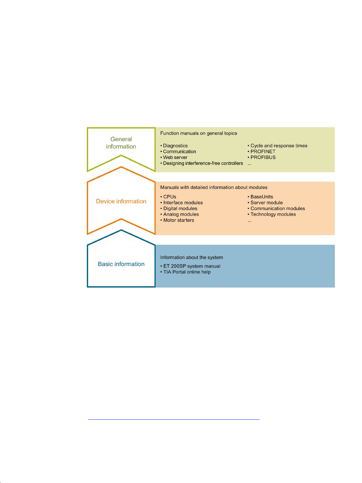
The documentation for the SIMATIC ET 200SP distributed I/O system is arranged into three
areas.
This arrangement enables you to access the specific content you require.
The System Manual and Getting Started describe in detail the configuration, installation,
wiring and commissioning of the SIMATIC ET 200SP distributed I/O system. The STEP 7
online help supports you in the configuration and programming.
Product manuals contain a compact description of the module-specific information, such as
properties, wiring diagrams, characteristics and technical specifications.
The function manuals contain detailed descriptions on general topics regarding the SIMATIC
ET 200SP distributed I/O system, e.g. diagnostics, communication, Web server, motion
control and OPC UA.
You can download the documentation free of charge from the Internet
(https://support.industry.siemens.com/cs/ww/en/view/109742709).
Changes and supplements to the manuals are documented in a Product Information.
ET 200SP Communication module CM 1xDALI (6ES7137-6CA00-0BU0)
Manual, 06/2019, A5E46959434-AA
7

Documentation guide
Manual Collection ET 200SP
"mySupport"
Application examples
You can download the product information free of charge from the Internet
(https://support.industry.siemens.com/cs/us/en/view/73021864).
The Manual Collection contains the complete documentation on the SIMATIC ET 200SP
distributed I/O system gathered together in one file.
You can find the Manual Collection on the Internet
(https://support.industry.siemens.com/cs/ww/en/view/84133942).
With "mySupport", your personal workspace, you make the most of your Industry Online
Support.
In "mySupport" you can store filters, favorites and tags, request CAx data and put together
your personal library in the Documentation area. Furthermore, your data is automatically
filled into support requests and you always have an overview of your current requests.
You need to register once to use the full functionality of "mySupport".
You can find "mySupport" in the Internet (https://support.industry.siemens.com/My/ww/en).
The application examples support you with various tools and examples for solving your
automation tasks. Solutions are shown in interplay with multiple components in the system separated from the focus in individual products.
You can find the application examples on the Internet
(https://support.industry.siemens.com/sc/ww/en/sc/2054).
ET 200SP Communication module CM 1xDALI (6ES7137-6CA00-0BU0)
8 Manual, 06/2019, A5E46959434-AA
2
2.1
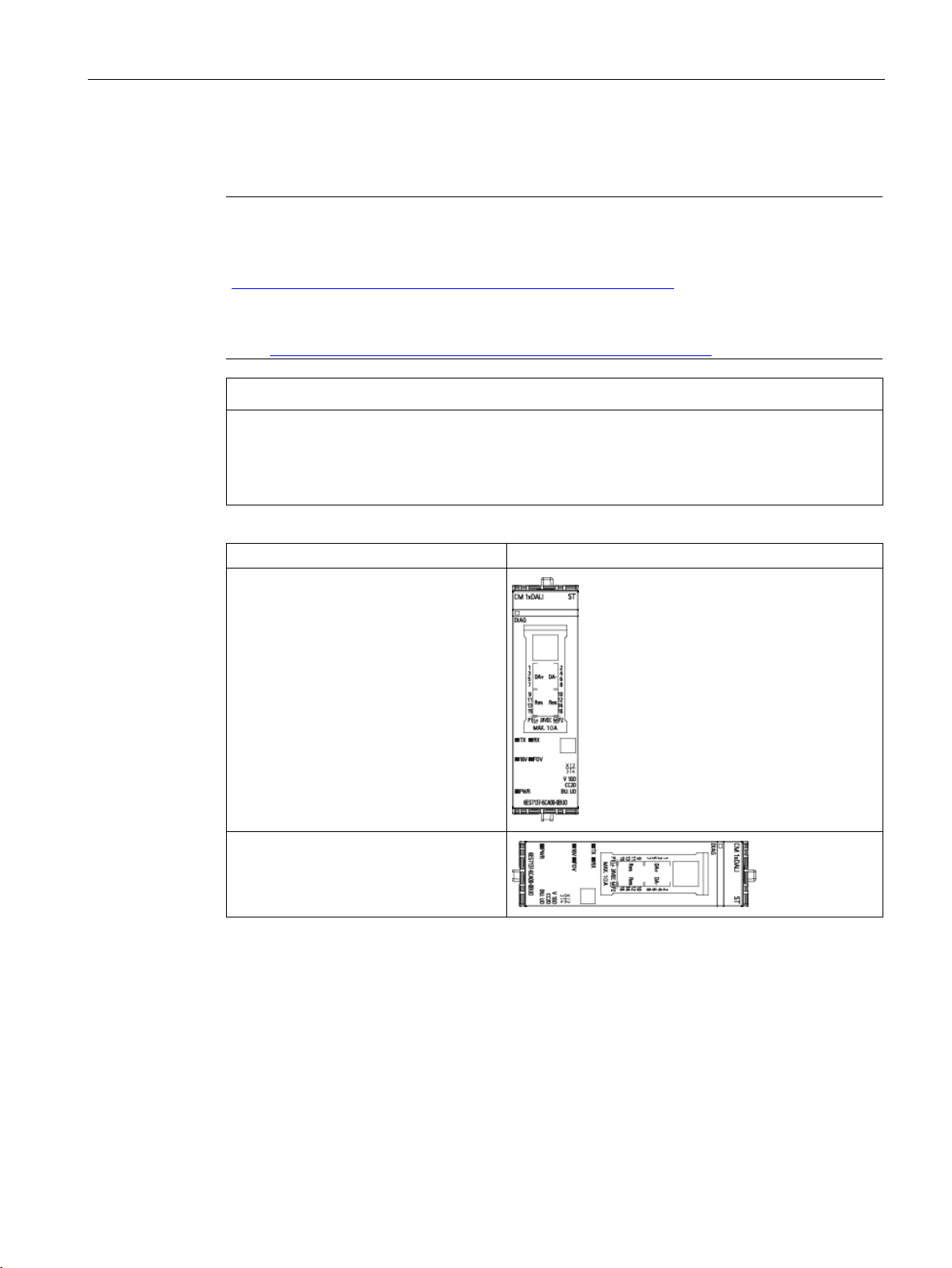
Properties
Article number
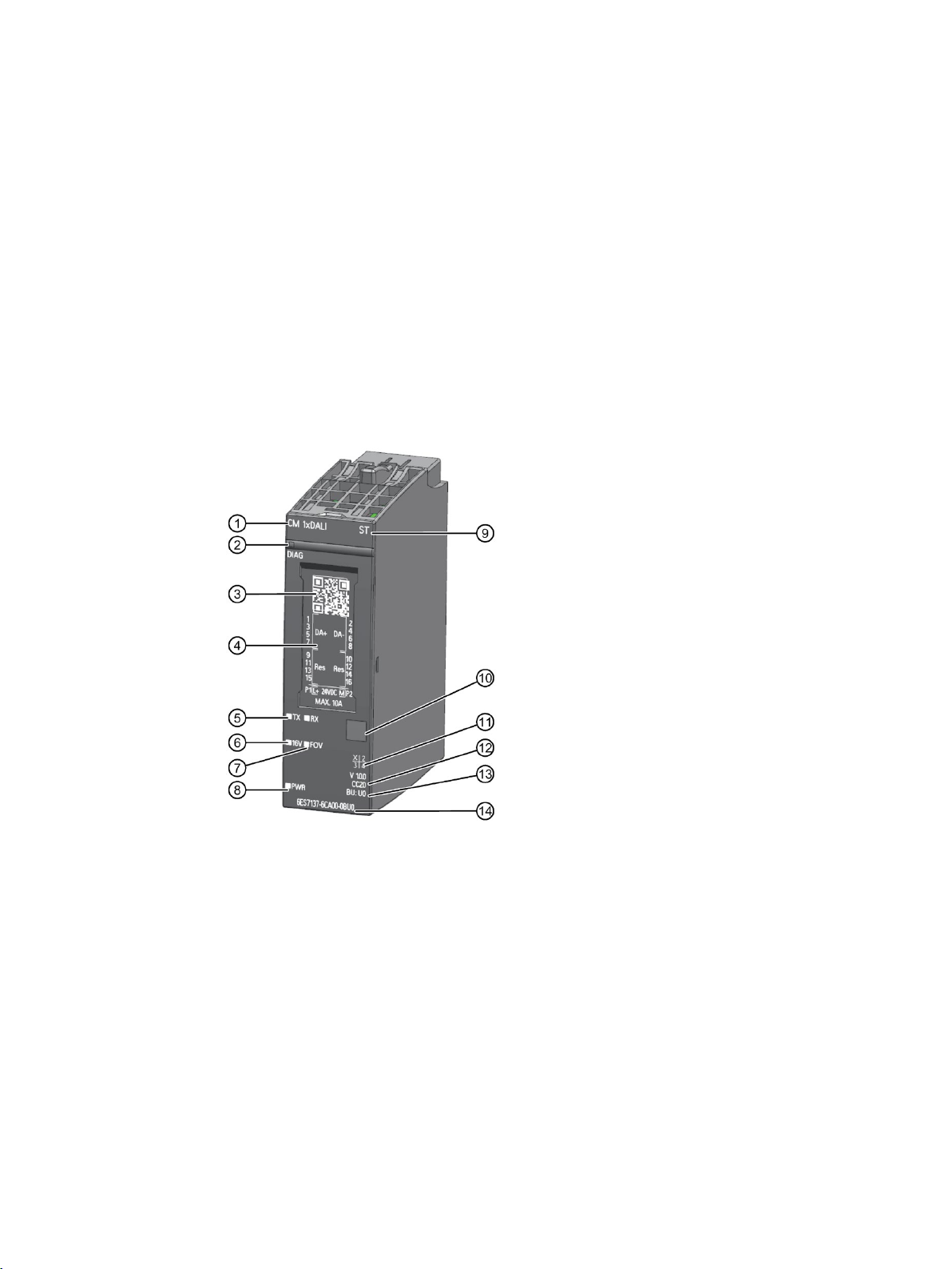
View of the module
①
Module type and name
⑧
LED for the supply voltage
②
LED for diagnostics
⑨
Function class
③
2D matrix code
⑩
Color coding module type
④
Wiring diagram
⑪
Function and firmware version
⑤
receiving status
⑫
⑥
bus power supply
⑬
⑦
on DALI bus
⑭
6ES7137-6CA00-0BU0
ET 200SP Communication module CM 1xDALI (6ES7137-6CA00-0BU0)
Manual, 06/2019, A5E46959434-AA
LEDs for transmitting and
LED for integrated DALI
LED for fault over voltage
Figure 2-1 View of the CM 1xDALI (without the BaseUnit)
Color code for color-coded labels
BU type
Article number
9

Product overview
Properties
2.1 Properties
The CM 1xDALI connects one DALI bus to the automation system and has the following
properties:
● Technical properties:
– DALI application controller (Multi-master)
– 1xDALI bus with 4 pairs DALI+ and DALI- terminals (non-polarity)
– 64 DALI control gears
– 63 DALI input devices
– 16 groups
– 16 scenes
– Integrated DALI bus power supply (can be disabled (Page 21))
– Supports external DALI power supply when you disable the integrated DALI power
supply
– DALI bus short circuit diagnostic behavior (Page 111)
– DALI bus fault over voltage protection which can protect DALI bus against accidental
connection of the main voltage (up to 250 V AC)
– Compliant with IEC 62386-101,103
– Support of device types according to IEC 62386- 201, 202, 203, 204, 205, 205, 206,
207, 208, 209 and others as generic type
– Support of input device types according to IEC 62386-301, 302, 303, 304
● Supported system functions:
– Firmware update
– Diagnostic
– I&M data (identification and maintenance data): I&M0 to I&M3
● Supported functions:
– Scan of the DALI bus and automatic assign of short addresses
– Integrated operation hours counting for each control gear
– Exchange two short addresses
– Commands to devices and to groups or as broadcast
– Control of groups and scenes
– Receive event messages from input devices
– Cyclic read of the status of the lamps
– CM 1xDALI can receive messages from sensors (multi-master). You can read these
messages from the command "DALI_CTRL". The other commands and queries to or
from DALI devices are called by the user program.
ET 200SP Communication module CM 1xDALI (6ES7137-6CA00-0BU0)
10 Manual, 06/2019, A5E46959434-AA

Product overview
CM 1xDALI Functionality
2.1 Properties
● Supported control gear types and input device types:
– Fluorescent (control gear type 00)
– Emergency lamp (control gear type 01)
– Discharge lamp (control gear type 02)
– Halogen (control gear type 03)
– Incandescent (control gear type 04)
– Voltage converter (control gear type 05)
– LED (control gear type 06)
– Switch function (control gear type 07)
– Color control (control gear type 08)
– Push button (input device type 01)
– Absolute input device (input device type 02)
– Occupancy sensor (input device type 03)
– Light sensor (input device type 04)
– Other types by generic commands
● CM 1xDALI controls the DALI bus and holds the parameters of the DALI devices. The
parameters are stored in the module even if power is off. The parameters can be read
from the CPU and deployed to the devices. There can be connected more than 64 sensor
instances in 1 DALI bus, but a maximum of 64 instance data sets can be stored in the
module.
● CM 1xDALI sends all received CPU commands from the CPU to the DALI bus, more
complex CPU commands (like setting parameters) are split into several DALI commands
by the module.
● CM 1xDALI has an operating hour counter for every device that can be read and set from
the CPU.
● If necessary, the module can scan the bus and assign short addresses to a newly
installed device on DALI bus with one command.
● CM 1xDALI queries the status of the devices cyclically, this action is called "background
detection". The CM 1xDALI periodically sends DALI commands to query the status of all
the devices on the bus and stores the information in the module. The query period can be
set by module parameters. The program blocks of the CPU have a higher priority when
accessing the DALI bus. If the program blocks of the CPU continuously access the DALI
bus, the background detection may be blocked. The background detection can detect the
following results:
– Whether each DALI device has a short address
– For control gear: the information of basic status, control gear type and extended status
– For sensor: the information of device status, number of instances and type of each
instance
ET 200SP Communication module CM 1xDALI (6ES7137-6CA00-0BU0)
Manual, 06/2019, A5E46959434-AA
11

Product overview
2.2
Compatibility
Connection to the system
Supported DALI devices
Library
2.2 Compatibility
Through BaseUnit type U0, you can assemble a CM 1xDALI to the CPU, open controller, or
IM of the ET 200SP distributed I/O system.
You can only use the input device which meets the standard of DALI-2, IEC 62386-103.
You can only use the control gear which meets the standard of DALI-1 or DALI-2. But on
DALI-1 control gears, you cannot use the new functionalities which are added in DALI-2
standard.
The CM 1xDALI library is compatible with the S7-1500 based CPUs (CPU 15xx).
ET 200SP Communication module CM 1xDALI (6ES7137-6CA00-0BU0)
12 Manual, 06/2019, A5E46959434-AA
3
3.1
Important notes on using the device
WARNING
Notes on use in hazardous areas according to ATEX / IECEx
WARNING
Requirement for the installing enclosure
WARNING
Provision against transient disturbances
WARNING
Hazardous location
The equipment is designed for operation with Safety Extra-Low Voltage (SELV) or
Protective Extra-Low Voltage (PELV).
This means that electrical circuit in which the voltage cannot exceed 30 V AC (RMS), 42.4
V AC peak or 60 V DC under NORMAL CONDITIONS and CONDITIONS OF A SINGLE
FAULT, including ground faults in other circuits.
The modules shall be installed in a suitable enclosure providing a degree of protection of at
least IP54 according to EN 60079-15, taking into account the environmental conditions
under which the equipment will be used.
Provisions shall be made to prevent the rated voltage from being exceeded by transient
disturbances of more than 119 V.
The equipment shall only be used in an area of not more than pollution degree 2, as
defined in EN 60664-1.
ET 200SP Communication module CM 1xDALI (6ES7137-6CA00-0BU0)
Manual, 06/2019, A5E46959434-AA
13
Wiring
General notices on use in hazardous areas according to FM
WARNING
Requirement for the installing enclosure
WARNING
Risk of burn injury
WARNING
Explosion hazard
WARNING
Cable
WARNING
Hazardous location
3.1 Important notes on using the device
If the equipment is installed within an ultimate enclosure, the inner service temperature of
the enclosure corresponds to the ambient temperature of the module.
If a device is operated in an ambient temperature of more than 50 °C, the temperature of
the device housing may be higher than 70 °C. The device must therefore be installed so
that it is only accessible to service personnel or users that are aware of the reason for
restricted access and the required safety measures at an ambient temperature higher than
50 °C.
Do not disconnect equipment unless power has been switched off or the area is known to
be non-hazardous.
The equipment is intended to be installed within an enclosure/control cabinet. The inner
service temperature of the enclosure/control cabinet corresponds to the ambient
temperature of the module. Use cables with a maximum permitted operating temperature of
at least 30 °C higher than the maximum ambient temperature.
The equipment shall only be used in an area of not more than pollution degree 2.
ET 200SP Communication module CM 1xDALI (6ES7137-6CA00-0BU0)
14 Manual, 06/2019, A5E46959434-AA
Wiring
3.2
Installing position
Note
When installing and connecting up the CM 1xDALI, refer to the instructions in the system
manual SIMATIC ET 200SP Distributed I/O system
(
document "Use of subassemblies/modules in a Zone 2 Hazardous Area" that you will find on
the Internet at the following address:
Link: (
NOTICE
Installation location - Dependency of the temperature range
Installation position
Installation position of the CM 1xDALI
3.2 Installing position
https://support.industry.siemens.com/cs/ww/en/view/58649293) note the information in the
https://support.industry.siemens.com/cs/ww/en/view/78381013)
The upper and lower ventilation slits of CM 1xDALI cannot be covered, allowing adequate
ventilation. Above and below the module, there must be a clearance of 25 mm to allow air
to circulate and prevent overheating.
Horizontal installation of the CM 1xDALI
Vertical installation of the CM 1xDALI
ET 200SP Communication module CM 1xDALI (6ES7137-6CA00-0BU0)
Manual, 06/2019, A5E46959434-AA
15

Wiring
3.3
DALI bus cable
Requirement for DALI cable
Material
Cable length
Conductor cross section (Minimum)
< 100 m
0.5 mm2
> 150 m
1.5 mm2
Conductor cross section depending on the cable length
Note
It is not necessary to use special bus cables (twisted or shielded).
Maximum current permitted for integrated DALI power
Example
3.3 DALI bus cable
Pay attention to the following requirements when you set up a DALI system.
● The voltage drop between the DALI power supply and any DALI device on the DALI bus
must be less than 2 V.
● The cable length between DALI power supply and the DALI device should be less than
300 m. The recommend minimum-cross-section of the conductors depends on the cable
length.
Copper
100 m to 150 m 0.75 mm2
When use the integrated DALI power, the DALI bus load ∑ I
You can calculate the DALI bus load with the following formula:
∑ I
= I
DALI
∑ I
: Load of the DALI supply including all extension terminals
DALI
I
: Load of the first device on DALI bus
DALI_1
n: Total number of the devices on DALI bus
You need to set up a DALI system with some control gears and sensors. At first, you add 64
control gears whose respective current consumption is 2 mA. Then you need to add a kind
of sensor whose respective current consumption is 5 mA.
The number of sensor you can add is:
(160 mA - 64 x 2 mA) / 5 mA = 6.4
So the maximum number of this kind sensor you can add in this DALI system is 6.
DALI_1
+ I
DALI_2
+ I
DALI_3
+ ... + I
DALI_n
cannot exceeds 160 mA.
DALI
ET 200SP Communication module CM 1xDALI (6ES7137-6CA00-0BU0)
16 Manual, 06/2019, A5E46959434-AA

Wiring
DALI bus topology
NOTICE
Important notes on setting up DALI system
3.3 DALI bus cable
CM 1xDALI is a gateway between automation system and DALI system. At the CPU side,
CM 1xDALI works as a communication module and gateway to the system. At DALI side,
CM 1xDALI works as an application controller. You can use line, tree, star or mixed
structures to set up the DALI system.
• Do not use ring structure to set up a DALI system.
• Use the input devices which fulfill the DALI-2 standard.
• CM 1xDALI module cannot work until CPU and IM are ready. Make sure CPUs are
ready before you start up the DALI communication.
The following figure shows an example of a DALI topology containing 4 DALI systems.
Figure 3-1 DALI Topology
ET 200SP Communication module CM 1xDALI (6ES7137-6CA00-0BU0)
Manual, 06/2019, A5E46959434-AA
17

Wiring
3.4
Block diagram
Requirements
BaseUnit
3.4 Block diagram
For connecting, you require a BaseUnit:
● Type U0, Light color BaseUnit, article number 6ES7193-6BP00-0DU0
● Type U0, Dark color BaseUnit, article number 6ES7193-6BP00-0BU0
The BaseUnit is not included in the scope of delivery of the module and must be ordered
separately.
You can find an overview of the BaseUnits that you can use with the technology module in
the product information for the documentation of the ET 200SP distributed I/O system
(https://support.industry.siemens.com/cs/ww/en/view/73021864).
You can find information about selecting a suitable BaseUnit in the ET 200SP Distributed I/O
System (https://support.industry.siemens.com/cs/ww/en/view/58649293) system manual and
ET 200SP BaseUnits (https://support.industry.siemens.com/cs/ww/en/view/59753521)
manual.
You can find information on wiring the BaseUnit, connecting cable shields, etc. in the
Connecting section of the ET 200SP Distributed I/O System
(https://support.industry.siemens.com/cs/ww/en/view/58649293) system manual.
ET 200SP Communication module CM 1xDALI (6ES7137-6CA00-0BU0)
18 Manual, 06/2019, A5E46959434-AA
Wiring
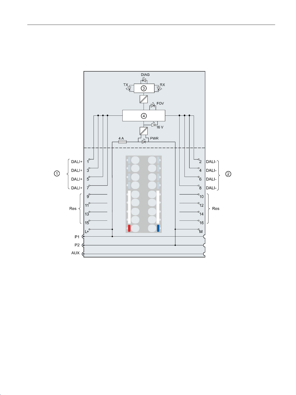
Block diagram
①
DALI+ connection
TX
Transmit LED (green)
②
DALI- connection
RX
Receive LED (green)
③
Backplane bus interface
FOV
Fault over voltage LED (red)
④
DALI driver electronics
PWR
POWER LED (green)
DIAG
Error or Diagnostics LED (green, red)
L+
24 VDC supply voltage
Connection to the left interrupted (light BaseUnit)
M
Ground
3.4 Block diagram
The following figure shows the block diagram and the terminal assignment of the
CM 1xDALI.
P1, P2, AUX Internal self-configuring voltage buses
Connection to the left (dark BaseUnit)
Figure 3-2 Wiring and block diagram for CM 1xDALI
ET 200SP Communication module CM 1xDALI (6ES7137-6CA00-0BU0)
Manual, 06/2019, A5E46959434-AA
19

Wiring
L+/M supply voltage
3.4 Block diagram
You connect the supply voltage (DC 24 V) to terminals L+ and M on a light BaseUnit. For a
dark BaseUnit, it uses the supply voltage of the module on its left. An internal protection
circuit protects the CM 1xDALI from reverse polarity of the supply voltage. The CM 1xDALI
monitors whether the supply voltage is connected.
ET 200SP Communication module CM 1xDALI (6ES7137-6CA00-0BU0)
20 Manual, 06/2019, A5E46959434-AA

4
4.1
Parameter assignment
Introduction
4.2
CM 1xDALI Module Parameters
Module Parameters
Module Parameters
Module Parameters
Description
Value range
Default
value
Configuration in
RUN
Basic parameter
You configure and assign the parameters of the communication module with STEP 7 V15.1
or later versions.
In the CM 1xDALI project, you assign the parameters in the device view of STEP 7 and in
the properties tab of the communication module DALI.
Each CM 1xDALI has the following DALI parameters in
your request, you can configure any of these parameters.
The following table shows the module parameters for the CM 1xDALI.
Table 4- 1 Module Parameters
Enable integrated
DALI bus power supply
Enable DALI Application Controller
Enable or disable the DALI bus power supply.
• Enable: Use the integrated DALI bus power in the CM
1xDALI.
• Disable: Do not use the integrated DALI bus power in
the CM 1xDALI.
Enable or disable DALI Application Controller.
• Enable: The CM 1xDALI can send any forward frame
or receive any backward frame to the DALI bus.
• Disable: The CM 1xDALI cannot send any forward
frame or receive any backward frame to the DALI bus.
• Enable
• Disable
• Enable
• Disable
Enable Yes
Enable Yes
. According to
ET 200SP Communication module CM 1xDALI (6ES7137-6CA00-0BU0)
Manual, 06/2019, A5E46959434-AA
21

Parameters
Module Parameters
Description
Value range
Default
value
Configuration in
RUN
Diagnostics
Period
saved in the DALI device update during every detection.
4.2 CM 1xDALI Module Parameters
Diagnostics: Over
voltage on DALI bus
Diagnostics: Short
circuit on DALI bus
Background detection
period (s)
Enable or disable the diagnostic message on DALI bus.
• Enable: When the DALI bus is connected to a fault
over voltage (FOV) by mistake, the CM 1xDALI reports an error of over voltage and the FOV LED
(Page 109) is on.
• Disable: When the DALI bus is connected to a fault
over voltage by mistake, only the FOV LED is on.
Monitor the short circuit on DALI bus. This function is only
available when the integrated DALI bus power supply is
enabled:
• Enable: When a short circuit occurs on the DALI bus,
the module reports a diagnostic error and shuts down
the bus power.
• Disable: When a short circuit occurs on the DALI bus,
the module only shuts down the bus power.
The CM 1xDALI periodically sends DALI commands to
query the status of all the devices on the bus and stores
the information in the module. As a result, the status that
is saved in CM 1xDALI cannot be updated in time to get
the latest status information in the CM 1xDALI. The program blocks of the CPU have a higher priority when accessing the DALI bus. If the program blocks of the CPU
continuously access the DALI bus, the background detection may be blocked. The background detection can detect the following results:
• Whether each DALI device has a short address
• For control gear: the information of basic status, con-
trol gear type and extended status
• For sensor: the information of device status, number
of instances and type of each instance
You can set the frequency of the detection. The status
• Enable
• Disable
• Enable
• Disable
60 to 3600
(second)
Enable Yes
Disable Yes
60 (second)
Yes
ET 200SP Communication module CM 1xDALI (6ES7137-6CA00-0BU0)
22 Manual, 06/2019, A5E46959434-AA

5
5.1
CM 1xDALI data storage model
CM 1xDALI data storage model
CM 1xDALI library is a SIMATIC CPU program library. You use the CM 1xDALI library to
program for the CM 1xDALI. It helps you easily access CM 1xDALI from the SIMATIC CPU.
CM 1xDALI library can be used on S7-1500 based CPUs (CPU 15xx).
CM 1xDALI library contains several CM 1xDALI function blocks (FB) in the STEP 7. The CM
1xDALI function blocks are collected in several functions groups, such as Addressing
function blocks (Page 32), Control gear dimming function blocks (Page 40), Diagnostic
function blocks (Page 52) and Configuration function blocks (Page 67).
Download the CM 1xDALI library from the Internet
(https://support.industry.siemens.com/cs/ww/en/view/109767048). For more information
about using libraries, refer to STEP 7 online help.
A DALI device can be a control gear or input device. The term "sensor" refers to the input
device in this documentation.
Each of the CM 1xDALI and DALI devices has its own database to store status and address
information.
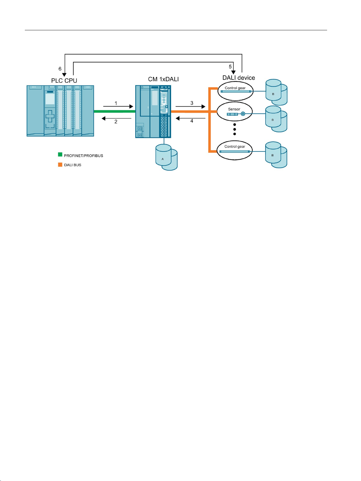
The following figure shows the CM 1xDALI data storage model and data flow.
ET 200SP Communication module CM 1xDALI (6ES7137-6CA00-0BU0)
Manual, 06/2019, A5E46959434-AA
23
Programming
A
CM 1xDALI Database
B
DALI device Database
DALI_ECG_SET_OPHOUR (Page 59) to set the operating hour of control gear in CM 1xDALI.
DALI_DEV_QUERY_ADDR
address status and device status which are saved in CM 1xDALI.
DALI_DEV_DOWNLOAD
the configuration parameters stored in the CM 1xDALI to the DALI device.
ries the device status of each DALI device by background detection.
DALI_SENSOR_SET_INST_PARAM
send the instance configuration parameters to the DALI device
DALI_DEV_GTIN
trade item number from the DALI device.
5.1 CM 1xDALI data storage model
1 CPU sends data to CM 1xDALI, and CM 1xDALI stores the data. For example, the CPU uses
2 CPU receives data from CM 1xDALI. For example, the CPU uses
3 CM 1xDALI sends data to the DALI device. For example, the CPU uses
4 CM 1xDALI receives data from the DALI device, and stores the data in CM 1xDALI. For example, the CM 1xDALI que-
5 CPU sends data to the DALI device. For example, the CPU uses
6 CPU receives data from DALI device. For example, the CPU uses
Figure 5-1 CM 1xDALI data storage model and data flow
(Page 52) to query the global
(Page 37) to obtain the
(Page 102) to deploy
(Page 97) to
ET 200SP Communication module CM 1xDALI (6ES7137-6CA00-0BU0)
24 Manual, 06/2019, A5E46959434-AA

Programming
Parameters
Storage location
Read-
only
Description
CM
1xDALI
DALI
devices
DALI devices.
of control gears
5.2
General information for programming
About function block (FB)
DALI_CTRL
DALI_ECG_SWITCH_DIM
About DALI_CTRL
DALI_CTRL
DALI_CTRL
DALI_CTRL
DALI_CTRL
DALI_CTRL
5.2 General information for programming
For the detailed parameter information on CM 1xDALI database and DALI device database,
refer to the following table.
Table 5- 1 Description for database parameters
DALI device
status
Address status ✓ ✓ The address status of DALI device on the bus. CM 1xDALI cyclic queries
Configuration
parameters
Operating hour
✓ ✓ ✓ The basic status and extended status of control gears, and device status
of sensors.
all the address status of DALI devices on the bus through the background detection, and detects the following results:
• Whether each DALI device has a short address
• For control gear: the information of basic status, control gear type
and extended status
• For sensor: the information of device status, number of instances and
type of each instance
✓ ✓ The basic parameters, extended parameters, group and scene parame-
ters of control gears and device parameters, instance parameters of
sensors. The CM 1xDALI does not store the read-only parameters of the
✓ The CM 1xDALI stores the operating hour of configured control gears.
The following general information is useful for programming a DALI application:
ET 200SP Communication module CM 1xDALI (6ES7137-6CA00-0BU0)
Manual, 06/2019, A5E46959434-AA
● All the FBs in CM 1xDALI library are asynchronous instructions. It is recommended to use
the FBs in the same cyclic organization block (OB).
● Most of the FBs in the CM 1xDALI library are triggered by a rising edge, except for
(Page 26)and
(Page 42).
● If you call several FBs at the same time, they are queued. You can check the output
parameters in each FB.
●
(Page 26) is the basic FB of CM 1xDALI.
must be called in a
cyclic OB, and be executed in every cycle. Do not use it in an interrupt OB.
● Each CM 1xDALI works with only one instance of
● Specify the hardware ID of connected CM 1xDALI at the
connect the
DB with the other FBs through the InOut parameter of CM_DALI.
FB.
FB, and then
25

Programming
About output parameter
DALI_ECG_SWITCH_DIM
5.3
System function blocks
5.3.1
DALI_CTRL
Description
DALI_CTRL
DALI_CTRL
DALI_CTRL
DALI_CTRL
DALI_CTRL
DALI_CTRL
5.3 System function blocks
● The outputs of the FBs are kept when the processing of job is done:
– For the FBs with an input of CANCEL, only when both the trigger and input of
CANCEL turn to zero, their output is reset.
– For the FBs without the input CANCEL, when the trigger turns to zero, the output of
these FBs is reset.
● If the triggering input is reset before the FB has finished, the output parameters are set at
least for one cycle.
● The output of
the inputs ON_UP or OFF_DOWN; the output of this FB will not be reset all of the time.
● Most of the FBs have the following output parameters:
– BUSY: Shows whether the FB is being committed. When BUSY = 1, the FB is
triggered but not finished yet.
– ACTIVE: Shows whether the FB is being executed. When ACTIVE = 1, the FB is
communicating with the CM 1xDALI.
– DONE: Shows whether the FB is executed without errors. When DONE = 1, the FB is
executed without any error. You can check the result of execution in the output of this
FB.
– ERROR: Shows whether an error occurs during the process. When ERROR = 1, the
FB is stopped with some errors. You can check the error code in STATUS of this FB.
– STATUS: Shows the FB progress or detailed error code. When ERROR = 0, STATUS
shows the FB progress; when ERROR = 1, STATUS shows the detailed error code.
System function blocks are the basic function blocks of the CM 1xDALI, and they are used
for sending all DALI commands.
(Page 42) can be triggered by a positive level at
the other DALI function blocks can communicate with the CM 1xDALI.
●
cyclic OB, and be executed in every cycle. Do not use it in an interrupt OB.
● Each CM 1xDALI works with only one instance of
● Specify the hardware ID of connected CM 1xDALI at the
connect the
ET 200SP Communication module CM 1xDALI (6ES7137-6CA00-0BU0)
26 Manual, 06/2019, A5E46959434-AA
is used as the interface for the CM 1xDALI. Through this function block, all of
is the basic function block of CM 1xDALI.
DB with the other FBs through the InOut parameter of CM_DALI.
must be called in a
FB.
FB, and then

Programming
Parameter
Parameter
Decla-
ration
Data
type
Memory
area
Description
Constant
Constant
reset to 0.
following section "Parameter CM_STATUS".
5.3 System function blocks
● The FB receives and reports the event messages which are sent be the DALI-2 input
devices.
● When Bit 1 or Bit 2 of the CM_STATUS show "1", all the other DALI function blocks
cannot be executed. You can choose any of the following actions to resume the status of
CM 1xDALI.
– Set the input CM_RESET to 1.
– Send the DALI command "STOP QUIESCENT MODE" or "ENABLE APPLICATION
CONTROLLER" (refer to IEC 62386-103) to the CM 1xDALI through other DALI
application controllers.
● A defined set of messages and their content are shown at the inputs EVENT_MSG,
EVENT_SCHEME, EVENT_SRC_1, EVENT_SRC_2 and EVENT_INFO.
● Other generic event messages are shown at the outputs RSV_MSG, RSV_MSG_LEN
and RSV_MSG_VAL. The content is shown without interpretation at the output
RSV_MSG_VAL.
The following table shows the parameters of the function block.
HW_ID Input HW_IO I, Q, M,
D, L or
CM_RES
ET
CONN_E
RR
CM_STAT
US
EVENT_M
SG
Output
BOOL I, Q, M,
D, L or
BOOL I, Q, M,
D, L
DWORD I, Q, M,
D, L
BOOL I, Q, M,
D, L
The hardware identifier of the CM 1xDALI
Stop quiescent mode and re-enable the DALI application controller upon a
raising edge. After this action, Bit 1 and Bit 2 of the CM_STATUS will be
The status of CPU communication with CM 1xDALI:
• CONN_ERR = 0: No error when the CPU communicates with CM
1xDALI.
• CONN_ERR = 1: Error occurs when the CPU communicates with CM
1xDALI.
Indicate the status of the CM 1xDALI:
16#00000000: The status of the CM 1xDALI is OK.
For the detailed explanation for each Bit of the CM_STATUS, refer to the
The status of the sensor event. When the CM 1xDALI receives a sensor
event, the EVENT_MSG remains true for one cycle:
• EVENT_MSG = 0: No sensor event
• EVENT_MSG = 1: A sensor event is received.
ET 200SP Communication module CM 1xDALI (6ES7137-6CA00-0BU0)
Manual, 06/2019, A5E46959434-AA
27

Programming
Parameter
Decla-
ration
Data
type
Memory
area
Description
mation
dress
group
mation
number
type
type
dress 2
following section "Parameter EVENT_INFO".
G_LEN
D, L
G_VAL
D, L
For a valid device group, group of EVENT_SRC_1 indicates the lowest group; otherwise it shows "16#FF".
erwise, it shows "16#FF".
Parameter CM_STATUS
Bit
Explanation of status
Bit 0
The CM 1xDALI is initializing.
Bit 1
The CM 1xDALI is set to quiescent mode by DALI command "START QUIESCENT MODE".
Bit 2
The CM 1xDALI is disabled by DALI command "DISABLE APPLICATION CONTROLLER".3
Bit 3
The application controller is disabled by module parameters.4
Bit 4
The DALI bus is over voltage.
Bit 5
Missing Voltage (MV)5 of module input
Bit 6
The DALI bus is short-circuited.
bus.
5.3 System function blocks
EVENT_S
CHEME
EVENT_S
RC_1
EVENT_S
RC_2
EVENT_I
NFO
RSV_MS
G
RSV_MS
USInt I, Q, M,
D, L
USInt I, Q, M,
D, L
USInt I, Q, M,
D, L
WORD I, Q, M,
D, L
BOOL I, Q, M,
D, L
USInt I, Q, M,
Event characterization that identifies the source of the event:
• 0~4: Normal event message
• 255: Power cycle event
Scheme of the
event
First event
source infor-
Second event
source infor-
When EVENT_SCHEME ≤ 4, the lower 10 bits of EVENT_INFO indicate the
event data.
When EVENT_SCHEME = 255, EVENT_INFO shows "16#0000".
For the detailed meaning of EVENT_INFO in DALI standard, refer to the
The status of the reserved message. When the CM 1xDALI receives a reserved message, the RSV_MSG remains true for one cycle:
• RSV_MSG = 0: No reserved message
• RSV_MSG = 1: A reserved message is received.
The bit length of the reserved message
0 1 2 3 4 255
Instance
type
Instance
number
Short
address
Instance
type
Short
ad-
Instance
Device
group
Instance
Instance
Instance
Group 1
Short
ad-
RSV_MS
1
2
For a valid short address, short address of EVENT_SRC_2 indicates the short address of the device; oth-
DWORD I, Q, M,
The bit stream of the reserved message
Each Bit of the CM_STATUS indicates the different status:
Bit 7 Integrated DALI bus power is disabled in CM 1xDALI, and there is no external DALI bus power on DALI
ET 200SP Communication module CM 1xDALI (6ES7137-6CA00-0BU0)
28 Manual, 06/2019, A5E46959434-AA

Programming
Bit
Explanation of status
Bit 8
Several error frames on the bus.
application controllers.
frame or response frame to the bus.
When the input voltage 24 VDC is lower than 16V±1V, the PWR LED changes from green to off.
Parameter EVENT_INFO
Event information
Event name
Description
2#00_0000_0000
Button released
The button is released.
2#00_0000_0001
Button pressed
The button is pressed.
2#00_0000_0010
Short press 6
Press the button and release quickly.
2#00_0000_0101
Double press
Press the button twice in rapid succession.
2#00_0000_1001
Long press start 6
Press the button and hold for longer than the T
short
.
regular intervals as long as the condition holds.
2#00_0000_1100
Long press stop 6
The button is released after a long press.
2#00_0000_1111
Button stuck
The button is pressed for a very long time and is assumed stuck.
6
To configure instance related parameters for push button, refer to
DALI_SENSOR_SET_INST_PARAM (Page 97).
Event information
Event name
description
to the DALI Device Manual from the manufacturer for details.
Event information
Event name
description
2#00_0000_***0
No movement
Does not detect movement.
2#00_0000_***1
Movement
Detects movement.
2#00_0000_*00*
Vacant
The area is vacant.
long as the vacant condition holds.
5.3 System function blocks
Bit 9 to Bit 31 Reserved
3
When the module is disabled by other DALI application controllers, the CM 1xDALI cannot send out any
forward frame (16-bits or 24-bits) to the bus, but it can send out the response frame (8-bits) to other DALI
4
When the module is disabled by the module parameters, the CM 1xDALI cannot send out any forward
5
EVENT_INFO of push button (instance type 1)
2#00_0000_1011 Long press repeat 6 The button is still pressed after a long press. The event occurs at
2#00_0000_1110 Button free The button is restored from getting stuck.
Others Reserved
EVENT_INFO of absolute input devices (instance type 2)
positionEvent
Position report A position report contains the actual position of the sensor. Refer
EVENT_INFO of occupancy sensor (instance type 3)
2#00_0000_*10* Still vacant The area is still vacant. The event occurs at regular intervals as
ET 200SP Communication module CM 1xDALI (6ES7137-6CA00-0BU0)
Manual, 06/2019, A5E46959434-AA
29
 Loading...