

Siemens SIMATIC ET 200pro, SIMATIC ET 200pro FC-2 Original Instructions Manual


SIMATIC ET 200pro FC-2 converter
___________________
___________________
___________________
___________________
___________________
___________________
___________________
___________________
___________________
___________________
___________________
___________________
___________________
SIMATIC
SIMATIC ET 200pro FC-2
SIMATIC ET 200pro FC-2 converter
Operating Instructions
Edition 04/2015, firmware version V4.7.3
Original instructions
04/2015, FW V4.7.3
A5E34257324B AB
Fundamental safety
instructions
1
Introduction
2
Description
3
Installation
4
Configure the hardware
5
Commissioning
6
Configure the fieldbus
7
Setting functions
8
Backing up data and series
commissioning
9
Repair
10
Alarms, faults and system
messages
11
Technical data
12
Appendix
A

Siemens AG
Division Digital Factory
Postfach 48 48
90026 NÜRNBERG
GERMANY
Order number: (null)
Ⓟ
Copyright © Siemens AG 2014 - 2015.
All rights reserved
Legal information
Warning notice system
DANGER
indicates that death or severe personal injury will result if proper precautions are not taken.
WARNING
indicates that death or severe personal injury may result if proper precautions are not taken.
CAUTION
indicates that minor personal injury can result if proper precautions are not taken.
NOTICE
indicates that property damage can result if proper precautions are not taken.
Qualified Personnel
personnel qualified
Proper use of Siemens products
WARNING
Siemens products may only be used for the applications described in the catalog and in the relevant technical
equired to ensure that the products operate safely and without any problems. The permissible
ambient conditions must be complied with. The information in the relevant documentation must be observed.
Trademarks
Disclaimer of Liability
This manual contains notices you have to observe in order to ensure your personal safety, as well as to prevent
damage to property. The notices referring to your personal safety are highlighted in the manual by a safety alert
symbol, notices referring only to property damage have no safety alert symbol. These notices shown below are
graded according to the degree of danger.
If more than one degree of danger is present, the warning notice representing the highest degree of danger will
be used. A notice warning of injury to persons with a safety alert symbol may also include a warning relating to
property damage.
The product/system described in this documentation may be operated only by
task in accordance with the relevant documentation, in particular its warning notices and safety instructions.
Qualified personnel are those who, based on their training and experience, are capable of identifying risks and
avoiding potential hazards when working with these products/systems.
Note the following:
documentation. If products and components from other manufacturers are used, these must be recommended
or approved by Siemens. Proper transport, storage, installation, assembly, commissioning, operation and
maintenance are r
All names identified by ® are registered trademarks of Siemens AG. The remaining trademarks in this publication
may be trademarks whose use by third parties for their own purposes could violate the rights of the owner.
We have reviewed the contents of this publication to ensure consistency with the hardware and software
described. Since variance cannot be precluded entirely, we cannot guarantee full consistency. However, the
information in this publication is reviewed regularly and any necessary corrections are included in subsequent
editions.
for the specific
07/2015 Subject to change

Table of contents
1 Fundamental safety instructions ............................................................................................................ 11
2 Introduction ........................................................................................................................................... 19
3 Description ............................................................................................................................................ 21
4 Installation ............................................................................................................................................ 29
1.1 General safety instructions ..................................................................................................... 11
1.2 Safety instructions for electromagnetic fields (EMF) .............................................................. 15
1.3 Handling electrostatic sensitive devices (ESD) ...................................................................... 15
1.4 Industrial security .................................................................................................................... 16
1.5 Residual risks of power drive systems .................................................................................... 16
2.1 About this manual ................................................................................................................... 19
2.2 Guide through this manual ...................................................................................................... 20
3.1 Components for assembling a frequency converter ............................................................... 21
3.2 Spare parts and accessories .................................................................................................. 24
3.3 Motor series that are supported .............................................................................................. 26
3.4 Tools to commission the inverter ............................................................................................ 27
4.1 Prerequisites and maximum expansion .................................................................................. 29
4.2 Mounting the racks .................................................................................................................. 30
4.3 Mounting the interface module ............................................................................................... 34
4.4 Mounting the bus module ....................................................................................................... 35
4.5 Mounting the terminating module ........................................................................................... 36
4.6 Mounting the connection module for IM154 ........................................................................... 37
4.7 Mounting the converter ........................................................................................................... 39
4.8 Interfaces ................................................................................................................................ 42
4.8.1 Communication interfaces ...................................................................................................... 42
4.8.1.1 Optical interface ...................................................................................................................... 42
4.8.1.2 Fieldbus interface (backplane bus) ......................................................................................... 43
4.8.1.3 Memory card reader ................................................................................................................ 43
4.8.1.4 Mini USB interface .................................................................................................................. 44
4.8.2 Temperature sensor interface ................................................................................................. 45
4.8.3 Interface to the motor holding brake ....................................................................................... 45
4.9 Wiring the ET200pro system .................................................................................................. 45
4.10 Mounting ET 200pro FC-2 fail-safe devices ........................................................................... 49
4.10.1 Mounting the bus module and the repair switch ..................................................................... 50
4.10.2 Mounting the module for the F-Swtich .................................................................................... 50
SIMATIC ET 200pro FC-2 converter
Operating Instructions, 04/2015, FW V4.7.3, A5E34257324B AB
5

Table of contents
5 Configure the hardware ......................................................................................................................... 53
6 Commissioning ..................................................................................................................................... 67
7 Configure the fieldbus ........................................................................................................................... 85
8 Setting functions ................................................................................................................................... 99
5.1 Integrating ET 200 frequency converters into automation systems with STEP 7 .................. 53
5.2 Install HSP or GSD ................................................................................................................ 54
5.2.1 Installation of a hardware support package (HSP) ................................................................ 54
5.2.2 Installation of a master device file (GSD) .............................................................................. 54
5.3 Configure the hardware in SIMATIC Manager ....................................................................... 55
5.3.1 Configure the inverter on PROFIBUS in SIMATIC Manager ................................................. 55
5.3.2 Configure the inverter on PROFINET in SIMATIC Manager ................................................. 58
5.3.3 Configure the inverter with Safety Integrated in SIMATIC Manager ...................................... 63
5.3.4 Enable the diagnostic alarm ................................................................................................... 66
6.1 Commissioning guidelines ..................................................................................................... 67
6.2 Preparing for commissioning ................................................................................................. 68
6.2.1 Factory setting of the inverter control..................................................................................... 69
6.2.2 Selecting the control mode .................................................................................................... 70
6.2.3 Defining additional requirements for the application .............................................................. 71
6.3 Restoring the factory setting .................................................................................................. 71
6.4 Resetting the safety function parameters to the factory setting ............................................. 72
6.5 Basic commissioning ............................................................................................................. 74
6.5.1 Basic commissioning with the IOP operator panel ................................................................ 74
6.5.2 Basic commissioning with STARTER .................................................................................... 77
6.5.2.1 Creating a project ................................................................................................................... 78
6.5.2.2 Transfer inverters connected via USB into the project .......................................................... 78
6.5.2.3 Go online and start the configuration wizards ........................................................................ 80
6.5.2.4 Carry-out basic commissioning .............................................................................................. 80
6.5.2.5 Identify motor data ................................................................................................................. 82
7.1 PROFIdrive profile for PROFIBUS and PROFINET .............................................................. 85
7.1.1 Cyclic communication ............................................................................................................ 85
7.1.1.1 Control and status word 1 ...................................................................................................... 86
7.1.1.2 Extend telegram ..................................................................................................................... 88
7.1.2 Acyclic communication ........................................................................................................... 89
7.2 PROFIenergy profile for PROFINET ...................................................................................... 94
7.2.1 General inverter behavior when in the PROFIenergy energy-saving mode .......................... 94
7.2.2 Settings and displays for PROFIenergy in the inverter .......................................................... 95
7.2.3 Control commands and status queries .................................................................................. 96
8.1 Overview of the inverter functions.......................................................................................... 99
8.2 Inverter control ..................................................................................................................... 101
8.3 Setpoints .............................................................................................................................. 102
8.3.1 Overview .............................................................................................................................. 102
8.3.2 Specifying the setpoint via the fieldbus ................................................................................ 103
8.3.3 Motorized potentiometer as setpoint source ........................................................................ 103
8.3.4 Fixed speed as setpoint source ........................................................................................... 105
SIMATIC ET 200pro FC-2 converter
6 Operating Instructions, 04/2015, FW V4.7.3, A5E34257324B AB

Table of contents
8.4 Setpoint calculation ............................................................................................................... 107
8.4.1 Overview of setpoint processing ........................................................................................... 107
8.4.2 Invert setpoint ....................................................................................................................... 108
8.4.3 Inhibit direction of rotation ..................................................................................................... 108
8.4.4 Skip frequency bands and minimum speed .......................................................................... 109
8.4.5 Speed limitation .................................................................................................................... 110
8.4.6 Ramp-function generator ...................................................................................................... 110
8.5 Motor control ......................................................................................................................... 115
8.5.1 V/f control .............................................................................................................................. 115
8.5.1.1 Characteristics of U/f control ................................................................................................. 116
8.5.1.2 Selecting the U/f characteristic ............................................................................................. 117
8.5.1.3 Optimizing motor starting ...................................................................................................... 118
8.5.2 Vector control ........................................................................................................................ 120
8.5.2.1 Overview ............................................................................................................................... 120
8.5.2.2 Select motor control .............................................................................................................. 121
8.5.2.3 Optimizing the speed controller ............................................................................................ 122
8.5.2.4 Friction characteristic ............................................................................................................ 124
8.5.2.5 Moment of inertia estimator .................................................................................................. 126
8.6 Protection and monitoring functions ..................................................................................... 132
8.6.1 Inverter temperature monitoring ........................................................................................... 132
8.6.2 Monitor the motor temperature via a temperature sensor .................................................... 135
8.6.3 Protecting the motor by calculating the motor temperature .................................................. 138
8.6.4 Overcurrent protection .......................................................................................................... 139
8.7 Application-specific functions ................................................................................................ 140
8.7.1 Functions that match the application .................................................................................... 140
8.7.2 Unit changeover .................................................................................................................... 141
8.7.2.1 Changing over the motor standard ....................................................................................... 142
8.7.2.2 Changing over the unit system ............................................................................................. 142
8.7.2.3 Changing over process variables for the technology controller ............................................ 143
8.7.2.4 Switching units with STARTER ............................................................................................. 143
8.7.3 Braking the motor electrically ................................................................................................ 145
8.7.3.1 DC braking ............................................................................................................................ 145
8.7.3.2 Braking with regenerative feedback to the line ..................................................................... 148
8.7.4 Motor holding brake .............................................................................................................. 148
8.8 Safe Torque Off (STO) safety function ................................................................................. 153
8.8.1 Description of functions......................................................................................................... 153
Prerequisite for STO use ...................................................................................................... 156
8.8.2
8.8.3 Commissioning STO ............................................................................................................. 156
8.8.3.1 Commissioning tool ............................................................................................................... 156
8.8.3.2 Protection of the settings from unauthorized changes ......................................................... 157
8.8.3.3 Changing settings ................................................................................................................. 157
8.8.3.4 Interconnecting the "STO active" signal ............................................................................... 158
8.8.3.5 Setting the STO input signal ................................................................................................. 159
8.8.3.6 Setting the forced checking procedure (test stop) ................................................................ 160
8.8.3.7 Activate settings .................................................................................................................... 161
8.8.3.8 Approval - completing commissioning .................................................................................. 162
8.9 Switchover between different settings .................................................................................. 166
SIMATIC ET 200pro FC-2 converter
Operating Instructions, 04/2015, FW V4.7.3, A5E34257324B AB
7

Table of contents
9 Backing up data and series commissioning .......................................................................................... 169
10 Repair .................................................................................................................................................. 183
11 Alarms, faults and system messages ................................................................................................... 197
12 Technical data ..................................................................................................................................... 219
A Appendix ............................................................................................................................................. 229
9.1 Backing up and transferring settings to a memory card ...................................................... 170
9.1.1 Saving settings to the memory card..................................................................................... 170
9.1.2 Transferring the settings from the memory card .................................................................. 171
9.2 Saving settings on a PC ....................................................................................................... 172
9.3 Saving settings on an operator panel .................................................................................. 174
9.4 Other ways to back up settings ............................................................................................ 175
9.5 Write and know-how protection ............................................................................................ 175
9.5.1 Write protection .................................................................................................................... 175
9.5.2 Know-how protection ........................................................................................................... 177
9.5.2.1 Settings for know-how protection ......................................................................................... 178
9.5.2.2 Creating an exception list for the know-how protection ....................................................... 180
10.1 Replacing the ET 200pro FC-2 ............................................................................................ 183
10.2 Reduced acceptance test after a component has been replaced ....................................... 187
10.3 Firmware upgrade and downgrade ...................................................................................... 188
10.3.1 Upgrading firmware .............................................................................................................. 189
10.3.2 Firmware downgrade ........................................................................................................... 192
10.3.3 Correcting a failed firmware upgrade or downgrade............................................................ 196
11.1 LED ...................................................................................................................................... 197
11.2 Diagnostics through fieldbus ................................................................................................ 198
11.2.1 Diagnostics through the user program ................................................................................. 203
11.2.2 System diagnostics by means of standardized functions .................................................... 203
11.3 Identifikation & Maintenance Data (I&M) ............................................................................. 204
11.4 Alarms .................................................................................................................................. 205
11.5 Faults ................................................................................................................................... 208
11.6 List of alarms and faults ....................................................................................................... 212
12.1 Technical data ...................................................................................................................... 219
12.2 General ambient conditions ................................................................................................. 220
12.3 Current derating - depending on the installation altitude ..................................................... 221
12.4 Pulse frequency and current reduction ................................................................................ 222
12.5 Electromagnetic compatibility of the converters .................................................................. 222
12.5.1 Electromagnetic compatibility .............................................................................................. 222
12.5.2 Definition of EMC environment and EMC classes ............................................................... 223
12.5.3 Overall behavior as regards EMC ........................................................................................ 224
12.5.4 ET 200pro FC-2 frequency converter in the industrial environment .................................... 225
12.5.4.1 ET 200pro FC-2 frequency converter in a drive system in accordance with EN 61800-3 ... 226
12.5.4.2 ET 200pro FC-2 frequency converters in general industrial applications ............................ 227
SIMATIC ET 200pro FC-2 converter
8 Operating Instructions, 04/2015, FW V4.7.3, A5E34257324B AB

Table of contents
Index................................................................................................................................................... 251
A.1 Standards .............................................................................................................................. 229
A.2 STEP 7 program examples ................................................................................................... 230
A.2.1 Data exchange via the fieldbus ............................................................................................. 230
A.2.2 STEP 7 program example for cyclic communication ............................................................ 231
A.2.3 STEP 7 program example for acyclic communication .......................................................... 233
A.3 Handling STARTER .............................................................................................................. 237
A.3.1 Change settings .................................................................................................................... 237
A.3.2 Optimize the drive using the trace function .......................................................................... 238
A.4 Interconnecting signals in the inverter .................................................................................. 240
A.5 Acceptance tests for the safety functions ............................................................................. 243
A.5.1 Recommended acceptance test ........................................................................................... 243
A.5.2 Machine documentation ........................................................................................................ 245
A.5.3 Log of the settings for the basic functions, firmware V4.4 ... V4.7 SP2 ................................ 247
A.6 Manuals and technical support ............................................................................................. 248
A.6.1 Manuals for your inverter ...................................................................................................... 248
A.6.2 Product Support .................................................................................................................... 248
SIMATIC ET 200pro FC-2 converter
Operating Instructions, 04/2015, FW V4.7.3, A5E34257324B AB
9

Table of contents
SIMATIC ET 200pro FC-2 converter
10 Operating Instructions, 04/2015, FW V4.7.3, A5E34257324B AB
1
1.1
General safety instructions
DANGER
Danger to life due to live parts and other energy sources
WARNING
Danger to life through a hazardous voltage when connecting an unsuitable power supply
Death or serious injury can result when live parts are touched.
• Only work on electrical devices when you are qualified for this job.
• Always observe the country-specific safety rules.
Generally, six steps apply when establishing safety:
1. Prepare for shutdown and notify all those who will be affected by the procedure.
2. Disconnect the machine from the supply.
– Switch off the machine.
– Wait until the discharge time specified on the warning labels has elapsed.
– Check that it really is in a no-voltage condition, from phase conductor to phase
conductor and phase conductor to protective conductor.
– Check whether the existing auxiliary supply circuits are de-energized.
– Ensure that the motors cannot move.
3. Identify all other dangerous energy sources, e.g. compressed air, hydraulic systems, or
water.
4. Isolate or neutralize all hazardous energy sources by closing switches, grounding or
short-circuiting or closing valves, for example.
5. Secure the energy sources against switching on again.
6. Ensure that the correct machine is completely interlocked.
After you have completed the work, restore the operational readiness in the inverse
sequence.
Touching live components can result in death or severe injury.
• Only use power supplies that provide SELV (Safety Extra Low Voltage) or PELV-
(Protective Extra Low Voltage) output voltages for all connections and terminals of the
electronics modules.
SIMATIC ET 200pro FC-2 converter
Operating Instructions, 04/2015, FW V4.7.3, A5E34257324B AB
11
Fundamental safety instructions
WARNING
Danger to life when live parts are touched on damaged devices
WARNING
Danger to life through electric shock due to unconnected cable shields
WARNING
Danger to life due to electric shock when not grounded
WARNING
Danger to life due to electric shock when opening plug connections in operation
WARNING
Danger to life due to fire spreading if housing is inadequate
1.1 General safety instructions
Improper handling of devices can cause damage.
For damaged devices, hazardous voltages can be present at the enclosure or at exposed
components; if touched, this can result in death or severe injury.
• Ensure compliance with the limit values specified in the technical data during transport,
storage and operation.
• Do not use any damaged devices.
Hazardous touch voltages can occur through capacitive cross-coupling due to unconnected
cable shields.
• As a minimum, connect cable shields and the conductors of power cables that are not
used (e.g. brake cores) at one end at the grounded housing potential.
For missing or incorrectly implemented protective conductor connection for devices with
protection class I, high voltages can be present at open, exposed parts, which when
touched, can result in death or severe injury.
• Ground the device in compliance with the applicable regulations.
When opening plug connections in operation, arcs can result in severe injury or death.
• Only open plug connections when the equipment is in a no-voltage state, unless it has
been explicitly stated that they can be opened in operation.
Fire and smoke development can cause severe personal injury or material damage.
• Install devices without a protective housing in a metal control cabinet (or protect the
device by another equivalent measure) in such a way that contact with fire is prevented.
• Ensure that smoke can only escape via controlled and monitored paths.
SIMATIC ET 200pro FC-2 converter
12 Operating Instructions, 04/2015, FW V4.7.3, A5E34257324B AB

Fundamental safety instructions
WARNING
Danger to life through unexpected movement of machines when using mobile wireless
devices or mobile phones
WARNING
Danger to life due to the motor catching fire in the event of insulation overload
WARNING
Danger to life due to fire if overheating occurs because of insufficient ventilation clearances
WARNING
Danger of an accident occurring due to missing or illegible warning labels
1.1 General safety instructions
Using mobile wireless devices or mobile phones with a transmit power > 1 W closer than
approx. 2 m to the components may cause the devices to malfunction, influence the
functional safety of machines therefore putting people at risk or causing material damage.
• Switch the wireless devices or mobile phones off in the immediate vicinity of the
components.
There is higher stress on the motor insulation through a ground fault in an IT system. If the
insulation fails, it is possible that death or severe injury can occur as a result of smoke and
fire.
• Use a monitoring device that signals an insulation fault.
• Correct the fault as quickly as possible so the motor insulation is not overloaded.
Inadequate ventilation clearances can cause overheating of components with subsequent
fire and smoke. This can cause severe injury or even death. This can also result in
increased downtime and reduced service lives for devices/systems.
• Ensure compliance with the specified minimum clearance as ventilation clearance for
the respective component.
Missing or illegible warning labels can result in accidents involving death or serious injury.
• Check that the warning labels are complete based on the documentation.
• Attach any missing warning labels to the components, in the national language if
necessary.
• Replace illegible warning labels.
SIMATIC ET 200pro FC-2 converter
Operating Instructions, 04/2015, FW V4.7.3, A5E34257324B AB
13

Fundamental safety instructions
NOTICE
Device damage caused by incorrect voltage/insulation tests
WARNING
Danger to life when safety functions are inactive
Note
Important safety notices for Safety Integrated functions
If you want to use Safety Integrated functions, you must observe the safety notices in the
Safety Integrated manuals.
WARNING
Danger to life or malfunctions of the machine as a result of incorrect or changed
parameterization
1.1 General safety instructions
Incorrect voltage/insulation tests can damage the device.
• Before carrying out a voltage/insulation check of the system/machine, disconnect the
devices as all converters and motors have been subject to a high voltage test by the
manufacturer, and therefore it is not necessary to perform an additional test within the
system/machine.
Safety functions that are inactive or that have not been adjusted accordingly can cause
operational faults on machines that could lead to serious injury or death.
• Observe the information in the appropriate product documentation before
commissioning.
• Carry out a safety inspection for functions relevant to safety on the entire system,
including all safety-related components.
• Ensure that the safety functions used in your drives and automation tasks are adjusted
and activated through appropriate parameterizing.
• Perform a function test.
• Only put your plant into live operation once you have guaranteed that the functions
relevant to safety are running correctly.
As a result of incorrect or changed parameterization, machines can malfunction, which in
turn can lead to injuries or death.
• Protect the parameterization (parameter assignments) against unauthorized access.
• Respond to possible malfunctions by applying suitable measures (e.g. EMERGENCY
STOP or EMERGENCY OFF).
SIMATIC ET 200pro FC-2 converter
14 Operating Instructions, 04/2015, FW V4.7.3, A5E34257324B AB
Fundamental safety instructions
1.2
Safety instructions for electromagnetic fields (EMF)
WARNING
Danger to life from electromagnetic fields
1.3
Handling electrostatic sensitive devices (ESD)
NOTICE
Damage through electric fields or electrostatic discharge
1.2 Safety instructions for electromagnetic fields (EMF)
Electromagnetic fields (EMF) are generated by the operation of electrical power equipment
such as transformers, converters or motors.
People with pacemakers or implants are at a special risk in the immediate vicinity of these
devices/systems.
• Ensure that the persons involved are the necessary distance away (minimum 2 m).
Electrostatic sensitive devices (ESD) are individual components, integrated circuits, modules
or devices that may be damaged by either electric fields or electrostatic discharge.
Electric fields or electrostatic discharge can cause malfunctions through damaged
individual components, integrated circuits, modules or devices.
• Only pack, store, transport and send electronic components, modules or devices in their
original packaging or in other suitable materials, e.g conductive foam rubber of
aluminum foil.
• Only touch components, modules and devices when you are grounded by one of the
following methods:
– Wearing an ESD wrist strap
– Wearing ESD shoes or ESD grounding straps in ESD areas with conductive flooring
• Only place electronic components, modules or devices on conductive surfaces (table
with ESD surface, conductive ESD foam, ESD packaging, ESD transport container).
SIMATIC ET 200pro FC-2 converter
Operating Instructions, 04/2015, FW V4.7.3, A5E34257324B AB
15

Fundamental safety instructions
1.4
Industrial security
Note
Industrial security
Siemens provides products
secure operation of plants, solutions, machines, equipment and/or networks. They are
important components in a holistic industrial security concept. With this in mind, Siemens
products and
that you regularly check for product updates.
For the secure operation of Siemens products and solutions, it is necessary to take suitable
preventive action (e.g. cell protection concept
state
also be considered. For more information about industrial security, visit this address
(
To stay informed about product updates as they occur, sign up for a product
newsletter. For more information, visit this address (
).
WARNING
Danger as a result of unsafe operating states resulting from software manipulation
1.5
Residual risks of power drive systems
1.4 Industrial security
and solutions with industrial security functions that support the
’
solutions undergo continuous development. Siemens recommends strongly
) and integrate each component into a holistic,
-of-the-art industrial security concept. Third-party products that may be in use should
http://www.siemens.com/industrialsecurity).
-specific
http://support.automation.siemens.com
Software manipulation (e.g. by viruses, Trojan horses, malware, worms) can cause unsafe
operating states to develop in your installation which can result in death, severe injuries
and/or material damage.
• Keep the software up to date.
You will find relevant information and newsletters at this address
(http://support.automation.siemens.com).
• Incorporate the automation and drive components into a holistic, state-of-the-art
industrial security concept for the installation or machine.
You will find further information at this address
(http://www.siemens.com/industrialsecurity).
• Make sure that you include all installed products into the holistic industrial security
concept.
The control and drive components of a drive system are approved for industrial and
commercial use in industrial line supplies. Their use in public line supplies requires a
different configuration and/or additional measures.
These components may only be operated in closed housings or in higher-level control
cabinets with protective covers that are closed, and when all of the protective devices are
used.
SIMATIC ET 200pro FC-2 converter
16 Operating Instructions, 04/2015, FW V4.7.3, A5E34257324B AB

Fundamental safety instructions
1.5 Residual risks of power drive systems
These components may only be handled by qualified and trained technical personnel who
are knowledgeable and observe all of the safety instructions on the components and in the
associated technical user documentation.
When assessing the machine's risk in accordance with the respective local regulations (e.g.,
EC Machinery Directive), the machine manufacturer must take into account the following
residual risks emanating from the control and drive components of a drive system:
1. Unintentional movements of driven machine components during commissioning,
operation, maintenance, and repairs caused by, for example,
– Hardware and/or software errors in the sensors, control system, actuators, and cables
and connections
– Response times of the control system and of the drive
– Operation and/or environmental conditions outside the specification
– Condensation/conductive contamination
– Parameterization, programming, cabling, and installation errors
– Use of wireless devices/mobile phones in the immediate vicinity of the control system
– External influences/damage
2. In the event of a fault, exceptionally high temperatures, including an open fire, as well as
emissions of light, noise, particles, gases, etc. can occur inside and outside the inverter,
e.g.:
– Component failure
– Software errors
– Operation and/or environmental conditions outside the specification
– External influences/damage
Inverters of the Open Type/IP20 degree of protection must be installed in a metal control
cabinet (or protected by another equivalent measure) such that contact with fire inside
and outside the inverter is not possible.
3. Hazardous shock voltages caused by, for example,
– Component failure
– Influence during electrostatic charging
– Induction of voltages in moving motors
– Operation and/or environmental conditions outside the specification
– Condensation/conductive contamination
– External influences/damage
4. Electrical, magnetic and electromagnetic fields generated in operation that can pose a
risk to people with a pacemaker, implants or metal replacement joints, etc., if they are too
close
5. Release of environmental pollutants or emissions as a result of improper operation of the
system and/or failure to dispose of components safely and correctly
SIMATIC ET 200pro FC-2 converter
Operating Instructions, 04/2015, FW V4.7.3, A5E34257324B AB
17

Fundamental safety instructions
Note
The components must be protected against conductive contamination (e.g. by installing them
in a control cabinet with degree of protection IP54 according to IEC 60529 or NEMA 12).
Assuming that conductive contamination at the installation site can definitely be excluded, a
lower degree of cabinet protection may be permitted.
1.5 Residual risks of power drive systems
For more information about residual risks of the components in a drive system, see the
relevant sections in the technical user documentation.
SIMATIC ET 200pro FC-2 converter
18 Operating Instructions, 04/2015, FW V4.7.3, A5E34257324B AB
2
2.1
About this manual
Who requires the operating instructions and what for?
What is described in the operating instructions?
What is the meaning of the symbols in the manual?
An operating instruction starts here.
This concludes the oper
These operating instructions primarily address fitters, commissioning engineers and machine
operators. The operating instructions describe the devices and device components and
enable the target groups being addressed to install, connect-up, set, and commission the
converters safely and in the correct manner.
These operating instructions provide a summary of all of the information required to operate
the converter under normal, safe conditions.
The information provided in the operating instructions has been compiled in such a way that
it is sufficient for all standard applications and enables drives to be commissioned as
efficiently as possible. Where it appears useful, additional information for entry level
personnel has been added.
The operating instructions also contain information about special applications. Since it is
assumed that readers already have a sound technical knowledge of how to configure and
parameterize these applications, the relevant information is summarized accordingly. This
relates, e.g. to operation with fieldbus systems and safety-related applications.
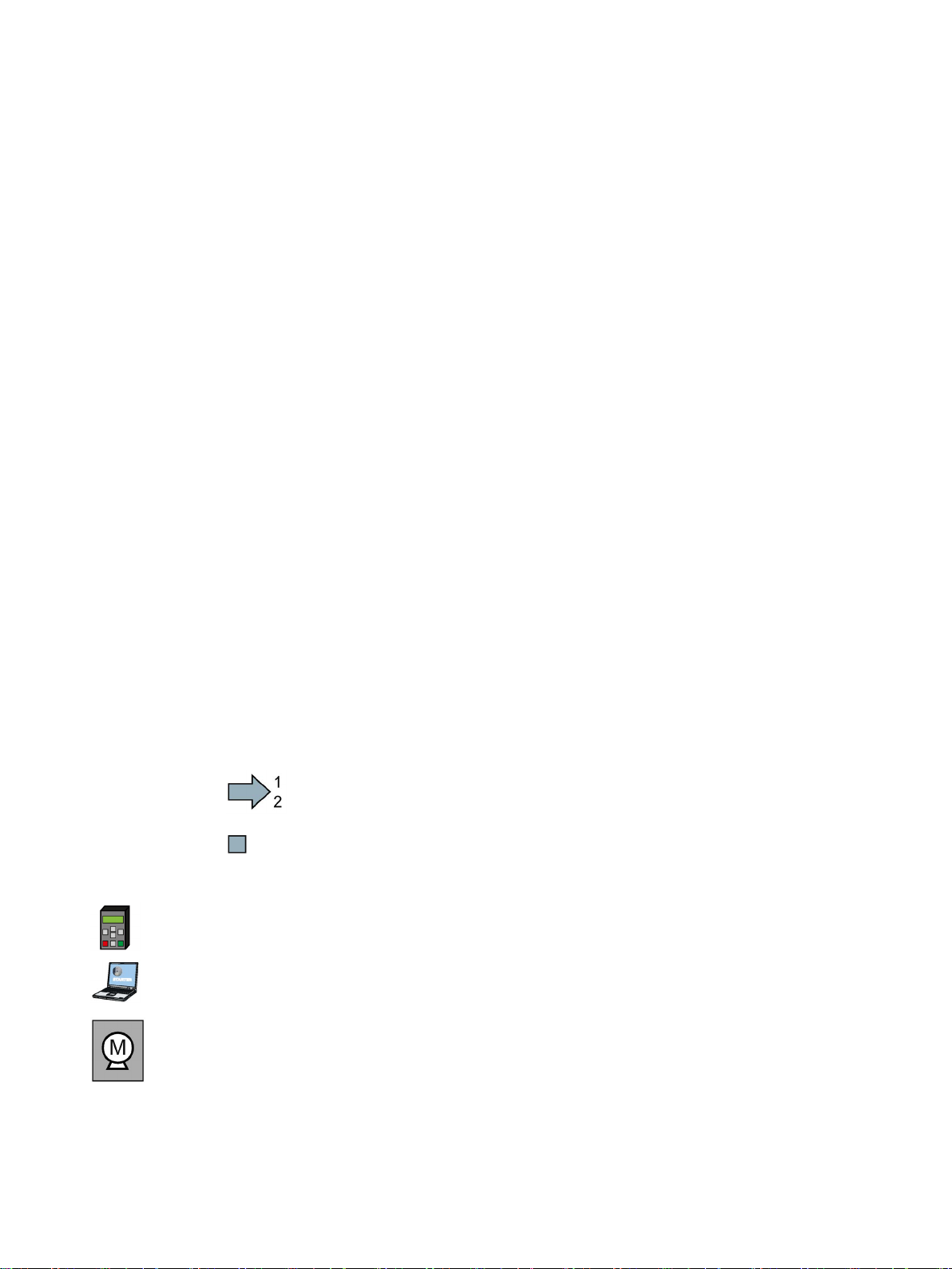
The subsequent text is applicable for an operator panel.
The following text applies if you are using a PC with STARTER.
Symbol for inverter functions.
See also: Overview of the inverter functions (Page 99).
ating instruction.
SIMATIC ET 200pro FC-2 converter
Operating Instructions, 04/2015, FW V4.7.3, A5E34257324B AB
19
Introduction
2.2
Guide through this manual
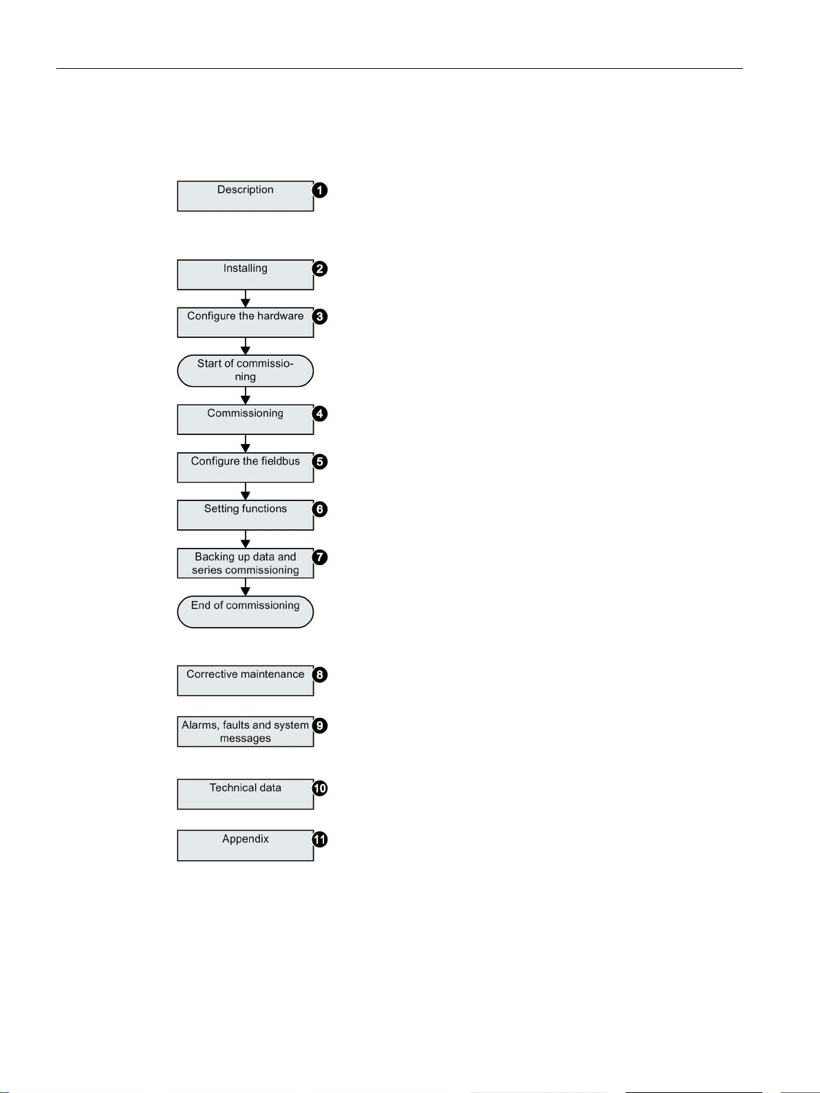
①
Inverter components and accessories.
Permissible motors.
Tools for commissioning.
②
Install and wire the inverter and its components.
③
Configure the ET 200pro station with the inverter.
④
Prepare for commissioning.
Restore the inverter to factory settings.
Define the inverter’s basic settings.
⑤
Configure communication via PROFIBUS or PROFINET.
⑥
Set up the functions, e.g. setpoint processing, motor control
and protection functions.
⑦
Backup the inverter
medium, e.g. a memory card or an operator panel.
⑧
Replace the inverter
Firmware update.
⑨
Meaning of the LEDs on the front of the inverter.
System runtime.
Faults and warnings.
⑩
The most important technical data of the inverter.
⑪
Setting up the new inverter functions.
Application examples.
2.2 Guide through this manual
’s settings to an external data storage
and its components.
SIMATIC ET 200pro FC-2 converter
20 Operating Instructions, 04/2015, FW V4.7.3, A5E34257324B AB

3
Use for the intended purpose
Description
3.1
Components for assembling a frequency converter
General information
The inverter described in this manual is a device for controlling an induction motor. The
inverter is designed for installation in electrical installations or machines.
It has been approved for industrial and commercial use on industrial networks. Additional
measures have to be taken when connected to public grids.
The technical specifications and information about connection conditions are indicated on
the rating plate and in the operating instructions.
The SIMATIC ET 200pro FC-2 is a converter that is completely embedded in the distributed
I/O system SIMATIC ET 200pro.
The following section shows two configuration examples for frequency converters in the
ET 200pro distributed I/O system.
You can find additional general information on the ET 200pro distributed I/O system in the
Internet underET 200pro distributed I/O system
(https://support.industry.siemens.com/cs/de/en/ps/man)
To select components for a ET 200pro distributed I/O system, we recommend the "SIMATIC
ET 200 Configurator".
The ET 200pro system contains a large number of components which the user can combine
according to his needs.
The minimum configuration of a frequency converter requires the following components:
● a rack,
● a complete interface module including a bus terminating module (in the scope of supply of
● the bus module of the frequency converter and the frequency converter itself.
The components described below are examples and represent the minimum configuration of
a standard frequency converter with the safety function STO.
the IM),
SIMATIC ET 200pro FC-2 converter
Operating Instructions, 04/2015, FW V4.7.3, A5E34257324B AB
21
Description
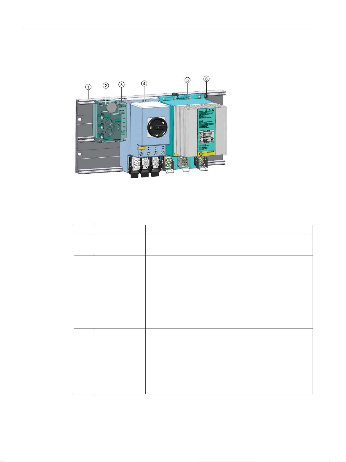
ET 200pro FC-2 with F-RSM
No.
Components
Function
to each other efficiently and accurately.
3.1 Components for assembling a frequency converter
Figure 3-1 ET 200pro FC-2 with F-RSM
Setup the Safe Torque Off (STO) function using local activiation.
Table 3- 1 Components of the ET 200pro FC-2 with F-RSM
1 Mounting rail The mounting rail is used to secure all the components of the
ET200pro system easily and allows the components to be connected
2 Connection modules
for interface modules
3 PROFIBUS DP
interface module
with bus module
The connection modules are mounted on the interface modules. The
modules are designed to allow a variety of connections types suitable
for a number of applications.
The follow connection modules are available:
• Direct connection:
– CM IM DP Direct
• ECOFAST:
– CM IM DP ECOFAST CU
– CM IM DP M12, 7/8"
The interface module interconnects the ET 200pro with the DP master
and prepares the data for the electronic modules.The unit is delivered
with the terminating module. The interface module is already mounted
on the bus module.The bus module is the mechanical and electrical
connection element between the various ET 200pro modules.The
terminating module terminates the ET 200pro.The following interface
modules are available for PROFIBUS DP:
• IM154-1 DP
• IM154-2 DP HF
SIMATIC ET 200pro FC-2 converter
22 Operating Instructions, 04/2015, FW V4.7.3, A5E34257324B AB
Description
No.
Components
Function
RSM must always be plugged
trolled only through local safe inputs (Safety Local function).
using prefabricated cables.
6
Terminating module
The ET 200pro bus is terminated with the terminating module
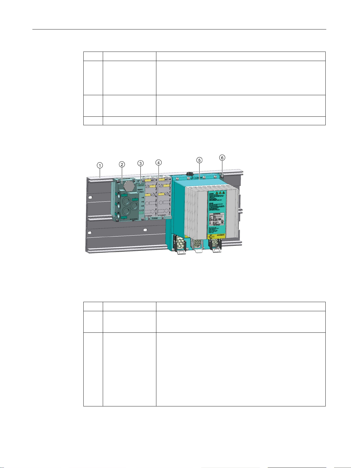
ET 200pro FC-2 with F-Switch
No.
Components
Function
3.1 Components for assembling a frequency converter
4 Safety Local repair
switch module
(F-RSM) with bus
module
5 Converter with bus
module
The F-RSM is used to trigger the safety functions of the converter
through the backplane bus; it switches off the power bus for the motor
starters and frequency converters. An Fin the system to the left of the frequency converter and can be con-
The converter is connected to the higher-level controller by way of the
bus module and interface module; power and motor are connected
Figure 3-2 ET 200pro FC-2 with F-Switch
Setup the Safe Torque Off (STO) function using PROFIsafe.
Table 3- 2 Components of the ET 200pro FC-2 with F-Switch
1 Mounting rail The mounting rail is used to secure all the components of the ET
200pro system easily and allows the components to be connected to
each other efficiently and accurately.
2 Connection modules
for interface modules
The connection modules are mounted on the interface modules. The
modules are designed to allow a variety of connections types suitable
for a number of applications.
The follow connection modules are available:
• Direct connection:
– CM IM DP Direct
• ECOFAST:
– CM IM DP ECOFAST CU
– CM IM DP M12, 7/8"
SIMATIC ET 200pro FC-2 converter
Operating Instructions, 04/2015, FW V4.7.3, A5E34257324B AB
23

Description
No.
Components
Function
the ET 200pro backplane bus.
using prefabricated cables
6
Terminating module
The ET 200pro bus is terminated with the terminating module
3.2
Spare parts and accessories
Optical cable
Optical cable
Order No.
3RK19 22-2BP00
Overview of supplementary products
3.2 Spare parts and accessories
3 PROFINET interface
module with bus
module
4 F-Switch with bus
module
5 Converter with bus
module
The interface module interconnects the ET 200pro with the
PROFINET master and prepares the data for the electronic modules.The unit is delivered with the terminating module. The interface
module is already mounted on the bus module.The bus module is the
mechanical and electrical connection element between the various
ET 200pro modules.The terminating module terminates the
ET 200pro.The following interface modules are available for
PROFINET IO:
• IM154-4 PN
• IM154-6 PN
The F-Switch is used in conjunction with the converter only for the
purpose of switching control signals from the higher-level controller
through PROFIsafe onto the internal switch-off signals F0 and F1 on
The converter is connected to the higher-level controller by way of the
bus module and interface module. Power and motor are connected
The optical cable is used to connect the IOP Handheld Kit with an RS232 interface to the
optical interface of the converter. Electronics integrated in the cable converts electrical
signals of up to 115 kBd into optical signals and vice versa.
A complete, up-to-date listing of all supplementary products for the ET200pro can be found
at the following link:
Listing of supplementary products
(https://support.industry.siemens.com/cs/gb/en/view/65355810)
SIMATIC ET 200pro FC-2 converter
24 Operating Instructions, 04/2015, FW V4.7.3, A5E34257324B AB

Description
Motor cable
Motor cables (discontinued but available as spare parts)
Order No.
Length
6ES7194-1LA01-0AA0
1.5 m
6ES7194-1LB01-0AA0
3.0 m
6ES7194-1LD01-0AA0
10.0 m
Power jumper connector
Power jumper connector
Order No.
3RK19 22-2BQ00
Sealing cap for power bus
Sealing caps for power bus
Order No.
Quantity
3RK19 02-0CK00
1
3RK19 02-0CJ00
10
Memory cards
Scope of delivery
Article number
Memory card without firmware
6SL3054-4AG00-2AA0
Memory card with firmware V4.6
6SL3054-7EG00-2BA0
Memory card with firmware V4.7
6SL3054-7EH00-2BA0
Memory card with firmware V4.7 SP3
6SL3054-7TB00-2BA0
3.2 Spare parts and accessories
Prefabricated motor cables up to 10 m long are available ex stock for connecting the motor.
Longer lengths up to 15 m can be obtained from our SINAMICS service providers.
6ES7194-1LC01-0AA0 5.0 m
Using the power jumper connector it is possible for one converter to loop through up to 25 A
from 3AC 400 V to another frequency converter mounted directly alongside. The common
fusing of the primary supply is provided externally.
Unused connections without a sealing cap have a degree of protection of only IP20, with a
sealing cap it is IP65.
Table 3- 3 Memory cards to back up inverter settings
SIMATIC ET 200pro FC-2 converter
Operating Instructions, 04/2015, FW V4.7.3, A5E34257324B AB
25
Description
3.3
Motor series that are supported
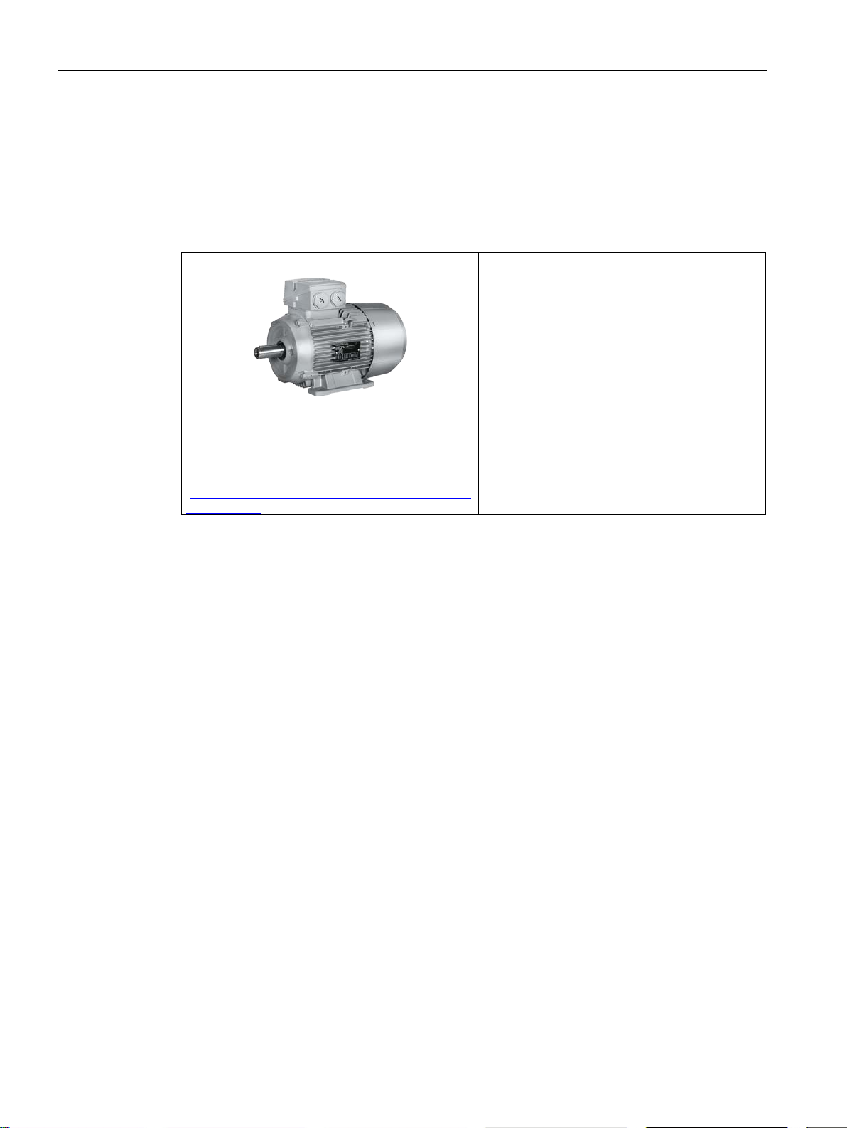
Supported motors
SIMOTICS GP, SIMOTICS SD IEC motors
en/84049346).
Motors from other manufacturers
3.3 Motor series that are supported
Table 3- 4 Motor series suitable for the inverter
1LG6, 1LA7, 1LA9 and 1LE1 standard induction
motors
Multi-motor drive is permissible, i.e. multiple motors operated on one inverter. See also: Multimotor drive
(http://support.automation.siemens.com/WW/view/
Standard induction motors
SIMATIC ET 200pro FC-2 converter
26 Operating Instructions, 04/2015, FW V4.7.3, A5E34257324B AB
Description
3.4
Tools to commission the inverter
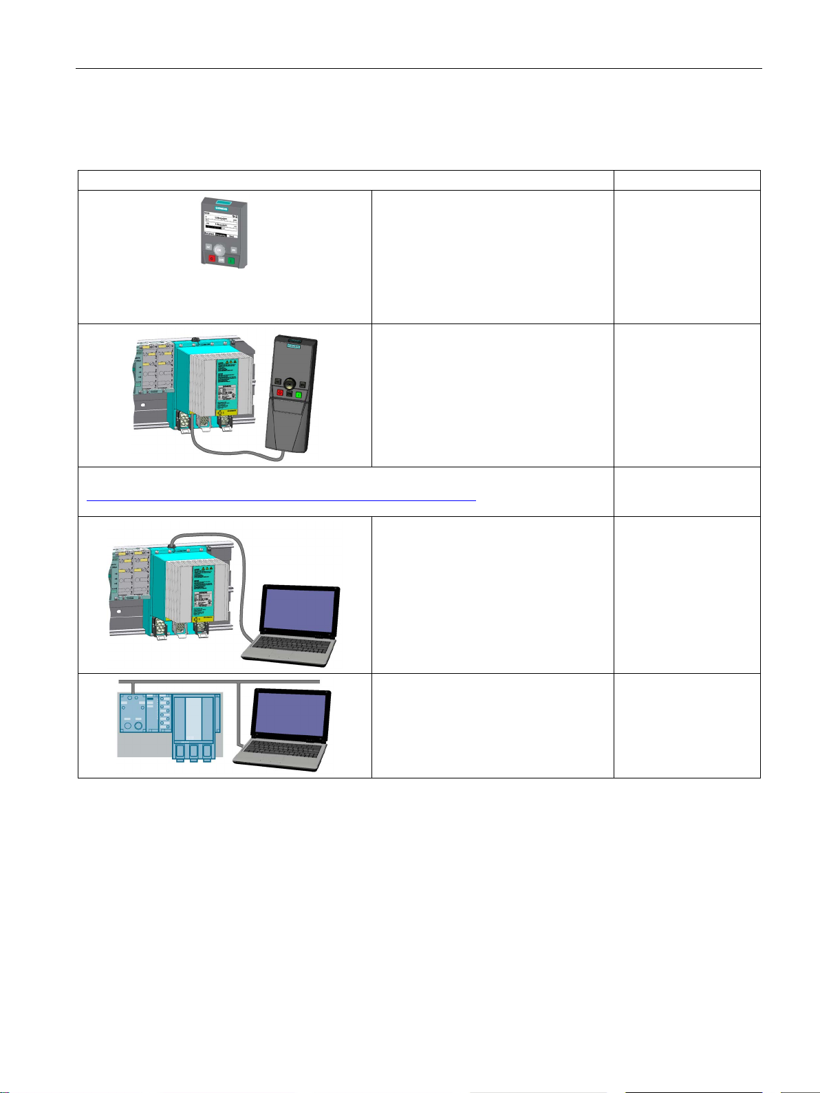
Operator panel for commissioning, diagnostics and controlling converters
Article No.
PC tool
troubleshooting and controlling the frequency converter
3.4 Tools to commission the inverter
IOP (Intelligent Operator Panel) - for
snapping on the IOP handheld
• Plain text display
"STARTER" (download
(http://support.automation.siemens.com/WW/view/en/10804985/130000))
• Menu-based operation and application
wizards
• Backing up and transferring the con-
verter settings
IOP handheld with power supply unit and
rechargeable batteries as well as RS232
connection cable
If you are using your own connection
cable, carefully note the maximum permissible length of 5 m.
connected with the frequency converter
via USB interface. (SINAMICS PCfrequency converter connecting set -2)
6SL3255-0AA00-4JA0
6SL3255-0AA00-4HA0
6SL3072-0AA00-0AG0
for commissioning,
6SL3255-0AA00-2CA0
connected with the frequency converter
via fieldbus and head module (IM 154-x)
SIMATIC ET 200pro FC-2 converter
Operating Instructions, 04/2015, FW V4.7.3, A5E34257324B AB
27

Description
3.4 Tools to commission the inverter
SIMATIC ET 200pro FC-2 converter
28 Operating Instructions, 04/2015, FW V4.7.3, A5E34257324B AB
4
DANGER
Operation with ungrounded (IT) mains supplies can produce extremely dangerous
conditions
DANGER
Risk of burns and fire due to high temperatures
WARNING
Direct current on the PE conductor
only a type B RCD
4.1
Prerequisites and maximum expansion
WARNING
The converter must always be grounded. If the converter is not grounded correctly,
extremely dangerous conditions may arise within the inverter which could prove potentially
fatal.
The converter can only be used on TT and TN mains supplies.
During operation and for a short time after switching the converter off, the surfaces reach
temperatures that can inflict burns or start fires!
Before attempting to touch the surfaces of the converter, ensure that enough time is given
to allow the converter to cool down to a safe temperature to avoid personal injury.
Remove any flammable materials from around the converter to reduce the risk of fire.
This product can cause a direct current on the PE conductor.
If the wrong type of protection device is used, then the expected protection by such a
device could fail to provide the expected protection.
If a residual current device (RCD) is used to provide protection in case of direct or indirect
contact,
Danger to life from spread of fire in the event of contact with hot surfaces
The inverter housing can reach an operating temperature that may cause a fire.
• Store easily inflammable materials at a sufficient distance from the inverter.
may be used on the power supply side of this product.
SIMATIC ET 200pro FC-2 converter
Operating Instructions, 04/2015, FW V4.7.3, A5E34257324B AB
29

Installation
Maximum size
Features
Rule
ules
Width
≤ 1 m (without rack)
ers
ET 200pro features
Inverter features
Rule
Load capacity of the electronics supply 1L+
≤ 5 A
Power consumption at 1L+
≤ 0.8 A per inverter
Load capacity of the load voltage supply 2L+
≤ 10 A
is negligible.
Current carrying capacity of the power supply
≤ 25 A
power supply
on the connected motor.
4.2
Mounting the racks
4.2 Mounting the racks
The width of an ET 200pro is limited mechanically and electrically.
Table 4- 1 Mechanical limits
Number of mod-
Number of invert-
Table 4- 2 Electrical limits
Power consumption at 2L+ The load caused by the frequency inverter
Power consumption at the
≤ 16
≤ 5
The inverter’s power consumption depends
The frequency converter is mounted on the wide rack. The following versions are possible:
● Rack, wide
● Rack, compact-wide
SIMATIC ET 200pro FC-2 converter
30 Operating Instructions, 04/2015, FW V4.7.3, A5E34257324B AB
 Loading...