

Siemens SIMATIC ET 200pro User Manual

ET 200pro distributed I/O EtherNet/IP
interface module
___________________
___________________
___________________
___________________
___________________
___________________
___________________
___________________
___________________
SIMATIC
ET 200pro distributed I/O EtherNet/IP interface module
Manual
03/2016
A5E32861915
Preface
1
Product overview
2
The ET 200pro EtherNet/IP
module
3
Installing, mounting, and
connecting
4
Commissioning
5
General technical
specifications
6
Order number
A
Dimension drawing
B
Address area
C
-AB

Siemens AG
Division Digital Factory
Postfach 48 48
90026 NÜRNBERG
GERMANY
A5E32861915-AB
Ⓟ
Copyright © Siemens AG 2014 - 2016.
All rights reserved
Legal information
Warning notice system
DANGER
indicates that death or severe personal injury will result if proper precautions are not taken.
WARNING
indicates that death or severe personal injury may result if proper precautions are not taken.
CAUTION
indicates that minor personal injury can result if proper precautions are not taken.
NOTICE
indicates that property damage can result if proper precautions are not taken.
Qualified Personnel
personnel qualified
Proper use of Siemens products
WARNING
Siemens products may only be used for the applications described in the catalog and in the relevant technical
maintenance are required to ensure that the products operate safely and without any problems. The permissible
ambient conditions must be complied with. The information in the relevant documentation must be observed.
Trademarks
Disclaimer of Liability
This manual contains notices you have to observe in order to ensure your personal safety, as well as to prevent
damage to property. The notices referring to your personal safety are highlighted in the manual by a safety alert
symbol, notices referring only to property damage have no safety alert symbol. These notices shown below are
graded according to the degree of danger.
If more than one degree of danger is present, the warning notice representing the highest degree of danger will
be used. A notice warning of injury to persons with a safety alert symbol may also include a warning relating to
property damage.
The product/system described in this documentation may be operated only by
task in accordance with the relevant documentation, in particular its warning notices and safety instructions.
Qualified personnel are those who, based on their training and experience, are capable of identifying risks and
avoiding potential hazards when working with these products/systems.
Note the following:
documentation. If products and components from other manufacturers are used, these must be recommended
or approved by Siemens. Proper transport, storage, installation, assembly, commissioning, operation and
All names identified by ® are registered trademarks of Siemens AG. The remaining trademarks in this publication
may be trademarks whose use by third parties for their own purposes could violate the rights of the owner.
We have reviewed the contents of this publication to ensure consistency with the hardware and software
described. Since variance cannot be precluded entirely, we cannot guarantee full consistency. However, the
information in this publication is reviewed regularly and any necessary corrections are included in subsequent
editions.
for the specific
03/2016 Subject to change

Table of contents
1 Preface ................................................................................................................................................... 5
2 Product overview .................................................................................................................................... 8
3 The ET 200pro EtherNet/IP module....................................................................................................... 17
4 Installing, mounting, and connecting ...................................................................................................... 51
2.1 What are distributed I/O systems? ............................................................................................ 8
2.2 What is the ET 200pro distributed I/O system? ........................................................................ 9
2.3 Components of the ET200pro distributed I/O system ............................................................. 12
2.4 The ET 200pro EtherNet/IP interface module ........................................................................ 14
2.5 Features and benefits of the ET 200pro EtherNet/IP module................................................. 16
3.1 ET 200pro EtherNet/IP module hardware............................................................................... 17
3.2 Operation ................................................................................................................................ 19
3.3 Parameters for the ET 200pro EtherNet/IP module ................................................................ 22
3.4 Faults ...................................................................................................................................... 23
3.5 Troubleshooting ...................................................................................................................... 26
3.6 Replacing a faulty ET 200pro EtherNet/IP module ................................................................. 28
3.7 Device profile: supported CIP objects ..................................................................................... 29
3.7.1 Identity Object ......................................................................................................................... 29
3.7.2 Assembly Object ..................................................................................................................... 32
3.7.3 Connection Manager Object ................................................................................................... 34
3.7.4 TCP/IP Interface Object .......................................................................................................... 35
3.7.5 EtherNet Link Object ............................................................................................................... 38
3.8 Device profile: vendor-specific objects ................................................................................... 41
3.8.1 Adapter Object ........................................................................................................................ 41
3.8.2 Slot Object .............................................................................................................................. 45
3.9 Technical specifications .......................................................................................................... 49
4.1 Installing .................................................................................................................................. 51
4.2 Mounting ................................................................................................................................. 51
4.3 Connecting .............................................................................................................................. 52
ET 200pro distributed I/O EtherNet/IP interface module
Manual, 03/2016, A5E32861915-AB
3

Table of contents
5 Commissioning ..................................................................................................................................... 53
6 General technical specifications ............................................................................................................ 66
A Order number ....................................................................................................................................... 76
B Dimension drawing ............................................................................................................................... 77
C Address area ........................................................................................................................................ 78
Index .................................................................................................................................................... 79
5.1 Configuring the ET 200pro EtherNet/IP module .................................................................... 53
5.2 Setting the IP address ............................................................................................................ 53
5.3 Grouping electronic modules ................................................................................................. 54
5.4 Commissioning and startup ................................................................................................... 58
5.5 Using QuickConnect .............................................................................................................. 59
5.5.1 QuickConnect overview ......................................................................................................... 59
5.5.2 Guidelines for using QuickConnect on your network ............................................................. 60
5.5.3 Replacing a faulty QuickConnect Adapter ............................................................................. 63
5.5.4 Troubleshooting and optimization .......................................................................................... 64
5.6 Firmware updates .................................................................................................................. 65
6.1 Standards and approvals ....................................................................................................... 66
6.2 Electromagnetic compatibility ................................................................................................ 69
6.3 Shipping and storage conditions ............................................................................................ 70
6.4 Mechanical and climatic environmental conditions ................................................................ 71
6.5 Specifications for insulation tests, protection class, degree of protection, and rated
voltage .................................................................................................................................... 74
ET 200pro distributed I/O EtherNet/IP interface module
4 Manual, 03/2016, A5E32861915-AB

1
Trademarks
Purpose of the manual
Required level of knowledge
Scope of the manual
Certifications, Marks, and Standards
This manual references technologies whose names are trademarked by ODVA, the Open
DeviceNet Vendors Association. The ODVA technologies referenced in this manual include:
EtherNet/IP™
CIP™ (Common Industrial Protocol)
QuickConnect™
For more information on ODVA and its trademarked technologies, visit the ODVA website
(http://www.odva.org).
The information in this manual is intended to enable you to operate the ET 200pro
EtherNet/IP interface module on EtherNet/IP.
You require knowledge of the automation engineering field in order to use the material in this
manual.
This manual is valid for the ET 200pro EtherNet/IP module. Appendix A provides order
information.
This manual contains a description of the components that were valid at the time the manual
was published. Information about new components and new versions of components is
released in Product Information bulletins available on the Siemens Industry Online Support
(https://support.industry.siemens.com/cs/?lc=en-US) website.
The ET 200pro EtherNet/IP module complies with EtherNet/IP Specification CIP Networks
Library Volume 2: EtherNet/IP Adaption of CIP, Edition 1.16.
See the "General technical specifications" chapter for a full description of all applicable
certifications, marks, and standards.
ET 200pro distributed I/O EtherNet/IP interface module
Manual, 03/2016, A5E32861915-AB
5

Preface
Relevant manuals
Software
Recycling and disposal
Online product support
The following manuals are included on the disk that shipped with your ET 200pro
EtherNet/IP module:
● ET 200pro EtherNet/IP interface module System Manual (this manual)
● ET 200pro distributed I/O System Operating Instructions
● EIP ET200 Configuration Tool User Reference Guide
The following manual is also relevant to the ET 200pro system. They can be found on the
Siemens Industry Online Support (https://support.industry.siemens.com/cs/?lc=en-US)
website:
● ET 200pro Motor starters Manual
In order to configure the ET 200pro EtherNet/IP module, you require the EIP ET200
Configuration Tool software. This software is located on the companion disk that shipped
with your ET 200pro EtherNet/IP module.
Because it is low in contaminants, the ET 200pro EtherNet/IP module is recyclable. Contact
a certified electronic waste disposal company to recycle and dispose of your old equipment
in an environmentally-friendly manner.
If you have questions about using the ET 200pro EtherNet/IP module that the documentation
does not address, go to the Siemens Industry Online Support
(https://support.industry.siemens.com/cs/?lc=en-US) website and search on "ET 200pro".
ET 200pro distributed I/O EtherNet/IP interface module
6 Manual, 03/2016, A5E32861915-AB

Preface
Security information
Siemens provides products and solutions with industrial security functions that support the
secure operation of plants, solutions, machines, equipment and/or networks. They are
important components in a holistic industrial security concept. With this in mind, Siemens’
products and solutions undergo continuous development. Siemens recommends strongly
that you regularly check for product updates.
For the secure operation of Siemens products and solutions, it is necessary to take suitable
preventive action (e.g. cell protection concept) and integrate each component into a holistic,
state-of-the-art industrial security concept. Third-party products that may be in use should
also be considered. You can find more information about industrial security on the Internet
(http://www.siemens.com/industrialsecurity).
To stay informed about product updates as they occur, sign up for a product-specific
newsletter. You can find more information on the Internet
(http://support.automation.siemens.com).
ET 200pro distributed I/O EtherNet/IP interface module
Manual, 03/2016, A5E32861915-AB
7

2
2.1
What are distributed I/O systems?
When a system is set up, the inputs and outputs from and to the process are often located
centrally in the programmable logic controller.
If there are inputs and outputs at considerable distances from the PLC, there may be long
runs of cabling that are not immediately comprehensible. Additionally, electromagnetic
interference may impair reliability.
Using a distributed I/O system provides the following benefits:
● The controller CPU is located centrally.
● The I/O systems (inputs and outputs) operate locally on a distributed basis.
● The high-performance ET 200pro system ensures that the PLC and I/O systems
communicate smoothly.
ET 200pro distributed I/O EtherNet/IP interface module
Manual, 03/2016, A5E32861915-AB
8

Product overview
2.2
What is the ET 200pro distributed I/O system?
Fields of application
Area of application
Configuration
Terminal modules and electronic modules
2.2 What is the ET 200pro distributed I/O system?
The ET 200pro distributed I/O system is a modular distributed I/O system available in
degrees of protection IP65, IP66, and IP67.
A robust design and degree of protection IP65, IP66, or IP67 make the ET 200pro
EtherNet/IP module particularly suitable for use in rugged industrial environments.
With IP65, IP66 and IP67, the ET 200pro EtherNet/IP module is protected against the
ingress of foreign bodies and water. The module does not require an additional enclosure.
The ET 200pro EtherNet/IP module supports communication with:
● Fieldbus
● Fieldbus Data Link Layer
For more information, see the topic "Standards and approvals".
With the ET 200pro system, you can connect virtually any number of I/O modules in virtually
any combination right next to the interface module. This means that you can adjust the
configuration to suit local requirements.
The ET 200pro EtherNet/IP module is installed on a rack and basically consists of the
following:
● An interface module that transfers data to the EtherNet/IP master
● Up to 16 electronic modules with maximum 1 m total width (without rack)
● Connection modules in various designs for
● Pneumatic interface modules for linking of FESTO valve terminals
You can thus set the focus of your configuration on local requirements.
The convenient handling features of ET 200pro EtherNet/IP module ensure quick
commissioning and easy maintenance.
– ET 200pro EtherNet/IP module
– Supply voltages
– Inputs and outputs
The ET 200pro distributed I/O system consists primarily of various passive connection
modules to which you connect the electronic modules and motor starters.
The ET 200pro EtherNet/IP module enables the ET 200pro distributed I/O system to be
connected to the EtherNet/IP network.
ET 200pro distributed I/O EtherNet/IP interface module
Manual, 03/2016, A5E32861915-AB
9
Product overview
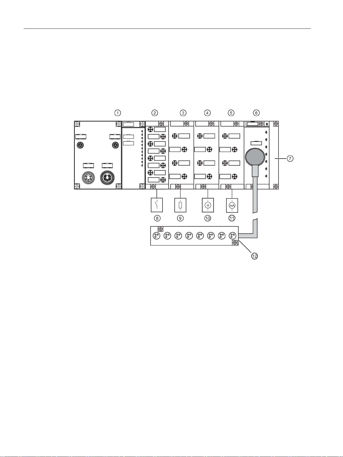
Example configuration with electronic modules
①
ET
②
8 DI DC 24V
③
4 DO DC 24V/2.0A
4 AI U HF
⑤
4 AI I HF
⑥
8 DI DC 24V
⑦
Terminating module
⑧
8 x switches, sensors
⑨
4/8 x load
⑩
4 x voltage measurement
⑪
4 x current measurement for 2
⑫
Actuator/sensor distributor
2.2 What is the ET 200pro distributed I/O system?
The ET 200pro EtherNet/IP module can be equipped up to the maximum configuration with
electronic modules. Between an interface module and a terminating module you can adapt
the electronic modules to your application in whatever configuration you require.
The figure below shows an example configuration of the ET 200pro distributed I/O system.
④
200pro EtherNet/IP interface module (with connection module)
-/4-wire measuring transducer
ET 200pro distributed I/O EtherNet/IP interface module
10 Manual, 03/2016, A5E32861915-AB
Product overview
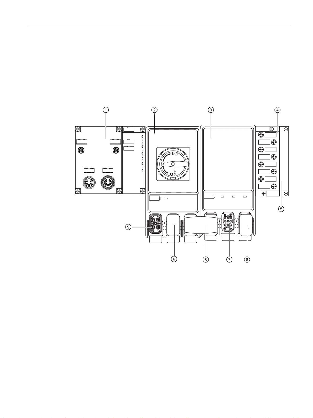
Example configuration with electronic module and motor starter
①
ET
②
Repair switch module
③
DSe; Standard
④
8 DI DC 24
⑤
Terminating module
⑥
Cap
⑦
Motor connection
⑧
Power jumper plug
⑨
Infeed
2.2 What is the ET 200pro distributed I/O system?
Between an interface module and a terminating module you can adapt the electronic
modules, motor starters and frequency converters to your applications in whatever
configuration you require.
The figure below shows an example configuration of the ET 200pro distributed I/O system
with motor starter and repair switch module.
ET 200pro distributed I/O EtherNet/IP interface module
Manual, 03/2016, A5E32861915-AB
200pro EtherNet/IP interface module (with connection module)
V
11
Product overview
2.3
Components of the ET200pro distributed I/O system
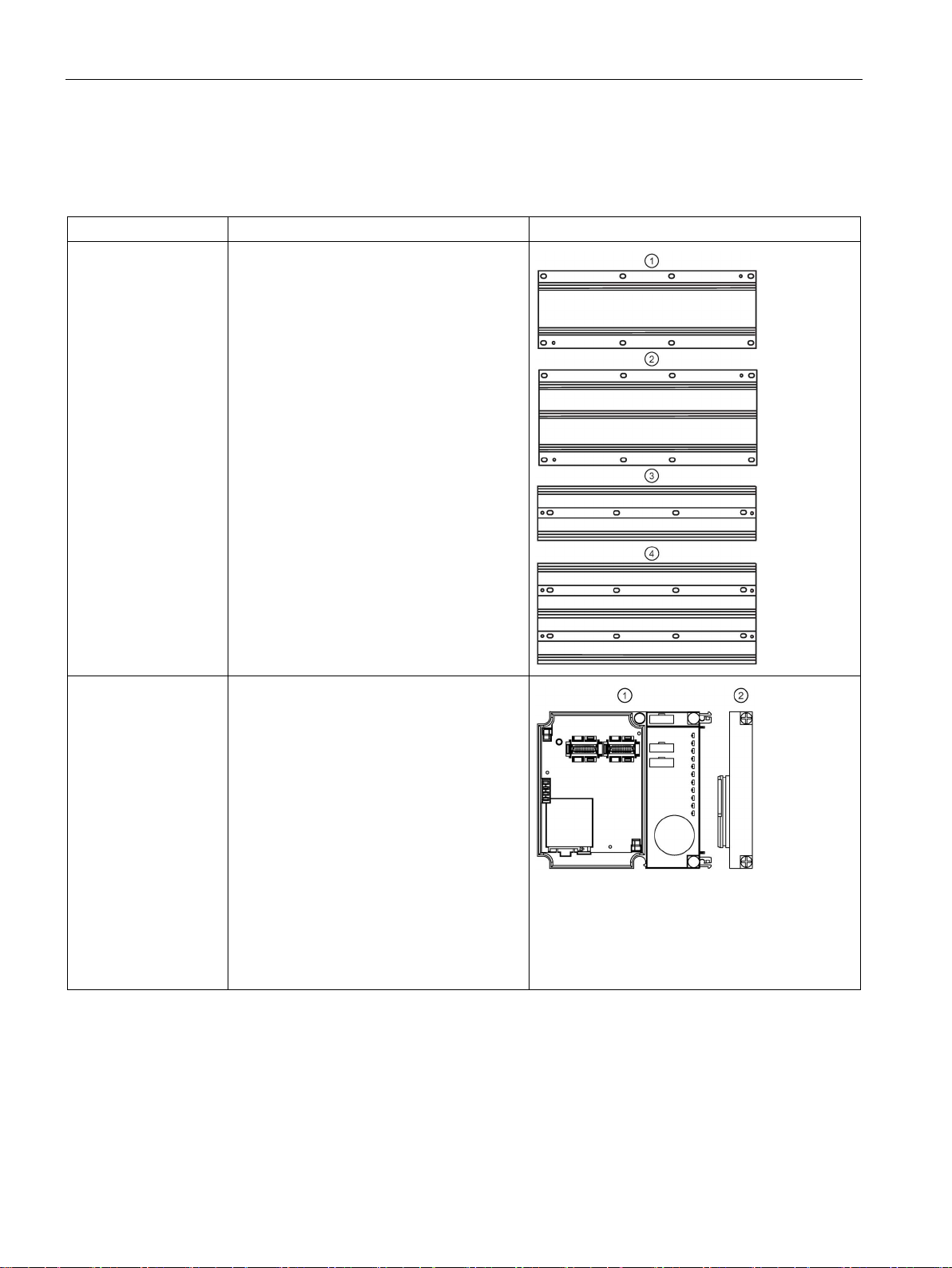
Component
Function
View
2.3 Components of the ET200pro distributed I/O system
The table below lists the most important components of an ET 200pro system.
Rack The ET 200pro is mounted onto the rack.
Four versions with different lengths are available:
Rack, narrow
Rack, wide ②
Rack, compact narrow ③
Rack, compact wide ④
①
Interface module for
EtherNet/IP with bus
module and terminating module
The interface module interconnects
ET 200pro with the EtherNet/IP master and
prepares the data for the electronic modules.
The unit is delivered with the terminating
module
already mounted on the bus module.
• The bus module is the mechanical and
• The terminating module terminates the
The following interface modules are available
for EtherNet/IP:
• ET 200pro EtherNet/IP interface module
②, and the interface module ① is
electrical connection element between
the various ET 200pro modules.
ET 200pro, backplane bus.
(ZNX:EIP200PRO)
ET 200pro distributed I/O EtherNet/IP interface module
12 Manual, 03/2016, A5E32861915-AB
Product overview
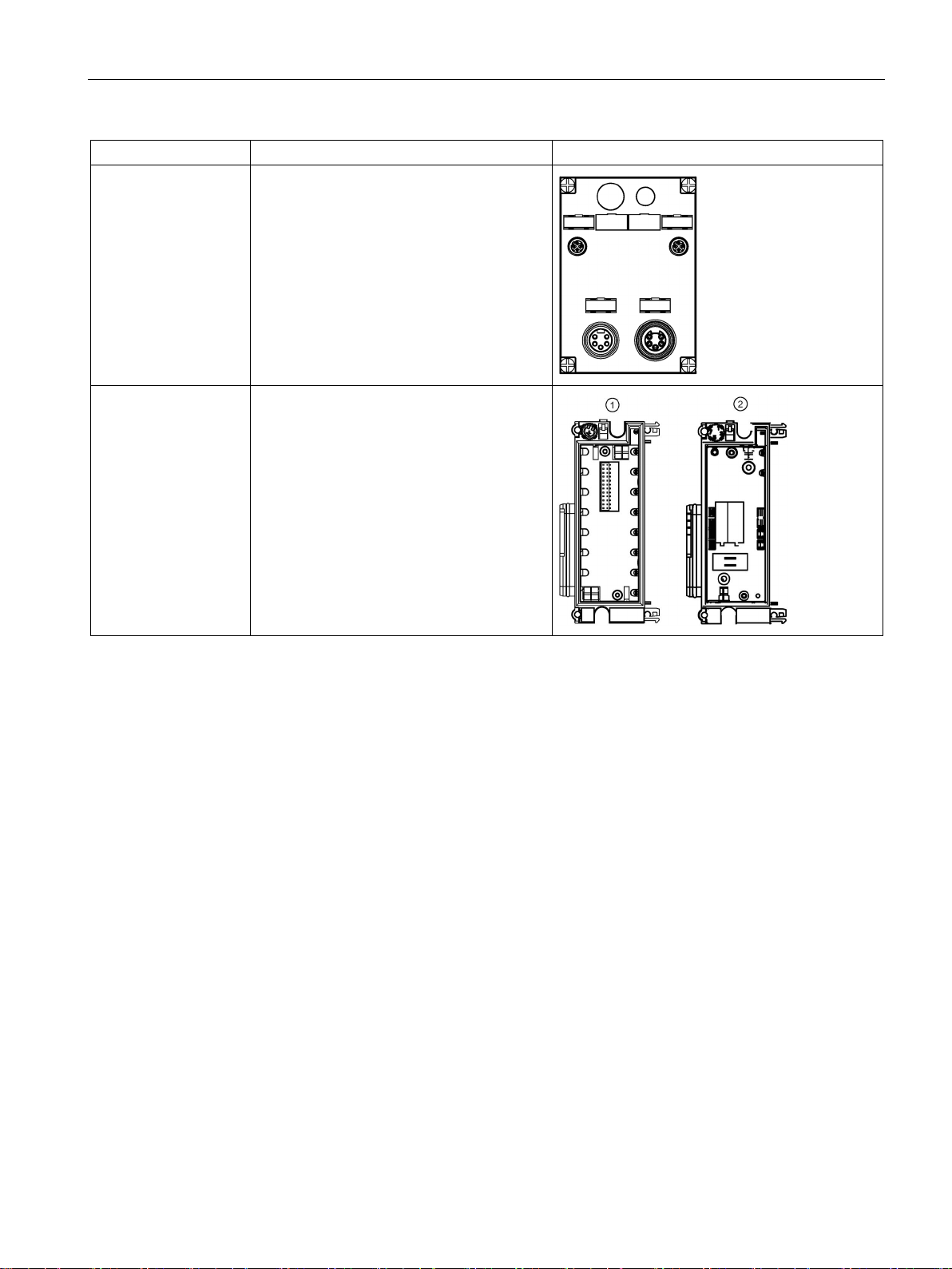
Component
Function
View
Power module with bus
2.3 Components of the ET200pro distributed I/O system
Connection module for
the ET 200pro EtherNet/IP interface module
module and outgoing
module
The connection module is mounted on the
interface module. It is used to connect
EtherNet/IP and the electronic, encoder, and
load voltage supplies.
The following connection module is available
for EtherNet/IP:
• CM IM M12, 7/8" (ZNX:ET200PROCM1)
① The power module provides a new poten-
tial group for the 2L+ load voltage supply.
The unit is shipped with the power module
mounted on the bus module.
② The outgoing module enables the 1L+
electronics/encoder supply and the 2L+ load
voltage supply to be tapped.
ET 200pro distributed I/O EtherNet/IP interface module
Manual, 03/2016, A5E32861915-AB
13

Product overview
2.4
The ET 200pro EtherNet/IP interface module
ET 200pro EtherNet/IP interface module package
Order number
ET 200pro EtherNet/IP interface module features
Note
Operating with ungrounded reference potential
When the ET
and 1M and FE are not interconnected, any interference currents are discharged
protective ground via an internal RC circuit.
2.4 The ET 200pro EtherNet/IP interface module
The ET 200pro EtherNet/IP interface module package includes the following components:
● Interface module and terminating module (ET 200pro EtherNet/IP)
● Companion disk with EIP ET200 Configuration Tool software, EIP ET200 Configuration
Tool User Reference Guide, and this ET 200pro EtherNet/IP interface module manual
The order number for this package is: ZNX:EIP200PRO.
The ET 200pro EtherNet/IP module is a communications adapter for interfacing with an
ET 200pro distributed I/O system. It provides connectivity between an EtherNet/IP network
and ET 200pro power and I/O modules, and has the following features:
● It prepares the data for electronic modules and motor starters.
● It supplies the backplane bus.
● The maximum address space is 255 bytes for inputs and 255 bytes for outputs.
● The connection between 1M and FE is not applicable in a configuration with ungrounded
reference potential.
● A maximum of 16 modules can be operated with the interface module.
● The maximum width of the station is 1 m.
● The maximum parameter length for the entire station is 237 bytes.
● You can group modules within one byte (packing).
200pro EtherNet/IP module is operated with ungrounded reference potential
to
ET 200pro distributed I/O EtherNet/IP interface module
14 Manual, 03/2016, A5E32861915-AB
Product overview
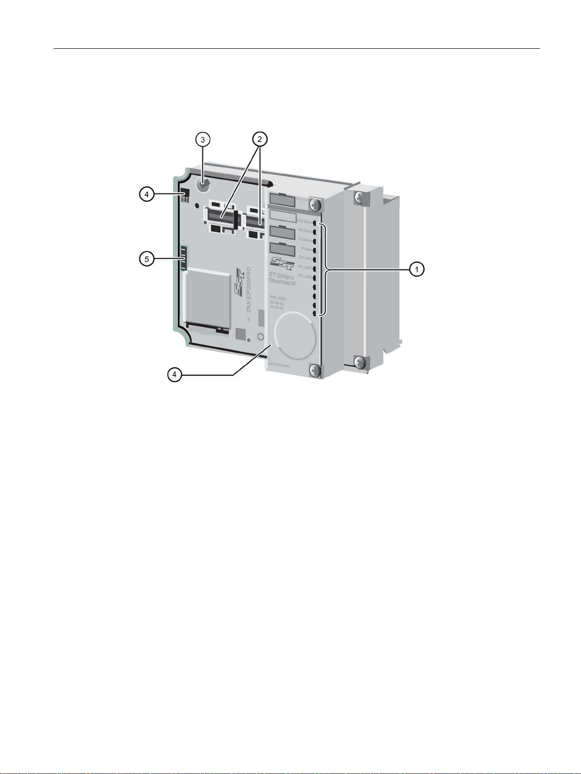
①
Status LEDs
②
Connection module interface
③
Coding element
④
Ground connections
⑤
Power connection
I/O features
2.4 The ET 200pro EtherNet/IP interface module
The following illustration shows the hardware features of the ET 200pro EtherNet/IP module:
The ET 200pro EtherNet/IP module provides the following I/O features:
● Provides support for a subset of ET 200pro modules
● Supports up to 16 modules per ET 200pro EtherNet/IP module
● Supports electronic module parameterization
● Supports electronic module diagnostics
ET 200pro distributed I/O EtherNet/IP interface module
Manual, 03/2016, A5E32861915-AB
15

Product overview
2.5
Features and benefits of the ET 200pro EtherNet/IP module
Features
Benefits
Structure
Extensive range of electronic modules
Broad area of application
tions (10 g vibration resistance)
the machine, high availability
Connection system
Integrated voltage buses
Reduced effort required for wiring
Power bus up to 25 A for motor starters
Minimization of wiring in 400 V range
essary
IP65, IP66, and IP67 connection modules
A change in connection method is not necessary
Automatic coding of the I/O modules
Quick and reliable module replacement
Large label plate
Adequate space for clear identification
accordance with EN 954-1
2.5 Features and benefits of the ET 200pro EtherNet/IP module
The following table lists the features and benefits of the ET 200pro EtherNet/IP module:
Finely-graduated modular design:
• 4/8/16 channel electronic modules
• Power modules
• Integrated motor starters
Communication capacity, system-integrated
motor starter: direct and reversing starter to
7.5 kW
Permanent wiring due to the separation of the
connection module and electronic components
Individual connection of power modules to
common potential
Robust structure for rough industrial condi-
M8, M12, and M23 connections A change in terminal connection method is not nec-
• Function-oriented, cost-optimized station design
• Considerable reduction in outlay for configuration
and documentation
• Space savings due to arbitrary arrangement of
the modules
PLC inputs and outputs, terminal blocks, circuit
breakers and contactors in a plug-in module save
space and the effort involved in wiring
• Prewiring possible
• Module replacement during operation of the
ET 200pro EtherNet/IP module ("hot swapping")
• Individual formation of potential groups
• Simple load interruption
High operating reliability when mounted directly on
• 2- and 3-wire connection, or
• 2-, 3- and 4-wire connection
With motor starters up to safety category 4 in
Optimal selection on grounds of space and cost
Saves money on costly safety equipment
ET 200pro distributed I/O EtherNet/IP interface module
16 Manual, 03/2016, A5E32861915-AB

3
3.1
ET 200pro EtherNet/IP module hardware
Hardware configuration
LED status indicators
LED status indicator: Module Status LED
State
Description
Invalid parameter data.
commissioning due to configuration
Red
Unrecoverable fault detected: hardware failure.
You can operate your ET 200pro EtherNet/IP module in automatic configuration mode, or
you can use the EIP ET200 Configuration Tool software to operate in user configured mode.
The software and associated User Reference Guide can be found on the companion disk
that shipped with your module, or downloaded from the Siemens Industry Online Support
(https://support.automation.siemens.com/cs/?lc=en-US) website.
The ET 200pro EtherNet/IP module has three bi-color LEDs that provide diagnostic
information about the current state of the device and provide an indication of any faults. The
LEDs conform to the behaviors defined in the ODVA EtherNet/IP Adaptation of CIP Adapter
Specification for the Module Status and Network Status LEDs, and in this manual for I/O
Status LEDs.
The bi-color Module Status LED indicates the current state of the ET 200pro EtherNet/IP
module, as described in the following table:
Off No power applied to device.
Flashing green Device has not been configured.
Green Device has initialized successfully and no errors
Flashing red Recoverable fault.
were detected.
Device needs
error:
• Invalid parameter data
• Invalid slot configuration data.
ET 200pro distributed I/O EtherNet/IP interface module
Manual, 03/2016, A5E32861915-AB
17

The ET 200pro EtherNet/IP module
LED status indicator: Network Status LED
State
Description
Green
Connected.
Red
Duplicate IP address detected.
LED status indicator: I/O Status LED
State
Description
mal operation, RUN mode).
I/O is active.
3.1 ET 200pro EtherNet/IP module hardware
The bi-color Network Status LED indicates the current state of the ET 200pro EtherNet/IP
communications link, as described in the following table:
Off
Flashing green No connection - an IP address is configured, but
Flashing red One or more CIP connections have timed out.
The bi-color I/O Status LED provides diagnostic information about the current state of the I/O
under the control of the ET 200pro EtherNet/IP module, as described in the following table:
Off
Green Device online with connections established (nor-
• Device is powered off, or is powered on but
does not have an IP address.
• May be waiting for IP address if in
DHCP/BOOTP mode.
no CIP connections are established.
• All outputs and inputs are inactive.
• Configuration errors prevent enabling of in-
puts/outputs.
• No connection.
• Device not powered.
Flashing green
Flashing red One or more outputs or inputs are faulted when
ET 200pro distributed I/O EtherNet/IP interface module
• Device online with connections established
(normal operation, IDLE mode).
• Firmware update in progress.
18 Manual, 03/2016, A5E32861915-AB

The ET 200pro EtherNet/IP module
3.2
Operation
Automatic Configuration mode
Note
Motor starters require User
3.2 Operation
The ET 200pro EtherNet/IP interface module is capable of operating out of the box in
Automatic Configuration mode without any special configuration software. Automatic
Configuration mode is the default mode.
However, to take full advantage of advanced diagnostics and features, you can operate in
User-configured mode by using the EIP ET200 Configuration Tool software.
You can access the Configuration Tool software and associated User Reference Guide in
one of two places:
● on the companion disk that shipped with your ET 200pro EtherNet/IP interface module
● on the Siemens Industry Online Support website
(https://support.automation.siemens.com/cs/?lc=en-US)
When operating in Automatic Configuration mode, the ET 200pro EtherNet/IP module
configures its I/O sizes, I/O module parameterization data, and configuration data according
to the combination of ET 200pro modules present at power-up or reset. In Automatic
Configuration mode:
● Electronic module parameter data cannot be specified. The modules use the default
parameters. You must make certain that the default parameters for the modules satisfy
your application requirements.
● I/O configuration cannot be verified. The ET 200pro EtherNet/IP module verifies the
configuration by examining I/O sizes.
Note that the ET 200pro EtherNet/IP module is unable to differentiate modules of similar
configuration types (for example, a 2 A discrete output module as compared to a 0.5 A
discrete output module):
● The I/O data format is defined by the combination of modules installed.
● I/O module grouping is enabled.
● The I/O status byte is enabled.
-configured mode.
ET 200pro distributed I/O EtherNet/IP interface module
Manual, 03/2016, A5E32861915-AB
19

The ET 200pro EtherNet/IP module
User-configured mode
Changes to configuration data
Setting the IP address
I/O status byte
3.2 Operation
When operating in User-configured mode, the ET 200pro EtherNet/IP module I/O sizes, I/O
module parameterization data, and I/O configuration data are stored in nonvolatile memory
and accessed via the Slot Object. In User-configured mode:
● You can modify electronic module parameter data, allowing access to more advanced
configuration options and diagnostics.
● I/O configuration is verified. Mismatching I/O configurations result in an error.
Note that the ET 200pro EtherNet/IP module is unable to differentiate modules of similar
configuration types (for example, a 2 A discrete output module as compared to a 0.5 A
discrete output module).
● You can set Slot Object instance attributes (as long as there are no open I/O
connections).
● You define the I/O data format by the combination of modules you configure.
● I/O module grouping is available, but you must define it by your configuration selections.
Changes to user configuration data take effect immediately after download without resetting
the device.
Changes to user configuration data are stored in nonvolatile memory immediately (before the
explicit message response is sent).
DHCP is the factory default. When the ET 200pro EtherNet/IP module is using DHCP, you
can set IP addresses by using Microsoft Windows and Linux DHCP/BOOTP servers. There
are several free servers for Microsoft Windows available for download from the Internet. Use
discretion when downloading software from the Internet.
After you set the IP address with DHCP, you can use the EIP ET200 Configuration Tool to
set a permanent IP address and turn off DHCP. See the "EIP ET200 Configuration Tool User
Reference Guide" for detailed instructions.
The Adapter Object IO_StatusEnable attribute allows you to enable or disable the generation
of an additional I/O status byte to detect faults in the ET 200pro EtherNet/IP. If the
IO_StatusEnable attribute is TRUE (1), an additional status byte is placed at the beginning of
the input data packet, prior to any electronic module data. In the event of a fault, the status
byte is set to 1, and the I/O status LED flashes red while I/O is active.
If the IO_StatusEnable attribute is FALSE (0), the input data packet contains only electronic
module data as configured.
ET 200pro distributed I/O EtherNet/IP interface module
20 Manual, 03/2016, A5E32861915-AB

The ET 200pro EtherNet/IP module
Module grouping
Reset behavior
Note
When network power is removed (or if an I/O
their configured "substitute" value according to how the parameter is set for each I/O
module. The "default" substitute value, which is in effect in Automatic Configuration mode, is
to turn off or to zero out
details. To set a non
3.2 Operation
The ET 200pro EtherNet/IP module supports grouping electronic module data to enable
more efficient data transfer and use of address space. Electronic module data is always
grouped in Automatic Configuration mode. See the topic "Configuring the ET 200pro
EtherNet/IP module" for details about grouping module data.
When the ET 200pro EtherNet/IP module is reset, the outputs are deactivated during the
short period that the reset is in progress. The unit can be reset in the following ways:
● by cycling of primary device 24 VDC power of the primary device
● by using the reset function in the EIP ET200 Configuration Tool.
● by sending an explicit EtherNet/IP Reset service message to instance 1 of the Identity
Object with service data of 0, 1, or 2. If service data 1 is sent, on reset the module returns
to factory default state and any user configuration is lost. If service data 2 is sent, the
module returns to the factory default state, but the IP address is maintained.
connection times out or is lost), outputs go to
puts. Consult the documentation for your specific I/O module for
-default substitute value, you must use User-configured mode.
ET 200pro distributed I/O EtherNet/IP interface module
Manual, 03/2016, A5E32861915-AB
21

The ET 200pro EtherNet/IP module
3.3
Parameters for the ET 200pro EtherNet/IP module
Parameter assignment
Parameter
Value range
Default
Operation for ref. <> actual conf.
enable disable
disable
Submodule status
enable disable
enable
Channel-related diagnostics
enable disable
enable
Option handling
not currently supported
Parameter description
Operation for ref. <> actual conf.
Identifier-related diagnostics
Submodule status
Channel-related diagnostics
3.3 Parameters for the ET 200pro EtherNet/IP module
Parameters for the ET 200pro EtherNet/IP module are set by using the EIP ET200
Configuration Tool software. After loading new parameters into the interface module, the
parameters take effect immediately.
The following table describes the parameters of the ET 200pro EtherNet/IP interface module
as they appear in the Configuration Tool:
Identifier-related diagnostics enable disable enable
If this parameter is enabled and:
● you hot-swap an electronic module, this will not cause a failure of the ET 200pro station.
● the preset and actual configurations do not match, ET 200pro can still exchange data with
the PLC.
If this parameter is disabled and:
● you hot-swap an electronic module, this will cause a failure of the ET 200pro station.
● the preset and actual configurations do not match, ET 200pro cannot exchange data with
the PLC.
This parameter has no effect for the ET 200pro EtherNet/IP module. All of the diagnostic
data is always available through the Adapter Object.
This parameter has no effect for the ET 200pro EtherNet/IP module. All of the diagnostic
data is always available through the Adapter Object.
ET 200pro distributed I/O EtherNet/IP interface module
22 Manual, 03/2016, A5E32861915-AB
This parameter has no effect for the ET 200pro EtherNet/IP module. All of the diagnostic
data is always available through the Adapter Object.

The ET 200pro EtherNet/IP module
Option handling
3.4
Faults
Configuration faults
Electronic module faults
3.4 Faults
This parameter is not currently supported.
Faults in the electronic module configuration and parameterization data are handled slightly
differently depending on when they are detected.
Regardless of the detection time, the following occur:
● The Adapter Object AdapterStatus attribute indicates the appropriate code.
● The Identity Object Status attribute indicates a minor recoverable fault.
When the fault is detected at power-up or as a result of a hot swap when no I/O connections
are open:
● An attempt to open I/O connections results in a Device State Conflict error.
A fault detected as a result of a hot-swap when one or more I/O connections are open result
in the following behavior:
● If the IO_StatusEnable attribute is TRUE, a fault is indicated in the I/O Status byte at the
beginning of the input data packet.
● Output data from the scanner is ignored.
● Any attempt to allocate I/O connections is rejected by the device.
You can recover from the configuration fault by:
● installing or removing I/O modules to make the actual configuration match the
user-defined configuration; and/or
● changing the configuration data to match the actual configuration.
The I/O configuration is reapplied immediately after a configuration download from the
EIP ET200 Configuration Tool, and at module startup.
When an I/O connection is active, faults in electronic modules are reported as follows:
● If the IO_StatusEnable attribute is TRUE, a fault is indicated in the I/O Status byte at the
beginning of the input data packet.
● The appropriate Slot Object instance SlotStatus attribute and Channel<n>Status
attribute(s) indicate the nature of the fault.
● The I/O status LED state is flashing red when I/O is active.
ET 200pro distributed I/O EtherNet/IP interface module
Manual, 03/2016, A5E32861915-AB
23

The ET 200pro EtherNet/IP module
Module hot swap
WARNING
Changing the coding
3.4 Faults
The ET 200pro distributed I/O system supports removing and inserting one electronic
module (one gap) while the device is active on the network without removing power.
The ET 200pro remains in RUN state when the electronic module is removed.
The ET 200pro station fails if you remove more than one electronic module.
Hot-swapping electronic modules in RUN state is supported only if the "Operation in setpoint
<> actual configuration" parameter is enabled for the ET 200pro EtherNet/IP module.
To perform the hot-swap, you will need a size 2 cross-tip (or Phillips) screwdriver and
pointed pliers.
To replace an electronic module, follow these steps:
1. Using the screwdriver, remove the two screws from the front of the connection module
from the right side top and bottom.
2. Remove the connection module next to the electronic module from the bus module.
3. While pressing the interlock button on the top of the electronic module, pull the
connection module upwards and out of the electronic module.
4. Remove one half of the coding key from the new electronic module (top left).
5. Insert the connection module into the electronic module (same type).
6. Insert the connection module with the electronic module into the bus module and screw it
down.
To change from one type of electronic module to another, follow these steps:
1. Using the screwdriver, remove the two screws from the front of the connection module
from the right side top and bottom.
2. Remove the connection module next to the electronic module from the bus module.
3. While pressing the interlock button on the top of the electronic module, pull the
connection module upwards and out of the electronic module.
4. Use the pointed pliers to remove one half of the coding key from the connection module
(top right).
5. Insert the appropriate connection module into the replacement electronic module.
6. Insert the connection module with the electronic module into the bus module and screw it
down.
7. Change the configuration using the EIP ET200 Configuration Tool and download it to the
EtherNet/IP master device.
ET 200pro distributed I/O EtherNet/IP interface module
24 Manual, 03/2016, A5E32861915-AB
If you change the coding, this may result in a mismatch between the ET 200pro EtherNet/IP
module and the connection module, which could result in dangerous plant conditions.

The ET 200pro EtherNet/IP module
CAUTION
Communication faults
3.4 Faults
In order to prevent damage to your ET 200pro, always deactivate the outputs before you
remove any connection modules.
If you are unable to communicate with the ET 200pro EtherNet/IP module, ensure that you
have completed the following :
● Check that the appropriate link LED, P1 or P2, is green. If it is off, check the cabling to the
network switch. The link LED must be on before proceeding to the next step.
● If the Network Status LED is off, the IP address is not set. If the module is using DHCP
(factory default), check that the DHCP server is set up and running correctly. The
Network Status LED must be flashing green before proceeding to the next step.
● Perform a List Identity from the EIP ET200 Configuration Tool.
● Ensure that the IP address is unique on the network.
● Ensure that the IP address of the communication partner is on the same IP subnet.
ET 200pro distributed I/O EtherNet/IP interface module
Manual, 03/2016, A5E32861915-AB
25
 Loading...