

Page 1
Contents
SIMATIC
ET 200iS Distributed I/O Station
Manual
No. Designation
1 Product information A5E00163808-02 06/2004
2 Product information A5E00207628-02 02/2004
2 Product information A5E00158421-01 06/2004
The following supplements are part of this documentation:
Drawing number
Edition
Preface
Product Overview
Brief Instructions on
Commissioning
Configuration Options
Installation
Wiring
Commissioning and Diagnostics
Maintenance
General Technical Specifications
Terminal Modules
Power Supply Module
Interface Module
Digital Electronics Modules
Analog Electronics Modules
Analog Electronics Modules
with HART
1
2
3
4
5
6
7
8
9
10
11
12
13
14
15
This manual has the order number:
6ES7151-2AA00-8BA0
Edition 10/2001
A5E00087831-02
Appendix
Order Numbers
Dimension Drawings
Reaction Times
Address Space of the Inputs
and Outputs
Certifications
Marking
Glossary
Index
16
17
18
19
20
21
22
Page 2

Safety Guidelines
This manual contains notices intended to ensure personal safety, as well as to protect t he products and
connected equipment against damage. These notices are highlighted by the symbols shown below and
graded according to severity by the following texts:
!
!
!
Danger
indicates that death, severe personal injury or substantial property damage will result if proper
precautions are not taken.
Warning
indicates that death, severe personal injury or subst antial property damage can result if proper
precautions are not taken.
Caution
indicates that minor personal injury can result if proper precautions are not taken.
Caution
indicates that property damage can result if proper precautions are not taken.
Notice
draws your attention to particularly important i nformation on the product, handling the product, or to a
particular part of the documentation.
Qualified Personnel
Only qualified personnel should be allowed to install and work on this equipment. Qualified persons are
defined as persons who are authorized to commission, to ground and to tag circuits, equipment, and
systems in accordance with established safety practices and standards.
Correct Usage
Note the following:
Warning
!
Trademarks
Copyright © Siemens AG 2001 All rights reserved
The reproduction, transmission or use of this document or its
contents is not permitted without express written authority.
Offenders will be liable for damages. All rights, including rights
created by patent g rant or registration of a utility model or design,
are reserved.
Siemens AG
Bereich Automatisierungs- und Antriebstechnik
Geschaeftsgebiet Industrie-Automatisierungssysteme
Postfach 4848, D- 90327 Nuernberg
Siemens Aktiengesellschaft A5E00087831
This device and its components may only be used for the applications descri bed in the catal og or the
technical description, and only in connection with devi ces or components from other manufacturers
which have been approved or recommended by Siemens.
This product can only function correctly and safely if it is trans ported, stored, set up, and installed
correctly, and operated and maintained as recommended.
SIMATIC®, SIMATIC HMI® and SIMATIC NET® are registered trademarks of SIEMENS AG.
Third parties using for their own purposes any other names in this document which refer to trademarks might
infringe upon the rights of the trademark owners.
Disclaimer of Liability
We have checked the contents of thi s manual for agreement with
the hardware and s oftware described. Since devi ations cannot be
precluded entirely , we cannot guarantee full agre ement. However,
the data in this m anual are reviewed regularl y and any necessary
corrections included in subsequent editions. Suggestions for
improvement are welcomed.
©Siemens AG 2001
Technical data subject to change.
Page 3

Contents
1 1 Preface 1-1
1.1 Preface..............................................................................................................1-1
2 2 Product Overview 2-1
2.1 What are Distributed I/O Stations? ...................................................................2-1
2.2 What Is the ET 200iS Distributed I/O Station?..................................................2-3
2.3 ET 200iS in the Hazardous Area.......................................................................2-9
2.4 Integration in Process Control System............................................................2-13
3 3 Brief Instructions on Commissioning 3-1
3.1 Introduction........................................................................................................3-1
3.2 Requirements....................................................................................................3-1
3.3 Materials and Tools Required to Set Up the Example......................................3-2
3.4 Overview of the Setup.......................................................................................3-3
3.5 Setting Up the Configuration for the Example...................................................3-4
3.5.1 Setting up the ET 200iS ....................................................................................3-4
3.5.2 Setting Up the S7-400.......................................................................................3-4
3.5.3 Installing the Fieldbus Isolating Transformer....................................................3-4
3.6 Wiring the Example Setup.................................................................................3-5
3.7 Insert the interface module and the electronics modules .................................3-8
3.8 Setting the PROFIBUS Address .......................................................................3-8
3.9 Configuring the Example................................................................................... 3-9
3.9.1 Configuring the S7-400 .....................................................................................3-9
3.9.2 Configuration of the ET 200iS.........................................................................3-11
3.9.3 Setting Parameters for the ET 200iS ..............................................................3-13
3.10 Programming the Example..............................................................................3-14
3.11 Putting the Example into Operation ................................................................3-16
3.12 Evaluating the Diagnostics..............................................................................3-16
3.13 Removing and inserting modules....................................................................3-17
3.14 Wire break of the NAMUR encoder connected to the digital input module ....3-18
4 4 Configuration Options 4-1
4.1 System with Scalable Modularit y ......................................................................4-1
4.2 Electronics Modules to Suit your Application.................................................... 4-2
4.3 Which Electronics Modules Match the Terminal Modules? ..............................4-4
4.4 Configuration Options in Zones.........................................................................4-5
4.5 Power Supply of the ET 200iS..........................................................................4-8
4.6 Direct Data Exchange .......................................................................................4-9
4.7 Using the ET 200iS in a Redundant Standard DP Master System.................4-10
4.8 Restricted Number of Connectable Electronics Modules/Maximum
Configuration...................................................................................................4-12
ET 200iS Distributed I/O Station
A5E00087831-02
iii
Page 4

Contents
5 5 Installation 5-1
5.1 Rules for Installation..........................................................................................5-1
5.2 Installing the Terminal Module for the Power Supply Module...........................5-5
5.3 Installing Terminal Modules for the Interface Module and Electronics
Modules.............................................................................................................5-7
5.4 Installing the Bus Termination Module............................................................5-10
5.5 Installing the Shield Contact............................................................................5-12
5.6 Fitting Slot Number Labels and Color Identification Labels............................5-13
5.7 Replacing the Bus Interface Module and Terminal Box on the
Terminal Module..............................................................................................5-16
6 6 Wiring 6-1
6.1 General Rules and Regulations for Wiring........................................................6-1
6.2 Operate the ET 200iS with a Grounded-Neutral Supply...................................6-3
6.3 Electrical Design of the ET 200iS......................................................................6-5
6.4 Lightning and Overvoltage Protection...............................................................6-6
6.4.1 Overview ...........................................................................................................6-6
6.4.2 The Lightning Protection Zone Concept ...........................................................6-7
6.4.3 Rules for the Interface between Lightning Protection Zones 0...1..................6-10
6.4.4 Rules for the Interfaces between Lightning Protection Zones 1...2
and higher .......................................................................................................6-12
6.4.5 Example of Protection from Overvoltage for Networked ET 200iS Stations...6-13
6.5 Wiring the ET 200iS........................................................................................6-15
6.5.1 Wiring Rules for the ET 200iS.........................................................................6-15
6.5.2 Wiring Terminal Module TM-E30S44-iS with Scre w Terminals...................... 6-16
6.5.3 Wiring Terminal Module TM-E30C44-iS with Spring Terminals .....................6-17
6.5.4 Wiring Terminal Module TM-PS......................................................................6-18
6.5.5 Wiring Terminal Module TM-IM.......................................................................6-20
6.5.6 Wiring Terminal Module TM-E ........................................................................6-22
6.5.7 Contacting the Cable Shields..........................................................................6-23
6.5.8 Grounding the DIN Rail...................................................................................6-25
6.6 Inserting and Labeling the Power Supply, Interface Module, and
Electronics Modules ........................................................................................6-26
6.7 Setting the PROFIBUS Address .....................................................................6-31
7 7 Commissioning and Diagnostics 7-1
7.1 Overview of Defining the Configuration ............................................................7-1
7.2 Configuration.....................................................................................................7-5
7.3 Parameter Assignment......................................................................................7-7
7.4 Commissioning and Starting up the ET 200iS ................................................7-10
7.5 Reassign Parameters for the ET 200iS during Operation...............................7-14
7.6 Diagnostics Using the Process Image Input Table.........................................7-16
7.7 Status and Error LEDs on the IM 151-2..........................................................7-17
7.8 Diagnostics with STEP 5 and STEP 7 ............................................................7-22
7.8.1 Introduction......................................................................................................7-22
7.8.2 Reading out Diagnostic Information................................................................7-22
7.8.3 Diagnostic Messages of the Electro nic s Modules...........................................7-24
7.8.4 Evaluating Interrupts from the ET 200iS (S7-DP Slave/ DPV1 Slave) ...........7-26
7.8.5 Structure of the Slave Diagnostic Information.................................................7-29
7.8.6 Station Status 1 to 3........................................................................................7-30
7.8.7 Master PROFIBUS Address............................................................................7-32
7.8.8 Vendor ID........................................................................................................7-32
7.8.9 ID-Related Diagnostics ...................................................................................7-33
iv A5E00087831-02
ET 200iS Distributed I/O Station
Page 5

Contents
7.8.10 Module Status .................................................................................................7-34
7.8.11 Channel-Related Diagnostics..........................................................................7-35
7.8.12 Interrupts.........................................................................................................7-38
7.8.13 Diagnostics for Incorrect Module Configuration of the ET 200iS....................7-46
8 8 Maintenance 8-1
8.1 Activities During Operation................................................................................8-1
8.2 Removing and Inserting Elec tr on ics Modules duri ng Oper ati on
(Hot Swapping) .................................................................................................8-2
8.3 Maintenance During Operation......................................................................... 8-5
8.4 Cleaning............................................................................................................8-5
9 9 General Technical Specifications 9-1
9.1 General Technical Specifications......................................................................9-1
9.2 Standards, certificates and approvals...............................................................9-1
9.3 Electromagnetic Compatibility, Transport and Storage Conditions ..................9-3
9.4 Mechanical and climatic environmental conditions...........................................9-6
9.5 Information on Dielectric Strength Tests, Class of Protection, Degree of
Protection and Rated Voltage of the ET 200iS .................................................9-7
10 10 Terminal Modules 10-1
10.1 Overview of the Contents................................................................................10-1
10.2 Terminal Module for the Power Supply Module TM-PS..................................10-2
10.3 Terminal Module for the Interface Module TM-IM...........................................10-4
10.4 Terminal Modules for Electronics Modules TM-E30S44-iS / TM-E30C44-iS .10-6
11 11 Power Supply Module 11-1
11.1 Power Supply Module .....................................................................................11-1
12 12 Interface Module 12-1
12.1 Interface module IM 151-2..............................................................................12-1
12.2 Parameters for the Interface Module ..............................................................12-4
12.3 Parameter Description ....................................................................................12-5
12.3.1 Startup when defined and actual configuration differ......................................12-5
12.3.2 Time stamping / edge evaluation....................................................................12-5
12.3.3 Format of the analog values............................................................................12-7
12.3.4 Interference Frequency Suppression..............................................................12-7
12.3.5 Temperature unit.............................................................................................12-7
12.3.6 Slot Reference Junction/Reference Junction Input.........................................12-7
12.3.7 Identification Data ...........................................................................................12-7
13 13 Digital Electronics Modules 13-1
13.1 Digital Electronics Module 4DI NAMUR..........................................................13-1
13.2 Digital Electronics Module 2DO DC25V/25mA...............................................13-7
13.3 Parameters of the Digital Electronics Modules .............................................13-11
13.4 Parameter Description ..................................................................................13-14
13.4.1 Pulse extension.............................................................................................13-14
13.4.2 Flutter monitoring ..........................................................................................13-15
13.4.3 Identification Data .........................................................................................13-17
13.5 Diagnostics with the Changeover Transducer Type.....................................13-17
ET 200iS Distributed I/O Station
A5E00087831-02
v
Page 6

Contents
14 14 Analog Electronics Modules 14-1
14.1 Analog Value Representation .........................................................................14-1
14.1.1 Overview .........................................................................................................14-1
14.1.2 Analog Value Representation for Measuring Ranges with SIMATIC S7 ........14-3
14.1.3 Analog Value Representation for the Measuring Ranges of the
Analog Input Modules in SIMATIC S7 Format................................................14-4
14.1.4 Analog Value Representation for the Output Ranges of the
Analog Output Modules in SIMATIC S7 Format...........................................14-20
14.1.5 Analog Value Representation for Measuring Ranges with SIMATIC S5......14-21
14.1.6 Analog Value Representation for the Measuring Ranges of the
Analog Input Modules in SIMATIC S5 Format..............................................14-22
14.1.7 Analog Value Representation for the Output Ranges of the
Analog Output Modules in SIMATIC S5 Format...........................................14-38
14.2 Basics of Analog Value Processing ..............................................................14-39
14.2.1 Connecting Thermocouples..........................................................................14-39
14.3 Response of the Analog Modules during Operation and if Faults Occur......14-43
14.4 Analog Electronics Module 2AI I 2WIRE.......................................................14-45
14.5 Analog Electronics Module 2AI I 4WIRE.......................................................14-49
14.6 Analog Electronics Module 2AI RTD.............................................................14-53
14.7 Analog Electronics Module 2AI TC ...............................................................14-57
14.8 Analog Electronics Module 2AO I .................................................................14-61
14.9 Parameters of the Analog El ec tronics Modu les............................................14-65
14.10 Parameter Description ..................................................................................14-69
14.10.1 Reference Junction / Reference Junction Number .......................................14-69
14.10.2 Smoothing .....................................................................................................14-69
14.10.3 Identification Data..........................................................................................14-70
15 15 Analog Electronics Modules with HART 15-1
15.1 Basics of HART...............................................................................................15-1
15.1.1 What is HART?................................................................................................15-1
15.1.2 How Does HART Work? .................................................................................15-2
15.1.3 How Are HART Field Devices Used with the ET 200iS..................................15-3
15.1.4 How Do You Use HART?................................................................................15-4
15.2 Analog Value Representation .........................................................................15-7
15.3 Basics of Analog Value Processing ................................................................15-7
15.4 Response of the Analog Modules with HART during Operation
and if Problems Occur.....................................................................................15-7
15.5 Analog Electronics Module 2AI I 2WIRE HART..............................................15-8
15.6 Analog Electronics Module 2AI I 4WIRE HART............................................15-13
15.7 Analog Electronics Module 2AO I HART ......................................................15-18
15.8 Parameters of the Analog Electronics Modules with HART..........................15-22
15.9 Parameter Description ..................................................................................15-24
15.9.1 Smoothing .....................................................................................................15-24
15.9.2 Identification Data..........................................................................................15-24
15.10 HART Data Records .....................................................................................15-25
16 16 Order Numbers 16-1
16.1 Order Numbers ...............................................................................................16-1
17 17 Dimension Drawings 17-1
17.1 Dimension Drawings .......................................................................................17-1
vi A5E00087831-02
ET 200iS Distributed I/O Station
Page 7

Contents
18 18 Reaction Times 18-1
18.1 Introduction......................................................................................................18-1
18.2 Reaction Times on the DP Master..................................................................18-2
18.3 Reaction Times on the ET 200iS ....................................................................18-2
18.4 Reaction Times with Digital Input Modules.....................................................18-3
18.5 Reaction Times with Digital Output Modules ..................................................18-3
18.6 Reaction Times of Analog Input Modules .......................................................18-4
18.7 Reaction Times of Analog Output Modules ....................................................18-5
19 19 Address Space of the Inputs and Outputs 19-1
19.1 Digital Electronics Modules.............................................................................19-1
19.2 Analog Electronics Modules............................................................................19-2
19.3 Analog Electronics Modules with HART .........................................................19-3
20 20 Certifications 20-1
20.1 EU Prototype Test Certificates........................................................................20-1
20.1.1 ET 200iS Distributed I/O Station.....................................................................20-1
20.1.2 Interface module IM151-2...............................................................................20-5
20.1.3 Power supply PS.............................................................................................20-7
20.1.4 4DI NAMUR.....................................................................................................20-9
20.1.5 2DO DC25V/25mA........................................................................................20-12
20.1.6 2AI I 2WIRE, 2AI I 2WIRE HART..................................................................20-14
20.1.7 2AI I 4WIRE, 2AI I 4WIRE HART..................................................................20-16
20.1.8 2AI RTD.........................................................................................................20-18
20.1.9 2AI TC...........................................................................................................20-20
20.1.10 2AO I, 2AO I HART.......................................................................................20-22
20.2 EU Declarations of Conformity......................................................................20-24
20.2.1 ET 200iS Distributed I/O Station...................................................................20-24
20.2.2 Interface module IM 151-2............................................................................20-24
20.2.3 Power supply PS...........................................................................................20-25
20.2.4 4DI NAMUR...................................................................................................20-25
20.2.5 2DO DC25V/25mA........................................................................................20-26
20.2.6 2AI I 2WIRE, 2AI I 2WIRE HART..................................................................20-26
20.2.7 2AI I 4WIRE, 2AI I 4WIRE HART..................................................................20-27
20.2.8 2AI RTD.........................................................................................................20-27
20.2.9 2AI TC...........................................................................................................20-28
20.2.10 2AO I, 2AO I HART.......................................................................................20-28
21 21 Marking 21-1
21.1 Marking According to Divisions.......................................................................21-1
21.2 Marking According to Zones ...........................................................................21-3
22 22 Glossary 22-1
22.1 Glossary..........................................................................................................22-1
23 Index
ET 200iS Distributed I/O Station
A5E00087831-02
vii
Page 8

Contents
Figures
1-1 SIMATIC Customer Support Hotline.................................................................1-4
2-1 Typical Structure of a PROFIBUS-DP Network................................................2-2
2-2 View of the ET 200iS Distributed I/O Station....................................................2-4
2-3 Identification Codes of the ET 200iS...............................................................2-12
2-4 Integration in the Control System....................................................................2-13
3-1 Overview of the Example Setup........................................................................3-3
3-2 Wiring TM-PS....................................................................................................3-5
3-3 Wiring Fieldbus Isolating Transformer..............................................................3-6
3-4 Wiring the ET 200iS Modules............................................................................3-7
3-5 Setting PROFIBUS Address 3 ..........................................................................3-8
3-6 Configuration of the S7-400............................................................................3-10
3-7 Configuration of the ET 200iS.........................................................................3-12
3-8 Disabling ET 200iS Channels .........................................................................3-13
4-1 Example of an ET 200iS Configuration.............................................................4-2
4-2 Configuration Options for the ET 200iS in Zone 1............................................4-6
4-3 Power Supply Module PS.................................................................................4-9
4-4 Example of Direct Data Exchange..................................................................4-10
4-5 ET 200iS and the Y-Link .................................................................................4- 11
5-1 Enclosure for the ET 200iS in Zone 1...............................................................5-2
5-2 Enclosure for the ET 200iS in Zone 2...............................................................5-3
5-3 Minimum Clearances to the Enclosure .............................................................5-4
5-4 Installing the Terminal Module TM-PS..............................................................5-6
5-5 Installing the Terminal Module TM-IM and TM-E..............................................5-8
5-6 Uninstalling the Terminal Module TM-IM or TM-E from the Right ....................5-9
5-7 Installing the Bus Termination Module............................................................5-11
5-8 Installing the Shield Contact............................................................................5-13
5-9 Fitting Slot Number Labels and Color Identification Labels............................5-15
5-10 Replacing the Bus Interface Module and Terminal Box..................................5-17
6-1 Operating the ET 200iS with a Grounded Reference Potential........................6-4
6-2 Potentials on the ET 200iS................................................................................6-6
6-3 Lightning Protection Zones of a Building ..........................................................6-9
6-4 Example of Wiring Networked ET 200iS Stations...........................................6-13
6-5 Wiring with Spring Terminals ..........................................................................6-18
6-6 Connecting the Power Supply and Grounding Conductor on the TM-PS.......6-20
6-7 Wiring Terminal Module TM-IM.......................................................................6-22
6-8 Wiring Terminal Module TM-E ........................................................................6-23
6-9 Contacting the Cable Shields..........................................................................6-24
6-10 Inserting and Identifying the Power Supp l y Module PS..................................6-27
6-11 Inserting and Labeling the IM 151-2 and Electronics Modules.......................6-28
6-12 Removing Interface and Electronics Modules.................................................6-29
6-13 Replacing and Electronics Module with a Different Type................................6-30
6-14 Setting the PROFIBUS Address .....................................................................6-32
7-1 Basis on Which Configuration Takes Place......................................................7-1
7-2 Starting up the ET 200iS.................................................................................7-12
7-3 Starting up the Time-of-Day Synchronization/Time Stamping........................7-13
7-4 Assignment of the Value Status to the Digital Input........................................7-16
7-5 LED Display on the Interface Module..............................................................7-17
7-6 Status LEDs on the Power Supply Module.....................................................7-19
7-7 Status and Error LEDs on the Digital Electronics Modules.............................7-20
7-8 Error LEDs on the Analog Electronics Modules..............................................7-21
viii A5E00087831-02
ET 200iS Distributed I/O Station
Page 9

Contents
7-9 Interrupts from Analog Input Modules.............................................................7-27
7-10 Structure of the Slave Diagnostic Information.................................................7-29
7-11 Structure of the ID-Related Diagnostic Information for the ET 200iS.............7-33
7-12 Module Status.................................................................................................7-34
7-13 Structure of the Channel-Related Diagnostic Information ..............................7-36
7-14 Structure of the Interrupt Status of the Interrupt Section................................7-39
7-15 Structure of Bytes x+4 to x+7 for Diagnostic Interrupts ..................................7-40
7-16 Structure Starting at Byte x+8 for Diagnostic Interrupts
(Input or OutputModules) ................................................................................7-41
7-17 Example of a Diagnostic Interrupt...................................................................7-42
7-18 Example of a Diagnostic Interrupt (continued)................................................7-43
7-19 Structure Starting at Byte x+4 for Hardware Interrupts (Analog Input)...........7-44
7-20 Structure Starting at Byte x+4 for Remove/Insert Interrupts...........................7-44
7-21 Structure Starting at Byte x+4 for Update Interrupt.........................................7-45
8-1 Automatic Parameter Assignment after Replacing a Module ...........................8-3
9-1 Mark for Australia..............................................................................................9-2
10-1 Block Diagram of the Terminal Module TM-PS...............................................10-3
10-2 Block Diagram of the Terminal Module TM-IM ...............................................10-5
10-3 Block Diagram of the Terminal Module TM-E30S44-iS / E30C44-iS..............10-7
11-1 Block Diagram of the Power Supply Module...................................................11-1
12-1 Block Diagram of the IM 151-2........................................................................12-2
12-2 Example of Time Stamping and Edge Evaluation...........................................12-6
13-1 Block Diagram of the 4DI NAMUR..................................................................13-4
13-2 Block Diagram of the 2DO DC25V/25mA .......................................................13-8
13-3 Output Curve.................................................................................................13-11
13-4 Principle of Pulse Extension..........................................................................13-14
13-5 Principle Behind Flutter Monitoring...............................................................13-16
14-1 Compensation by 2AI RTD ...........................................................................14-40
14-2 Example of Parameter Assignment for Reference Junctions.......................14-41
14-3 Block Diagram of the 2AI I 2WIRE................................................................14-46
14-4 Block Diagram of the 2AI I 4WIRE................................................................14-50
14-5 Block Diagram of the 2AI RTD......................................................................14-54
14-6 Block Diagram of the 2AI TC.........................................................................14-58
14-7 Block Diagram of the 2AO I...........................................................................14-62
14-8 Example of the Influence of Smoothing on the Step Response ...................14-70
15-1 The HART Signal............................................................................................15-2
15-2 Location of the HART Analog Modules in the Distributed System .................15-4
15-3 System Environment for Using HART.............................................................15-5
15-4 Block Diagram of the 2AI I 2WIRE HART.......................................................15-9
15-5 Block Diagram of the 2AI I 4WIRE HART.....................................................15-14
15-6 Block Diagram of the 2AO I HART................................................................15-19
17-1 Terminal Module TM-PS with Power Supply Module PS Inserted..................17-1
17-2 Terminal Module TM-IM with Interface Module IM 151-2 Inserted.................17-2
17-3 Terminal Module TM-E with Electronics Module Inserted ..............................17-2
17-4 Bus Termination Module.................................................................................17-3
18-1 Reaction Times between the DP Master and ET 200iS .................................18-1
18-2 Calculating the Reaction Time........................................................................18-2
18-3 Example of Calculating the ET 200iS Reaction Time.....................................18-3
18-4 Cycle Times of the Analog Input Channel.......................................................18-4
18-5 Cycle Time of the Analog Output Module.......................................................18-5
18-6 Response Time of an Analog Output Channel ...............................................18-6
19-1 Address Space of Digital Input Modules.........................................................19-1
19-2 Address Space of Digital Output Modules ......................................................19-1
ET 200iS Distributed I/O Station
A5E00087831-02
ix
Page 10

Contents
19-3 Address Space of Analog Input Modules........................................................19-2
19-4 Address Space of Analog Output Modules.....................................................19-2
19-5 Address Space of Analog Input Modules with HART .....................................19-3
19-6 Address Space of Analog Output Modules with HART...................................19-3
21-1 Overview.........................................................................................................21-1
Tables
1-1 Qualified Personnel........................................................................................... 1-1
2-1 Components of the ET 200iS............................................................................2-4
2-2 Properties and Uses..........................................................................................2-8
2-3 Classification of Zones....................................................................................2-10
2-4 Properties and Types of Protection................................................................. 2- 10
3-1 Required Material and Tools.............................................................................3-2
3-2 Changes..........................................................................................................3-14
3-3 Program for the Example................................................................................3-15
4-1 Electronics Modules to Suit your Application....................................................4-3
4-2 Which Electronics Modules Match the Terminal Modules? ..............................4-4
4-3 Rules for Configuration .....................................................................................4-7
4-4 Calculation Table for Current Consumption....................................................4-13
4-5 Example of a Calculation Table for Current Consumption..............................4-14
5-1 Installation Dimensions .....................................................................................5-2
5-2 Fitting Slot Number Labels and Color Identification Labels............................5-14
5-3 Removing Slot Number Labels and Color Identification Labels......................5-15
6-1 Plant Startup after Certain Events.....................................................................6-2
6-2 System Power Supply in the Safe Area............................................................6-2
6-3 24 V DC Supply in the Safe Area......................................................................6-2
6-4 Protection from External Electrical Influences ..................................................6-3
6-5 Components and Protective Measures.............................................................6-3
6-6 Lightning Protection Zones ...............................................................................6-7
6-7 Protection of Cables with Overvoltage Protection Compone nts.....................6-11
6-8 Example of a Lightning-Protected Configuration ............................................6-14
6-9 Wiring Rules for the ET 200iS.........................................................................6-16
7-1 Comparison of DPV1, S7 DP and DPV0 ..........................................................7-3
7-2 Software Requirements.....................................................................................7-4
7-3 Configuration.....................................................................................................7-5
7-4 Including the GSD File in STEP 7 / COM-PROFIBUS......................................7-6
7-5 Setting Parameters with STEP 7 or PCS 7.......................................................7-7
7-6 Setting Parameters with SIMATIC PDM ...........................................................7-8
7-7 Requirements for Commissioning...................................................................7-11
7-8 Commissioning the ET 200iS..........................................................................7-11
7-9 Reassigning Parameters.................................................................................7-15
7-10 Status and Error LEDs on the IM 151-2..........................................................7-18
7-11 Status LEDs on the Power Supply Module.....................................................7-19
7-12 LED Display on the Digital Electronics Modules.............................................7-20
7-13 Error LEDs on the Analog Electronics Modules..............................................7-21
7-14 Reading out Diagnostic Information with STEP 7 and STEP 5 ......................7-22
7-15 Digital Input Modules.......................................................................................7-24
7-16 Digital Output Modules....................................................................................7-25
7-17 Analog Input Modules .....................................................................................7-25
7-18 Analog Output Modules...................................................................................7-25
x A5E00087831-02
ET 200iS Distributed I/O Station
Page 11

Contents
7-19 Structure of Station Status 1 (Byte 0) .............................................................7-30
7-20 Structure of Station Status 2 (Byte 1) .............................................................7-31
7-21 Structure of Station Status 3 (Byte 2) .............................................................7-31
7-22 Structure of the Vendor ID (Byte 4, 5).............................................................7-32
7-23 Types of Error/Fault of the Electronics Modules.............................................7-37
7-24 Diagnostics for Incorrect Module Configuration of the ET 200iS....................7-46
8-1 Permitted Activities in Zone 1............................................................................8-1
8-2 Requirements....................................................................................................8-4
9-1 Pulse-Shaped Disturbances..............................................................................9-4
9-2 Sinusoidal Disturbances....................................................................................9-4
9-3 Emission of Radio Interference.........................................................................9-5
9-4 Transport and Storage Conditions....................................................................9-5
9-5 Climatic Ambient Conditions .............................................................................9-6
9-6 Testing for Mechanical and Climatic Ambient Conditions.................................9-7
9-7 Dielectric Strength.............................................................................................9-7
9-8 Rated Voltage for Operation .............................................................................9-8
10-1 Terminal Modules and Electronics Modules ...................................................10-1
10-2 Terminal Assignment on the Terminal Module TM-PS...................................10-2
10-3 Technical Specifications of the Terminal Module for the
Power Supply Module TM-PS.........................................................................10-3
10-4 Pinning of the PROFIBUS-DP Ex i Socket on the TM-IM...............................10-4
10-5 Technical Specifications of the Terminal Module for the Interface
Module TM-IM.................................................................................................10-5
10-6 Terminal Assignment of the Terminal Module TM-E30S44-iS / E30C44-iS...10-6
10-7 Technical Data of the Terminal Modules for Electronics Modules
TM-E30S44iS/ TME30C44-iS .........................................................................10-7
11-1 Technical Specifications..................................................................................11-2
12-1 Technical Specifications..................................................................................12-2
12-2 Parameters for the Interface Module IM 151-2...............................................12-4
12-3 Identification Data ...........................................................................................12-5
12-4 Identification Data ...........................................................................................12-8
13-1 Terminal Assignment of NAMUR Sensors or Sensors Complying with
DIN 19234.......................................................................................................13-1
13-2 Terminal Assignment of NAMUR Changeover Contacts or Changeover
Contacts Complying with DIN 19234 ..............................................................13-2
13-3 Terminal Assignment of a Single Contact Wired with 10 kΩ
(mechanical NO contact).................................................................................13-2
13-4 Terminal Assignment of a Changeover Contact Wired with 10 kΩ
(mechanical changeover contact) ...................................................................13-3
13-5 Terminal Assignment of a Single Contact Unswitched
( mechanical NO contact with single contact )................................................13-3
13-6 Terminal Assignment of a Changeover Contact Unswitched
(mechanical changeover contact) ...................................................................13-4
13-7 Technical Specifications..................................................................................13-5
13-8 Terminal Assignment of the 2DO DC25V/25mA.............................................13-7
13-9 Technical Specifications..................................................................................13-8
13-10 Parameters for 4 DI NAMUR.........................................................................13-11
13-11 Parameters of the 2DO DC25V/25mA..........................................................13-13
13-12 Identification Data .........................................................................................13-13
13-13 Principle.........................................................................................................13-18
14-1 Measured Values in the Event of Wire Break Dependent on Enabled
Diagnostics (Format S7) .................................................................................14-2
ET 200iS Distributed I/O Station
A5E00087831-02
xi
Page 12

Contents
14-2 Measured Values in the Event of Wire Break Dependent on Enabled
Diagnostics (Format S5) .................................................................................14-2
14-3 Analog Value Representation (SIMATIC S7 Format) .....................................14-3
14-4 Examples.........................................................................................................14-3
14-5 Measured Value Resolution of the Analog Values (SIMATIC S7 Format) .....14-4
14-6 SIMATIC S7 format: Measuring range ± 80 mV .............................................14-5
14-7 SIMATIC S7 Format: Measuring Range 0/4 to 20 mA....................................14-6
14-8 SIMATIC S7 format: Measuring range 600 ohms absolute ............................14-6
14-9 SIMATIC S7 Format: Measuring Range Pt100 Standard in °C ......................14-7
14-10 SIMATIC S7 Format: Measuring Range Pt100 Standard in °F.......................14-7
14-11 SIMATIC S7 Format: Measuring Range Pt100 Climatic in °C........................14-8
14-12 SIMATIC S7 Format: Measuring Range Pt100 Climatic in °F ........................14-8
14-13 SIMATIC S7 Format: Measuring Range Ni100 Standard in °C ......................14-9
14-14 SIMATIC S7 Format: Measuring Range Ni100 Standard in °F.......................14-9
14-15 SIMATIC S7 Format: Measuring Range Ni100 Climatic in °C......................14-10
14-16 SIMATIC S7 Format: Measuring Range Ni100 Climatic in °F ......................14-10
14-17 SIMATIC S7 Format: Measuring Range Type E in °C..................................14-11
14-18 SIMATIC S7 Format: Measuring Range Type E in °F ..................................14-11
14-19 SIMATIC S7 Format: Measuring Range Type N in °C..................................14-12
14-20 SIMATIC S7 Format: Measuring Range Type N in °F..................................14-12
14-21 SIMATIC S7 Format: Measuring Range Type J in °C...................................14-13
14-22 SIMATIC S7 Format: Measuring Range Type J in °F...................................14-13
14-23 SIMATIC S7 Format: Measuring Range Type K in °C..................................14-14
14-24 SIMATIC S7 Format: Measuring Range Type K in °F ..................................14-14
14-25 SIMATIC S7 Format: Measuring Range Type L in °C ..................................14-15
14-26 SIMATIC S7 Format: Measuring Range Type L in °F...................................14-15
14-27 SIMATIC S7 Format: Measuring Range Type S, R in °C .............................14-16
14-28 SIMATIC S7 Format: Measuring Range Type S, R in °F..............................14-16
14-29 SIMATIC S7 Format: Measuring Range Type B in °C..................................14-17
14-30 SIMATIC S7 Format: Measuring Range Type B in °F ..................................14-17
14-31 SIMATIC S7 Format: Measuring Range Type T in °C..................................14-18
14-32 SIMATIC S7 Format: Measuring Range Type T in °F...................................14-18
14-33 SIMATIC S7 Format: Measuring Range Type U in °C..................................14-19
14-34 SIMATIC S7 Format: Measuring Range Type U in °F..................................14-19
14-35 SIMATIC S7 Format: Measuring Range 0/4 to 20 mA..................................14-20
14-36 Analog Value Representation of the Analog Inputs
(SIMATIC S5 Format) ...................................................................................14-21
14-37 Analog Value Representation of the Analog Outputs
(SIMATIC S5 Format) ...................................................................................14-22
14-38 SIMATIC S5 Format: Measuring Range ± 80 m V.........................................14-23
14-39 SIMATIC S5 Format: Measuring Ranges 0 to 20 mA, 4 to 20 mA ...............14-23
14-40 SIMATIC S5 format: Measuring range 600 ohms absolute ..........................14-24
14-41 SIMATIC S5 Format: Measuring Range Pt100 Standard in °C ....................14-25
14-42 SIMATIC S5 Format: Measuring Range Pt100 Standard in °F.....................14-25
14-43 SIMATIC S5 Format: Measuring Range Pt100 Climatic in °C......................14-26
14-44 SIMATIC S5 Format: Measuring Range Pt100 Climatic in °F ......................14-26
14-45 SIMATIC S5 Format: Measuring Range Ni100 Standard in °C ....................14-27
14-46 SIMATIC S5 Format: Measuring Range Ni100 Standard in °F.....................14-27
14-47 SIMATIC S5 Format: Measuring Range Ni100 Climatic in °C......................14-28
14-48 SIMATIC S5 Format: Measuring Range Ni100 Climatic in °F ......................14-28
14-49 SIMATIC S5 Format: Measuring Range Type E in °C..................................14-29
14-50 SIMATIC S5 Format: Measuring Range Type E in °F ..................................14-29
14-51 SIMATIC S5 Format: Measuring Range Type N in °C..................................14-30
xii A5E00087831-02
ET 200iS Distributed I/O Station
Page 13

Contents
14-52 SIMATIC S5 Format: Measuring Range Type N in °F..................................14-30
14-53 SIMATIC S5 Format: Measuring Range Type J in °C ..................................14-31
14-54 SIMATIC S5 Format: Measuring Range Type J in °F...................................14-31
14-55 SIMATIC S5 Format: Measuring Range Type K in °C..................................14-32
14-56 SIMATIC S5 Format: Measuring Range Type K in °F ..................................14-32
14-57 SIMATIC S5 Format: Measuring Range Type L in °C ..................................14-33
14-58 SIMATIC S5 Format: Measuring Range Type L in °F...................................14-33
14-59 SIMATIC S5 Format: Measuring Range Type R, S in °C .............................14-34
14-60 SIMATIC S5 Format: Measuring Range Type R, S in °F..............................14-34
14-61 SIMATIC S5 Format: Measuring Range Type B in °C..................................14-35
14-62 SIMATIC S5 Format: Measuring Range Type B in °F ..................................14-35
14-63 SIMATIC S5 Format: Measuring Range Type T in °C..................................14-36
14-64 SIMATIC S5 Format: Measuring Range Type T in °F ..................................14-36
14-65 SIMATIC S5 Format: Measuring Range Type U in °C..................................14-37
14-66 SIMATIC S5 Format: Measuring Range Type U in °F..................................14-37
14-67 SIMATIC S5 Format: Measuring Ranges 0 to 20 mA, 4 to 20 mA ...............14-38
14-68 Compensation of the Reference Junction Temperature...............................14-39
14-69 Reference Junction Parameters ...................................................................14-41
14-70 Relevant Parameters for the Interface Module IM 151-2..............................14-42
14-71 Relevant Parameters for 2AI RTD and 2AI TC.............................................14-42
14-72 Dependence of the Input and Output Values on the Operating State
of the PLC (CPU of the DP master) and the Power Supply Voltage L+.......14-43
14-73 Response of the Analog Modules Depending on the Location
of the Analog Input Value in the Value Range..............................................14-44
14-74 Response of the Analog Modules Depending on the Location
of the Analog Output Value in the Value Range...........................................14-44
14-75 Terminal Assignment of the 2AI I 2WIRE .....................................................14-45
14-76 Technical Specifications................................................................................14-46
14-77 Terminal Assignment of the 2AI I 4WIRE .....................................................14-49
14-78 Technical Specifications................................................................................14-50
14-79 Terminal Assignment of the 2AI RTD ...........................................................14-53
14-80 Technical Specifications................................................................................14-54
14-81 Terminal Assignment of the 2AI TC..............................................................14-57
14-82 Technical Specifications................................................................................14-58
14-83 Terminal Assignment of the 2AO I................................................................14-61
14-84 Technical Specifications................................................................................14-63
14-85 Parameters of 2AI I 2WIRE, 2AI I 4WIRE.....................................................14-65
14-86 Parameters of 2AI RTD, 2AI TC ...................................................................14-66
14-87 Parameters of 2AO I .....................................................................................14-68
14-88 Identification Data .........................................................................................14-69
15-1 Examples of HART Parameters......................................................................15-3
15-2 Properties of the ET 200iS HART Analog Modules........................................15-6
15-3 Terminal Assignment of the 2AI I 2WIRE HART.............................................15-8
15-4 Technical Specifications................................................................................15-10
15-5 Terminal Assignment of the 2AI I 4WIRE HART...........................................15-13
15-6 Technical Specifications................................................................................15-15
15-7 Terminal Assignment of the 2AO I HART .....................................................15-18
15-8 Technical Specifications................................................................................15-20
15-9 Parameter 2AI I 2WIRE HART; 2AI I 4WIRE HART.....................................15-22
15-10 Parameters of 2AO I HART...........................................................................15-23
15-11 Identification Data .........................................................................................15-24
15-12 HART Data Records .....................................................................................15-25
16-1 Interface Module .............................................................................................16-1
ET 200iS Distributed I/O Station
A5E00087831-02
xiii
Page 14

Contents
16-2 Terminal Modules............................................................................................16-1
16-3 Power Supply Module.....................................................................................16-2
16-4 Digital Electronics Modules.............................................................................16-2
16-5 Analog Electronics Modules............................................................................16-2
16-6 Analog Electronics Modules with HART .........................................................16-2
16-7 ET 200iS Accessories.....................................................................................16-3
16-8 Network Components for the ET 200iS ..........................................................16-4
16-9 Manuals on STEP 7 and SIMATIC S7............................................................16-5
16-10 Manual on the ET 200 in SIMATIC S5............................................................16-6
16-11 Book on PROFIBUS-DP with SIMATIC S7 and STEP 7 ................................16-6
21-1 Device group I.................................................................................................21-3
21-2 Device group II................................................................................................21-4
21-3 Classification of Zones....................................................................................21-4
21-4 Types of Protection.........................................................................................21-5
21-5 Explosion Groups............................................................................................21-6
21-6 Temperature Classes......................................................................................21-7
21-7 Classification of Gases and Vapors in Explosion Groups and
Temperature Classes......................................................................................21-7
xiv A5E00087831-02
ET 200iS Distributed I/O Station
Page 15

1Preface
1.1 Preface
Purpose of the Manual
With the information in this manual, you will be able to operate the ET 200iS
distributed I/O station as a DP slave on PROFIBUS DP Ex i over a fieldbus
isolating transformer.
Basic Knowledge Required
To understand the manual, you require general experience in the field of
automation engineering.
The following qualifications are also required:
Table 1-1 Qualified Personnel
Activities Qualifications
Setting up the ET 200iS • Basic technical training
Wiring the ET 200iS • Basic practical training in electro-engineering
Commissioning the ET 200iS • Knowledge of all electrical and functional parameters
1
• Knowledge of safety regulations regarding the
workplace
• Knowledge of the relevant electrotechnical safety
regulations
• Knowledge of methods of installing explosion-proof
electrical equipment
• Knowledge of safety regulations regarding the
workplace
and properties of the ET 200iS
• Knowledge of the functions and commissioning of
PROFIBUS-DP
• Knowledge of the connected encoders, actuators,
and HART field devices
• Knowledge of the safety regulations regarding the
workplace, particularly regarding procedures in
hazardous areas
ET 200iS Distributed I/O Station
A5E00087831-02
1-1
Page 16

Preface
Scope of the Manual
This manual is valid for the distributed I/O station ET 200iS.
Approbations, Standards, and Approvals
Approbations
The distributed I/O station ET 200iS complies with the following directives:
• EU directive 73/23/EEC on low voltages
• EU directive 89/336/EEC on electromagnetic compatibility
• EU directive 94/9/EC on correct usage in hazardous plants
Standards and Approvals
The distributed I/O station ET 200iS
• is based on the standard IEC 61158/ EN 50170, Volume 2, PROFIBUS.
• meets the requirements and criteria of IEC 61131-2 and the requirements for
the CE mark.
• is approved for FM (applied for), CENELEC.
For more detailed information on the standards and approvals, refer to General
Technical Specifications.
Where this Documentation Fits In
In addition to this manual, you also require the manual for the DP master you are
using ( see Appendix Order Numbers).
In the Appendix Order Numbers, you will find a list with further sources of
information on SIMATIC S7 and the ET 200 distributed I/O system.
A description of the parameter assignment and configuration frame is not included
in this manual. You will find a description on the Internet at
http://www.ad.siemens.de/simatic-cs
Guide to the Manual
This manual describes the hardware of the ET 200iS distributed I/O station. It
consists of introductory chapters and reference chapters (technical specifications).
The manual deals with the following top ic s:
• Installing and wiring the ET 200iS distributed I/O station
• Commissioning and diagnostics of the ET 200iS distributed I/O station
• Components of the ET 200iS distributed I/O station
• Order Numbers
1-2 A5E00087831-02
ET 200iS Distributed I/O Station
Page 17

Further Support
If you have questions about using the products described in the manual and you
cannot find the answers here, please contact your local Siemens representative.
http://www.ad.siemens.de/partner
Training Centers
Courses are available to help you become familiar with the distributed I/O. Please
contact your regional or the central training center.
Phone: +49 (911) 895–3200
http://www.sitrain.com
SIMATIC Documentation on the Internet
You can obtain documentation free of charge on the Internet at:
http://www.ad.siemens.de/support
Preface
Here, you can use the Knowledge Manager to locate the documentation you
require quickly. If you have questions or suggestions regarding the documentation,
a "Documentation" conference is available in the Internet Forum.
ET 200iS Distributed I/O Station
A5E00087831-02
1-3
Page 18

Preface
SIMATIC Customer Support Hotline
Open round the clock, worldwide:
Figure 1-1 SIMATIC Customer Support Hotline
Worldwide (Nuremberg)
Technical Support
(FreeContact)
Local time: Mo.-Fr. 7:00 to 17:00
Phone: +49 (180) 5050 222
Fax: +49 (180) 5050 223
E-mail:
techsupport@ad.siemens.de
GMT: +1:00
Europe / Africa (Nuremberg)
Authorization
Local time: Mo.-Fr. 7:00 to 17:00
Phone: +49 (911) 895-7200
Fax: +49 (911) 895-7201
E-mail:
authorization@nbgm.siemens.de
GMT: +1:00
English and German are spoken on all hotlines. On the authorization hotline, French, Italian and Spanish
are also spoken.
Worldwide (Nuremberg)
Technical Support
(charged, only with SIMATIC
Card)
Local time: Mo.-Fr. 0:00 to 24:00
Phone: +49 (911) 895-7777
Fax: +49 (911) 895-7001
GMT: +1:00
America (Johnson City)
Technical Support and
Authorization
Local time: Mo.-Fr. 8:00 to 19:00
Phone: +1 423 262-2522
Fax: +1 423 262-2289
E-mail:
simatic.hotline@sea.siemens.
com
GMT: –5:00
Asia / Australia (Singapore)
Technical Support and
Authorization
Local time: Mo.-Fr. 8:30 to 17:30
Phone: +65 740-7000
Fax: +65 740-7001
E-mail:
simatic.hotline@sea.siemens.
com.sg
GMT: +8:00
1-4 A5E00087831-02
ET 200iS Distributed I/O Station
Page 19

Service & Support on the Internet
In addition to our documentation services, you can also make use of all our
knowledge on the Internet.
http://www.ad.siemens.de/support
Here, you will find:
• Current product information (Updates), FAQs (Frequently Asked Questions),
Downloads, Tips and Tricks.
• The Newsletter keeps you constantly up to date with the latest information on
the products you use.
• The Knowledge Manager will find the documents you need.
• In the Forum, users and specialists exchange information and experience.
• You can find your local contact for Automation & Drives in our contacts
database.
• Information on local service, repair, spares and much more is available to you
under the rubric Service.
Preface
ET 200iS Distributed I/O Station
A5E00087831-02
1-5
Page 20

Preface
1-6 A5E00087831-02
ET 200iS Distributed I/O Station
Page 21

2Product Overview
2.1 What are Distributed I/O Stations?
Distributed I/O Stations - Area of Application
When designing a system, the inputs and outputs from and to the process are often
installed in the programmable controller.
When the inputs/outputs are at a distance from the programmable controller, the
wiring involved can be extensive and confusing; electromagnetic interference can
also reduce the reliability.
In such systems, it is often advisable to use distributed I/O stations:
• the control CPU is located centrally
• the I/O devices are distributed on site
• PROFIBUS-DP allows high data transmission rates so that the control CPU and
I/O devices communicate both quickly and reliably.
• less installation effort since less cables are required.
2
What is PROFIBUS -DP?
PROFIBUS-DP is an open bus system complying with the IEC 61158/EN 50170,
Volume 2, PROFIBUS standard with the "DP" protocol (DP stands for distributed
(peripheral) I/O).
Physically, PROFIBUS-DP is an electrical network based on a shielded twisted pair
or an optical network using fiber optic cable.
The "DP" protocol allows fast, cyclic data exchange between the control CPU and
the distributed I/O devices.
What is PROFIBUS-DP Ex i
In contrast to PROFIBUS-DP, PROFIBUS-DP Ex i is intrinsically save (type of
protection intrinsically safe i). The intrinsic safety is assured by the use of a fieldbus
isolating transformer that acts like a safety barrier.
ET 200iS Distributed I/O Station
A5E00087831-02
2-1
Page 22
Product Overview
What are DP Masters and DP Slaves?
The link between the control CPU and the distributed I/O devices is the DP master.
The DP master exchanges data over PROFIBUS-DP with the distributed I/O
devices and monitors PROFIBUS-DP.
The distributed I/O devices (= DP slaves) prepare the data of the encoders and
actuators locally so that they can be transferred to the control CPU over
PROFIBUS-DP.
Which Devices Can Be Connected to PROFIBUS-DP?
A wide variety of devices can be attached to PROFIBUS-DP as DP masters or DP
slaves providing they operate in compliance with the IEC 61158/ EN 50170 ,
Volume 2, PROFIBUS standard. These include the devices of the following product
families:
• SIMATIC S5
• SIMATIC S7/C7
• SIMATIC programming devices/PCs
• SIMATIC HMI (operator control and monitoring devices OP, OS, TD)
• Distributed I/O devices
• Devices from other vendors
Structure of a PROFIBUS-DP Network
The schematic below illustrates the typical structure of a PROFIBUS-DP network.
The DP master is integrated in the relevant device, for example the S7-400 as a
PROFIBUS-DP interface. The ET 200iS distributed I/O stations are connected to
the DP master over PROFIBUS-DP Ex i and PROFIBUS DP.
S7-400
PROFIBUS-DP
Fieldbus isolating transformer
PROFIBUS-DP Ex i
S7-300
Terminating resistor
PG/PC
ET 200iS
Hazardous area: zone 1
Figure 2-1 Typical Structure of a PROFIBUS-DP Network
Hazardous area: zone 2
ET 200iS Distributed I/O Station
ET 200iS
2-2 A5E00087831-02
Page 23

2.2 What Is the ET 200iS Distributed I/O Station?
Definition
The ET 200iS distributed I/O station is a highly modular and intrinsically safe DP
slave with degree of protections IP 30.
Areas of Application
The ET 200iS distributed I/O station can be used in hazardous areas in zone 1.
The inputs and outputs of the ET 200iS to the actuators/sensors are intrinsically
safe (EEx ia IIC T4 or EEx ib IIC T4).
Of course, the ET 200iS can also be used in zone 2 or in the safe area.
Directly beside the interface module that transfers the data to the DP master, you
can insert almost any combination of I/O modules belonging to the ET 200iS. This
allows you to tailor the station exactly to your needs locally.
Every ET 200iS consists of a power supply module, an interface module, and a
maximum of 32 electronics modules (for example digital electronics modules).
Product Overview
Terminal and Electronics Modules
In principle, the ET 200iS distributed I/O station consists of various passive
terminal modules onto which you plug the electronics modules.
The ET 200iS is connected to the PROFIBUS-DP Ex 1 using a connector on the
terminal module TM-IM. Every ET 200iS is a DP slave on PROFIBUS-DP Ex i.
ET 200iS Distributed I/O Station
A5E00087831-02
2-3
Page 24
Product Overview
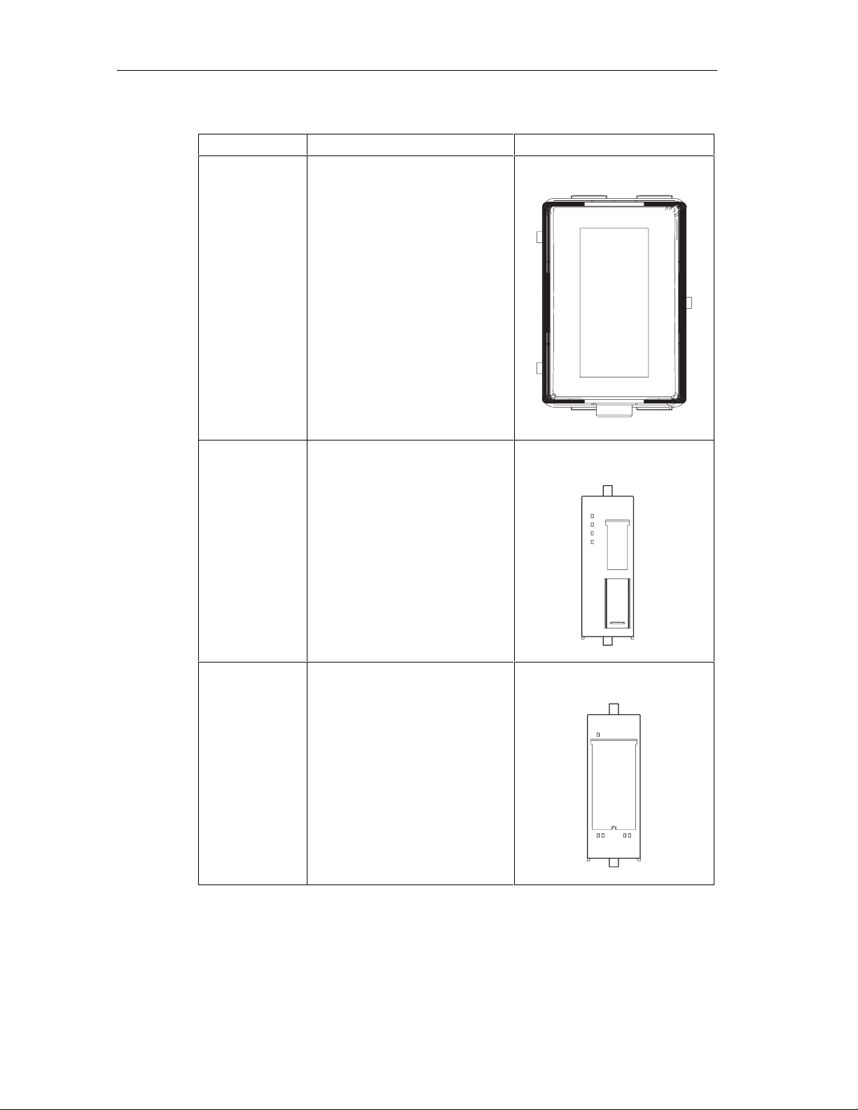
Layout
The following figure shows an example of an ET 200iS configuration.
Power supply
module PS
Terminal module
TM-PS
Figure 2-2 View of the ET 200iS Distributed I/O Station
Components of the ET 200iS
Interface
module IM 151-2
Terminal module
TM-IM
Electronics
module
Terminal modules
TM-E
Bus termination
module
The table below provides you with an overview of the most important components
of the ET 200iS.
Table 2-1 Components of the ET 200iS
Component Function Appearance
Enclosure ... is an additional measure to
further increase safety avoiding the
production of high temperatures,
sparks and electric arcs.
• Zone 1: Enclosure with degree
of protection EEx e
• Zone 2: Enclosure with at least
degree of protection IP54
ET 200iS Distributed I/O Station
2-4 A5E00087831-02
Page 25
Product Overview
Component Function Appearance
DIN rail ( 35 x 15
mm, tin-plated or
hot-galvanized in
compliance with
DIN 50022)
Terminal module ...carries the wiring and
... is the rack of the ET 200iS. You
install the ET 200iS on the DIN rail.
accommodates the power supply
module, interface module, and the
electronics modules. The following
types of terminal modules are
available:
• for the power supply module
TM-PS
• for the interface module TM-IM
• for the electronics modules TM-
E
Terminal module TM-PS
ET 200iS Distributed I/O Station
A5E00087831-02
Terminal module
TM-IM
Terminal module
TM-E
2-5
Page 26
Product Overview
Component Function Appearance
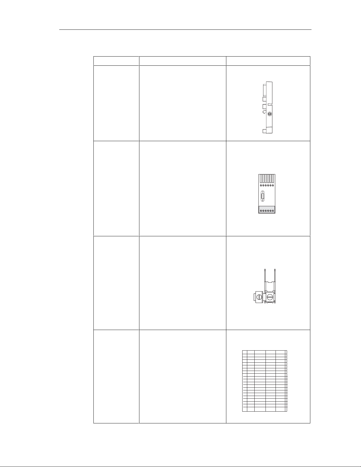
Power supply
module
Interface module ... is plugged onto the terminal
... is plugged onto the terminal
module
TM-PS. The power supply module
supplies the electronics and
encoders with voltage.
module
TM-IM. The interface module
connects the ET 200iS with the DP
master and conditions the data for
the inserted electronics modules.
Electronics
module
... is plugged onto the terminal
module
TM-E and decides which function
is performed:
• Digital electronics modules for
NAMUR encoders, digital
output
• Analog electronics modules
with current and resistance
measurement, thermoresistors
and thermocouples
• Analog electronics modules
with HART, analog output
ET 200iS Distributed I/O Station
2-6 A5E00087831-02
Page 27
Product Overview
Component Function Appearance
Bus termination
module
...completes the ET 200iS.
Fieldbus isolating
transformer
Shield contact ...used to contact cable shields.
...converts PROFIBUS-DP to
PROFIBUS-DP Ex i
Label sheet (DIN
A4, perforated,
foil)
ET 200iS Distributed I/O Station
A5E00087831-02
...for machine labeling or printing;
80 strips per sheet
2-7
Page 28
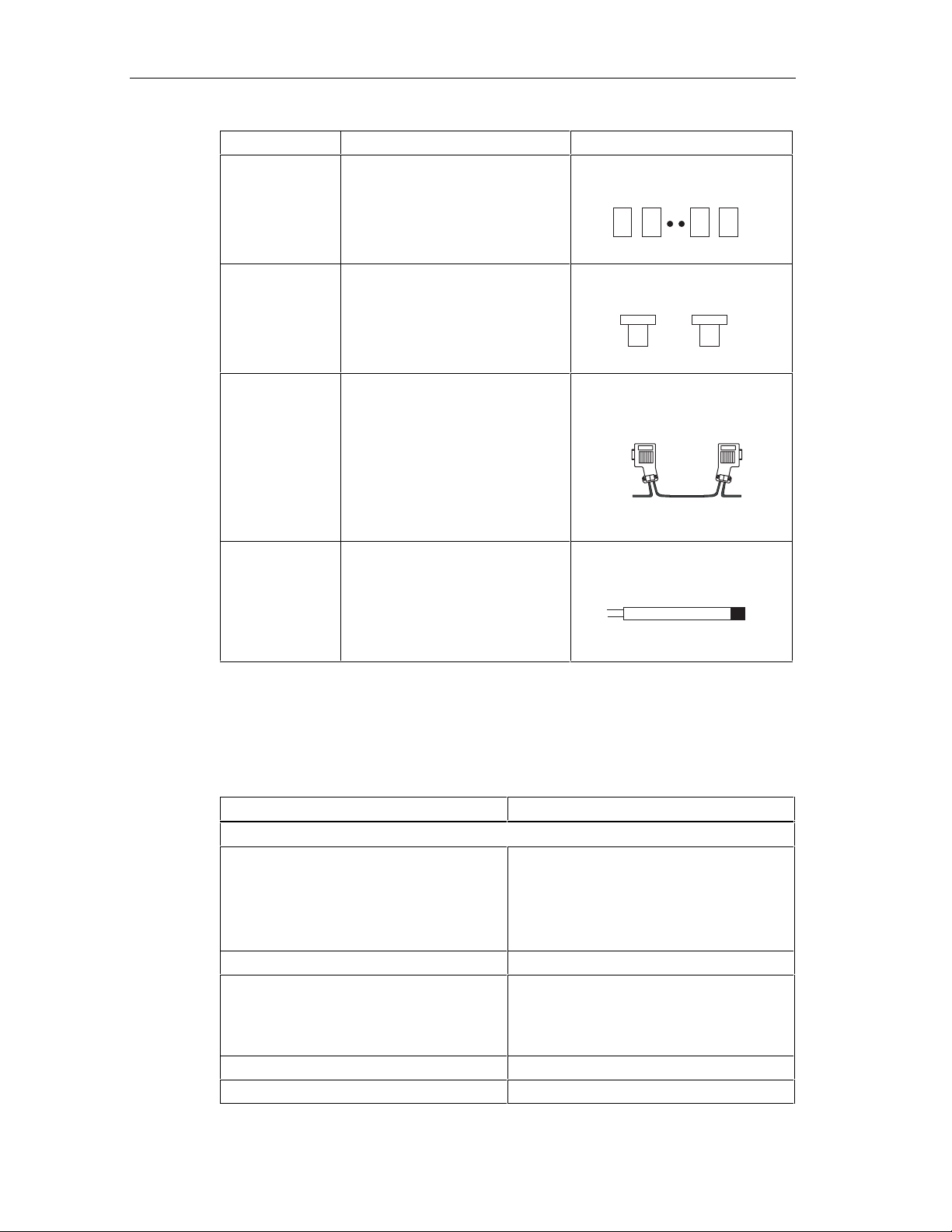
Product Overview
Component Function Appearance
Slot number
labels
Color labels ...allow customer and country-
...for identifying the slots on the
terminal module
specific identification of the
terminals on the terminal module
1
2
31
32
PROFIBUS cable
with bus
connector
...interconnects the nodes of a
PROFIBUS-DP Ex i system or
connects the fieldbus isolating
transformer with the ET 200iS.
Bus terminating
...terminates PROFIBUS-DP Ex i
resistor
Properties and Uses of the ET 200iS
Table 2-2 Properties and Uses
Features Uses
Scalable modular design with 2 or 4-channel
electronics modules
Wide range of electronics modules Extensive area of application
Permanent wiring by separating mechanical
and electronic components
Integrated powerbus Reduced wiring effort
Screw or spring terminals Use of most suitable terminating technique
The design
• Station design optimized to contain costs
• Reduced configuration and
documentation effort
• Space-saving with no fixed order for the
modules
• Prewiring possible
• Hot swapping of modules while the ET
200iS is operating when at least two
electronics modules are present.
2-8 A5E00087831-02
ET 200iS Distributed I/O Station
Page 29

Product Overview
Features Uses
Terminals and Connections
Intrinsically safe inputs and outputs
complying with EEx ia IIC T4 and EEx ib IIC
T4.
Terminal box in terminal module can be
replaced
Automatic coding of the I/O modules Fast and safe module replacement
Large labels Adequate space for clear labeling
Functionality
Changing parameter settings during
operation
Time stamping, flutter monitoring, pulse
stretching
Identification data Unique identification/assi gnm ent of the
Intrinsically safe encoders, actuators and
HART field devices from zone 0, 1, and 2
can be connected
No need to remove the terminal module if
terminals are damaged
No restart of the ET 200iS necessary
Efficient monitoring of the inputs
modules used (for example, for validation,
quality assurance)
DP master
All modules of the ET 200iS can communicate with all DP masters that comply with
the IEC 61158/EN 50170, Volume 2, PROFIBUS standard.
2.3 ET 200iS in the Hazardous Area
Properties of the Zones
Areas in which there is a risk of explosion are divided into zones. The zones are
distinguished according to the probability of the existence of an explosive
atmosphere.
The ET 200iS can be used in hazardous areas in zone 1, zone 2 (division 2) and in
the safe area.
You can connect intrinsically save encoders, actuators, and HART field devices to
the ET 200iS that are permitted in zone 0, zone 1, zone 2 of the hazardous area
and in the safe area. The encoders, actuators, and HART field devices must be
certified for the relevant zones.
ET 200iS Distributed I/O Station
A5E00087831-02
2-9
Page 30
Product Overview
The following table provides an overview of the zone categories:
Table 2-3 Classification of Zones
Zone Degree of Hazard Example
0 Explosive atmo sphere is continuously
present or present for long periods or
often present
1 Explosive gas atm osp here is
sometimes present
2 Explosive gas atm osphere is seldom
present and then only for a short time
Safe area No Standard Applications or
Types of Protection of the ET 200iS
Within containers.
In the region of openings for filling
and emptying.
Areas bordering on zone 1
distributed I/O
The types of protection include design and electrical measures relating to the
equipment to achieve explosion protection in the hazardous areas .
The ET 200iS has the following types of protection:
Properties and Types of Protection
The types of protection of the ET 200iS have the following significance:
Table 2-4 Properties and Types of Protection
Type of
Protection
Intrinsic safety i All voltages, currents, inductance
and capacitance occurring are
limited by electrical measures
(intrinsically safe) - sparks or
thermal effects capable of causing
ignition cannot occur.
Meaning Representation
2-10 A5E00087831-02
ET 200iS Distributed I/O Station
Page 31

Product Overview
Type of
Protection
Explosion-proof
enclosure d
Increased-safety
enclosure e
Meaning Representation
The power supply module is
installed in a stable (explosionproof) enclosure. If the explosive
atmosphere within the enclosure
ignites, the enclosure will withstand
the explosion and contain the
explosion within the power supply
module.
In zone 1 of the hazardous area,
the ET 200iS must be installed in
an additional enclosure. The
enclosure must have the increased
safety e type of protection.
This type of protection involves
additional measures to avoid the
occurrence of high temperatures,
sparks and arc-over.
In zone 2 of the hazardous area,
this type of protection is
unnecessary. Here, the ET 200iS
must simply be installed in an
enclosure suitable for zone 2 with
at least degree of protection IP 54.
ET 200iS Distributed I/O Station
A5E00087831-02
2-11
Page 32

Product Overview
Identification Codes of the ET 200iS
All equipment intended for use in hazardous areas must have an identification
code indicating the type of hazardous environment for which the equipment is
suited.The ET 200iS has the following types of identification code:
Power supply
module:
EEx de [ia/ib]
IIC/IIB T4
PROFIBUS-DP Ex i
Hazardous area: zone 1
Enclosure: EEx e
ET 200iS: EEx ib IIC T4
Terminals:
EEx ib IIC T4 and EEx ia IIC T4
Hazardous area: zone 2
Key:
Eex:
Explosion-protection identifier
ib:
Type of protection: intrinsic safety (use of the ET 200iS in zone 1)
ia:
Type of protection: intrinsic safety (use of sensors, actuators, HART field devices
up to zone 0)
: T
ype of protection: explosion-proof enclosure
d
:
Type of protection: increased safety
e
IIC:
Explosion group for hydrogen
IIB:
Explosion group for ethylene
Figure 2-3 Identification Codes of the ET 200iS
mA
2-12 A5E00087831-02
ET 200iS Distributed I/O Station
Page 33

2.4 Integration in Process Control System
PCS 7
PCS 7 is a powerful process control system. Through PCS 7, the ET 200iS has a
direct attachment to the control system.
Product Overview
Components of PCS 7
Higher level
Lowest level:
actuators, sensors,
field devices
Industrial Ethernet
S7-400
PC
PCS7-OS
PC
PCS7-ES
Operator control and
monitoring with WinCC
Configuration with
STEP7
Parameter assignment
with SIMATIC PDM
PROFIBUS DP
Fieldbus isolating transformer
PROFIBUS-DP EX i
ET 200iS in enclosure
Hazardous area:
zone 1
Figure 2-4 Integration in the Control System
ET 200iS Distributed I/O Station
A5E00087831-02
Zone 0
mA
Hart
2-13
Page 34

Product Overview
2-14 A5E00087831-02
ET 200iS Distributed I/O Station
Page 35

3Brief Instructions on Commissioning
3.1 Introduction
Introduction
This manual guides you step-by-step through a concrete example until you have
created a functioning application. While working through the example, you will learn
the basic hardware and software functions ET 200iS.
3.2 Requirements
Requirements
The following requirements must be met:
3
• You must be familiar with the basics of electrical and electronic engineering and
the procedures relating to hazardous areas as well as experience of working
with computers and Microsoft(R) Windows(TM) 95/98/ME/NT/2000.
• Full versions of STEP 7 and SIMATIC PDM (Version 5.1, Service Pack 2, Hotfix
1 or higher) are installed on your PG and you are familiar with the basics of
working with STEP 7. Older versions of STEP 7 can also be used. See
Commissioning and Diagnostics
• If you implement this example in zone 1 or zone 2, you must adhere to all the
rules and regulations explained and listed in this manual.
Note
When checking the functionality make sure that you keep to the stipulations in
EN 60 079-17. This standard contains the regulations of the international standard
IEC 60 079-17.
Danger
When laying cables and wiring, make sure that you adhere to the installation
regulations complying with EN 60 079-14 and any regulations specific to your
country.
ET 200iS Distributed I/O Station
A5E00087831-02
3-1
Page 36

Brief Instructions on Commissioning
Warning
When used in systems, the ET 200iS is subject to special rules and regulations
depending on the area of applicat ion.
Please note and adhere to the valid safety and accident prevention regulations, for
example IEC 204 (EMERGENCY STOP devices).
If you do not adhere to these regulations, this can result in serious injury and
damage to machines and facilities.
3.3 Materials and Tools Required to Set Up the Example
Table 3-1 Required Material and Tools
Number Article Order Number (Siemens)
2 Rails complying with EN 50022 (35 x 15 mm) e.g. 6ES5 710-8MA11
1 Enclosure for ET 200iS with degree of protection EEx e Contact your Siemens
representative
1 Terminal module TM-PS 6ES7 193-5DA00-0AA0
1 Terminal module TM-IM with bus termination module 6ES7 193-5DB00-0AA0
7 Terminal module TM-E30S44-iS 6ES7 193-5CB00-0AA0
1 Interface module IM 151-2 6ES7 151-2AA0-0AB0
1 Power supply PS 6ES7 138-5EA00-0AA0
3 4DI NAMUR 6ES7 131-5RD00-0AB0
3 2DO DC25V/25mA 6ES7 132-5SB00-0AB0
1 EEx e-terminal WPE 16/E 17522900 (manufacturer
Weidmüller)
1 Fieldbus isolating transformer 9373 with terminating
resistor
2 PROFIBUS bus connector (for master) 6ES7 972-0BB10-0XA0
1 PROFIBUS bus connector (for ET 200iS) 6ES7 972-0BA30-0XA0
1 PROFIBUS-DP cable e.g. 6XV1 830-0EH10
2 NAMUR sensor e.g. BERO 3RG 4612-1NA00
1 1-wire On button normal suppliers
3 LEDs with series resistor normal suppliers
1 Power supply module PS S7-400 e.g. 6ES7 405-0KA00-0AA0
1 CPU S7-416-3 DP 6ES7 416-3XL00-0AB0
1 Rack for S7-400 e.g. 6ES7 400-1TA01-0AA0
1 Programming device (PG) with PROFIBUS-DP interface,
installed software STEP 7 (Version 5.1, Service Pack 2,
Hotfix 1 or higher) communications processor CP 5611
and PG cable
1 Screwdriver with 3 mm blade normal suppliers
Can be ordered from
R. Stahl Schaltgeräte GmbH
order number 93 730 05 01 2
various
3-2 A5E00087831-02
ET 200iS Distributed I/O Station
Page 37

Brief Instructions on Commissioning
Number Article Order Number (Siemens)
1 Screwdriver with 7 mm blade normal suppliers
1 Cutting tool for the DIN rails normal suppliers
1 Cable cutters and wire stripping tools normal suppliers
1 Tool for crimping wire-end ferrules normal suppliers
X m Cable for grounding DIN rails with 10 mm cross-section
with terminal end to fit M6, length to suit local situation
approx.
2 m
Flexible lead with 1 mm2 cross section and suitable wireend ferrules, form A, length 6 mm
normal suppliers
normal suppliers
3.4 Overview of the Setup
Overview of the Example Setup (wiring and power sources not illustrated)
S7-400
Fieldbus
isolating
transformer
PG with CP 5611
Enclosure EEx e
Ground bus PA
3x 4 DI NAMRUR
3x 2DO
ET 200iS
Terminating resistor
Figure 3-1 Overview of the Example Setup
ET 200iS Distributed I/O Station
A5E00087831-02
3-3
Page 38

Brief Instructions on Commissioning
3.5 Setting Up the Configuration for the Example
3.5.1 Setting up the ET 200iS
1. Install the DIN rail (483 mm) in the EEx e enclosure EEx e, that is secured to a
firm base. See also Section: Installation.
2. Start to install the modules starting at the left of the rail. Begin with the terminal
module TM-PS (fit onto rail – push in). Continue with the rest of the modules (fit
onto the rail – push in – slide left).
Make sure you install in the order shown below:
– Terminal module TM-PS
– Terminal module TM-IM
– 6x terminal module TM-E30S44-iS
– Bus termination module
3.5.2 Setting Up the S7-400
1. Install the rack on a stable surface. See also the manual: Installing an S7-40 0.
2. Start installing the individual modules in the rack from the left (fit to the rail –
push in – secure the screws). Make sure you install in the order shown below:
– Power supply PS
– CPU S7-416-3 DP
3.5.3 Installing the Fieldbus Isolating Transformer
1. Install the second DIN rail on a firm surface.
2. Fit the fieldbus isolating transformer onto the rail and push it in.
Note
Install the fieldbus isolating transformer in an enclosure outside the hazardous
area and check the settings (DIP switches) on the fieldbus isolating transformer
based on the accompanying operating instructions.
3-4 A5E00087831-02
ET 200iS Distributed I/O Station
Page 39

3.6 Wiring the Example Setup
Brief Instructions on Commissioning
Terminal module TM-PS
for power supply
module PS
Figure 3-2 Wiring TM-PS
DC 24V
1L+
2L+
1M
2M
1PA
2PA
RL+
RM
To ground bus PA
ET 200iS Distributed I/O Station
A5E00087831-02
3-5
Page 40

Brief Instructions on Commissioning
To S7-416-3 DP
-
L1
L2
+
-
+
DC 24V
Fieldbus
isolating transformer
Shield
Terminating resistor:
ON
red
green
To ET 200iS
Figure 3-3 Wiring Fieldbus Isolating Transformer
Safe interface: RS-485
Intrinsically safe interface: RS-485
Transmission rate: 1.5 Mbps
Connect the following:
1. the programming device (PG) and the S7-416-3 DP-CPU (interface: X1 MPI)
with a PG cable
2. the S7-416-3 DP CPU (interface: X3 DP) with the fieldbus isolating transformer,
as shown above, with a PROFIBUS-DP cable (use PROFIBUS bus connector
6ES7 972-0BB10-0XA0)
3. the interface module IM 151-2 with the fieldbus isolating transformer as shown
above using a PROFIBUS-DP cab le (use a PRO FIBUS bus connector
6ES7 972-0BA30-0XA0)
3-6 A5E00087831-02
ET 200iS Distributed I/O Station
Page 41

Brief Instructions on Commissioning
4. the terminating resistor supplied with the fieldbus isolating transformer, with the
interface module IM 151-2
5. the power supply PS, the fieldbus isolating transformer, and the power supply
PS S7-400 with the power supply
6. the rack of the S7-400 with the grounding conductor
7. the DIN rail of the ET 200iS and the power supply module PS with the
equipotential bonding system PA. To secure to the DIN rail, use the EEx eterminal.
Wire the ET 200iS as shown below:
3x 4DI NAMUR
clamp
1
2
2
NAMURencoder
1
2
Figure 3-4 Wiring the ET 200iS Modules
3x 2DO
3
1
4
3
3
4
LEDs
4
ET 200iS Distributed I/O Station
A5E00087831-02
3-7
Page 42

Brief Instructions on Commissioning
3.7 Insert the interface module and the electronics modules
Start at the left by inserting the electronics modules. See also: Inserting and
Labeling the Power Supply, Interface Module, and Electronics Modules.
Make sure you install in the order shown below:
• Power supply PS
• Interface module IM 151-2
• 3x 4DI NAMUR
• 3x 2DO DC25V/25mA
3.8 Setting the PROFIBUS Address
On the IM 151-2 interface module, set PROFIBUS address 3. See also: Setting the
PROFIBUS Address.
Interface module
Figure 3-5 Setting PROFIBUS Address 3
OFF
64
32
16
*
ON
8
4
2
1
Example:
DP address=
+2
+1
_______
=3
* Intended for future expansion.
Switch must be set to OFF.
3-8 A5E00087831-02
ET 200iS Distributed I/O Station
Page 43

3.9 Configuring the Example
3.9.1 Configuring the S7-400
Step 1
Open STEP 7.
Step 2
If the New Project Wizard opens, close it with Cancel.
Step 3
Go to the main menu of the SIMATIC Manager and select File > New. A dialog box
opens in which you enter "ET 200iS" as the name and then close the dialog with
OK.
Brief Instructions on Commissioning
Step 4
Step 5
Step 6
Step 7
ClickInsertClick Insert > Station in the menu and select SIMATIC 400 Station
from the list. An icon with the name SIMATIC 400(1) is created in the right-hand
pane of the project window.
Now double-click on the icon of the SIMATIC 400 station in the SIMATIC Manager.
An icon labeled "Hardware" now appears in the right-hand pane of the window.
Double-click on this icon. HW Config opens.
If no catalog with components is displayed on the right-hand side of the window,
activate the display by selecting View > Catalog in the menu.
Expand the SIMATIC 400 folder and RACK-400 folder until you can see UR1.
Double-click on this icon. In the lower part of the window on the left, you can now
see the slots.
Select slot 1 (it changes to blue) and then return to the catalog and open the
folders SIMATIC 400, PS 400 and Standard PS 400 until you can see PS 407 10A.
Double-click on this icon. The power supply module now occupies slots 1 and 2.
ET 200iS Distributed I/O Station
A5E00087831-02
3-9
Page 44

Brief Instructions on Commissioning
Step 8
Next, select slot 3 and then return to the catalog and open folders SIMATIC 400,
CPU 400, CPU 416-3 DP and 6ES7 416-3XL00-0AB0 until you can see V1.2.
When you double-click on the icon, a window with the title "Properties - PROFIBUS
interface DP R0/S3.1)“ opens and you can acknowledge this window with OK. The
CPU is entered in slots 3 and 4.
Step 9
In the lower left-hand window, locate the row labeled DP and select it. Right-click
on the row and select Object Properties. The "Properties DP (R0/S3.1)" dialog
opens. Click the Properties button and in the next dialog, click New. A new DP
subnet operating at 1.5 Mbps is created. Now confirm by clicking OK three times in
succession.
Step 10
In the main menu, you can save the changes with Station > Save and Compile.
Figure 3-6 Configuration of the S7-400
3-10 A5E00087831-02
ET 200iS Distributed I/O Station
Page 45

3.9.2 Configuration of the ET 200iS
Step 1
In the upper left-hand window of HW Config, click on the stylized PROFIBUS to
select it. Now go to the catalog and open PROFIBUS DP and ET 200iS so that you
can see IM 151-2. Double-click on this icon to insert an ET 200iS station. In the
dialog box that opens, change the address to 3 and confirm with OK. At the bott om
left, you can now see the new slots with an IM 151-2 in slot 2.
Step 2
Select slot 1 and then go the catalog to power module PS, which is located under
IM 151-2 in the tree, and insert this by double-clicking on it.
Brief Instructions on Commissioning
Step 3
Since slot 3 must remain free, select slot 4 and starting from there insert three
NAMUR 4DI modules and three 2DO DC25V/25mA modules.
ET 200iS Distributed I/O Station
A5E00087831-02
3-11
Page 46

Brief Instructions on Commissioning
Step 4
Figure 3-7 Configuration of the ET 200iS
After saving the project with the menu command Station > Save and Compile,
you can exit HW Config.
3-12 A5E00087831-02
ET 200iS Distributed I/O Station
Page 47

3.9.3 Setting Parameters for the ET 200iS
Requirements
To be able to work online with SIMATIC PDM, you must set the CP 5611 to the
PROFIBUS-DP interface (in the SIMATIC Manager: menu command Options >
Set PG/ PC Interface).
Step 1
You are still in HW Config. Double-click on the first module in the configuration
table (slot 4: 4DI NAMUR).
Step 2
In the next dialog, select "Specialist" as the user and confirm with "OK". In this
mode, you can make parameter settings.
Brief Instructions on Commissioning
Step 3
Result: SIMATIC PDM is started with the parameters and identification data of the
module.
For channels 1-3 change the encoder type to "channel disabled" and save the
changes with File > Save. With Device > Download to Device, you can download
the parameters to the ET 200iS. Close SIMATIC PDM.
Figure 3-8 Disabling ET 200iS Channels
ET 200iS Distributed I/O Station
A5E00087831-02
3-13
Page 48

Brief Instructions on Commissioning
Step 4
Follow the same procedure as described in points 1 through 3 for each of the ET
200iS modules and make the changes as outlined in the table below.
Table 3-2 Changes
ModuleSlot Type Channel 0 Channel 1 Channel 2-3
1 4 4xDI NAMUR No change Encoder type: Channel
disabled
2 5 4xDI NAMUR No change Encoder type: Channel
disabled
3 6 4xDI NAMUR No change Encoder type: Channel
disabled
4 7 2xDO No change No change 5 8 2xDO No change No change 6 9 2xDO No change No change -
Note
If you double-click on the DP slave "IM 151-2" (in the upper part of the station
window) in HW Config, SIMATIC PDM starts and all the modules of the ET 200iS
are downloaded. If you then select the menu command Device > Full Upload to
PG/PC all the parameters and identification data of the ET 200iS are loaded. In
SIMATIC PDM, you can select individual modules, assign the parameters for them,
and save them (menu command File > Save) and download them to the ET 200iS
(Menu command Device > Full Download to Device).
Encoder type: Channel
disabled
Encoder type: Channel
disabled
Encoder type: Channel
disabled
3.10 Programming the Example
How it Works
The state of the encoders connected to inputs I512.0 , I513.0 and I514.0 is queried
and evaluated. I512.0 increments an internal counter and I513.0 decrements it.
Input I514.0 resets the counter to zero.
Depending on the counter value, outputs Q512.0, Q513.0 and Q514.0 are set or
deleted. Q512.0 is set when the counter value is 0. At a counter value < 3, Q514.0
is set and at ≥ 3, Q513.0 is set.
3-14 A5E00087831-02
ET 200iS Distributed I/O Station
Page 49

Programming
Change to the component view with View > Component View.
Open the following in succession: SIMATIC 400(1), CPU 416-3 DP, S7 Program(1)
and Blocks until you can see OB1. Double-click on OB1 and confirm the dialog with
OK.
Enter the following STL program:
Table 3-3 Program for the Example
STL Remarks
A I 514.0 If button 514.0 is active,
R C 0 set counter to 0
A I 512.0 If BERO 512.0 is active,
CU C 0 increment by 1
A I 513.0 If BERO 513.0 is active
CD C 0 decrement by 1
Brief Instructions on Commissioning
AN C 0 Is counter = 0 ?
= Q 512.0 YES, then output 512.0 is active
L C 0 Load counter in ACCU
L 3 Load 10 in ACCU
>=I Is counter => 3 ?
= Q 513.0 YES, then output 513.0 is active
<I Is counter < 3 ?
= Q 514.0 YES, then output 514.0 is active
Save the program with File > Save and download it to the CPU withPLCwith PLC
> Download.
ET 200iS Distributed I/O Station
A5E00087831-02
3-15
Page 50

Brief Instructions on Commissioning
3.11 Putting the Example into Operation
Turn on the power supply of the ET 200iS.
Watch the status LEDs on the S7-400 and on the ET 200iS:
• CPU 416-3 DP :
DC 5V: lit
SF DP: off
BUSF: off
• ET 200iS:
SF: off
BF: off
ON: lit
3.12 Evaluating the Diagnostics
If an error occurs, OB82 is started. Evaluate the startup information in OB82.
Tip: Call SFC13 in OB82 and evaluate the diagnostic frame. See Commissioning
and Diagnostics.
3-16 A5E00087831-02
ET 200iS Distributed I/O Station
Page 51

Brief Instructions on Commissioning
3.13 Removing and inserting modules
Removing and Inserting Digital Electronics Module 4 DI NAMUR
1. Remove the first of the three electronics modules 4 DI NAMUR from the
terminal module during operation.
2. Monitor the status LEDs on the IM 151-2:
– SF: lit -> diagnostic message exists
– BF: off
– ON: lit
Result: The ET 200iS continues to operate problem-free.
3. Evaluate the diagnostic m es sage
Result:
– Station status 1 (byte 0): Bit 3 is set -> External diagnostics
– ID-related diagnostics : Bit 3 in byte 7 is set -> slot 4
– Module status: Byte 16.7/16.6: 11
-> no module
B
4. Insert the removed electronics module in the terminal module again
Result:
– Status LEDs IM 151-2:
SF: off
BF: off
ON: lit
– The diagnostic message is deleted
ET 200iS Distributed I/O Station
A5E00087831-02
3-17
Page 52

Brief Instructions on Commissioning
3.14 Wire break of the NAMUR encoder connected to the digital input module
1. Remove the wire from terminal 1 of the first of the three electronics modules
4 DI NAMUR.
2. Monitor the status LEDs
IM 151-2:
– SF: lit
– Electronics module 4 DI NAMUR
– SF: lit -> diagnostic message exists
– 1: off -> output is not activated
3. Evaluate the diagnostic m es sage
Result:
– Station status 1 (byte 0): Bit 3 is set -> External diagnostics
– ID-related diagnostics: Byte 7.3 is set -> slot 4
– Channel-related dia gnos t ics :
Byte 25: 10000011
Byte 26: 01000000
byte 27: 00110
-> slot 4
B
-> channel 0
B
-> wire break
B
4. Secure the wire to the BERO again in terminal 1 and evaluate the diagnostics
again:
– Status LED IM151-2
SF: off
– Status LEDs electronics module 4 DI NAMUR:
SF: off
1: off/on
– The diagnostic message is deleted.
3-18 A5E00087831-02
ET 200iS Distributed I/O Station
Page 53

4Configuration Options
4.1 System with Scalable Modularity
System with Scalable Modularity
With the ET 200iS scalable modularity means that you can adapt the structure
exactly to match your applications with 2 and 4-channel electronics modules.
Example
The following schematic shows an example of a possible configuration of the ET
200iS distributed I/O station:
4
ET 200iS Distributed I/O Station
A5E00087831-02
4-1
Page 54

Configuration Options
Power supply module PS
Switches,
IM 151-2
4DI NAMUR
NAMUR sensors
2/4-wire transducers
Resistance thermometers
2 DO DC25V/25mA
2AI I 2WIRE
2AI I 4WIRE
Relays
Thermocouples
mA
2AI RTD
2AI TC
2AO I
2AI I 2WIRE HART
2AI I 4WIRE HART
2AO I HART
Loads at current output
HART field devices
Figure 4-1 Example of an ET 200iS Configuration
4.2 Electronics Modules to Suit your Application
Which Electronics Module Does What?
In the following table, you will find a guide to the applications of the electronics
modules of the ET 200iS distributed I/O station.
4-2 A5E00087831-02
ET 200iS Distributed I/O Station
Page 55

Electronics Modules to Suit your Application
Table 4-1 Electronics Modules to Suit your Application
Application Electronics Modules
Evaluation of NAMUR encoders
Evaluation of connected, unconnected
mechanical contacts
Switching solenoid valves, d.c. relays,
indicator lamps, actuators
Measuring currents with 2-wire
transducers
Measuring currents with 4-wire
transducers
Measuring currents with HART field
devices (2 wire transducers)
HART communication
Measuring currents with HART field
devices (4-wire transducers)
HART communication
Measuring temperatures with
resistance thermometers
Measuring resistance
Measuring temperatures with
thermocouples
Measuring thermal e.m.f.
Output of currents 2 output channels
Output of currents with HART field
devices
HART communication
4 input channels 4DI NAMUR
2 output channels 2DO DC25V/25mA
2 input channels
Input ranges:
• 4 to 20 mA
2 input channels
Input ranges:
• 0 to 20 mA
• 4 to 20 mA
2 input channels
Input range 4 to 20mA
2 input channels
Input range 4 to 20mA
2 input channels
Input ranges:
• Pt100, Ni100
• 600 ohms
2 input channels
Input ranges:
• ± 80 mV
• Type E, N, S, K, L,
Output ranges:
• 0 to 20 mA
• 4 to 20 mA
Output range 4 to
20mA
Configuration Options
2AI I 2WIRE
2AI I 4WIRE
2AI I 2WIRE HART
2AI I 4WIRE HART
2AI RTD
2AI TC
S, R, B, T, U
2 AO I
2AO I HART
ET 200iS Distributed I/O Station
A5E00087831-02
4-3
Page 56

Configuration Options
4.3 Which Electronics Modules Match the Terminal Modules?
Selecting the Terminal Modules
In the following table, you will find information to help you select the terminal
modules you require.
Which Electronics Modules Match the Terminal Modules?
Table 4-2 Which Electronics Modules Match the Terminal Modules?
Electronics Modules Terminal Modules
Power supply module PS Terminal module TM-PS
Interface module IM 151-2 Terminal module TM-IM
• 4DI NAMUR
• 2DO DC25V/25mA
• 2AI I 2WIRE
• 2AI I 4WIRE
• 2AI I 2WIRE HART
• 2AI I 2WIRE HART
• 2AI RTD
• 2AI TC
• 2 AO I
• 2AO I HART
Bus termination module ---
Terminal module TM-E30S44-iS (screw
terminal)
or
Terminal module TM-E30C44-iS (spring
terminal)
4-4 A5E00087831-02
ET 200iS Distributed I/O Station
Page 57

4.4 Configuration Options in Zones
General Rules
Regardless of the configuration of the ET 200iS in zone 1, zone 2 or in the safe
area, the following rules apply:
If the inputs and outputs to the actuators are intrinsically safe, then
PROFIBUS-DP must also be intrinsically safe (Ex i):
1. Fieldbus isolating transformer required (for example, from R. STAHL
Schaltgeräte GmbH; Refer to the order numbers)
2. Marking of PROFIBUS-DP as Ex i (not only in zone 1!)
3. Marking of the cables/wires to the actuators and sensors as Ex i (for example,
using the color light blue).
Warning
All devices you connect to PROFIBUS-DP Ex i (on the Ex side of the fieldbus
isolating transformer) must be intrinsically safe.
Configuration Options
Connecting voltage measurement devices, oscillographs, and bus testers to
PROFIBUS-DP Ex i is not permitted.
Rules for Configuring the ET 200iS in Zone 1:
If you use the ET 200iS in zone 1, you must adhere to the following rules:
1. The ET 200iS must be installed in an enclosure with type of protection EEx e
(increased safety). For information on ordering such enclosures, contact your
Siemens representative
2. PROFIBUS-DP must be isolated using a fieldbus isolating transformer. The
fieldbus isolating transformer (for example from R. STAHL Schaltgeräte GmbH;
refer to the section Order Numbers) guarantees degree of protection EEx i for
PROFIBUS-DP in hazardous areas (zone 1).
The fieldbus isolating transformer must be installed in the safe area. See
Appendix Order Numbers.
3. Normal PROFIBUS-D P bus cab les can be used in zo ne 1. See app end ix Order
Numbers. You must, however, mark these as "EEx i bus cable" (for example
with a blue band/blue shrink-on sleeve at the ends or mark the cable with a blue
color).
ET 200iS Distributed I/O Station
A5E00087831-02
4-5
Page 58

Configuration Options
4. The PROFIBUS-DP bus cable must be connected to the IM 151-2 over the bus
connectors operating at 1.5 Mbps (order number 6ES7 972-0BA30-0XA0).
5. PROFIBUS-DP Ex i must be terminated in zone 1 with the RS-485 terminating
resistor (included with the fieldbus isolating transformer). The maximum length
(total length of PROFIBUS-DP cabling) is 200m.
Safe
area
PROFIBUS-DP
bus cable
PROFIBUS-DP
Ex i
Enclosure type of protection EEx e
Bus connector 1.5 Mbps
Figure 4-2 Configuration Options for the ET 200iS in Zone 1
Fieldbus isolating transformer
Hazardous area: zone 1
ET200iS
Rules for Configuring the ET 200iS in Zone 2:
If you use the ET 200iS in zone 2, you must adhere to the following rules:
1. The ET 200iS must be installed in an enclosure with at least degree of
protection IP 54. The enclosure must have a manufacturer's certification for
zone 2 (complying with EN 50021: Protection from mechanical damage; degree
of protection IP 54; avoidance of ignition due to electrostatic charge).
RS-485
terminating resistor
Enclosure type of protection EEx e
ET200iS
2. See points 2 to 5: Rules for Configuring the ET 200iS in Zone 1
Rules for Configuring the ET 200iS in the Safe Area:
If you use the ET 200iS in the safe area, you must adhere to the following rules:
1. The ET 200iS must be installed in a metallic enclosure with at least degree of
protection IP 20.
2. See points 2, 4 and 5: Rules for Configuring the ET 200iS in Zone 1
4-6 A5E00087831-02
ET 200iS Distributed I/O Station
Page 59

Configuration Options
Rules for Configuring Encoders, Actuators, HART Field Devices in Zone 1 and
Zone 0
The verification of intrinsic safety for each field circuit must be made according to
the regulations stipulated by the relevant standards for configuration, selection and
installation.
A simple, intrinsically safe circuit results from attaching an encoder, actuator or
HART field device to an input or output of an electronics module.
The following table describes the conditions for checking the maximum safe values
for a simple, intrinsically safe circuit:
Table 4-3 Rules for Configuration
Relevant Standard / Conditions for
Electrical Parameters
Standard: EN 60 079-14
The electrical parameters must be as
follows:
≤ U
• U
o
i
• Io ≤ I
• Po ≤ P
• Co ≥ Ci + C
• Lo ≥ Li + L
i
i
cable
cable
ET 200iS modules
Sensors
actuators
HART field devices
Usable Encoders and Actuators
The maximum safe values of the encoders
and actuators must be adapted to the
maximum values of the electronics modules.
You will find these maximum values
• in the Ex certification of the encoders
and actuators
• in the technical specifications of the
electronics modules of the ET 200iS
U max. output voltage
0
I max. output current
0
P max. output power
0
C max. external capacitance
0
L max. external inductance
0
C max. capacitance wire/cable
cable
L max. inductance wire/cable
cable
U max. input voltage
i
I max. input current
i
P max. input power
i
C max. internal capacitance
i
L max. internal inductance
i
ET 200iS Distributed I/O Station
A5E00087831-02
4-7
Page 60

Configuration Options
Safety-Related Notices
Note
During configuration, make sure that you keep to the stipulations in EN 60 079-14.
See table above.
Warning
Connecting an intrinsically safe sensor, actuator, or HART field device to the
input/output of an electronics module must produce an intrinsically safe circuit! For
this reason:
When you select the encoder, actuator, or HART field device to be connected to
the electronics module, the resulting safety-related values must be checked!
The inductance and capacitance of the cable must also be taken into account!
4.5 Power Supply of the ET 200iS
Power supply PS
Connect the power supply of the ET 200iS to the TM-PS terminal module of the
power supply module PS. The power supply module PS provides the required
output voltages for the ET 200iS. The output voltages are electrically isolated from
the supply voltage and intrinsically safe.
• Electronics of the IM 151-2/ backplane bus
• PROFIBUS-DP Ex i interface
• Powerbus
4-8 A5E00087831-02
ET 200iS Distributed I/O Station
Page 61

Configuration Options
Power supply
DC 24 V
Grounding
conductor PA
Figure 4-3 Power Supply Module PS
Powerbus
The electronics modules are supplied with the necessary supply and rated load
voltages over the powerbus.
4.6 Direct Data Exchange
Output voltage for powerbus
Electronics IM 151-2/backplane bus
PROFIBUS-DP-Ex i interface
Requirements
The ET 200iS can be used as publisher for direct data exchange (cross
communication). This requires no configuration.
Naturally, the DP master used must also support direct data exchange. You will
find information on this in the description of the DP master.
Principle
The main feature of direct data exchange is that PROFIBUS-DP nodes "listen in"
and know which data a DP slave returns to its DP master. With this mechanism,
the "listener" (recipient) can access changes to the input data of remote DP slaves
directly.
During configuration in STEP 7, you use the peripheral input addresses to specify
the address area of the recipient in which the required data of the publisher will be
read.
ET 200iS Distributed I/O Station
A5E00087831-02
4-9
Page 62

Configuration Options
Example
The schematic below illustrates the direct data exchange "relationships" that you
can configure with an ET 200iS as publisher and which nodes can "listen in" as
potential recipients.
DP master
CPU 31x-2
PROFIBUS-DP Ex i
ET 200iS
Figure 4-4 Example of Direct Data Exchange
system 1
CPU 31x-2 as
DP master 1
ET 200iS
DP master
system 2
CPU 31x-2 as
DP master 2
DP slave
ET 200iS
CPU 31x2asDP
slave
4.7 Using the ET 200iS in a Redundant Standard DP Master System
Features
The ET 200iS can be included in a redundant DP standard master system as a
DPV0 slave using the Y-Link.
Requirements
• STEP 7
• GSD file
• SIMATIC PDM
4-10 A5E00087831-02
ET 200iS Distributed I/O Station
Page 63

IM 157
Configuration Options
Redundant standard DP master system
Redundant PROFIBUS-DP
Y-Link
ET 200MET 200M
Y-chain
Procedure
Distributed
1/0 devices
Zone 1
Figure 4-5 ET 200iS and the Y-Link
Fieldbus isolating transformer
EEx e
Terminating resistor
ET 200iS
1. Configure the redundant DP standard master system (redundant DP master,
PROFIBUS-DP, slaves)
2. Configure the ET 200iS with the GSD file (DPV0 slave)
3. Make the parameter settings for the ET 200iS with SIMATIC PDM.
ET 200iS Distributed I/O Station
A5E00087831-02
4-11
Page 64

Configuration Options
Restrictions
• The ET 200iS can only be configured as a DPV0 slave;
in other words,
– no time stamp
– no interrupts
– no support by the PCS 7 drivers supplied with PCS 7. If you want to include
the ET 200iS into PCS 7, you must create your own drivers.
• Configuration is in two stages (with the GSD file and SIMATIC PDM):
It is not possible to exchange the data of the configuration between STEP 7 and
SIMATIC PDM.
• The transfer of the diagnostic messages of the ET 200iS to the DP master is
restricted (only the module status per module, no channel-related diagnostics).
Reference
You will find further information in the documentation on the Y-Link (manual or
product information bull eti n).
4.8 Restricted Number of Connectable Electronics Modules/Maximum Configuration
Number of ET 200iS Stations
You can operate a maximum of 16 ET 200iS stations on one chain of PROFIBUSDP Ex i (over a fieldbus isolating transformer).
4-12 A5E00087831-02
ET 200iS Distributed I/O Station
Page 65

Number of Electronics Modules
Each ET 200iS station consists of a maximum of 32 electronics modules. These
include digital and analog electr on ic s modules.
The actual number of electronics modules is limited by the current of the power
supply module PS.
The limit value for the maximum permitted current is < 4300 mA. This value
must not be exceeded.
• ET 200iS with up to 15 electronics modules:
The current consumption is < 4300 mA. The configuration is OK.
• ET 200iS with 16 to 32 electronics modules:
You must check the maximum current consumption of the electronics modules
using the following calculation table:
– Multiply the current consumption per module by the number of modules and
enter the values in the columns x Number of Modules and = Current
Consumption in mA .
– Add all modules and enter the value in the Total Modu les box (maximum of
32 electronics modules)
Configuration Options
– Add the current consumption and enter the value in the Total Current
Consumption box (< 4300 mA)
Table 4-4 Calculation Table for Current Consumption
Electronics
Modules
2DO DC25V/25mA x =
2AI I 2WIRE x =
2AI I 2WIRE HART x =
2 AO I x =
2AO I HART
4DI NAMUR 140 mA x =
2AI I 4WIRE x =
2AI I 4WIRE HART x =
2AI RTD x =
2AO TC
Current
Consumption
per Module in
mA
280 mA
70 mA
x Number of
Modules
Enter the values in these columns!
x=
x=
Total Modules
=
max. 32 modules < 4300 mA
= Current Consumption in
Total Current Consumption
=
mA
ET 200iS Distributed I/O Station
A5E00087831-02
4-13
Page 66

Configuration Options
• Example
An ET 200iS consists of 10 x 4DI NAMUR modules, 7 x 2DO DC25V/25mA
modules and 10 x 2AI I 4WIRE modules.
This configuration therefore consists of 30 electronics modules; in other words,
you must calculate the current consumption (16 to 32 electronics modules):
Table 4-5 Example of a Calculation Table for Current Consumption
Electronics
Modules
2DO DC25V/25mA x 7 = 1960 mA
2AI I 2WIRE x =
2AI I 2WIRE HART x =
2 AO I x =
2AO I HART
4DI NAMUR 140 mA x 10 = 1400 mA
2AI I 4WIRE x 10 = 700 mA
2AI I 4WIRE HART x =
2AI RTD x =
2AO TC
Current
Consumption
per Module in
mA
280 mA
70 mA
x Number of
Modules
Enter the values in these columns!
x=
x=
Total Modules
= 27 modules
max. 32 modules < 4300 mA
= Current Consumption in
Total Current Consumption
= 4060 mA
The configuration is OK
mA
Current Consumption of the ET 200iS with its Maximum Configuration
See Technical Specifications of the Power Supply Module PS.
Width of the ET 200iS:
The maximum width of the ET 200iS is 1.17 m (power supply module + interface
module + 32 electronics m odules ).
Address Space:
The maximum address space depends on the DP master you are using. The
interface module supports a maximum of 128 input and 128 output bytes.
4-14 A5E00087831-02
ET 200iS Distributed I/O Station
Page 67

5Installation
5.1 Rules for Installation
Safety-Related Notices
Danger
During installation, make sure that you keep to the stipulations in EN 60079-14.
The conditions for the electrical parameters in the standard apply to simple
electrical circuits. See section Configuration Options.
Danger
In some circumstances, sparks or unacceptable surface temperatures capable of
ignition can occur during installation.
Never install when an explosive atmosphere is present!
5
The following activities/jobs are forbidden when the ET 200iS is operating and the
DC 24 V power supply is applied to the terminal module TM-PS:
Disconnecting the DC 24V power supply and the terminal module TM-PS.
Uninstalling the bus termination module and any other modifications that affect the
configuration of the terminal modules.
Releasing the screw terminal element on the terminal module TM-PS and on the
bus termination module. The screw terminal element on the terminal module TMPS and on the bus termination module lock the ET 200iS in position mechanically.
ET 200iS Distributed I/O Station
A5E00087831-02
5-1
Page 68

Installation
Installation Dimensions
Table 5-1 Installation Dimensions
Width
Height
Depth ET 200iS on DIN rail with depth of 15 mm 176.2 mm
Dimensions
Terminal module with power supply module 165 mm
Terminal module with interface module 30 mm
Terminal modules with electronics modules 30 mm
Bus Termination Module 12.5 mm
Terminal module with power supply module 200 mm
Terminal module with interface module 132 mm
Terminal modules with electroni cs mo dule s 132 mm
Bus Termination Module 106.2 mm
Enclosure for the ET 200iS in Zone 1
The ET 200iS must be installed in an enclosure with type of protection EEx e
(increased safety). For information on ordering such enclosures, contact your
Siemens representative
Use the following cable glands:
• Power supply: type of protection EEx e
• PROFIBUS-DP Ex i, inputs and outputs Ex i: type of protection EEx i
Zone 1
Enclosure EEx e
EEx e
cable gland
Power supply
Figure 5-1 Enclosure for the ET 200iS in Zone 1
PROFIBUS-
DP Ex i
Input and output
Ex i
ET 200iS Distributed I/O Station
EEx i
cable gland
5-2 A5E00087831-02
Page 69

Enclosure for the ET 200iS in Zone 2
The ET 200iS must be installed in an enclosure with at least degree of protection
IP 54. The enclosure must have a manufacturer's certification for zone 2
(complying with EN 50021).
Use the following cable glands:
• Power supply and PROFIBUS-DP Ex i: Cable gland with manufacturer's
certification for Zone 2
• Inputs and outputs Ex i: type of protection EEx i
Zone 2
Enclosure IP 54
Installation
Cable gland*
Power supply
* There must be a manufacturer’s certification for zone 2
Figure 5-2 Enclosure for the ET 200iS in Zone 2
PROFIBUS-
DP Ex i
Enclosure for ET 200iS in the Safe Area
The ET 200iS must be installed in a metallic enclosure with at least degree of
protection IP 20.
Installation Position
The ideal installation position is horizontal on a vertical surface. All other positions
are possible although there are then restrictions regarding the ambient
temperature.
DIN Rail
The ET 200iS distributed I/O station is installed on a tin-plated or galvanized DIN
rail complying with EN 50022 (35 x 15 mm).
EEx i
cable gland
Input and output
Ex i
ET 200iS Distributed I/O Station
A5E00087831-02
5-3
Page 70

Installation
Note
If the ET 200iS distributed I/O station will be subjected to higher levels of vibration
and shock, we recommend that you screw the DIN rail to the mounting surface
approximately every 200 mm.
Minimum Clearances to the Enclosure for Installation, Wiring, and Ventilation
40 mm
40 mm
Figure 5-3 Minimum Clearances to the Enclosure
Distance to enclosure cover at
least 3 mm
80 mm
Rules for Installation
During installation, make sure that you keep to the following rules:
• The mechanical installation of the ET 200iS begins with the terminal module
TM-PS.
• The terminal module TM-PS is followed by the terminal module TM-IM.
• These are followed by the terminal modules TM-E.
• The ET 200iS is completed by the bus termination module. The bus termination
module is supplied with the terminal module TM-IM.
20 mm
• The maximum configuration of the distributed I/O station ET 200iS is 1 power
supply module, 1 interface module and 32 electronics modules. Make sure that
you do not exceed the maximum current consumption (see section
Configuration Options).
5-4 A5E00087831-02
ET 200iS Distributed I/O Station
Page 71

Installation
5.2 Installing the Terminal Module for the Power Supply Module
Features
• The terminal module TM-PS is used to accommodate the power supply module
PS.
• The terminal module TM-PS can be prewired (without the power supply module
PS).
• All other terminal modules are installed to the right of the terminal module TMPS.
Requirements
The DIN rail is already installed.
Required Tools
Screwdriver with 7 mm blade
Installing the Terminal Module TM-PS
1. Fit the terminal module onto the rail.
2. Push in the terminal module at the bottom until you can hear the catch lock.
3. Tighten the securing screw of the screw terminal element with a 7 mm screw
driver (tightening torque 1.5 - 2 Nm).
To avoid the ET 200iS slipping to the side, you must secure the terminal module
mechanically with the screw terminal element. The securing screw of the screw
terminal element is located at the front left on the terminal module.
You can recognize whether or not it is mechanically secured by the color
displayed in the opening directly below the securing screw:
– Orange signal color: Terminal module TM-PS is not secured to the DIN rail.
– No signal color: Terminal module TM-PS is secured to the DIN rail.
ET 200iS Distributed I/O Station
A5E00087831-02
5-5
Page 72

Installation
3
1
2
Slider
Figure 5-4 Installing the Terminal Module TM-PS
Uninstalling Terminal Module TM-PS
The terminal module is wired up and there are further terminal modules to the right
of it.
1. Turn off the power supply on the terminal module TM-PS.
2. Open the hinged cover on the screw terminal and release the wiring on the
terminal module TM-PS with the screwdriver.
3. Release the mechanical securing mechanism of the terminal module: Orange
signal color in the opening below the securing screw.
4. Using the screwdriver press down the slider on the terminal module TM-PS as
far as it will go and shift the terminal module to the left.
Note: The slider is located below the terminal module. See figure above.
5. Holding down the slider, pull the bottom of the terminal module away from the
DIN rail.
5-6 A5E00087831-02
ET 200iS Distributed I/O Station
Page 73

5.3 Installing Terminal Modules for the Interface Module and Electronics Modules
Features
• The terminal modules are used to accommodate the interface module and the
electronics modules
– TM-IM: The terminal module for the interface module is located directly to
the right beside the terminal module TM-PS
– TM-E: The terminal modules for the electronics modules are located to the
right of the terminal module TM-IM
• The terminal modules can be prewired (without electronics modules).
Requirements
The DIN rail is already installed.
Installation
Required Tools
Screwdrivers with 7 and 3 mm blades
Installing the Terminal Module TM-IM and TM-E
1. Fit the terminal module onto the rail.
2. Push in the terminal module at the bottom until you can hear the catch lock.
3. Push the terminal module to the left until you hear it lock into the previous
terminal module.
ET 200iS Distributed I/O Station
A5E00087831-02
5-7
Page 74

Installation
1
3
2
Figure 5-5 Installing the Terminal Module TM-IM and TM-E
Uninstalling the Terminal Module TM-IM or TM-E
The terminal module is wired up and there are further terminal modules to the right
of it.
It is only possible to uninstall a single terminal module within the ET 200iS when
there is a clearance of approximately 8 mm to the adjacent terminal modules
(created by moving the adjacent modules to the side).
It is possible to uninstall a single terminal module within the configuration both from
the right (starting with the bus termination module) or from the left (starting with the
TM-PS).
The description below explains how to uninstall from the right:
1. Turn off the power supply on the power supply module.
2. Release the wiring on the terminal module with a screwdriver (3 mm).
3. Release the mechanical locking mechanism on the bus termination module
(orange signal color) with a screwdriver (7 mm) and move the bus termination
module approximately 8 mm to the right.
4. Using the screwdriver press down the slider on the adjacent (left) terminal
module is far as it will go.
5. And the same time, move the terminal module (you want to remove) to the right.
5-8 A5E00087831-02
ET 200iS Distributed I/O Station
Page 75

Installation
6. Holding down the slider, pull the bottom of the terminal module away from the
DIN rail.
Note
To remove the terminal box, you do not need to remove the terminal module! See
Replacing the Terminal Box on a Terminal Module.
5
4
Sliders
Figure 5-6 Uninstalling the Terminal Module TM-IM or TM-E from the Right
6
ET 200iS Distributed I/O Station
A5E00087831-02
5-9
Page 76

Installation
5.4 Installing the Bus Termination Module
Features
• The ET 200iS distributed I/O station is terminated with the bus termination
module at the right hand end of the ET 200iS. If you do not insert a bus
termination module, the ET 200iS cannot be operated.
• To secure the ET 200iS mechanically, the bus termination module has a screw
terminal element.
Requirements
The last terminal module of the ET 200iS has been installed.
Required Tools
Screwdriver with 7 mm blade
Installing the Bus Termination Module
1. Fit the bus termination module onto the rail to the right of the last terminal
module.
2. Push in the bus termination module onto the DIN rail.
3. Push the bus termination module to the left until you hear it lock into the last
terminal module.
4. Tighten the securing screw of the screw terminal element with a 7 mm screw
driver (tightening torque 1.5 - 2 Nm).
To avoid the ET 200iS slipping to the side, you must secure the bus termination
module mechanically with the screw terminal element. The securing screw of
the screw terminal element is located at the front on the bus termination
module.
You can recognize whether or not it is mechanically secured by the color
displayed in the opening directly below the securing screw.
– Orange signal color: Bus termination module not screwed to DIN rail.
– Nor signal color: Bus termination module is screwed to the DIN rail.
5-10 A5E00087831-02
ET 200iS Distributed I/O Station
Page 77

Installation
1
3
2
4
Figure 5-7 Installing the Bus Termination Module
Uninstalling the Bus Termination Module
1. Turn off the power supply on the power supply module.
2. Release the mechanical securing mechanism of the terminal module: Orange
signal color in the opening above the securing screw.
3. Using the screwdriver press down the slider on the last terminal module as far
as it will go and shift the bus termination module to the right.
4. Pull the bottom of the bus termination module away from the DIN rail.
ET 200iS Distributed I/O Station
A5E00087831-02
5-11
Page 78

Installation
5.5 Installing the Shield Contact
Features
• You require the shield contact so that you can contact the cable shields (for
example on the analog electronics modules).
• You secure the shield contact to the terminal module.
• The shield contact consists of a shield contact element, conductor bar
(3 x 10 mm), ground connection terminal (ZB 16 of obtainable from Weidmüller,
see order numbers) and shield terminal.
Requirements
• The terminal modules are installed.
Required Tools
• Screwdri ver with 3 mm blade
• Tool for stripping the conductor bar (3 x 10 mm)
Installing the Shield Contact
1. Push the shield contact element onto the first terminal module TM-E (requiring a
shield contact) from below.
2. Push the shield contact element onto the last terminal module TM-E (requiring a
shield contact) from below.
To retain the stability of the conductor bar between two shield contact elements
under stress, you must insert a further screen contract element after every third
terminal module.
3. Saw off a suitable piece of conductor bar. The conductor bar must be cut so
that it extends at least 15 mm to the right and left of the shield contract element.
This extra length is required to fit the ground connection terminals.
4. Press the conductor bar into the shield contact element.
5. Secure a ground connection terminal to both ends of the conductor bar. To
avoid the conductor bar from slipping to the side, the ground connection
terminals must be located directly at the shield contact elements. Use ground
connection terminals ZB 16 from Weidmüller, see order numbers.
5-12 A5E00087831-02
ET 200iS Distributed I/O Station
Page 79

Shield contact elements
Conductor bar
Installation
Ground connection terminals
Figure 5-8 Installing the Shield Contact
5.6 Fitting Slot Number Labels and Color Identification Labels
Features
• The slot number labels identify the individual I/O modules with a slot (1 to 32).
• The color identification labels allow you to color code the terminals individually
according to company or national regulations. The color identification labels are
available in the colors white, red, yellow, blue, brown, yellow-green and
turquoise. Every terminal on the terminal module can be labeled with a color.
ET 200iS Distributed I/O Station
A5E00087831-02
5-13
Page 80

Installation
Requirements
• The terminal modules are installed.
• You can only fit the slot number labels when no electronics modules are
installed.
• You can only fit the color identification labels when the terminal modules are still
unwired.
• The slot number labels and the color identification labels are fitted to the
terminal modules.
– Position of the slot number labels: Below the right coding element on the
– Position of the color identification labels: Directly beside each terminal on the
Required Tools
Screwdriver with 3 mm blade (only for removal)
terminal module.
terminal box.
Fitting Slot Number Labels and Color Identification Labels
Table 5-2 Fitting Slot Number Labels and Color Identification Labels
Step Slot Number Labels Color Identification Labels
1 Break the slot number label (1 to 32) out
of the strip.
2 Using a finger, press the slot number
label into the terminal module.
You can insert the colour identification labels
directly from the strip into the opening beside the
terminal and twist off the label.
Using a finger, press the color identification label
into the terminal module.
5-14 A5E00087831-02
ET 200iS Distributed I/O Station
Page 81

Installation
Slot number labels
2
Color identification labels
22
Figure 5-9 Fitting Slot Number Labels and Color Identification Labels
Removing Slot Number Labels and Color Identification Labels
Table 5-3 Removing Slot Number Labels and Color Identification Labels
Step Slot Number Labels Color Identification Labels
1 Remove the electronics module from the
terminal module.
2 Lever the slot number label out of the
holder with the screwdriver.
Lever the color identification label out of the holder
with the screwdriver.
---
ET 200iS Distributed I/O Station
A5E00087831-02
5-15
Page 82

Installation
5.7 Replacing the Bus Interface Module and Terminal Box on the Terminal Module
Features
The terminal box/bus interface module is part of the terminal modules TM-IM/ TME. When necessary, you can replace the terminal box/bus interface module. You
do not need to remove the terminal module.
Required Tools
Screwdriver with 3 mm blade
Replacing the Bus Interface Module on the Terminal Module TM-IM
The terminal module is installed, connected to PROFIBUS-DP Ex i and the
interface module is inserted.
1. Release the bus connector on the terminal module and remove it.
2. Press the upper and lower release buttons on the interface module at the same
time and pull it out of the terminal module.
3. To the left of the slot number label, there is a small opening: Press the
screwdriver into the upper opening from the front.
4. At the same time, pull the bus interface module down as far as it will go.
5. Then pull the bus interface module up and out of the terminal module.
6. Replace the bus interface module and insert it into the terminal module from the
front. Then push the bus interface module up until the catch locks.
7. Plug the bus connector into the terminal module.
8. Insert the interface module into the terminal module.
Replacing the Terminal Box on the Terminal Module TM-E
The terminal module is installed, wired, and the electronics module is inserted.
1. Release the wiring on the terminal module.
2. Press the upper and lower release buttons on the electronics module at the
same time and pull it out of the terminal module.
5-16 A5E00087831-02
ET 200iS Distributed I/O Station
Page 83

Installation
3. Each terminal module has two terminal boxes. Each terminal box can be
replaced separately:
– Right-hand terminal box:
Press the screwdriver into the small opening below the slot number label
from the front.
– Left-hand terminal box:
Press the screwdriver into the small opening to the left of the slot number
label from the front.
4. At the same time, pull the terminal box down as far as it will go.
5. Then pull the terminal box up and out of the terminal module.
6. Replace the terminal box and insert it into the terminal module from the front.
Then push the terminal box up until the catch locks.
7. Wire up the terminal module.
8. Insert the electronics module in the terminal module.
4
5
Figure 5-10 Replacing the Bus Interface Module and Terminal Box
Bus interface
module
5
Slot number labels
Terminal box
ET 200iS Distributed I/O Station
A5E00087831-02
5-17
Page 84

Installation
5-18 A5E00087831-02
ET 200iS Distributed I/O Station
Page 85

6Wiring
6.1 General Rules and Regulations for Wiring
Introduction
As a component in plants or systems, the distributed I/O station ET 200iS is subject
to special rules and regulations depending on its application.
This chapter provides you with an overview of the most important rules when
integrating the ET 200iS distributed I/O system in a plant or system.
Specific Applications
Make sure that you and adhere to the valid safety and accident prevention
regulations, for example machine protection regulations for your specific
application.
When laying cables and wiring, make sure that you adhere to the installation
regulations complying with EN 60 079-14 and any regulations specific to your
country.
6
EMERGENCY STOP Mechanisms in the Safe Area
EMERGENCY STOP mechanisms in compliance with IEC 204 (corresponds to
DIN VDE 113) must remain effective in all statuses of the plant or system.
ET 200iS Distributed I/O Station
A5E00087831-02
6-1
Page 86

Wiring
Plant Startup after Certain Events
The following table describes points to remember when your plant starts up
following certain events:
Table 6-1 Plant Startup after Certain Events
If... then...
Startup after voltage dip or
power outage,
Startup of the ET 200iS after a breakdown
of bus communication,
Startup after releasing the EMERGENCY
STOP mechanism,
System Power Supply in the Safe Area
The following table describes points to remember relating to the system power
supply:
no dangerous states must result. If
necessary, force an EMERGENCY STOP!
there must be no uncontrolled or undefined
startup.
Table 6-2 System Power Supply in the Safe Area
For... Then...
a fixed installation or systems without allpole disconnector
load power supplies, power supply modules the set nominal voltage range must match
all circuits of the ET 200iS distributed I/O
station
24 V DC Supply in the Safe Area
The following table describes points to remember relating to the 24 V DC supply:
Table 6-3 24 V DC Supply in the Safe Area
For... Make sure of...
buildings external lightning protection
24V DC supply cables,
signal cables
DC 24 V supply reliable isolation of the extra-low voltage
a disconnector or a fuse must exist in the
building installation.
the local power supply.
the fluctuation/deviation of the power supply
from the nominal value must be within the
permitted tolerance (see section General
Technical Specifications)
internal lightning protection
Take measures to protect
from lightning
(for example, lightning
protection elements)
6-2 A5E00087831-02
ET 200iS Distributed I/O Station
Page 87

Protection from External Electrical Influences
The following table describes points to remember relating to the protection from
electrical influences or faults:
Table 6-4 Protection from External Electrical Influences
For... make sure that...
all plants or systems in which the ET 200iS
is installed
power supply, signal, and bus cables the cables are installed and routed correctly.
signal and bus cables a cable or wire break cannot lead to
the plant or system is connected to a
grounding conductor to divert
electromagnetic interference.
undefined statuses in the plant or system.
6.2 Operate the ET 200iS with a Grounded-Neutral Supply
Wiring
Definition: Grounded-Neutral Supply
With a grounded-neutral supply, the neutral lead of the power supply is grounded.
A single ground fault between a live conductor and ground or a grounded part of
the system causes the protection devices to react.
Components and Protective Measures
When setting up a system, various components and protective devices are
mandatory. The type of component and the necessity of the protective measures
depends on the DIN VDE regulations that apply to your system configuration. The
table below relates to the schematic that follows.
Table 6-5 Components and Protective Measures
Compare... Relates to
Shutdown device for
controllers, transducers and
actuators
Short-circuit and overload
protection
(1) ...Part 460: main
(2) ...Part 725: Single
figure
DIN VDE 0100 DIN VDE 0113
...Part 1:
switch
pole fusing of
circuits
disconnector
...Part 1: single
pole fusing of
grounded
secondary circuit
ET 200iS Distributed I/O Station
A5E00087831-02
6-3
Page 88

Wiring
Reliable Electrical Isolation
Reliable electrical isol ati on is requir ed wit h m odules that are power ed wit h volt ag es
≤ DC 60 V or ≤ AC 25 V, in other words, the power supply of the ET 200iS must be
reliably electrica ll y isol ate d.
Setting up the ET 200iS with a Grounded Reference Potential
When the ET 200iS distributed I/O station is configured with a grounded reference
potential, any interference currents are diverted to the grounding conductor.
ET 200iS within the Entire System
The following schematic shows the ET 200iS distributed I/O station within the entire
system in zone 1 (power supply and grounding concept) when powered from a TNS system.
L1
L2
L3
N
PE
Low voltage distribution, e.g.
TN-S system (3x400V)
Hazardous area zone 1
(1)
Safe area
(2)
AC
DC
ET200iS
1L+
2L+
1M
2M
1PA
2PA
FE: Functional earth for direct
diversion of noise levels on
the DIN rail over spring contacts
FE
FE
FE
Shield contact element for
contacting cable shields
Ground bus
Figure 6-1 Operating the ET 200iS with a Grounded Reference Potential
FE
Enclosure EEx e
DIN rail
FE
FE
6-4 A5E00087831-02
ET 200iS Distributed I/O Station
Page 89

Equipotential Bonding
The following must be connected to the equipotential bonding system
• the DIN rail of the ET 200iS system with an EEx e terminal
• the terminal module TM-PS via the connecting terminal 1PA or 2PA
Danger
It is not permitted to connect the equipotential bonding system to the ground in
conductor of the power supply system.
The equipotential bonding system is the equipotential bonding in hazardous areas
complying with EN 50 079-14.
6.3 Electrical Design of the ET 200iS
Electrical isolation between...
Wiring
• the load circuits/process and all other circuitry of the ET 200iS
• the PROFIBUS-DP interface in the interface module and all other circuits
The following schematic shows the various potentials with the ET 200iS. The figure
shows only the most important components:
ET 200iS Distributed I/O Station
A5E00087831-02
6-5
Page 90

Wiring
Power supply module
1L+
2L+
1M
2M
Powerbus
1PA
1PA
2PA
2PA
IM 151-2
Logic,
bus
DP
interface
Backplane bus ET 200iS
Electronics modules
Process
electronics
Process
electronics
Process
electronics
Bus termination
module
Bus interface
DIN rail
Electrical
isolation
Figure 6-2 Potentials on the ET 200iS
6.4 Lightning and Overvoltage Protection
6.4.1 Overview
Introduction
One of the most common causes of failure is overvoltage caused by:
• Atmospheric discharge or
• Electrostatic discharge
First, will show the basis of the theory of overvoltage protection: The lightning
protection zone concept.
Potential powerbus
Potential DP interface
Potential I/O EEx i
Potential logic EEx i
We will then outline the rules for the transitions between the individual lightning
protection zones.
6-6 A5E00087831-02
ET 200iS Distributed I/O Station
Page 91

Note
This section can only provide you with the general guide on protecting the ET
200iS from overvoltage.
Complete protection from overvoltage is only guaranteed when the entire system is
designed to protect from overvoltage. This relates particularly to building structures
included in the planning of the building.
We therefore recommend that you contact your Siemens representative or a
company specialized in lightning protection if you require more detailed information
about overvoltage.
Further Sources
The solutions explained in these manuals are based on the lightning protection
zone concept described in the standard IEC IEC 61312-1 - "Protection against
LEMP".
Wiring
6.4.2 The Lightning Protection Zone Concept
Principal of the Lightning Protection Zone Concept complying with IEC 613121/DIN VDE 0185 T103
The principle of a lightning protection zone requires that facilities to be protected
from overvoltages, for example a control room, should be divided into lightning
protection zones based on EMC considerations (see figure below).
The individual lightning protection zones are formed as follows:
Table 6-6 Lightning Protection Zones
Lightning Protection Zones
the external lightning protection of the
building
peripheral parts of the system in which no
galvanic coupling of lightning stroke current
can occur (field side)
the shielding of
• buildings
• rooms and/or
• Devices
Lightning protection zone 0
Lightning protection zone 0
Lightning protection zones 1
Lightning protection zones 2
Lightning protection zones 3
A
B
ET 200iS Distributed I/O Station
A5E00087831-02
6-7
Page 92

Wiring
Effects of a Lightning Stroke
Direct lightning strokes occur in lightning protection zone 0A. The effects of the
lightning stroke are high-energy, electromagnetic fields that must be reduced or
weakened from one lightning protection zone to the next using suitable lightning
protection elements/measures.
As described in the EN 1127-1 standard, lightning strokes ignite explosive
atmospheres directly. For this reason, our advice is to prevent the effects of direct
lightning strokes (galvanic coupling) reaching hazardous areas by taking suitable
building measures.
Lightning protection measures can, for example, prevent direct lightning strikes in
hazardous zones or to cables leading into hazardous zones. A closely meshed
equipotential bonding system involving all parts of the plant with a minimum of 16
mm Cu, prevents the flow of lightning currents within the plant. If these measures
are taken in the building, lightning protection zone 0
outer area. Indirect lighting effects (inductive, capacitive) can be reduced to a
harmless level with suitable shielding measures and surge arresters.
Overvoltages
results for installation in the
B
In lightning protection zone 0B, lightning currents can no longer occur , ho wever ,
pulse overvoltages can be expected in the magnitude of 10 kV and more. In
lightning protection zone 1 and high, in addition to the effects of a lightning strike,
overvoltages can also occur as a result of switching, induced voltage etc.
Lightning Protection Zone Scheme
The following schematic illustrates the lightning protection zone concept for a freestanding building.
6-8 A5E00087831-02
ET 200iS Distributed I/O Station
Page 93

Lightning protection zone 0 (field side)
Wiring
External
lightning
protection
Power
cable
Figure 6-3 Lightning Protection Zones of a Building
Lightning protection zone 1
Lightning protection
zone 2
Lightning
protection
zone 3
device
Metal
part
Information technology cable
Building shield
(steel reinforced)
Room shield
(steel reinforced)
Metal shield
(metal housing)
Non-electrical
piping
Internal
cable
Lightning protection
equipotential bonding
Local
equipotential bonding
Electrical
connection
Principle of the Interfaces between Lightning Protection Zones
At the interfaces between the lightning protection zones, you must implement
measures to prevent the transfer of overvoltages.
The principle of a lightning protection zone also requires that at the interfaces
between the lightning protection zones, all cables and piping capable of carrying
lightning stroke current (!) must be included in the equipotential bonding system.
The cables and piping capable of carrying lightning stroke current include:
• metal pipes (for example water, gas, and heat),
• active cables
– power cables (for example, system power supply, 24 V power supply)
– signal cables (for example a bus cable).
ET 200iS Distributed I/O Station
A5E00087831-02
6-9
Page 94

Wiring
6.4.3 Rules for the Interface between Lightning Protection Zones 0...1
Rule for the interface 0A <-> 1 (lightning protection equipotential bonding)
The following measures are suitable for lightning protection equipotential bonding
at the interface lightning protection zone 0 <-> 1:
• Keep lightning stroke currents away from hazardous areas and cables that lead
into hazardous areas.
• Define the zone transition 0
<-> 1 in the non-hazardous area.
A
Since this zone transition is not relevant for the typical applications of the ET 200iS,
this will be discussed in no further detail in this manual.
Rule for the interface 0B <-> 1 (strong electromagnetic coupling)
The following measures are suitable for overvoltage protection at the interface
lightning protection zone 0
<-> 1:
B
• Use conductive spiral metal bands or metal braids, grounded at both ends as
the cable shields, for example, NYCY or A2Y(K)Y
• and run the cables
– through metal pipes without breaks and grounded at both ends or
– in conduits of reinforces concrete with interconnected armour or
– on closed metal cable racks grounded at both ends.
• as an alternative, you can use fiber-optic cable instead of metal cables.
Additional Measures
If you are not able to take the measures outlined above, provide protection at the
interface 0
components you can use to provide coarse protection for your system.
<-> 1 with a surge voltage protector. The following table lists the
B
Lightning protection zone 1 can, for example, be defined as the interior of a
building with a shielded outer skin or as the interior of a metal distributor. If the
shielding effect of the building outer skin is uncertain, the metal distributor is
preferable. We recommend that you install overvoltage protection devices for the
signal lines in metal distributors. The protective devices for the 24 V supply must
be integrated in an explosion-proof enclosure and should also be installed in the
metal distributor.
6-10 A5E00087831-02
ET 200iS Distributed I/O Station
Page 95

Danger
To increase the availability of a cable connection with overvoltage protection, both
ends of the cable should be connected to protective devices.
Overvoltage Protection Components
Table 6-7 Protection of Cables with Overvoltage Protection Components
Wiring
Cons.
No.
1 Power supply module PS for power
supply and looping through
• DC 24V
2 Interface mod ule IM 151-2
• PROFIBUS-DP Ex i
3 • 4DI NAMUR 4 x Blitzductor CT Type MD/Ex 30 919 507* and
4 • 2DO 2 x Blitzductor CT Type MD/Ex 30 919 507* and
5 • 2AI I 2 x Blitzductor CT Type MD/Ex 30 919 507* and
6 • 2AI HART 2 x Blitzductor CT Type MD/Ex 30 919 507* and
7 • 2AO 2 x Blitzductor CT Type MD/Ex 30 919 507* and
8 • 2AO I HART 2 x Blitzductor CT Type MD/Ex 30 919 507* and
9 • 2AI RTD 2 x Blitzductor CT Type MD/Ex 30 919 507* and
10 • 2AI TC 2 x Blitzductor CT Type MD/Ex 30 919 507* and
Cables for ... ... connect at the interface 0
with:
1 x Netz-AK/1+1/ÜS/FM/Ex d
with EEx d enclosure, explosion-proof,
ready to connect
1 x Blitzductor CT Type MD HFD Ex 6
2 x shield clamps for bus cable
<-> 1
B
Order Number
4225* (serial
number)
919507* and
919 583*
919 508*
919 581*
919 581*
919 581*
919 581*
919 581*
919 581*
919 581*
919 581*
* These components can be ordered directly from:
DEHN +SÖHNE
GmbH + Co. KG
Elektrotechnische Fabrik
Hans-Dehn-Str. 1
D-92318 Neumarkt, Germany
www.dehn.de
ET 200iS Distributed I/O Station
A5E00087831-02
6-11
Page 96

Wiring
Note
For all the other PROFIBUS-DP components outside the hazardous area, we
recommend that you follow the instructions in the PROFIBUS SIMATIC NET
manual.
Caution
If you use overvoltage protection devices, the equipotential bonding should be
installed using a minimum cross section of 6 mm
2
.
6.4.4 Rules for the Interfaces between Lightning Protection Zones
1...2 and higher
Rules of Interfaces 1 <-> 2 and higher (local equipotential bonding)
The following rules apply to lightning protection zone interfaces 1 <-> 2 and higher:
• Implement local equipotential bonding at every other lightning protection zone
interface.
• At all other lightning protection zone interfaces, include all cables as well as
metal pipes in the local equipotential bonding system.
• Include all metal installations located within the lightning protection zone in the
local equipotential bonding system (for example, metal parts within lightning
protection zone 2 at interface 1 <-> 2).
Additional Measures
We recommend additional protection
• for all lightning protection zone interfaces 1 <-> 2 and higher and
• for all cables that run through a lightning protection zone and that are longer
than 100 m.
Lightning Protection Elements for the 24 V DC Power Supply
Danger
To protect the TM-PS module, the lightning protection element must be installed in
an EEx d enclosure. One protective device per TM-PS module is adequate even
when the 24 V power supply is looped throug h.
The overload of the protective element is indicated by a floating contact led out to
the exterior.
6-12 A5E00087831-02
ET 200iS Distributed I/O Station
Page 97

Wiring
Lightning Protection Element for Signal Modules
The protective devices have a shield connecting clamp and the input and output. If
the bus connection is looped through, two protective devices must be used per IM
module. The overload of a lightning protection element is indicated by the
permanent short-circuit (fail-safe) between the signal cores.
Protective Elements for 1 <-> 2 and higher
When installing the ET 200iS, zone transition 1 <-> 2 and higher is not normally
used. If it is required, consult the table above and discuss the required measures
with your Siemens representative.
6.4.5 Example of Protection from Overvoltage for Networked ET 200iS Stations
Wiring Example
The schematic below shows an example of how to wire two networked ET 200iS
stations to achieve effective protection from overvoltages:
Lightning protection zone 1
6mm²
(6)
Enclosure EEx e
IM EM
PS
(2)
(1)
(4)
Lightning protection zone 0 , field side
(3)
B
Lightning protection zone 1
PS
(1)
Enclosure EEx e
IM EM
(2)
(4)
(3)
(6)
6mm²
PA
Figure 6-4 Example of Wiring Networked ET 200iS Stations
ET 200iS Distributed I/O Station
A5E00087831-02
16mm²
PA
(5)
6-13
Page 98

Wiring
Components for the Wiring Example
The following table explains the consecutive numbers in the wiring example.
Table 6-8 Example of a Lightning-Protected Configuration
Cons. no.
Component Meaning
from figure
(1) 24 V supply surge arrester, depending on
EEx d enclosure:
1 x Netz-AK/1+1/ÜS/FM/Ex d
Serial number 4225*
(2) PROFIBUS-DP Ex i surge arrester,
dependent on looping through
1 St. Blitzductor CT Typ MD HFD Ex 6
Order no.: 919 507* and 919 583*
1 x Blitzductor CT Typ MD HFD Ex 6
Order no.: 919 507* and 919 583*
(3) I/O surge arrester dependent on the
number of double cores used
1 x Blitzductor CT Typ MD/Ex 30
Order no.: 919 507* and 919 581*
per double core
(4) Shield clamp for bus cable via EMC spring
terminal on the face section of the
Blitzductor CT
Order no.: 919 508*
(5) Equipotential bonding cable 16 mm
(6) Equipotential bonding cable 6 mm
2
2
Protection from indirect lightning effects and
overvoltages from interface 0
<-> 1 onwards
B
Protection from indirect lightning effects and
overvoltages from interface 0
<-> 1 onwards
B
Protection from indirect lightning effects and
overvoltages from interface 0
<-> 1 onwards
B
Diverting interference currents
Establishment of uniform reference potentials
Diverting interference currents
* These components can be ordered directly from
DEHN + SÖHNE
GmbH + Co. KG
Elektrotechnische Fabrik
Hans-Dehn-Str. 1
D-92318 Neumarkt, Germany
www.dehn.de
6-14 A5E00087831-02
ET 200iS Distributed I/O Station
Page 99

6.5 Wiring the ET 200iS
6.5.1 Wiring Rules for the ET 200iS
Safety-Related Notices
Danger
When laying cables and wiring, make sure that you adhere to the installation
regulation complying with EN 60 079-14 and any regulations specific to your
country.
Danger
Connecting an intrinsically safe sensor, actuator, or HART field device to the
input/output of an electronics module must produce an intrinsically safe circuit! For
this reason:
Wiring
When you select the encoder, actuator, or HART field device to be connected to
the electronics module, the resulting safety-related values must be checked!
The inductance and capacitance of the cable must also be taken into account! See
sectionConfiguration Options.
Warning
If the wrong electronics module is used all the terminals are connected incorrectly
to the sensors, actuators, or HART field devices, the intrinsic safety is put at risk:
Connect only EEx i circuits to the intrinsically safe inputs and outputs of the
electronics modules!
Check the wiring between the electronics modules and sensors, actuators, and
HART field devices!
ET 200iS Distributed I/O Station
A5E00087831-02
6-15
Page 100

Wiring
Table 6-9 Wiring Rules for the ET 200iS
Wiring Rules for... TM-PS TM-E (spring and
screw terminals)
Connectable wire cross-sections for solid-
core cables
Without wire-end
cross-sections for
flexible cables
Number of wires per connection 1 wire 1 or combination of 2
Length of insulation to be stripped 9 mm
Wire-end ferrules
complying with DIN
46228
Tightening torque 0.5 - 0.7 Nm
ferrule
With wire-end ferrule 0.5 to 2.5 mA 0.14 to 1.5 mA
Without installation
collar
With insulation collar
0.25 to 1.5 mm
0.5 to 4 mA 0.14 to 2.5 mA
0.5 to 2.5 mA 0.14 to 2.5 mAConnectable wire
wires up to 1.5mm
(total) in a common
wire-end ferrule
Shape A, 8 to 9 mm
long
Shape E, 8 to 9 mm
long
Shape A, up to 21
mm long
Shape E, up to 12
mm long
Danger
When connecting the wiring to the TM-PS, you must keep to degree of protection
IP 30. This is only possible if you keep to the values specified in the column Wiring
Rules for... TM-PS.
6.5.2 Wiring Terminal Module TM-E30S44-iS with Screw Terminals
Features
• When wiring terminal modules with screw terminals, the wires are secured in
the terminal by screwing down the terminal.
• Wire-end ferrules are not necessary.
Requirements
Keep to the wiring rules.
Required Tools
Screwdriver with 3 mm blade
6-16 A5E00087831-02
ET 200iS Distributed I/O Station
 Loading...