

Page 1
RGB ELEKTRONIKA AGACIAK CIACIEK
SPÓŁKA JAWNA
Jana Dlugosza 2-6 Street
51-162 Wrocław
Poland
+48 71 325 15 05
www.rgbautomatyka.pl
www.rgbelektronika.pl
DATASHEET
www.rgbautomatyka.pl
www.rgbelektronika.pl
OTHER SYMBOLS:
KEYPAD 6ES7626-2AG00-0AE3
SIEMENS
Page 2
YOUR
PARTNER IN
MAINTENANCE
At our premises in Wrocław, we have a fully equipped servicing facility. Here we perform all the repair
works and test each later sold unit. Our trained employees, equipped with a wide variety of tools and
having several testing stands at their disposal, are a guarantee of the highest quality service.
OUR SERVICES
ENCODERS
SERVO
DRIVERS
LINEAR
ENCODERS
SERVO AMPLIFIERS
CNC
MACHINES
MOTORS
POWER
SUPPLIERS
OPERATOR
PANELS
CNC
CONTROLS
INDUSTRIAL
COMPUTERS
PLC
SYSTEMS
Repair this product with RGB ELEKTRONIKA
ORDER A DIAGNOSIS
∠
Buy this product at RGB AUTOMATYKA
BUY
∠
Page 3
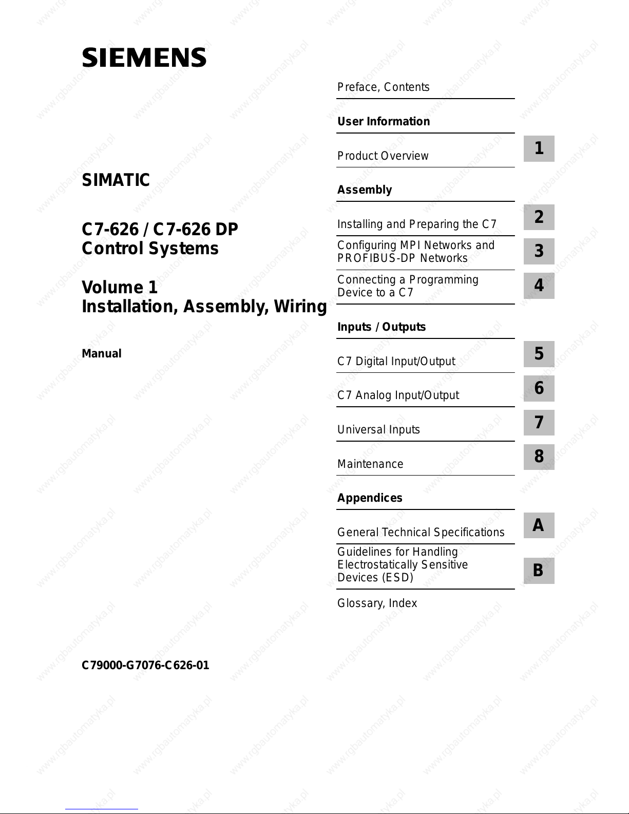
Preface, Contents
User Information
Product Overview
1
Assembly
Installing and Preparing the C7
2
Configuring MPI Networks and
PROFIBUS-DP Networks
3
Connecting a Programming
Device to a C7
4
Inputs / Outputs
C7 Digital Input/Output
5
C7 Analog Input/Output
6
Universal Inputs
7
Maintenance
8
Appendices
General Technical Specifications
A
Guidelines for Handling
Electrostatically Sensitive
Devices (ESD)
B
Glossary, Index
C79000-G7076-C626-01
C7-626 / C7-626 DP
Control Systems
Volume 1
Installation, Assembly, Wiring
Manual
SIMATIC
Page 4
C7-626 / C7-626 DP Control Systems
This manual contains notices which you should observe to ensure your own personal safety, as well as to
protect the product and connected equipment. These notices are highlighted in the manual by a warning
triangle and are marked as follows according to the level of danger:
!
Danger
indicates that death, severe personal injury or substantial property damage will result if proper precautions are
not taken.
!
Warning
indicates that death, severe personal injury or substantial property damage can result if proper precautions are
not taken.
!
Caution
indicates that minor personal injury or property damage can result if proper precautions are not taken.
Note
draws your attention to particularly important information on the product, handling the product, or to a particular
part of the documentation.
The device/system may only be set up and operated in conjunction with this manual.
Only qualified personnel should be allowed to install and work on this equipment. Qualified persons are
defined as persons who are authorized to commission, to ground, and to tag circuits, equipment, and sys-
tems in accordance with established safety practices and standards.
Note the following:
!
Warning
This device and its components may only be used for the applications described in the catalog or the technical
description, and only in connection with devices or components from other manufacturers which have been
approved or recommended by Siemens.
This product can only function correctly and safely if it is transported, stored, set up, and installed correctly, and
operated and maintained as recommended.
SIMATICR and SINECR are registered trademarks of SIEMENS AG.
Third parties using for their own purposes any other names in this document which refer to
trademarks might infringe upon the rights of the trademark owners.
We have checked the contents of this manual for agreement with the
hardware and software described. Since deviations cannot be precluded
entirely, we cannot guarantee full agreement. However, the data in this
manual are reviewed regularly and any necessary corrections included in
subsequent editions. Suggestions for improvement are welcomed.
E Siemens AG 1996
T echnical data subject to change.
Disclaimer of LiabilityCopyright E Siemens AG 1996 All rights reserved
The reproduction, transmission or use of this document or its contents is
not permitted without express written authority. Of fenders will be liable for
damages. All rights, including rights created by patent grant or registration
of a utility model or design, are reserved.
Siemens AG
Automation Group
Industrial Automation Systems
Postfach 4848, D-90327 Nürnberg
Siemens Aktiengesellschaft
Order No. C79000-G7076-C626
Safety Guidelines
Qualified Personnel
Correct Usage
Trademarks
Page 5
iii
C7-626 / C7-626 DP Control Systems
C79000-G7076-C626-01
Preface
The information in this manual will enable you to do the following:
S Install and wire a C7-626 or C7-626 DP (Volume 1).
S Assign parameters to the CPU of the C7-626 or C7-626 DP, load a user
program into this CPU and run the program (Volume 2).
S Put the C7-626 and C7-626 DP into operation and use the operator
interface (O/I) functions (Volume 2).
The manual is divided to take into account two different types of reader:
S Volume 1:
Users who carry out the mechanical and electrical installation of the C7 at
the location of use and who bring the C7 to a state of readiness for
immediate use.
S Volume 2:
Users who create control programs and O/I configurations, load them into
the C7, and print out screen displays and messages.
This manual describes the hardware and software of the C7-626 and C7-626
DP. It consists of two volumes.
Volume 1 of the manual covers the following topics:
S Installation and preparation of the C7-626 or C7-626 DP
S Networking the C7-626 or C7-626 DP with programming devices (PGs)
and other devices
S Connecting the digital and analog I/Os
S Connecting the I/Os to the universal inputs
S Connecting the IM361 interface module
S Connecting a printer to the C7
Purpose
Audience
Contents of This
Manual
Page 6
iv
C7-626 / C7-626 DP Control Systems
C79000-G7076-C626-01
Volume 2 of the manual covers the following topics:
S Starting up the C7
S Controlling with the C7 CPU
S Addressing and assigning parameters to the C7 I/O
S C7 diagnostics
S Using the O/I functions of the C7
To make the manual easier to read, the device type description C7-626 or
C7-626 DP will be referred to throughout the manual as C7.
This manual is valid for the following C7s:
C7 Order Number
C7-626 6ES7626-1AG00-0AE3
C7-626 DP 6ES7626-2AG00-0AE3
This manual is available under order number 6ES7626-1AE00-8BA0.
This manual describes the C7-626 and C7-626 DP. For programming,
expanding and configuring a C7, you also require the following manuals:
Conventions
Concerning C7
Scope of This
Manual
C7 Manual
Other Pertinent
Manuals
Preface
Page 7

v
C7-626 / C7-626 DP Control Systems
C79000-G7076-C626-01
C7
Programming
Assigning parameters
ConfiguringExpanding
ProTool
Hardware and Installation
If required
Statement List for
S7-300 and S7-400
Ladder Logic for
S7-300 and S7-400
System and Standard
Functions
STEP 7 User Manual
Program Design
Module Specifications
Preface
Page 8
vi
C7-626 / C7-626 DP Control Systems
C79000-G7076-C626-01
Table 1-1 STEP 7 Documentation Package
Manual Contents
Standard Software for S7
and M7
STEP 7 User Manual
Provides information on working with the STEP 7 tools
S Installing and starting up STEP 7 on a programming device/PC
S Handling tools with the following contents:
– Managing projects and files
– Configuring and assigning parameters to the S7-300
– Assigning symbolic names for the user program
– Creating and testing the user program in STL/LAD
– Creating data blocks
– Configuring communications between several CPUs
– Loading, storing and deleting the user program in the programming
device/CPU
– Monitoring and controlling the user program (for example, variables)
– Monitoring and controlling the CPU (for example, operating mode, memory
reset, memory compression, protection levels)
Statement List for
S7-300/S7-400
Programming Manual
or
Ladder Logic for
S7-300/S7-400
Programming Manual
Reference manual for programming with STL or LAD:
S Basics for working with STL/LAD (for example, structure of STL/LAD, number
formats, syntax)
S Description of all operations in STEP 7 (with programming examples)
S Description of the different addressing possibilities in STEP 7 (with examples)
S Description of all integral functions of the CPUs
S Description of the CPU-internal registers
System Software for
S7-300/S7-400 System and
Standard Functions
Reference Manual
Detailed description of
S all standard functions (FCs) integrated into STEP 7
S all system functions (SFCs) integrated into the operating system of a CPU
Standard Software for S7
Converting S5 Programs
Manual
Provides information on converting STEP 5 programs to STEP 7:
S Working with the S5/S7 Converter
S Rules for conversion
S Using converted STEP 5 standard function blocks in STEP 7
Master Index S Master index for all the manuals in the documentation package.
Preface
Page 9
vii
C7-626 / C7-626 DP Control Systems
C79000-G7076-C626-01
You will find a list of further information sources on the subject of the
S7-300 and other programmable controllers in Appendix D of Volume 2 of
this manual.
Table 1-2 Additional Manuals
Manual Contents
System Software for S7-300
and S7-400 Program Design
Programming Manual
Provides basic information on designing STEP 7 programs:
S Instructions for the efficient solution of programming tasks with the
programming device/PC and STEP 7
S How the CPUs operate (for example, memory concept, I/O access, addressing,
blocks, data types, data management)
S Description of STEP 7 data management
S Using STEP 7 data types
S Using linear and structured programming (with programming examples)
S Using block call operations
S Overview of how to use the STEP 7 applications for developing projects (with
detailed examples)
S Using the test and diagnostic functions of the CPUs in the user program (for
example, error OBs, status word)
S7-300 Programmable
Controller
Installation and Hardware
Describes the hardware of the S7-300:
S Electrical configuration of the S7-300
S Installing the S7-300
S Wiring and preparing the S7-300 for operation
S Characteristics and technical specifications of the S7-300 modules
S7-300/M7-300
Programmable Controllers
Module Specifications
Reference Manual
Describes the hardware of the S7-300 modules:
S Analog modules
S Digital modules
S Interface modules
S Characteristics and technical specifications of the S7-300 modules
S7-300 Programmable
Controller CPU 312 / CPU
314/ CPU 315 / CPU 315
DP, Instruction List
Describes the instruction set of the CPU 312, CPU 314, CPU 315 and CPU 315 DP,
including the execution times of all operations.
PG 7xx Describes the programming device (PG) hardware:
S Assembling and starting up the programming device
S Expansion possibilities
S Configuring
S Error diagnostics
COROS
ProTool
Manual for creating configurations:
S Using ProTool
S Configuring
S Displays and messages
S Loading the configuration into the C7
Other References
Preface
Page 10
viii
C7-626 / C7-626 DP Control Systems
C79000-G7076-C626-01
This manual has the following aids to help you find specific information:
S At the beginning of the two volumes, you will find a complete directory
of contents.
S In each chapter, you will find information in the left-hand column of
every page giving you an overview of the contents of that section.
S After the Appendices, there is a Glossary containing important technical
terms used in the manual.
S At the end of the manual, there is a detailed index.
The C7 control system conforms to standards as described in Appendix A.1.
If you have any questions concerning the C7 control system, please contact
your local Siemens representative.
You will find a list of Siemens representatives worldwide in Volume 2 of the
manual, Appendix E.
If you have any questions or remarks concerning the manual, please fill in
and return the Suggestions/Corrections form at the back of Volume 2.
Structure of This
Manual
Standards
Queries
Preface
Page 11
ix
C7-626 / C7-626 DP Control Systems
C79000-G7076-C626-01
Contents
1 Product Overview 1-1. . . . . . . . . . . . . . . . . . . . . . . . . . . . . . . . . . . . . . . . . . . . . . . . . . . . . . .
2 Installing and Preparing the C7 2-1. . . . . . . . . . . . . . . . . . . . . . . . . . . . . . . . . . . . . . . . . . .
2.1 Scope of Supply and C7 Accessories 2-2. . . . . . . . . . . . . . . . . . . . . . . . . . . . . . .
2.2 Inserting the Labeling Strips 2-4. . . . . . . . . . . . . . . . . . . . . . . . . . . . . . . . . . . . . . .
2.3 Installing a C7 2-6. . . . . . . . . . . . . . . . . . . . . . . . . . . . . . . . . . . . . . . . . . . . . . . . . . .
2.4 Arranging the C7 in the Mechanical Environment 2-9. . . . . . . . . . . . . . . . . . . . .
2.5 Electrical Installation and Connector Pin Assignment 2-10. . . . . . . . . . . . . . . . .
2.6 Setup Guidelines for Interference-Proof Installation 2-16. . . . . . . . . . . . . . . . . . .
2.7 Connecting Shielded Cables 2-18. . . . . . . . . . . . . . . . . . . . . . . . . . . . . . . . . . . . . . .
2.8 Keying Connectors 2-19. . . . . . . . . . . . . . . . . . . . . . . . . . . . . . . . . . . . . . . . . . . . . . .
2.9 Arrangement of Additional S7-300 Modules 2-20. . . . . . . . . . . . . . . . . . . . . . . . .
2.10 C7 Clocks 2-22. . . . . . . . . . . . . . . . . . . . . . . . . . . . . . . . . . . . . . . . . . . . . . . . . . . . . . .
2.11 Starting Up 2-24. . . . . . . . . . . . . . . . . . . . . . . . . . . . . . . . . . . . . . . . . . . . . . . . . . . . . .
2.11.1 With a Loaded Configuration in the C7 OP 2-25. . . . . . . . . . . . . . . . . . . . . . . . . .
2.11.2 Without a Loaded Configuration in the C7 OP 2-26. . . . . . . . . . . . . . . . . . . . . . . .
2.12 Status and Error LEDs on the C7 2-27. . . . . . . . . . . . . . . . . . . . . . . . . . . . . . . . . . .
3 Configuring MPI Networks and PROFIBUS-DP Networks 3-1. . . . . . . . . . . . . . . . . . .
3.1 Setting Up a Network 3-2. . . . . . . . . . . . . . . . . . . . . . . . . . . . . . . . . . . . . . . . . . . . .
3.2 Rules for Configuring a Network 3-5. . . . . . . . . . . . . . . . . . . . . . . . . . . . . . . . . . .
3.3 Cable Lengths 3-12. . . . . . . . . . . . . . . . . . . . . . . . . . . . . . . . . . . . . . . . . . . . . . . . . . .
3.4 Network Components 3-15. . . . . . . . . . . . . . . . . . . . . . . . . . . . . . . . . . . . . . . . . . . . .
3.5 Bus Connectors 3-17. . . . . . . . . . . . . . . . . . . . . . . . . . . . . . . . . . . . . . . . . . . . . . . . . .
3.5.1 PROFIBUS Bus Connector 3-18. . . . . . . . . . . . . . . . . . . . . . . . . . . . . . . . . . . . . . . .
3.5.2 Bus Connector 6ES7 972-0B.20-0XA0 3-19. . . . . . . . . . . . . . . . . . . . . . . . . . . . . .
3.5.3 Bus Connector 6ES7 972-0B.10-0XA0 3-22. . . . . . . . . . . . . . . . . . . . . . . . . . . . . .
3.5.4 Plugging the Bus Connector into the Module 3-24. . . . . . . . . . . . . . . . . . . . . . . . .
3.6 Starting Up the PROFIBUS DP 3-25. . . . . . . . . . . . . . . . . . . . . . . . . . . . . . . . . . . .
4 Connecting a Programming Device/PC to a C7 4-1. . . . . . . . . . . . . . . . . . . . . . . . . . . .
4.1 Connecting a Programming Device/PC to a C7 4-2. . . . . . . . . . . . . . . . . . . . . .
4.2 Connecting a Programming Device/PC to Several Nodes 4-3. . . . . . . . . . . . .
Page 12
x
C7-626 / C7-626 DP Control Systems
C79000-G7076-C626-01
5 C7 Digital Input/Output 5-1. . . . . . . . . . . . . . . . . . . . . . . . . . . . . . . . . . . . . . . . . . . . . . . . . .
5.1 Digital Input Function 5-2. . . . . . . . . . . . . . . . . . . . . . . . . . . . . . . . . . . . . . . . . . . . .
5.2 Digital Output Function 5-4. . . . . . . . . . . . . . . . . . . . . . . . . . . . . . . . . . . . . . . . . . .
5.3 Status Bits of the DI/DO 5-7. . . . . . . . . . . . . . . . . . . . . . . . . . . . . . . . . . . . . . . . . . .
6 C7 Analog Input/Output 6-1. . . . . . . . . . . . . . . . . . . . . . . . . . . . . . . . . . . . . . . . . . . . . . . . . .
6.1 Connecting Transducers to Analog Inputs 6-2. . . . . . . . . . . . . . . . . . . . . . . . . . .
6.1.1 Connecting Voltage and Current Transducers 6-5. . . . . . . . . . . . . . . . . . . . . . . .
6.2 Connecting Loads/Actuators to the Analog Output 6-6. . . . . . . . . . . . . . . . . . . .
6.3 Analog Input Function 6-9. . . . . . . . . . . . . . . . . . . . . . . . . . . . . . . . . . . . . . . . . . . .
6.3.1 Characteristics and Technical Specifications of the Analog Input Module 6-10
6.4 Analog Output Function 6-15. . . . . . . . . . . . . . . . . . . . . . . . . . . . . . . . . . . . . . . . . . .
7 Universal Inputs 7-1. . . . . . . . . . . . . . . . . . . . . . . . . . . . . . . . . . . . . . . . . . . . . . . . . . . . . . . . .
8 Maintenance 8-1. . . . . . . . . . . . . . . . . . . . . . . . . . . . . . . . . . . . . . . . . . . . . . . . . . . . . . . . . . . .
8.1 Changing and Disposing of the Back-Up Battery 8-2. . . . . . . . . . . . . . . . . . . . .
8.2 Replacing the C7 8-6. . . . . . . . . . . . . . . . . . . . . . . . . . . . . . . . . . . . . . . . . . . . . . . .
A General Technical Specifications A-1. . . . . . . . . . . . . . . . . . . . . . . . . . . . . . . . . . . . . . . . .
A.1 Technical Specifications A-2. . . . . . . . . . . . . . . . . . . . . . . . . . . . . . . . . . . . . . . . . . .
A.2 Notes on the CE Marking A-5. . . . . . . . . . . . . . . . . . . . . . . . . . . . . . . . . . . . . . . . .
A.3 Notes for the Machine Manufacturer A-6. . . . . . . . . . . . . . . . . . . . . . . . . . . . . . . .
A.4 Transport and Storage Conditions for Back-Up Batteries A-7. . . . . . . . . . . . . .
B Guidelines for Handling Electrostatically Sensitive Devices (ESD) B-1. . . . . . . . . .
B.1 What is ESD? B-2. . . . . . . . . . . . . . . . . . . . . . . . . . . . . . . . . . . . . . . . . . . . . . . . . . .
B.2 Electrostatic Charging of Objects and Persons B-3. . . . . . . . . . . . . . . . . . . . . . .
B.3 General Protective Measures Against Electrostatic Discharge Damage B-4.
B.4 Taking Measurements and Working on ESD Modules B-6. . . . . . . . . . . . . . . . .
B.5 Packing Electrostatically Sensitive Devices B-6. . . . . . . . . . . . . . . . . . . . . . . . . .
Glossary Glossary-1. . . . . . . . . . . . . . . . . . . . . . . . . . . . . . . . . . . . . . . . . . . . . . . . . . . . . . . . . .
Index Index-1. . . . . . . . . . . . . . . . . . . . . . . . . . . . . . . . . . . . . . . . . . . . . . . . . . . . . . . . . . . . .
Contents
Page 13
1-1
C7-626 / C7-626 DP Control Systems
C79000-G7076-C626-01
Product Overview
This chapter contains general information concerning the C7-626 and
C7-626 DP. A brief overview of the performance range provides you with a
first impression of the two units.
This chapter also tells you which additional components you can connect to a
C7 device.
To operate the C7, you require the following accessories:
S Programming device (PG) or PC with a multipoint interface and
programming device cable.
S You must load the following on to the programming device or PC
– the STEP 7 applications
– ProTool.
Overview
Accessories for
Operating the C7
1
Page 14
1
1-2
C7-626 / C7-626 DP Control Systems
C79000-G7076-C626-01
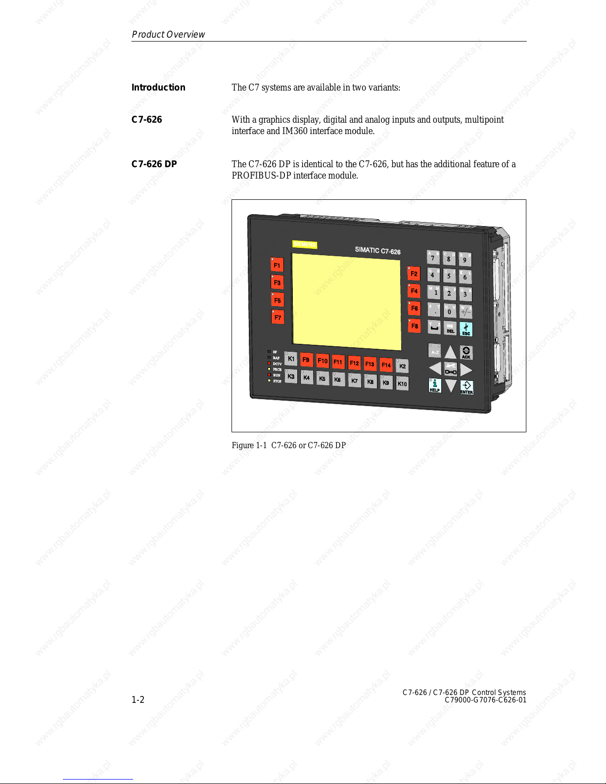
The C7 systems are available in two variants:
With a graphics display, digital and analog inputs and outputs, multipoint
interface and IM360 interface module.
The C7-626 DP is identical to the C7-626, but has the additional feature of a
PROFIBUS-DP interface module.
Figure 1-1 C7-626 or C7-626 DP
Introduction
C7-626
C7-626 DP
Product Overview
Page 15

1
1-3
C7-626 / C7-626 DP Control Systems
C79000-G7076-C626-01
With the C7 devices you can:
S Load and run user programs on the C7 CPU.
S Connect the C7-626 DP to the PROFIBUS DP via an integrated DP
interface.
S Process digital and analog signals using the integrated I/Os of the C7.
S Use interrupt inputs and counters (for frequency measurement, period
duration measurement, etc.).
S Load and use O/I applications that you have created using the “ProTool”
configuring tool.
S Use these configurations to monitor and intervene in the process you are
controlling with the user program.
S Output data to a printer.
The C7 has two units that work independently of each other and can
communicate with each other via the internally-looped C7 multipoint
interface (MPI).
S C7 CPU
S C7 OP
These components will be referred to explicitly in the manuals as required.
In addition to the connections to the process, you can also connect different
components to the C7. The most important components and their functions
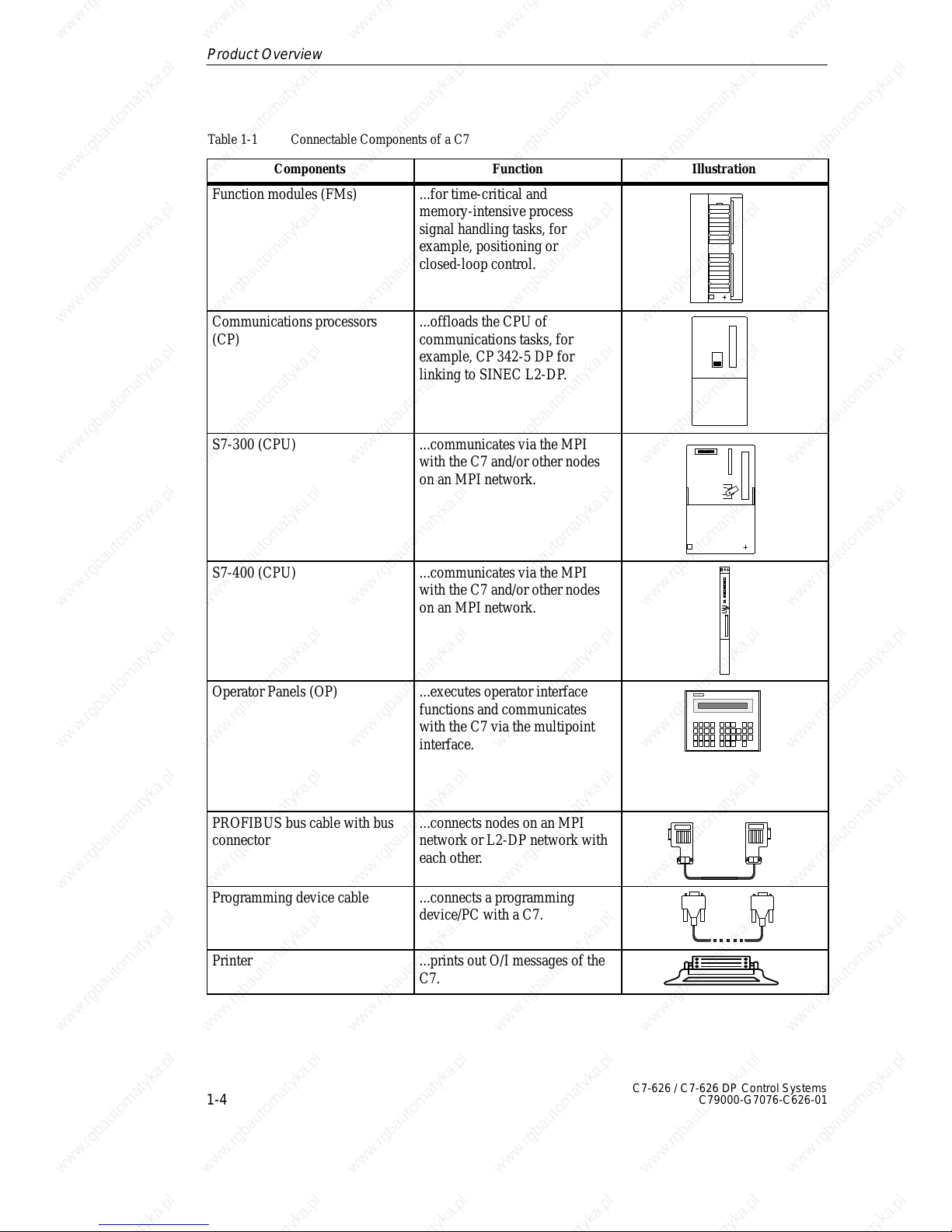
are listed in Table 1-1:
Table 1-1 Connectable Components of a C7
Components
Function Illustration
Interface module (IM361) ...connects a C7 with an
expansion rack for S7-300
modules
Signal modules (SMs)
(digital input modules,
digital output modules,
analog input modules,
analog output modules,
analog input/output modules)
...pass different process signal
levels on to the C7 CPU. They
can be connected to the C7 via
an IM361.
Performance
Range
C7 Units
Connectable
Components
of a C7
Product Overview
Page 16
1
1-4
C7-626 / C7-626 DP Control Systems
C79000-G7076-C626-01
Table 1-1 Connectable Components of a C7
Components IllustrationFunction
Function modules (FMs) ...for time-critical and
memory-intensive process
signal handling tasks, for
example, positioning or
closed-loop control.
Communications processors
(CP)
...offloads the CPU of
communications tasks, for
example, CP 342-5 DP for
linking to SINEC L2-DP.
S7-300 (CPU) ...communicates via the MPI
with the C7 and/or other nodes
on an MPI network.
S7-400 (CPU) ...communicates via the MPI
with the C7 and/or other nodes
on an MPI network.
Operator Panels (OP) ...executes operator interface
functions and communicates
with the C7 via the multipoint
interface.
PROFIBUS bus cable with bus
connector
...connects nodes on an MPI
network or L2-DP network with
each other.
Programming device cable ...connects a programming
device/PC with a C7.
Printer ...prints out O/I messages of the
C7.
Product Overview
Page 17
1
1-5
C7-626 / C7-626 DP Control Systems
C79000-G7076-C626-01
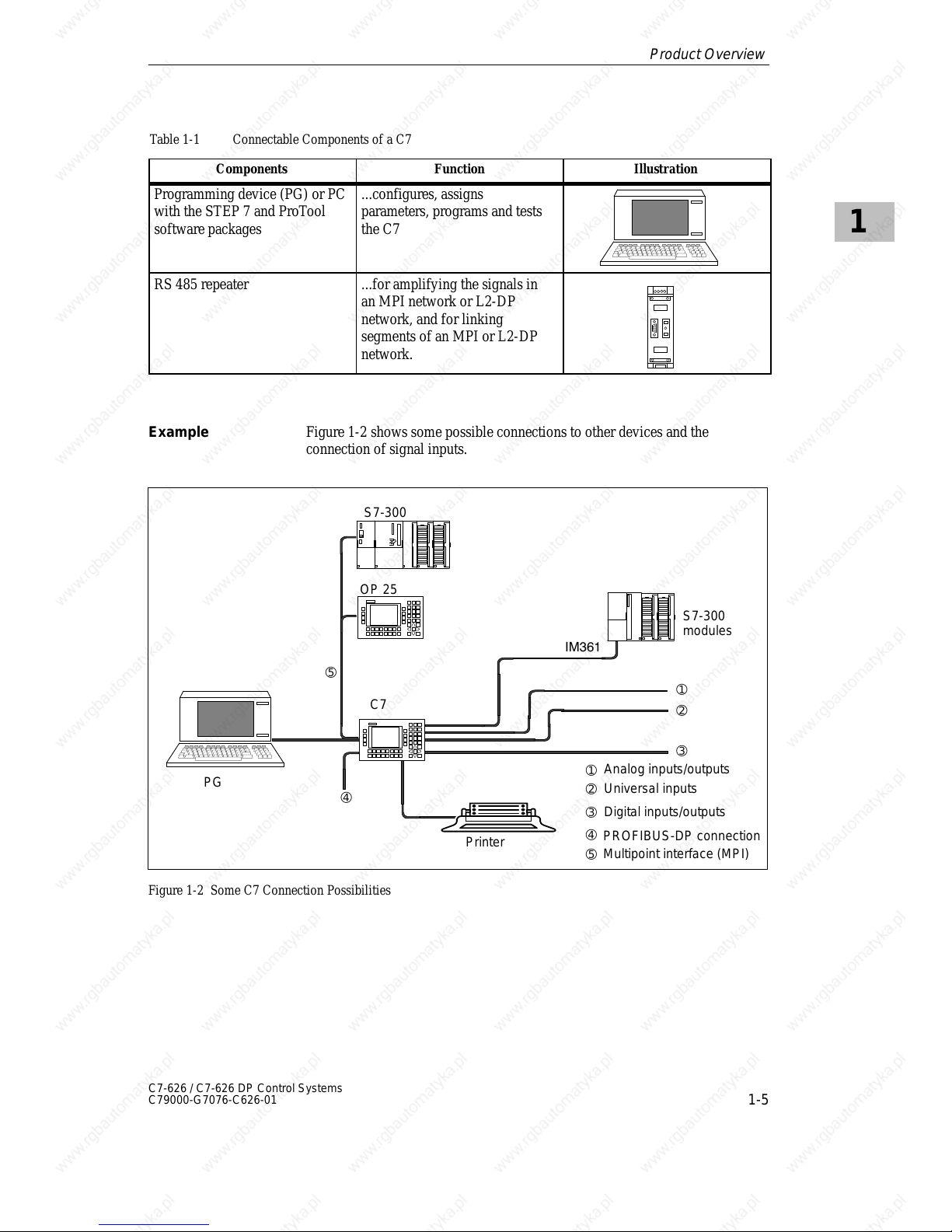
Table 1-1 Connectable Components of a C7
Components IllustrationFunction
Programming device (PG) or PC
with the STEP 7 and ProTool
software packages
...configures, assigns
parameters, programs and tests
the C7
RS 485 repeater ...for amplifying the signals in
an MPI network or L2-DP
network, and for linking
segments of an MPI or L2-DP
network.
Figure 1-2 shows some possible connections to other devices and the
connection of signal inputs.
IM361
C7
S7-300
modules
S7-300
PG
Printer
Digital inputs/outputs
Universal inputs
Analog inputs/outputs
OP 25
➀
➂
➁
➃
➄
➀
➁
➂
➃
➄
PROFIBUS-DP connection
Multipoint interface (MPI)
Figure 1-2 Some C7 Connection Possibilities
Example
Product Overview
Page 18

1
1-6
C7-626 / C7-626 DP Control Systems
C79000-G7076-C626-01
Product Overview
Page 19
2-1
C7-626 / C7-626 DP Control Systems
C79000-G7076-C626-01
Installing and Preparing the C7
In Section You Will Find On Page
2.1 Scope of Supply and C7 Accessories 2-2
2.2 Inserting the Labeling Strips 2-4
2.3 Installing a C7 2-6
2.4 Arranging the C7 in the Mechanical
Environment
2-9
2.5 Electrical Installation and Connector Pin
Assignment
2-10
2.6 Setup Guidelines for Interference-Proof
Installation
2-16
2.7 Connecting Shielded Cables 2-18
2.8 Keying Connectors 2-19
2.9 Arrangement of Additional S7-300 Modules 2-20
2.10 C7 Clocks 2-22
2.11 Starting Up 2-24
2.11.1 With a Loaded configuration in the C7 OP 2-25
2.11.2 Without a Loaded Configuration in the C7 OP 2-26
2.12 Status and Error LEDs on the C7 2-28
Summary of
Sections
2
Page 20
2
2-2
C7-626 / C7-626 DP Control Systems
C79000-G7076-C626-01
2.1 Scope of Supply and C7 Accessories
The following components are included in the scope of supply of the C7-626
or C7-626 DP:
S C7-626 or C7-626 DP
S A set of labeling strips (for function keys and softkeys)
S Battery
S A grounding bar
S 6 shielding clips
S 1 seal and 4 brackets
S Product Information
The following components can be ordered as spare parts for the C7:
S Labeling strips for function keys and softkeys 6ES7 623-1AE00-1AA0
S Service package (seal and 4 brackets) 6ES7 623-1AE00-3AA0
S Back-up battery 6ES7 623-1AE00-5AA0
The following components can be ordered as C7-specific accessories:
S C7-626/C7-626 DP Control Systems manual comprising two volumes in
the languages:
German: 6ES7 626-1AE00-8AA0
English: 6ES7 626-1AE00-8BA0
French: 6ES7 626-1AE00-8CA0
Spanish: 6ES7 626-1AE00-8DA0
Italian: 6ES7 626-1AE00-8EA0
S Plug connectors for C7 I/O with coding keys and coding sliders
6ES7 623-1AE00-4AA0.
The following components can be ordered as important standard accessories
for the C7:
S Programming device cable 6ES7 901-0BF00-0AA0 (for connecting the
C7 to the programming device)
S PC/MPI cable, 5 m 6ES7 901-2BF00-0AA0
S IM cable (for connecting additional modules)
IM cable, 1 m 6ES7 368-3BB00-0AA0
IM cable, 2.5 m 6ES7 368-3BC51-0AA0
IM cable, 5 m 6ES7 368-3BF00-0AA0
IM cable, 10 m 6ES7 368-3CB00-0AA0
Parts Supplied
Spare Parts
Accessories
Installing and Preparing the C7
Page 21
2
2-3
C7-626 / C7-626 DP Control Systems
C79000-G7076-C626-01
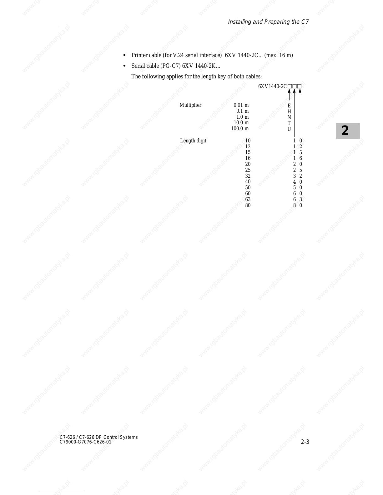
S Printer cable (for V.24 serial interface) 6XV 1440-2C... (max. 16 m)
S Serial cable (PG-C7) 6XV 1440-2K...
The following applies for the length key of both cables:
6XV1440-2Cjjj
Multiplier 0.01 m
0.1 m
1.0 m
10.0 m
100.0 m
E
H
N
T
U
1
1
1
1
2
2
3
4
5
6
6
8
Length digit 10
12
15
16
20
25
32
40
50
60
63
80
0
2
5
6
0
5
2
0
0
0
3
0
Installing and Preparing the C7
Page 22
2
2-4
C7-626 / C7-626 DP Control Systems
C79000-G7076-C626-01
2.2 Inserting the Labeling Strips
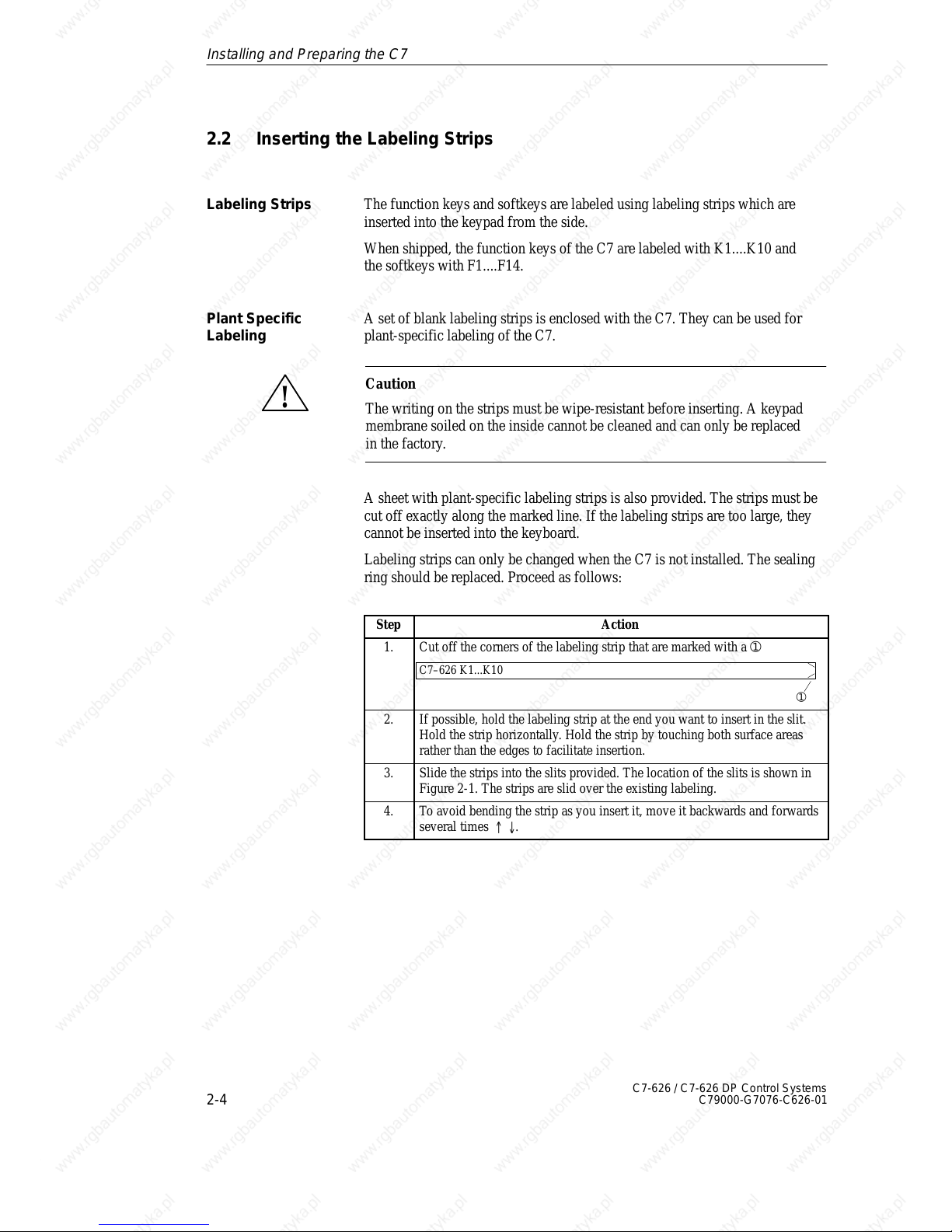
The function keys and softkeys are labeled using labeling strips which are
inserted into the keypad from the side.
When shipped, the function keys of the C7 are labeled with K1....K10 and
the softkeys with F1....F14.
A set of blank labeling strips is enclosed with the C7. They can be used for
plant-specific labeling of the C7.
!
Caution
The writing on the strips must be wipe-resistant before inserting. A keypad
membrane soiled on the inside cannot be cleaned and can only be replaced
in the factory.
A sheet with plant-specific labeling strips is also provided. The strips must be
cut off exactly along the marked line. If the labeling strips are too large, they
cannot be inserted into the keyboard.
Labeling strips can only be changed when the C7 is not installed. The sealing
ring should be replaced. Proceed as follows:
Step Action
1. Cut off the corners of the labeling strip that are marked with a ➀
C7–626 K1...K10
➀
2. If possible, hold the labeling strip at the end you want to insert in the slit.
Hold the strip horizontally. Hold the strip by touching both surface areas
rather than the edges to facilitate insertion.
3. Slide the strips into the slits provided. The location of the slits is shown in
Figure 2-1. The strips are slid over the existing labeling.
4. To avoid bending the strip as you insert it, move it backwards and forwards
several times .
Labeling Strips
Plant Specific
Labeling
Installing and Preparing the C7
Page 23

2
2-5
C7-626 / C7-626 DP Control Systems
C79000-G7076-C626-01
Labeling Strips
Labeling Strips
Figure 2-1 Inserting Labeling Strips
Installing and Preparing the C7
Page 24
2
2-6
C7-626 / C7-626 DP Control Systems
C79000-G7076-C626-01
2.3 Installing a C7
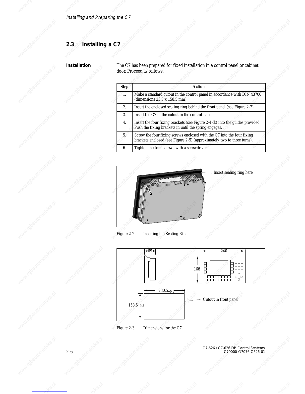
The C7 has been prepared for fixed installation in a control panel or cabinet
door. Proceed as follows:
Step Action
1. Make a standard cutout in the control panel in accordance with DIN 43700
(dimensions 23.5 x 158.5 mm).
2. Insert the enclosed sealing ring behind the front panel (see Figure 2-2).
3. Insert the C7 in the cutout in the control panel.
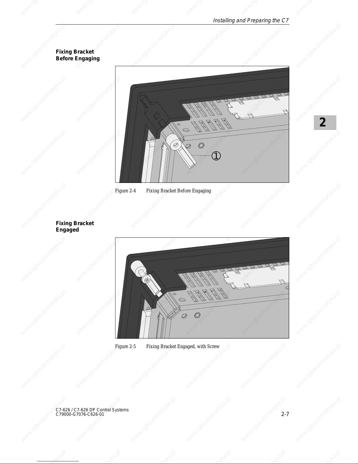
4. Insert the four fixing brackets (see Figure 2-4 ➀) into the guides provided.
Push the fixing brackets in until the spring engages.
5. Screw the four fixing screws enclosed with the C7 into the four fixing
brackets enclosed (see Figure 2-5) (approximately two to three turns).
6. Tighten the four screws with a screwdriver.
Insert sealing ring here
Figure 2-2 Inserting the Sealing Ring
168
24069
230.5
+0.5
158.5
+0.5
Cutout in front panel
Figure 2-3 Dimensions for the C7
Installation
Installing and Preparing the C7
Page 25
2
2-7
C7-626 / C7-626 DP Control Systems
C79000-G7076-C626-01
➀
Figure 2-4 Fixing Bracket Before Engaging
Figure 2-5 Fixing Bracket Engaged, with Screw
Fixing Bracket
Before Engaging
Fixing Bracket
Engaged
Installing and Preparing the C7
Page 26
2
2-8
C7-626 / C7-626 DP Control Systems
C79000-G7076-C626-01
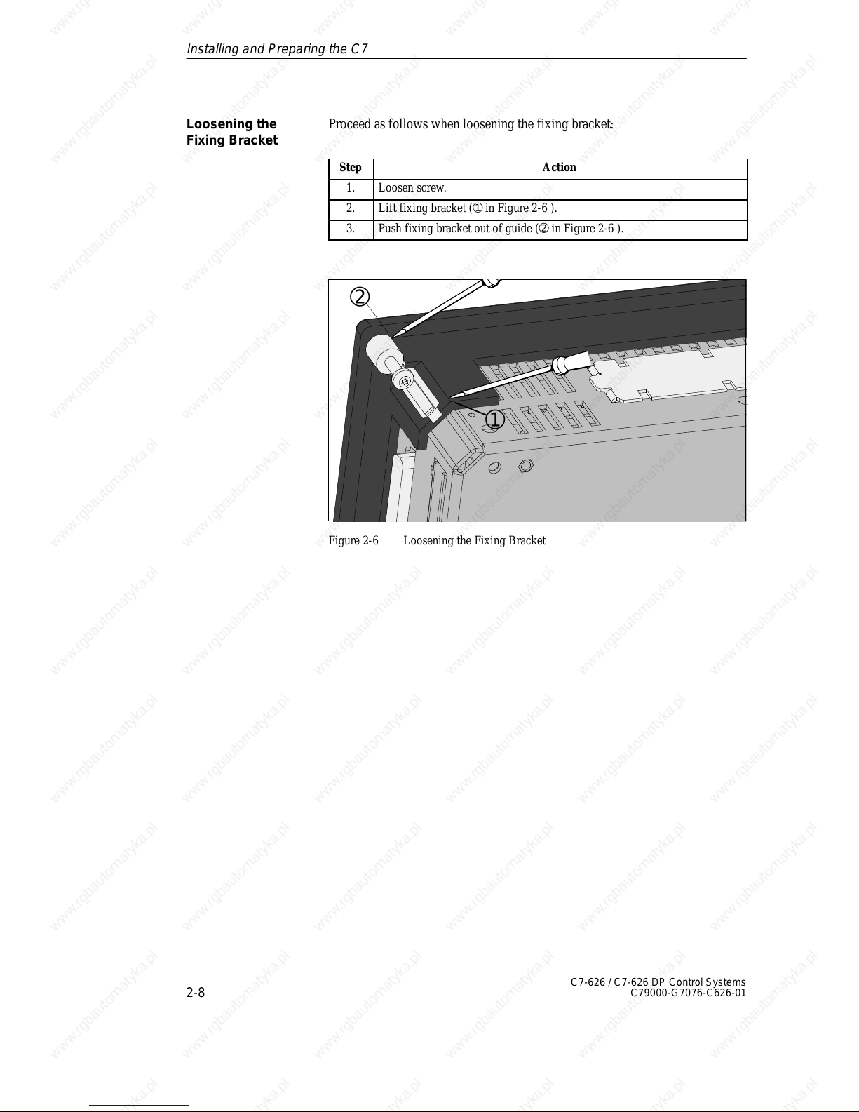
Proceed as follows when loosening the fixing bracket:
Step Action
1. Loosen screw.
2. Lift fixing bracket (➀ in Figure 2-6 ).
3. Push fixing bracket out of guide (➁ in Figure 2-6 ).
➁
➀
Figure 2-6 Loosening the Fixing Bracket
Loosening the
Fixing Bracket
Installing and Preparing the C7
Page 27
2
2-9
C7-626 / C7-626 DP Control Systems
C79000-G7076-C626-01
2.4 Arranging the C7 in the Mechanical Environment
When installing a C7, please note the following:
S The control panel may be 1 to 4 mm thick. Make sure the sealing ring fits
tightly in all places.
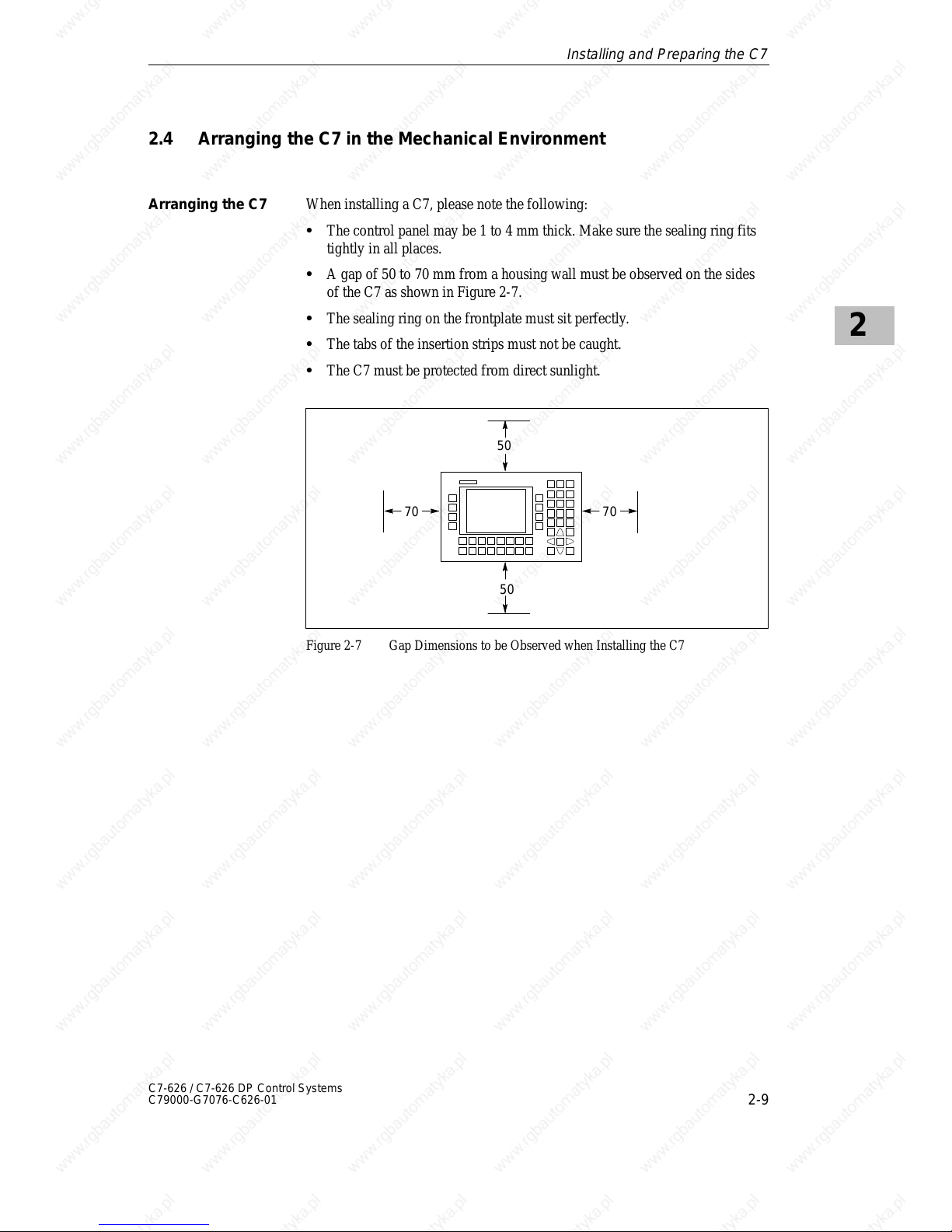
S A gap of 50 to 70 mm from a housing wall must be observed on the sides
of the C7 as shown in Figure 2-7.
S The sealing ring on the frontplate must sit perfectly.
S The tabs of the insertion strips must not be caught.
S The C7 must be protected from direct sunlight.
50
50
70 70
Figure 2-7 Gap Dimensions to be Observed when Installing the C7
Arranging the C7
Installing and Preparing the C7
Page 28
2
2-10
C7-626 / C7-626 DP Control Systems
C79000-G7076-C626-01
2.5 Electrical Installation and Connector Pin Assignment
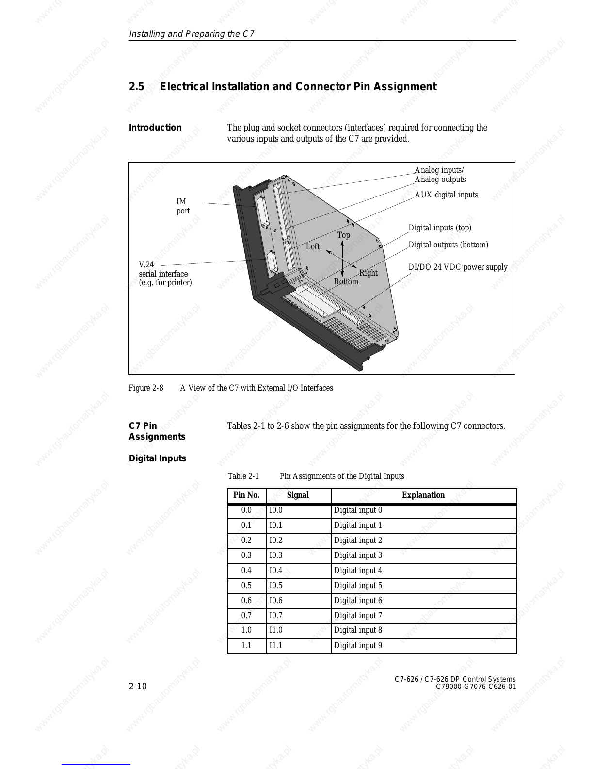
The plug and socket connectors (interfaces) required for connecting the
various inputs and outputs of the C7 are provided.
AUX digital inputs
IM
port
V.24
serial interface
(e.g. for printer)
Analog inputs/
Analog outputs
Digital inputs (top)
DI/DO 24 VDC power supply
Digital outputs (bottom)
Top
Bottom
Left
Right
Figure 2-8 A View of the C7 with External I/O Interfaces
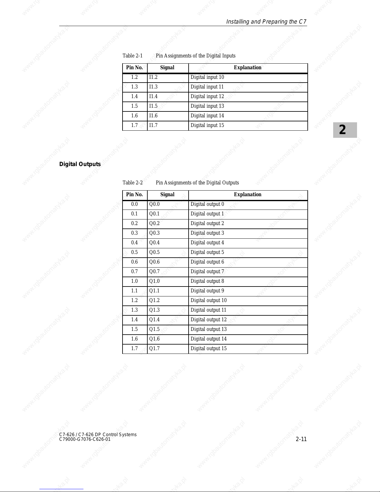
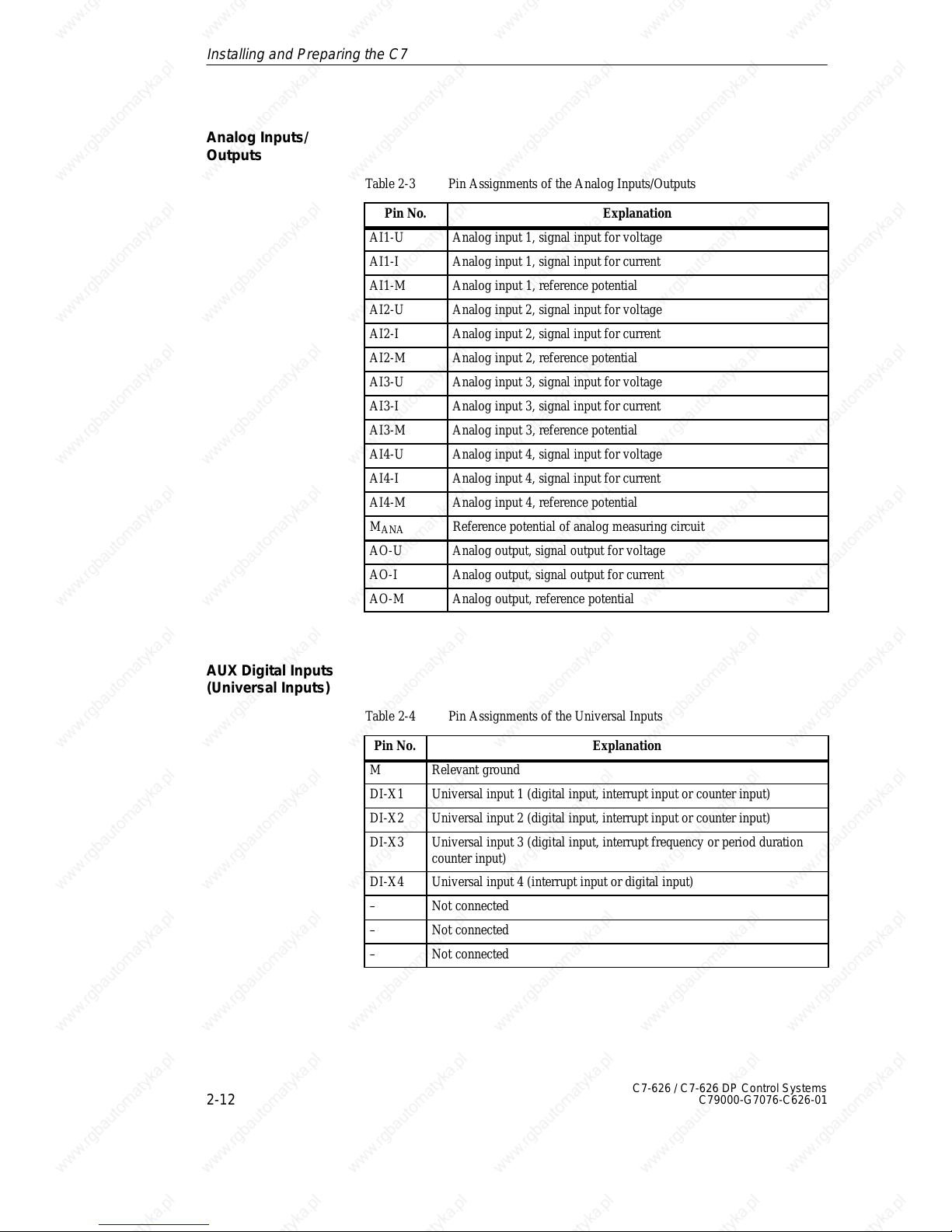
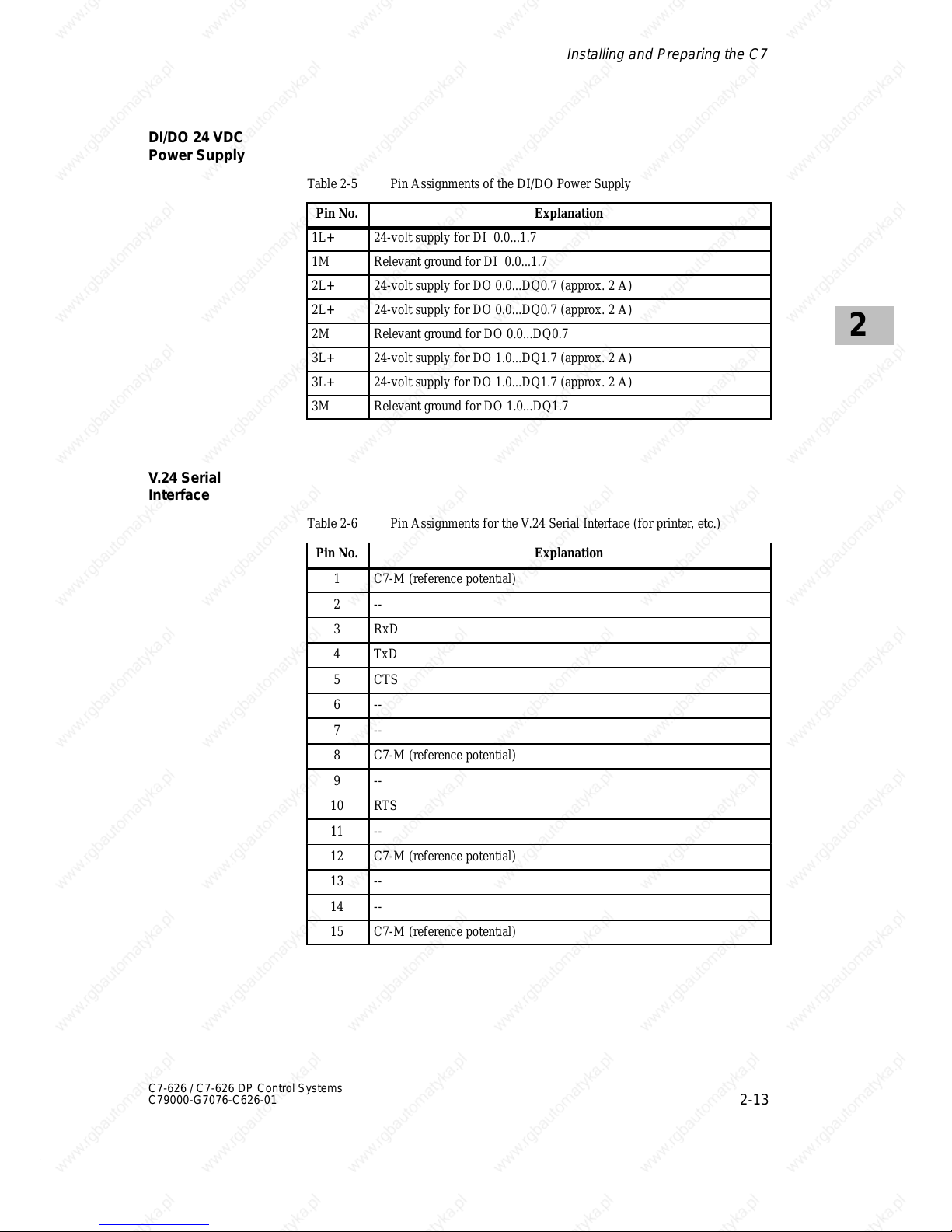
Tables 2-1 to 2-6 show the pin assignments for the following C7 connectors.
Table 2-1 Pin Assignments of the Digital Inputs
Pin No. Signal Explanation
0.0 I0.0 Digital input 0
0.1 I0.1 Digital input 1
0.2 I0.2 Digital input 2
0.3 I0.3 Digital input 3
0.4 I0.4 Digital input 4
0.5 I0.5 Digital input 5
0.6 I0.6 Digital input 6
0.7 I0.7 Digital input 7
1.0 I1.0 Digital input 8
1.1 I1.1 Digital input 9
Introduction
C7 Pin
Assignments
Digital Inputs
Installing and Preparing the C7
Page 29
2
2-11
C7-626 / C7-626 DP Control Systems
C79000-G7076-C626-01
Table 2-1 Pin Assignments of the Digital Inputs
Pin No. ExplanationSignal
1.2 I1.2 Digital input 10
1.3 I1.3 Digital input 11
1.4 I1.4 Digital input 12
1.5 I1.5 Digital input 13
1.6 I1.6 Digital input 14
1.7 I1.7 Digital input 15
Table 2-2 Pin Assignments of the Digital Outputs
Pin No.
Signal Explanation
0.0 Q0.0 Digital output 0
0.1 Q0.1 Digital output 1
0.2 Q0.2 Digital output 2
0.3 Q0.3 Digital output 3
0.4 Q0.4 Digital output 4
0.5 Q0.5 Digital output 5
0.6 Q0.6 Digital output 6
0.7 Q0.7 Digital output 7
1.0 Q1.0 Digital output 8
1.1 Q1.1 Digital output 9
1.2 Q1.2 Digital output 10
1.3 Q1.3 Digital output 11
1.4 Q1.4 Digital output 12
1.5 Q1.5 Digital output 13
1.6 Q1.6 Digital output 14
1.7 Q1.7 Digital output 15
Digital Outputs
Installing and Preparing the C7
Page 30
2
2-12
C7-626 / C7-626 DP Control Systems
C79000-G7076-C626-01
Table 2-3 Pin Assignments of the Analog Inputs/Outputs
Pin No. Explanation
AI1-U Analog input 1, signal input for voltage
AI1-I Analog input 1, signal input for current
AI1-M Analog input 1, reference potential
AI2-U Analog input 2, signal input for voltage
AI2-I Analog input 2, signal input for current
AI2-M Analog input 2, reference potential
AI3-U Analog input 3, signal input for voltage
AI3-I Analog input 3, signal input for current
AI3-M Analog input 3, reference potential
AI4-U Analog input 4, signal input for voltage
AI4-I Analog input 4, signal input for current
AI4-M Analog input 4, reference potential
M
ANA
Reference potential of analog measuring circuit
AO-U Analog output, signal output for voltage
AO-I Analog output, signal output for current
AO-M Analog output, reference potential
Table 2-4 Pin Assignments of the Universal Inputs
Pin No.
Explanation
M Relevant ground
DI-X1 Universal input 1 (digital input, interrupt input or counter input)
DI-X2 Universal input 2 (digital input, interrupt input or counter input)
DI-X3 Universal input 3 (digital input, interrupt frequency or period duration
counter input)
DI-X4 Universal input 4 (interrupt input or digital input)
– Not connected
– Not connected
– Not connected
Analog Inputs/
Outputs
AUX Digital Inputs
(Universal Inputs)
Installing and Preparing the C7
Page 31
2
2-13
C7-626 / C7-626 DP Control Systems
C79000-G7076-C626-01
Table 2-5 Pin Assignments of the DI/DO Power Supply
Pin No. Explanation
1L+ 24-volt supply for DI 0.0...1.7
1M Relevant ground for DI 0.0...1.7
2L+ 24-volt supply for DO 0.0...DQ0.7 (approx. 2 A)
2L+ 24-volt supply for DO 0.0...DQ0.7 (approx. 2 A)
2M Relevant ground for DO 0.0...DQ0.7
3L+ 24-volt supply for DO 1.0...DQ1.7 (approx. 2 A)
3L+ 24-volt supply for DO 1.0...DQ1.7 (approx. 2 A)
3M Relevant ground for DO 1.0...DQ1.7
Table 2-6 Pin Assignments for the V.24 Serial Interface (for printer, etc.)
Pin No.
Explanation
1 C7-M (reference potential)
2 --
3 RxD
4 TxD
5 CTS
6 --
7 --
8 C7-M (reference potential)
9 --
10 RTS
11 --
12 C7-M (reference potential)
13 --
14 --
15 C7-M (reference potential)
DI/DO 24 VDC
Power Supply
V.24 Serial
Interface
Installing and Preparing the C7
Page 32
2
2-14
C7-626 / C7-626 DP Control Systems
C79000-G7076-C626-01
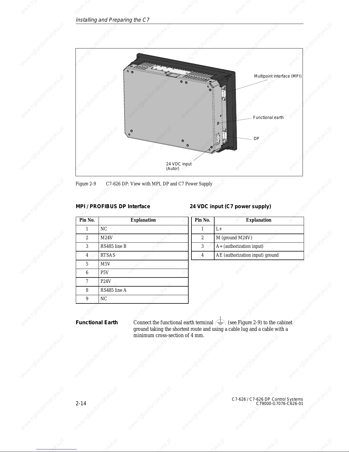
Multipoint interface (MPI)
24 VDC input
(Autor)
Functional earth
DP
Figure 2-9 C7-626 DP: View with MPI, DP and C7 Power Supply
MPI / PROFIBUS DP Interface 24 VDC input (C7 power supply)
Pin No. Explanation
1 NC
2 M24V
3 RS485 line B
4 RTSAS
5 M5V
6 P5V
7 P24V
8 RS485 line A
9 NC
Pin No. Explanation
1 L+
2 M (ground M24V)
3 A+ (authorization input)
4 AE (authorization input) ground
Connect the functional earth terminal (see Figure 2-9) to the cabinet
ground taking the shortest route and using a cable lug and a cable with a
minimum cross-section of 4 mm.
Functional Earth
Installing and Preparing the C7
Page 33
2
2-15
C7-626 / C7-626 DP Control Systems
C79000-G7076-C626-01
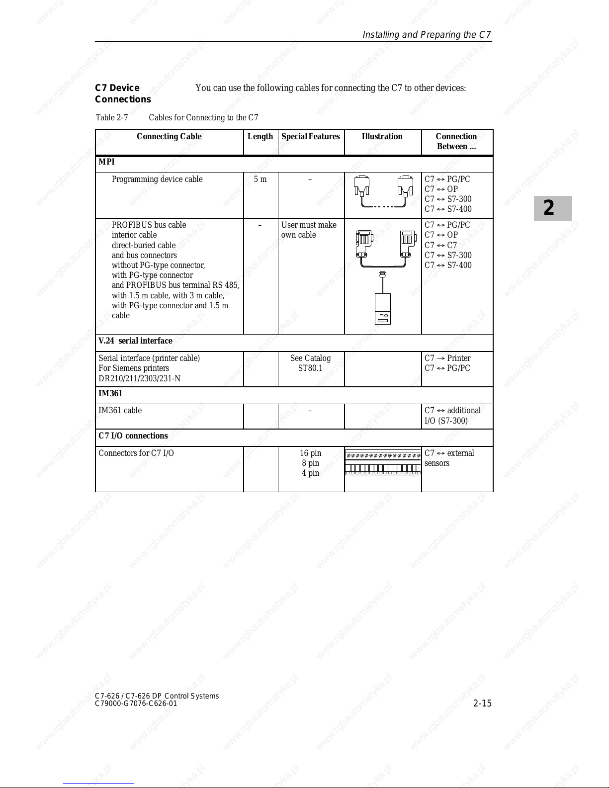
You can use the following cables for connecting the C7 to other devices:
Table 2-7 Cables for Connecting to the C7
Connecting Cable Length Special Featur es Illustration Connection
Between ...
MPI
Programming device cable 5 m – C7 ´ PG/PC
C7 ´ OP
C7 ´ S7-300
C7 ´ S7-400
PROFIBUS bus cable
interior cable
direct-buried cable
and bus connectors
without PG-type connector,
with PG-type connector
and PROFIBUS bus terminal RS 485,
with 1.5 m cable, with 3 m cable,
with PG-type connector and 1.5 m
cable
– User must make
own cable
C7 ´ PG/PC
C7 ´ OP
C7 ´ C7
C7 ´ S7-300
C7 ´ S7-400
V.24 serial interface
Serial interface (printer cable)
For Siemens printers
DR210/211/2303/231-N
See Catalog
ST80.1
C7 ³ Printer
C7 ´ PG/PC
IM361
IM361 cable – C7 ´ additional
I/O (S7-300)
C7 I/O connections
Connectors for C7 I/O 16 pin
8 pin
4 pin
C7 ´ external
sensors
C7 Device
Connections
Installing and Preparing the C7
Page 34
2
2-16
C7-626 / C7-626 DP Control Systems
C79000-G7076-C626-01
2.6 Setup Guidelines for Interference-Proof Installation
An automation system must be shielded to prevent interference.
When a system is poorly grounded or not shielded, low-frequency and
high-frequency interference signals can penetrate the internal bus of the PLC
and cause malfunctions.
Interference signals can also be caused when relays or contactors switch
(very rapid changes in current or voltage; high-frequency interference
signals) or when two parts of a system have different grounding potentials
(low-frequency signals).
Use only shielded cables for all data lines, analog signal lines, and
connections to universal inputs.
S Ground cable shields on both sides.
The standard cables specified in the ST80.1 and ST70 catalogs meet these
requirements.
S Screw down or lock all plug connections.
S Do not install data lines or signal lines parallel to power lines. Use a
separate cable duct located at least 50 cm from power lines.
The basis of trouble-free operation is the hardware setup of the control
system. Any interference signals resulting from the process should be kept
away from the hardware setup where possible.
Devices which could bring in interference signals from outside should be
installed at the bottom of the cabinet. Place the grounding rail directly at the
cabinet entrance so that cables which could be carrying interference signals
can be placed directly on the grounding potential. Place all shielded lines
with their shielding here. With double-shielded signal lines, place only the
outer shield on the grounding potential.
Install long signal lines along the cabinet walls. Setting up the cabinet in
accordance with EMC guidelines is an important factor in the reduction of
interference. All grounding connections in the cabinet must have large cable
cross-sections and be laid over a large surface.
Insulate analog devices in the switching cabinet and ground them to a single
point in the cabinet using copper tape.
Always use equivalent metals for the materials. Never use aluminum (danger
of oxidation).
Connect all doors and metal parts (sides, back and cover) of the cabinet at
least three times to the cabinet frame (short, paint-free, large-area
connections).
Introduction
Use and
Installation of
Interference-Proof
Cables
Interference-Proof
Hardware Setup
Cabinet Setup
Installing and Preparing the C7
Page 35
2
2-17
C7-626 / C7-626 DP Control Systems
C79000-G7076-C626-01
Note
If your system generates high electrostatic voltages (for example, textile
machines and special construction machines), run the grounding lines of the
machine parts carrying interference signals to a separate operating ground
isolated from the central grounding point of the cabinet (surface grounding
with housing construction, reinforcement).
To protect your device from overvoltage and lightning, please observe the
guidelines in /70/ Section 4.11.
For routing wires within buildings, please observe the guidelines in /70/
Section 4.8.
Protection Against
Overvoltage
Installing and Preparing the C7
Page 36
2
2-18
C7-626 / C7-626 DP Control Systems
C79000-G7076-C626-01
2.7 Connecting Shielded Cables
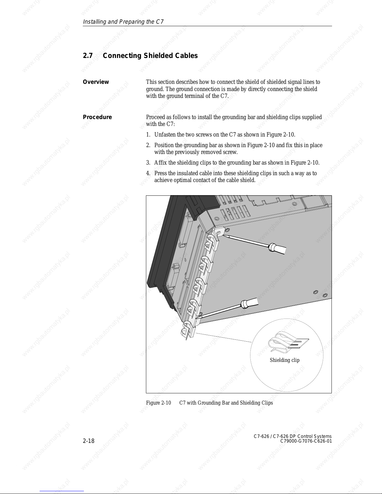
This section describes how to connect the shield of shielded signal lines to
ground. The ground connection is made by directly connecting the shield
with the ground terminal of the C7.
Proceed as follows to install the grounding bar and shielding clips supplied
with the C7:
1. Unfasten the two screws on the C7 as shown in Figure 2-10.
2. Position the grounding bar as shown in Figure 2-10 and fix this in place
with the previously removed screw.
3. Affix the shielding clips to the grounding bar as shown in Figure 2-10.
4. Press the insulated cable into these shielding clips in such a way as to
achieve optimal contact of the cable shield.
Shielding clip
Figure 2-10 C7 with Grounding Bar and Shielding Clips
Overview
Procedure
Installing and Preparing the C7
Page 37
2
2-19
C7-626 / C7-626 DP Control Systems
C79000-G7076-C626-01
2.8 Keying Connectors
A set of connectors with solid and profiled coding keys can be ordered as C7
accessories (see Section 2.1 under Accessories). This section describes how
to key the connectors.
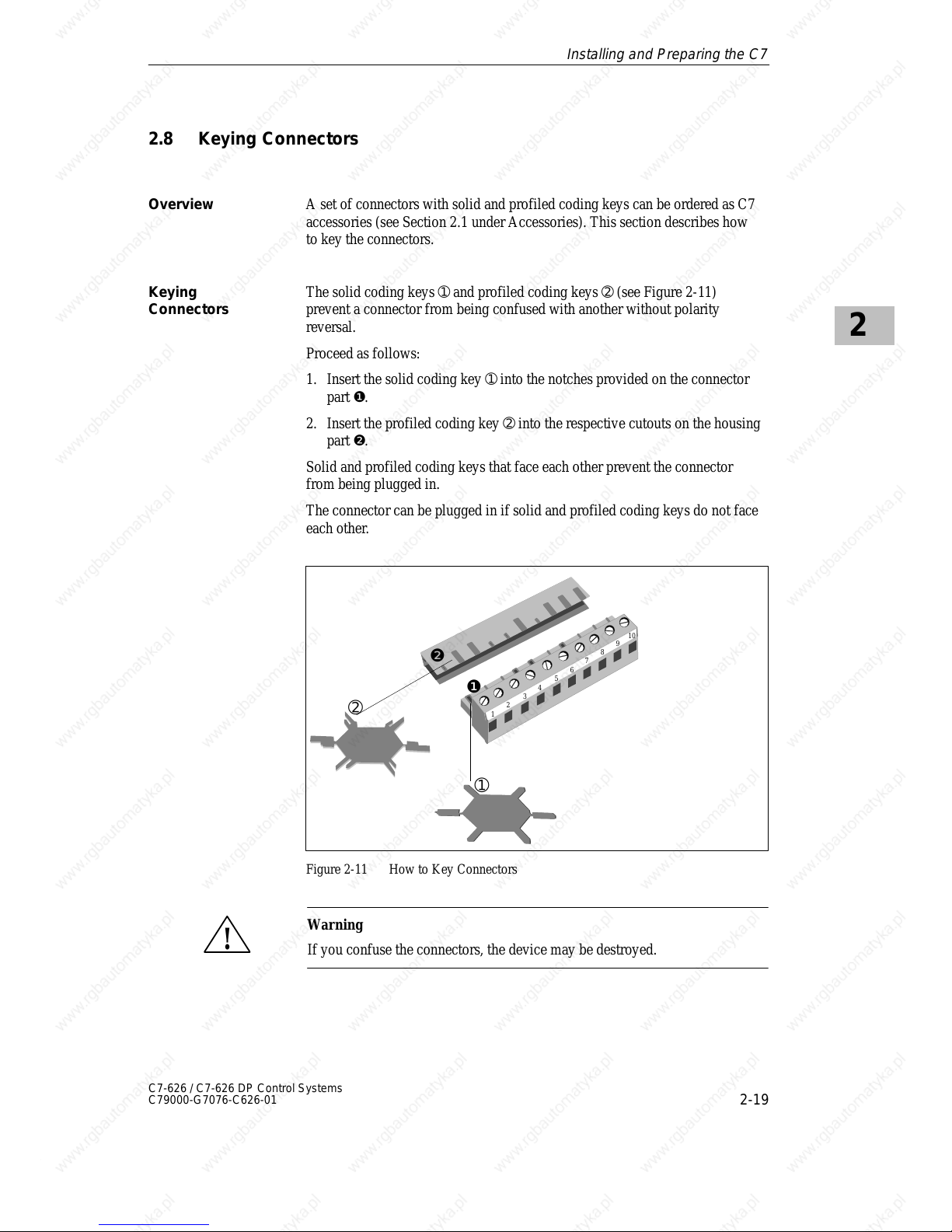
The solid coding keys ➀ and profiled coding keys ➁ (see Figure 2-11)
prevent a connector from being confused with another without polarity
reversal.
Proceed as follows:
1. Insert the solid coding key ➀ into the notches provided on the connector
part ❶.
2. Insert the profiled coding key ➁ into the respective cutouts on the housing
part ❷.
Solid and profiled coding keys that face each other prevent the connector
from being plugged in.
The connector can be plugged in if solid and profiled coding keys do not face
each other.
1
2
3
4
5
6
7
8
9
10
➀
❶
❷
➁
Figure 2-11 How to Key Connectors
!
Warning
If you confuse the connectors, the device may be destroyed.
Overview
Keying
Connectors
Installing and Preparing the C7
Page 38
2
2-20
C7-626 / C7-626 DP Control Systems
C79000-G7076-C626-01
2.9 Arrangement of Additional S7-300 Modules
You can connect further S7-300 modules to the C7 via the IM 360 interface
of the C7.
The manual /70/ describes how to install S7-300 modules.
An IM 361 module of the S7-300 system must be connected to the C7.
You can connect an additional I/O as follows:
1. Install the additional I/O as described for racks 1 to 3 in the manual /70/.
2. Connect the C7 to the IM 361 via the IM standard cable (see also
Figure 2-8 for connecting the C7).
When the C7 is first started up, it detects any additional connected modules.
The C7 has an integral IM 360 interface module for I/O expansion with an
external S7 standard I/O. This interface module is characterized by the
following features:
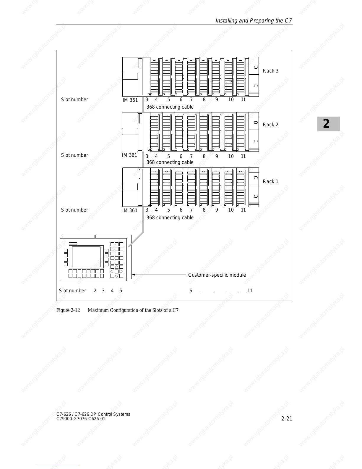
S Data transmission from the IM 360 to the IM 361 of the first rack
expansion via a 368 connecting cable.
S Maximum distance between IM 360 and IM 361: 10 m
You can expand your C7 by up to three mounting racks using the IM 360
interface module.
Additional S7-300
Modules
Prerequisite
Connecting
Additional I/Os
IM 360 Interface
Module
Installing and Preparing the C7
Page 39
2
2-21
C7-626 / C7-626 DP Control Systems
C79000-G7076-C626-01
368 connecting cable
368 connecting cable
368 connecting cable
2345 6 . . . 11
Rack 3
34567891011
34567891011
Slot number 3 4 5 6 7 8 9 10 11
Slot number
Slot number
Slot number
Rack 2
Rack 1
Customer-specific module
IM 361
.
IM 361
IM 361
Figure 2-12 Maximum Configuration of the Slots of a C7
Installing and Preparing the C7
Page 40
2
2-22
C7-626 / C7-626 DP Control Systems
C79000-G7076-C626-01
2.10 C7 Clocks
A C7 system has two clocks:
S One clock in the C7 CPU
S One clock in the C7 OP
The clock in the C7 CPU is an integral “real-time clock” (hardware clock).
This clock is independent of the clock in the C7 OP.
The clock is supplied with the following value set:
DT#1994-01-01-00:00:00.
As an integrated clock, the C7 CPU clock can also function as the master
clock within the C7 I/O configuration (see also Section 3.4.6 in Volume 2).
You can set and read the clock in the following ways:
S With the programming device (PG) using STEP 7
or
S In the user program with SFC0 “SET_CLK”. With SFC1 “READ_CLK”,
you can read the current time of day (see the reference manual /235/).
The C7 must always be backed up with a battery. The clocks in the C7
continue to run during power off.
The clock in the C7 OP is independent of the clock in the C7 CPU.
The clock is supplied with the following value set:
01.01.94 -00:00.
The clock time can be set:
S Via the user program and interface block, or
S On-line by operator input if the special display “Clock Time/Date” has
been configured and selected (see Volume 2, Section 6.7.1).
Overview
Clock in the
C7 CPU
Setting the C7 CPU
Clock
Master Clock
Setting and
Reading the Clock
in the Control
Section
Clock During
Power Off
Clock in the C7 OP
Section
Setting the O/I
Clock
Setting and
Reading the Clock
in the C7 OP
Section
Installing and Preparing the C7
Page 41
2
2-23
C7-626 / C7-626 DP Control Systems
C79000-G7076-C626-01
The C7 CPU provides you with a run-time meter.
You can use this meter to keep count of the operating hours of the C7 CPU or
of any controlled equipment.
You program the run-time meter in the user program with the SFCs
2 “SET_RTM”, 3 “CTRL_RTM” and 4 “READ_RTM” (see the reference
manual /235/).
Run-Time Meter
Installing and Preparing the C7
Page 42
2
2-24
C7-626 / C7-626 DP Control Systems
C79000-G7076-C626-01
2.11 Starting Up
The C7 comes supplied with a preloaded configuration. You can therefore
carry out a startup with the existing configuration.
However, if the configuration no longer exists (for example, after a reset),
you must carry out a startup without any configuration.
This section explains how to proceed in these cases.
Overview
Installing and Preparing the C7
Page 43
2
2-25
C7-626 / C7-626 DP Control Systems
C79000-G7076-C626-01
2.11.1 With a Loaded Configuration in the C7 OP
After applying the power supply the C7 carries out a self-test. The test checks
the functionality of the most important device components and displays the
results of the test via the LED status and the display screen. The following
startup will be carried out:
1. The C7 carries out a self test after power on.
2. The C7 carries out an operating system test for both parts (C7 CPU and
C7 OP).
3. During the start-up phase (1 and 2) the C7 CPU remains in STOP mode.
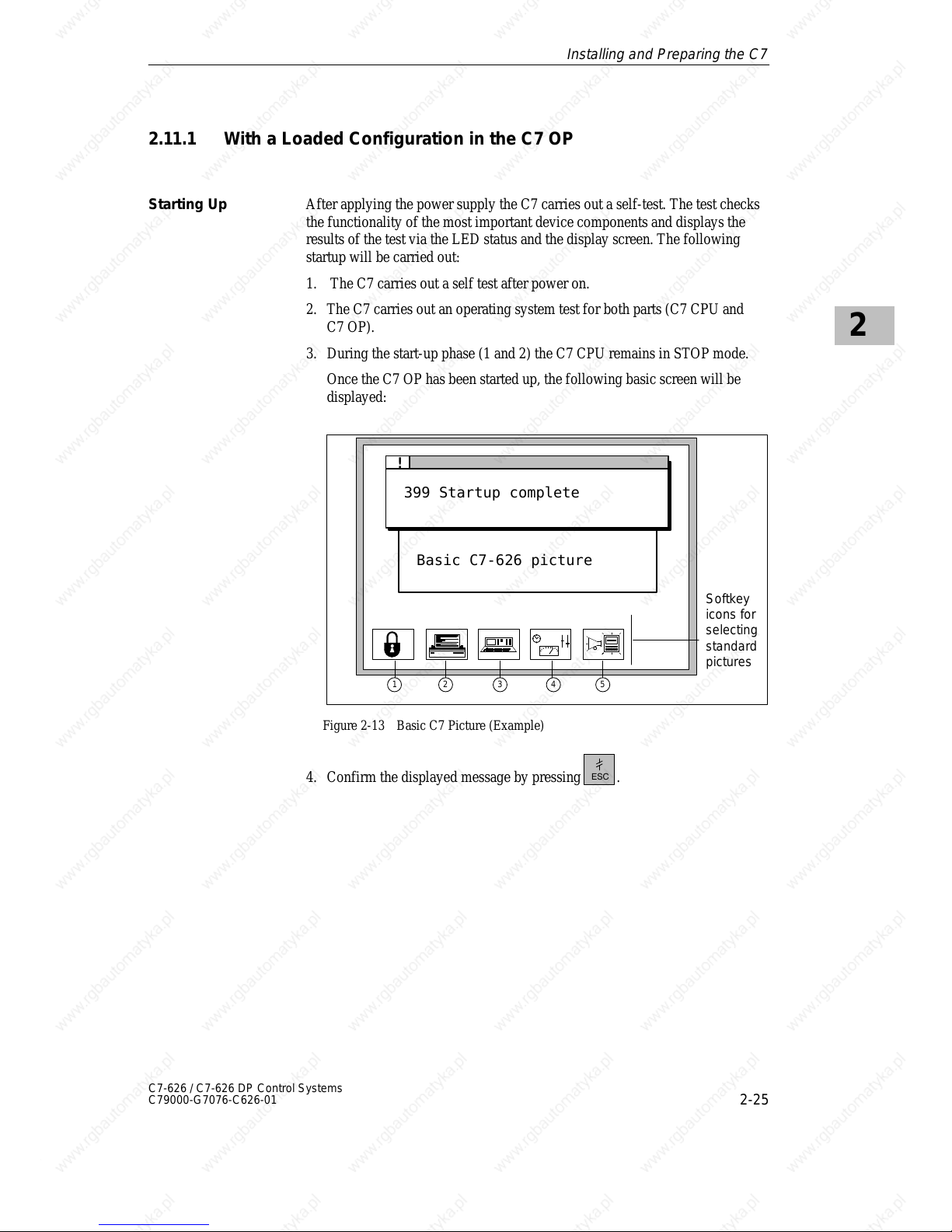
Once the C7 OP has been started up, the following basic screen will be
displayed:
399 Startup complete
!
Basic C7-626 picture
1 2 3 4 5
Softkey
icons for
selecting
standard
pictures
Figure 2-13 Basic C7 Picture (Example)
4. Confirm the displayed message by pressing
.
Starting Up
Installing and Preparing the C7
Page 44
2
2-26
C7-626 / C7-626 DP Control Systems
C79000-G7076-C626-01
2.11.2 Without a Loaded Configuration in the C7 OP
Load the basic configuration so that the explanations in this manual relate to
this configuration.
Note
When starting up without a configuration, you must load a configuration via
the V.24 serial interface.
Proceed as follows:
1. Connect the V.24 serial interface of the C7 OP (see Figure 2-8) to the
programming device/PC via a programming device/PC standard cable.
2. Switch on the C7 power supply.
As no configuration is loaded, the C7 automatically goes into transfer
mode and waits for a data transfer.
3. Transfer the configuration from the programming device/PC to the
C7 OP.
The firmware of the C7 OP is automatically transferred as well.
After a successful transfer, the C7 OP is restarted.
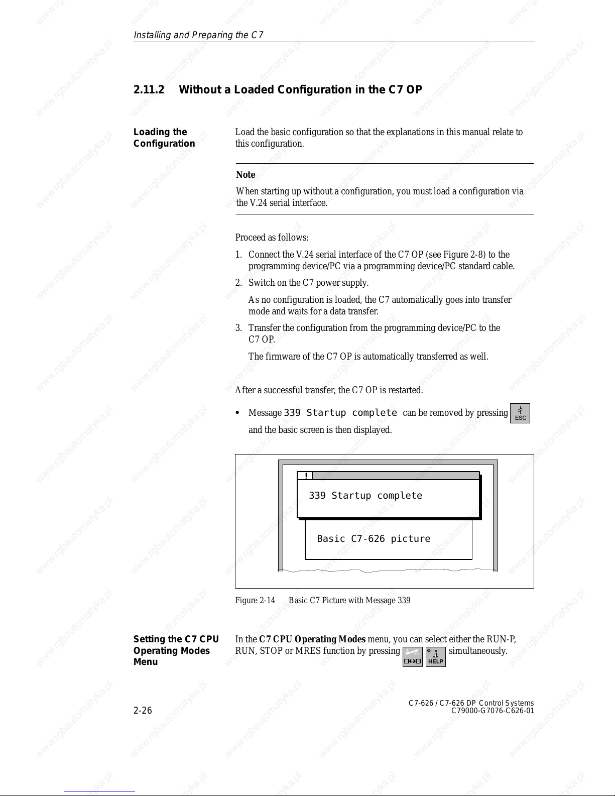
S Message 339 Startup complete can be removed by pressing
and the basic screen is then displayed.
339 Startup complete
!
Basic C7-626 picture
Figure 2-14 Basic C7 Picture with Message 339
In the C7 CPU Operating Modes menu, you can select either the RUN-P,
RUN, STOP or MRES function by pressing
A–Z
simultaneously.
Loading the
Configuration
Setting the C7 CPU
Operating Modes
Menu
Installing and Preparing the C7
Page 45
2
2-27
C7-626 / C7-626 DP Control Systems
C79000-G7076-C626-01
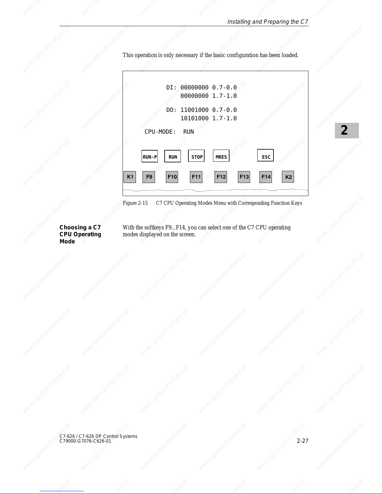
This operation is only necessary if the basic configuration has been loaded.
DI: 00000000 0.7-0.0
00000000 1.7-1.0
DO: 11001000 0.7-0.0
10101000 1.7-1.0
CPU-MODE: RUN
RUN-P RUN STOP MRES ESC
Figure 2-15 C7 CPU Operating Modes Menu with Corresponding Function Keys
With the softkeys F9...F14, you can select one of the C7 CPU operating
modes displayed on the screen.
Choosing a C7
CPU Operating
Mode
Installing and Preparing the C7
Page 46
2
2-28
C7-626 / C7-626 DP Control Systems
C79000-G7076-C626-01
2.12 Status and Error LEDs on the C7
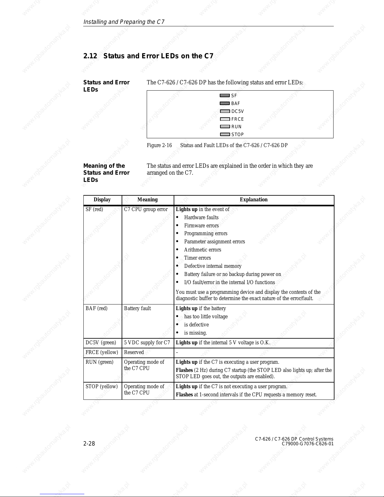
The C7-626 / C7-626 DP has the following status and error LEDs:
SF
BAF
DC5V
FRCE
RUN
STOP
Figure 2-16 Status and Fault LEDs of the C7-626 / C7-626 DP
The status and error LEDs are explained in the order in which they are
arranged on the C7.
Display Meaning Explanation
SF (red) C7 CPU group error Lights up in the event of
S Hardware faults
S Firmware errors
S Programming errors
S Parameter assignment errors
S Arithmetic errors
S Timer errors
S Defective internal memory
S Battery failure or no backup during power on
S I/O fault/error in the internal I/O functions
You must use a programming device and display the contents of the
diagnostic buffer to determine the exact nature of the error/fault.
BAF (red) Battery fault Lights up if the battery
S has too little voltage
S is defective
S is missing.
DC5V (green) 5 VDC supply for C7 Lights up if the internal 5 V voltage is O.K.
FRCE (yellow) Reserved –
RUN (green) Operating mode of
the C7 CPU
Lights up if the C7 is executing a user program.
Flashes (2 Hz) during C7 startup (the STOP LED also lights up; after the
STOP LED goes out, the outputs are enabled).
STOP (yellow) Operating mode of
the C7 CPU
Lights up if the C7 is not executing a user program.
Flashes at 1-second intervals if the CPU requests a memory reset.
Status and Error
LEDs
Meaning of the
Status and Error
LEDs
Installing and Preparing the C7
Page 47
3-1
C7-626 / C7-626 DP Control Systems
C79000-G7076-C626-01
Configuring MPI Networks and
PROFIBUS-DP Networks
! Y ou can
S integrate the C7-626 via the MPI into an MPI network.
S integrate the C7-626 DP via the MPI into an MPI network or set up a
PROFIBUS-DP network via the PROFIBUS-DP interface.
SINEC-L2 DP is the PROFIBUS DP for SIEMENS devices.
The setup of an MPI network is basically the same as the setup of a
PROFIBUS-DP network. That is, the same setup rules apply, and you use the
same components for setting up both networks. There are only exceptions if
you set a transmission rate > 1.5 Mbps in the PROFIBUS-DP network. In this
case, you require special components which will be referred to in the relevant
section.
Since the setup of an MPI network does not differ from that of a
PROFIBUS-DP network, this section will simply refer to setting up a
network.
You must assign MPI/L2 addresses to the individual nodes of an MPI or
PROFIBUS-DP network to enable them to communicate with each other.
How you assign these addresses and what rules you must observe are
described in the STEP 7 manuals.
In Section
You Will Find On Page
3.1 Setting Up a Network 3-2
3.2 Rules for Configuring a Network 3-5
3.3 Cable Lengths 3-12
3.4 Network Components 3-15
3.5 Bus Connectors 3-17
3.5.1 PROFIBUS Bus Connector 3-18
3.5.2 Bus Connector 6ES7 972-0B.20-0XA0 3-19
3.5.3 Bus Connector 6ES7 972-0B.10-0XA0 3-22
3.5.4 Plugging the Bus Connector into the Module 3-24
3.6 Starting Up the PROFIBUS DP 3-25
MPI/PROFIBUS DP
SINEC-L2 DP =
PROFIBUS DP
The Same Setup
Setting up the
Communication
Summary of
Sections
3
Page 48
3
3-2
C7-626 / C7-626 DP Control Systems
C79000-G7076-C626-01
3.1 Setting Up a Network
The interface of the C7 for connecting, for example, programming devices, is
called a multipoint interface since several devices can communicate with the
C7 via this interface (that is, communication can take place from several
points).
The MPI transmission rate of the C7-626 and C7-626 DP is fixed at
187.5 Kbps.
Digital, analog and intelligent modules, as well as a wide range of field
devices according to DIN E 19245 Part 3 such as drives or valve islands, are
stored locally from the automation system to the process – up to a distance of
23 km.
The modules and field devices are thus connected to the automation system
via the field bus PROFIBUS DP and addressed as local I/Os.
The DP transmission rate of the C7-626 DP can be set up to 12 Mbps.
The following table shows which nodes you can use to set up a network.
MPI
PROFIBUS DP
(only with C7-626 DP)
Programming devices (PG/PC) Programming device (PG/PC)
Operator interface devices (OP) Operator interface devices (OP)
S7-300/M7-300 DP masters (C7-CPU DP)
S7-400/M7-400 Additional DP masters
Additional C7 devices DP slaves
FMs, CPs
Convention: all devices that you connect in an MPI network are called nodes.
Note that the C7 occupies two MPI addresses and therefore already consists
internally of two nodes.
A segment is a bus line between two terminating resistances. A segment can
contain up to 32 nodes.
Definition:
Multipoint
Interface (MPI)
MPI Transmission
Rate
Definition:
PROFIBUS DP
DP Transmission
Rate
Connectable
Nodes
Device / Node
Segment
Configuring MPI Networks and PROFIBUS-DP Networks
Page 49
3
3-3
C7-626 / C7-626 DP Control Systems
C79000-G7076-C626-01
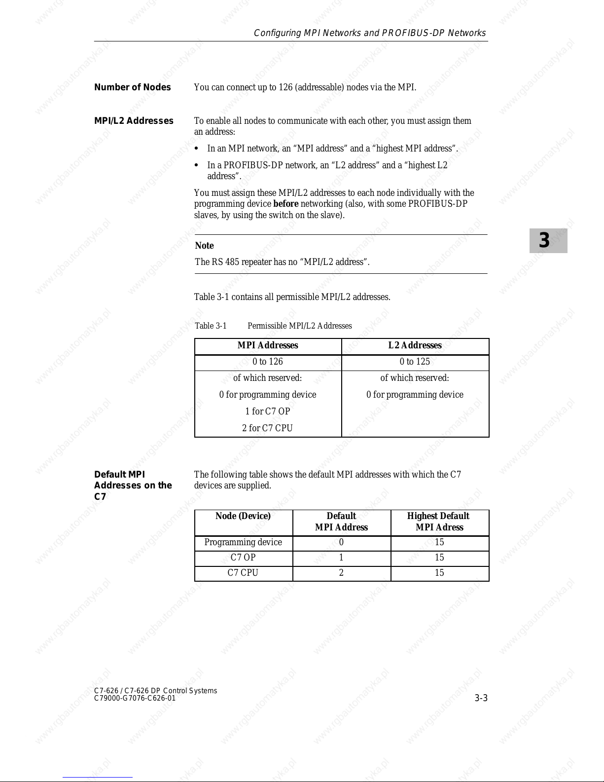
You can connect up to 126 (addressable) nodes via the MPI.
To enable all nodes to communicate with each other, you must assign them
an address:
S In an MPI network, an “MPI address” and a “highest MPI address”.
S In a PROFIBUS-DP network, an “L2 address” and a “highest L2
address”.
You must assign these MPI/L2 addresses to each node individually with the
programming device before networking (also, with some PROFIBUS-DP
slaves, by using the switch on the slave).
Note
The RS 485 repeater has no “MPI/L2 address”.
Table 3-1 contains all permissible MPI/L2 addresses.
Table 3-1 Permissible MPI/L2 Addresses
MPI Addresses L2 Addresses
0 to 126 0 to 125
of which reserved:
0 for programming device
1 for C7 OP
2 for C7 CPU
of which reserved:
0 for programming device
The following table shows the default MPI addresses with which the C7
devices are supplied.
Node (Device)
Default
MPI Address
Highest Default
MPI Adress
Programming device 0 15
C7 OP 1 15
C7 CPU 2 15
Number of Nodes
MPI/L2 Addresses
Default MPI
Addresses on the
C7
Configuring MPI Networks and PROFIBUS-DP Networks
Page 50
3
3-4
C7-626 / C7-626 DP Control Systems
C79000-G7076-C626-01
Please observe the following rules before assigning MPI/L2 addresses:
S All MPI/L2 addresses in a network must be different
S The highest possible MPI/L2 address must be > the largest actual address
and must be the same for all nodes. (Exception: connecting a
programming device to several nodes; see Chapter 4).
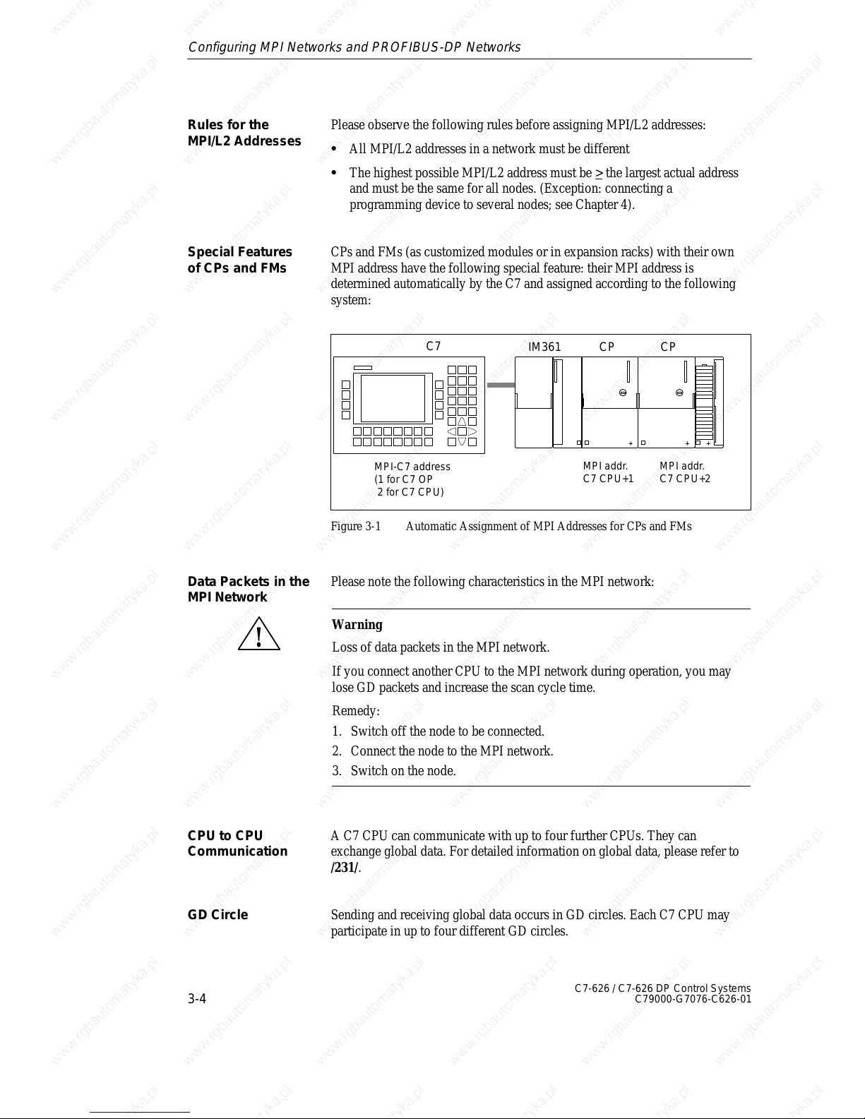
CPs and FMs (as customized modules or in expansion racks) with their own
MPI address have the following special feature: their MPI address is
determined automatically by the C7 and assigned according to the following
system:
MPI-C7 address
(1 for C7 OP
2 for C7 CPU)
MPI addr.
C7 CPU+1
MPI addr.
C7 CPU+2
C7
CP
CPIM361
Figure 3-1 Automatic Assignment of MPI Addresses for CPs and FMs
Please note the following characteristics in the MPI network:
!
Warning
Loss of data packets in the MPI network.
If you connect another CPU to the MPI network during operation, you may
lose GD packets and increase the scan cycle time.
Remedy:
1. Switch off the node to be connected.
2. Connect the node to the MPI network.
3. Switch on the node.
A C7 CPU can communicate with up to four further CPUs. They can
exchange global data. For detailed information on global data, please refer to
/231/.
Sending and receiving global data occurs in GD circles. Each C7 CPU may
participate in up to four different GD circles.
Rules for the
MPI/L2 Addresses
Special Features
of CPs and FMs
Data Packets in the
MPI Network
CPU to CPU
Communication
GD Circle
Configuring MPI Networks and PROFIBUS-DP Networks
Page 51
3
3-5
C7-626 / C7-626 DP Control Systems
C79000-G7076-C626-01
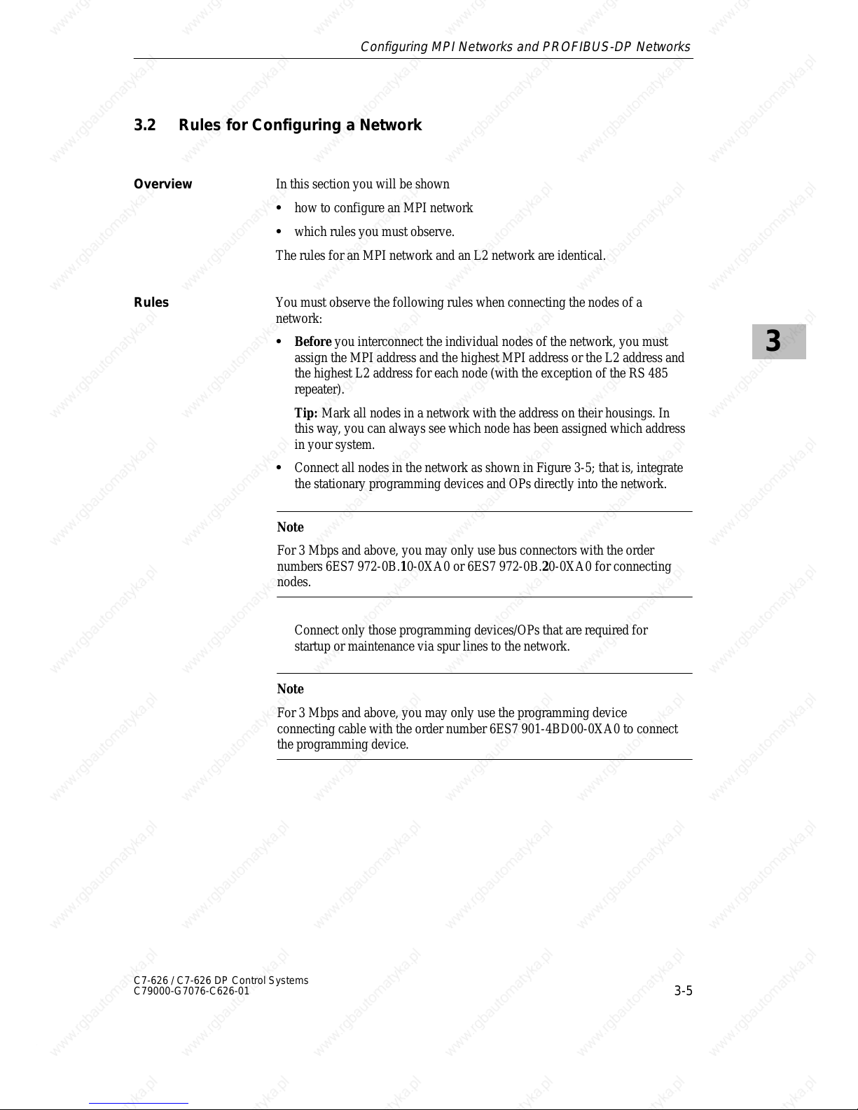
3.2 Rules for Configuring a Network
In this section you will be shown
S how to configure an MPI network
S which rules you must observe.
The rules for an MPI network and an L2 network are identical.
You must observe the following rules when connecting the nodes of a
network:
S Before you interconnect the individual nodes of the network, you must
assign the MPI address and the highest MPI address or the L2 address and
the highest L2 address for each node (with the exception of the RS 485
repeater).
Tip: Mark all nodes in a network with the address on their housings. In
this way, you can always see which node has been assigned which address
in your system.
S Connect all nodes in the network as shown in Figure 3-5; that is, integrate
the stationary programming devices and OPs directly into the network.
Note
For 3 Mbps and above, you may only use bus connectors with the order
numbers 6ES7 972-0B.10-0XA0 or 6ES7 972-0B.20-0XA0 for connecting
nodes.
Connect only those programming devices/OPs that are required for
startup or maintenance via spur lines to the network.
Note
For 3 Mbps and above, you may only use the programming device
connecting cable with the order number 6ES7 901-4BD00-0XA0 to connect
the programming device.
Overview
Rules
Configuring MPI Networks and PROFIBUS-DP Networks
Page 52
3
3-6
C7-626 / C7-626 DP Control Systems
C79000-G7076-C626-01
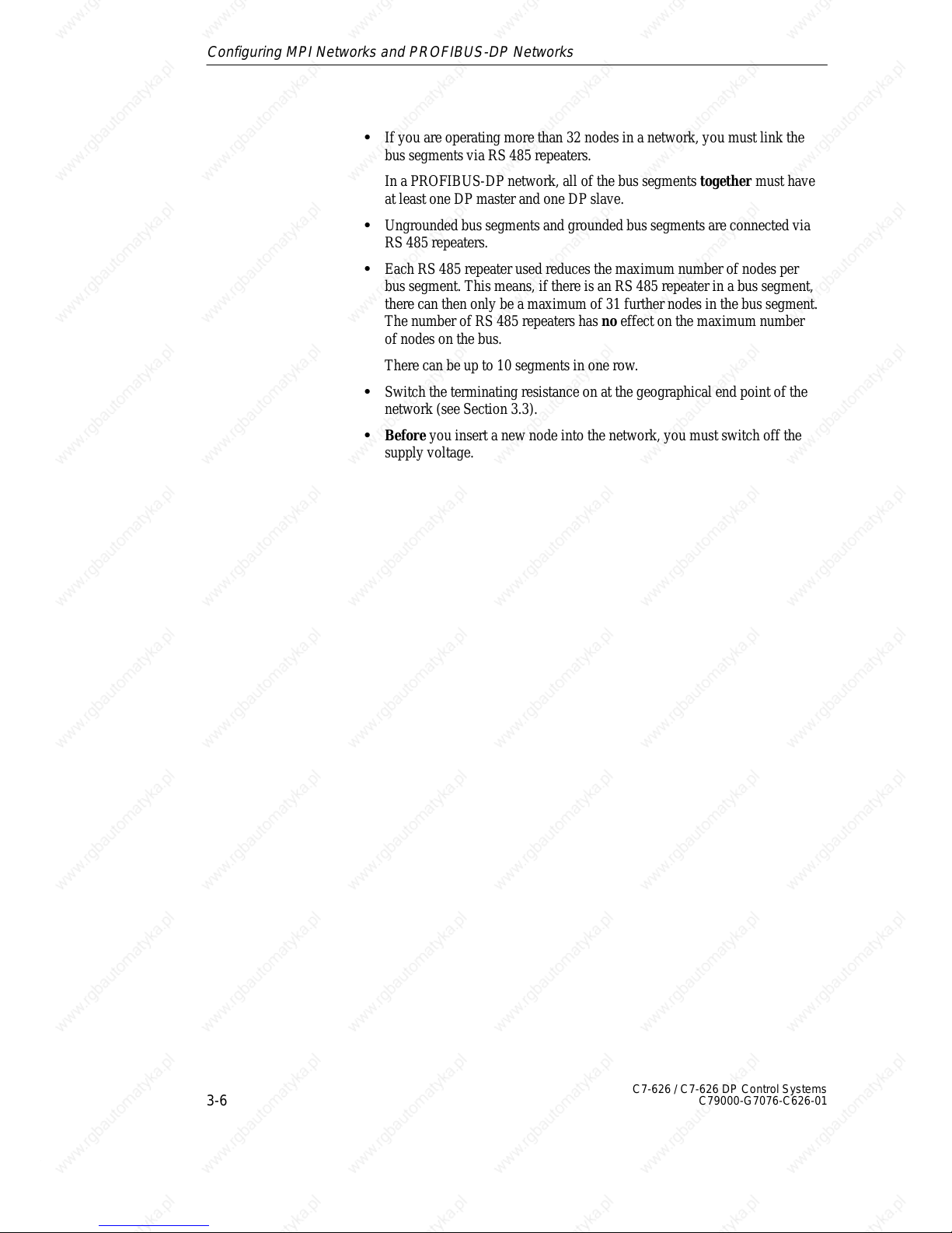
S If you are operating more than 32 nodes in a network, you must link the
bus segments via RS 485 repeaters.
In a PROFIBUS-DP network, all of the bus segments together must have
at least one DP master and one DP slave.
S Ungrounded bus segments and grounded bus segments are connected via
RS 485 repeaters.
S Each RS 485 repeater used reduces the maximum number of nodes per
bus segment. This means, if there is an RS 485 repeater in a bus segment,
there can then only be a maximum of 31 further nodes in the bus segment.
The number of RS 485 repeaters has no effect on the maximum number
of nodes on the bus.
There can be up to 10 segments in one row.
S Switch the terminating resistance on at the geographical end point of the
network (see Section 3.3).
S Before you insert a new node into the network, you must switch off the
supply voltage.
Configuring MPI Networks and PROFIBUS-DP Networks
Page 53
3
3-7
C7-626 / C7-626 DP Control Systems
C79000-G7076-C626-01
The MPI addresses set at the factory should not be assigned as fixed node
addresses since, otherwise, address conflicts (double MPI addresses) can
arise when devices are replaced or the network is expanded.
S Reserve the MPI address “0” for a service programming device.
S Reserve the address “1” for the C7 OP.
S Reserve the address “2” for the C7 CPU.
This avoids double assignment of MPI addresses after installing a further
preset C7 or S7-300 in the MPI network (for example, when replacing a C7).
Reserve the L2 address “0” for a service programming device which may be
temporarily connected to the L2-DP network at a later stage if required. You
should therefore assign other L2 addresses to the programming devices
included in the L2-DP network.
You connect the individual nodes via the bus connectors and the PROFIBUS
bus cable. Remember to provide for the nodes a bus connector with
programming device socket to which a programming device can be
connected if required (see also Section 3.5).
Use the RS 485 repeater for connections between segments or for extending
cables.
See the reference manual /71/ for details of how to install and use a repeater.
A cable must be terminated with a surge impedance. To do this, switch on the
terminating resistance at the first and last node of the network.
At least one of these two nodes must be supplied with power.
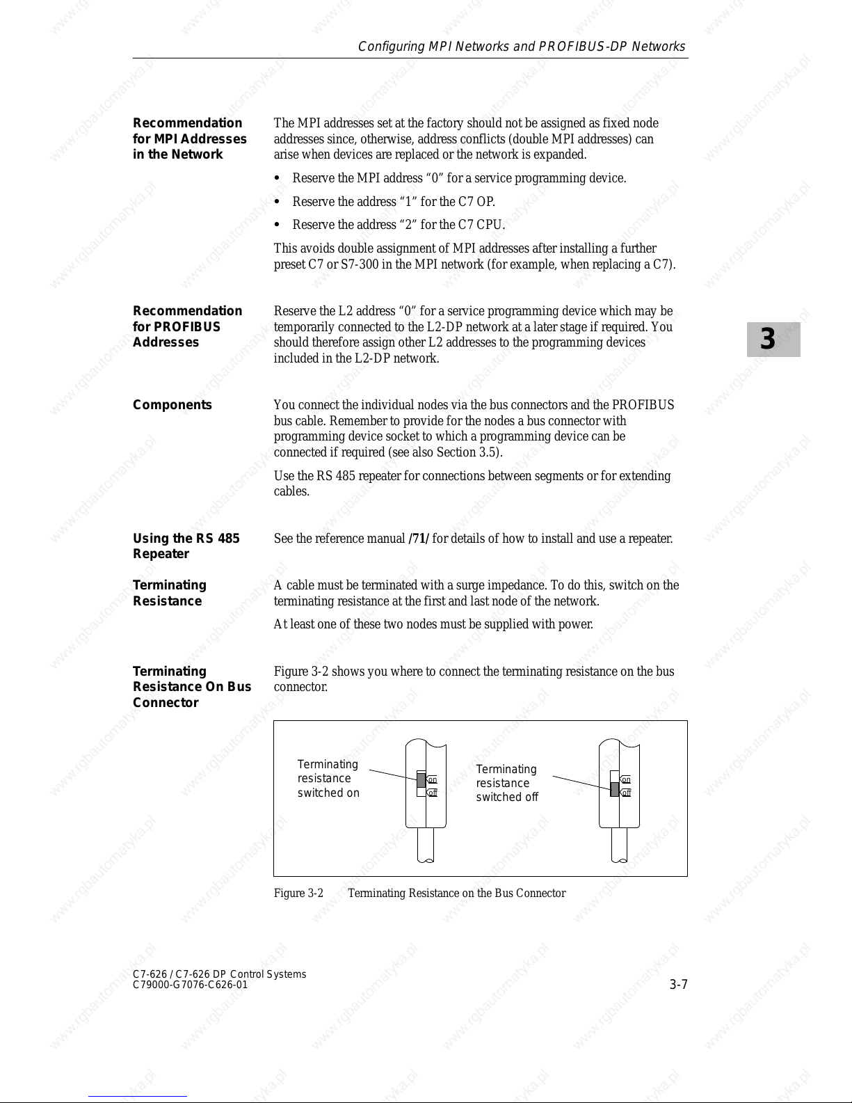
Figure 3-2 shows you where to connect the terminating resistance on the bus
connector.
on
off
Terminating
resistance
switched off
on
off
Terminating
resistance
switched on
Figure 3-2 Terminating Resistance on the Bus Connector
Recommendation
for MPI Addresses
in the Network
Recommendation
for PROFIBUS
Addresses
Components
Using the RS 485
Repeater
T erminating
Resistance
T erminating
Resistance On Bus
Connector
Configuring MPI Networks and PROFIBUS-DP Networks
Page 54
3
3-8
C7-626 / C7-626 DP Control Systems
C79000-G7076-C626-01
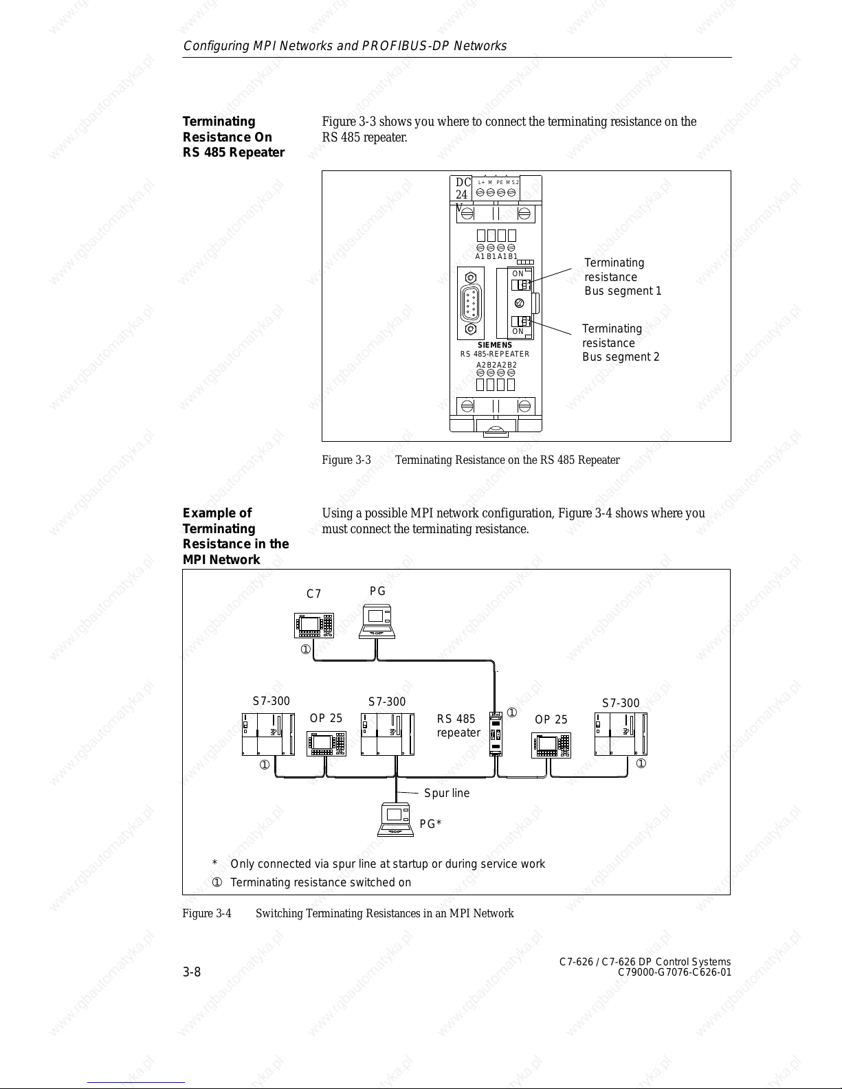
Figure 3-3 shows you where to connect the terminating resistance on the
RS 485 repeater.
DC
24
V
L+ M PE M 5.2
A1 B1 A1 B1
A2B2A2B2
SIEMENS
RS 485-REPEATER
ON
ON
Terminating
resistance
Bus segment 1
Terminating
resistance
Bus segment 2
Figure 3-3 Terminating Resistance on the RS 485 Repeater
Using a possible MPI network configuration, Figure 3-4 shows where you
must connect the terminating resistance.
RS 485
repeater
➀
➀
➀
➀ Terminating resistance switched on
S7-300
S7-300
C7
Spur line
S7-300
➀
OP 25
OP 25
PG
PG*
* Only connected via spur line at startup or during service work
Figure 3-4 Switching Terminating Resistances in an MPI Network
Terminating
Resistance On
RS 485 Repeater
Example of
T erminating
Resistance in the
MPI Network
Configuring MPI Networks and PROFIBUS-DP Networks
Page 55
3
3-9
C7-626 / C7-626 DP Control Systems
C79000-G7076-C626-01
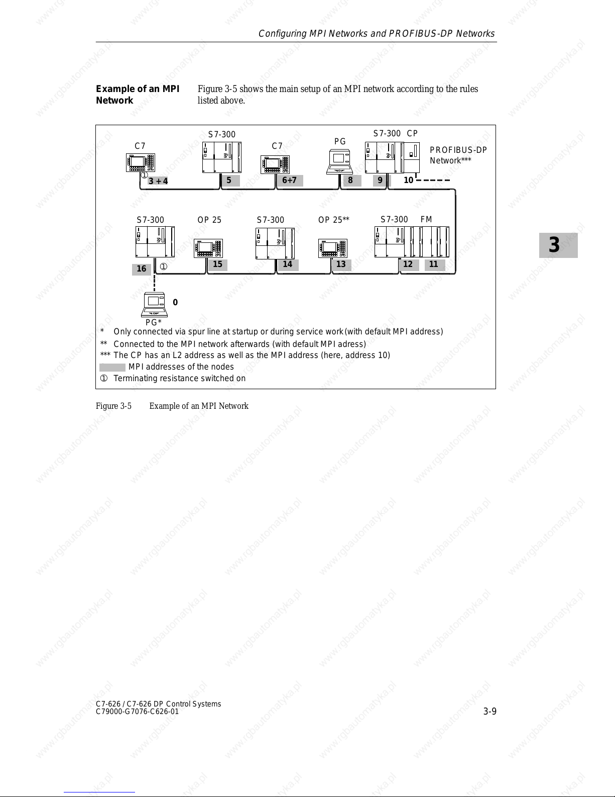
Figure 3-5 shows the main setup of an MPI network according to the rules
listed above.
S7-300
S7-300S7-300
PG*
0
16
0 ... x MPI addresses of the nodes
12131415
5 86+7
C7 C7
PG
9
S7-300 CP
PROFIBUS-DP
Network***
10
S7-300 FM
11
* Only connected via spur line at startup or during service work(with default MPI address)
OP 25**OP 25
** Connected to the MPI network afterwards (with default MPI adress)
*** The CP has an L2 address as well as the MPI address (here, address 10)
➀
➀ Terminating resistance switched on
➀
3 + 4
Figure 3-5 Example of an MPI Network
Example of an MPI
Network
Configuring MPI Networks and PROFIBUS-DP Networks
Page 56
3
3-10
C7-626 / C7-626 DP Control Systems
C79000-G7076-C626-01
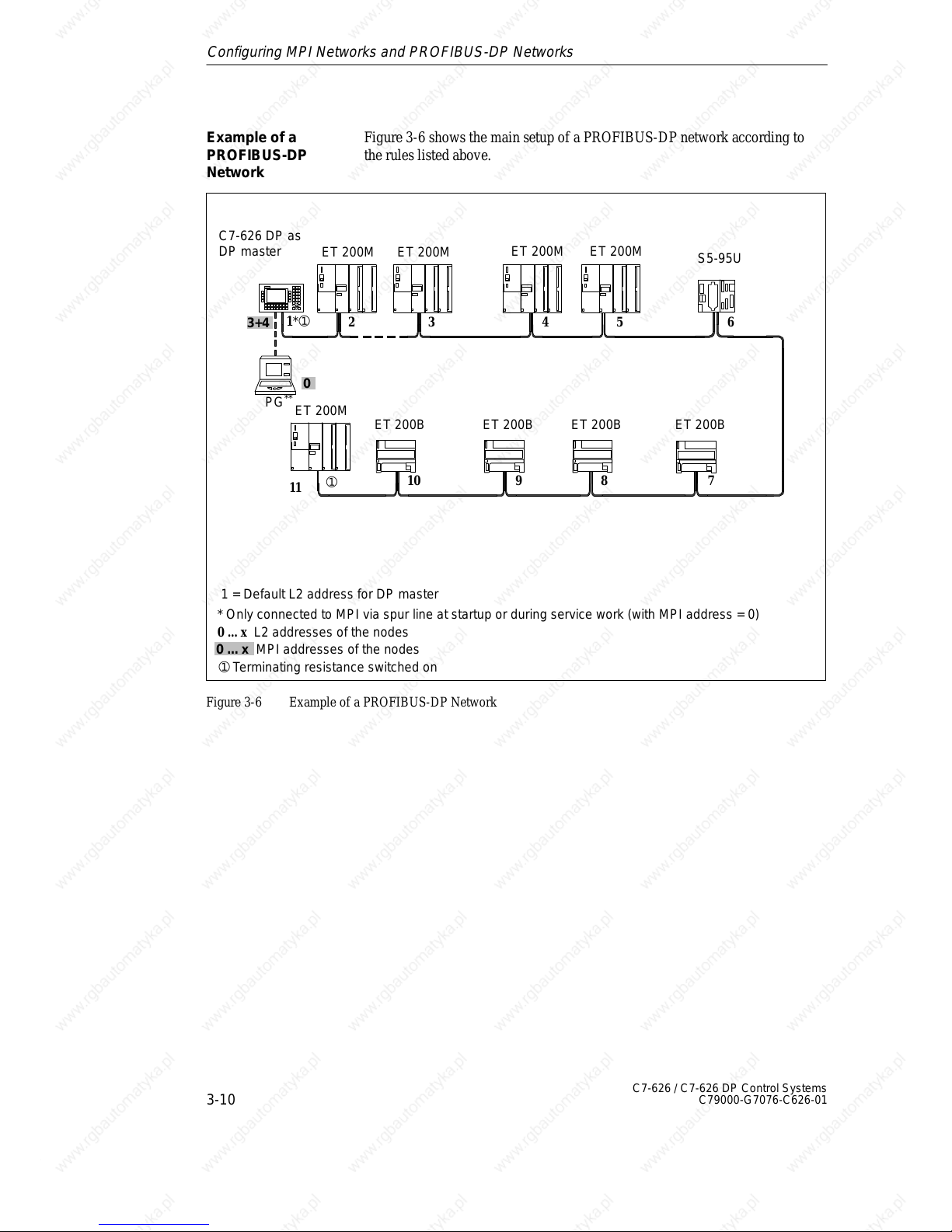
Figure 3-6 shows the main setup of a PROFIBUS-DP network according to
the rules listed above.
* Only connected to MPI via spur line at startup or during service work (with MPI address = 0)
0 ... x L2 addresses of the nodes
C7-626 DP as
DP master
ET 200M
0
11
78910
2
3456
ET 200M
S5-95U
ET 200BET 200B
➀
➀
➀ Terminating resistance switched on
ET 200M
ET 200M
ET 200M
ET 200B ET 200B
PG
**
1 = Default L2 address for DP master
1*
3+4
0 ... x MPI addresses of the nodes
Figure 3-6 Example of a PROFIBUS-DP Network
Example of a
PROFIBUS-DP
Network
Configuring MPI Networks and PROFIBUS-DP Networks
Page 57
3
3-11
C7-626 / C7-626 DP Control Systems
C79000-G7076-C626-01
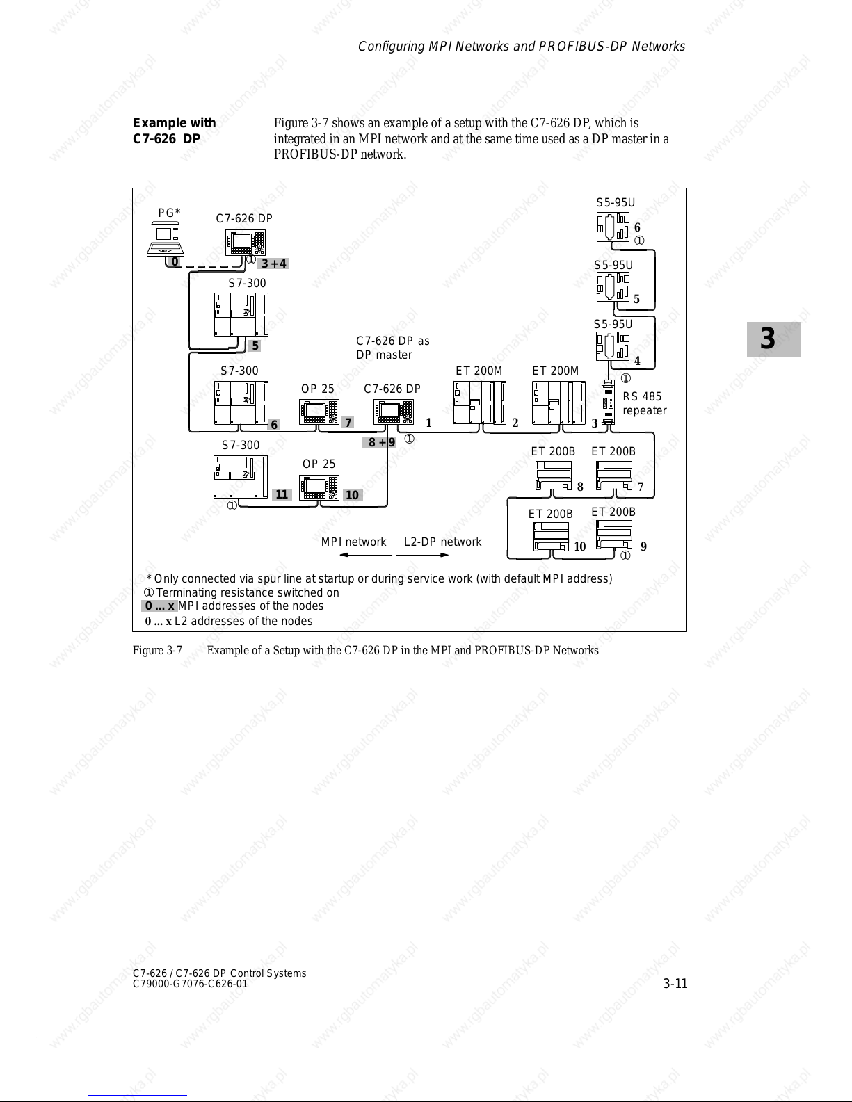
Figure 3-7 shows an example of a setup with the C7-626 DP, which is
integrated in an MPI network and at the same time used as a DP master in a
PROFIBUS-DP network.
OP 25
C7-626 DP as
DP master
ET 200M
S5-95U
ET 200B
RS 485
repeater
PG*
S7-300
S7-300
S7-300
OP 25
ET 200M
S5-95U
ET 200B
➀ Terminating resistance switched on
* Only connected via spur line at startup or during service work (with default MPI address)
➀
➀
➀
L2-DP networkMPI network
S5-95U
➀
➀
ET 200B
ET 200B
3 + 4
5
6
7
8 + 9
10
12
3
4
5
6
87
10 9
0 ... x MPI addresses of the nodes
L2 addresses of the nodes
0
C7-626 DP
C7-626 DP
➀
11
Figure 3-7 Example of a Setup with the C7-626 DP in the MPI and PROFIBUS-DP Networks
Example with
C7-626 DP
Configuring MPI Networks and PROFIBUS-DP Networks
Page 58
3
3-12
C7-626 / C7-626 DP Control Systems
C79000-G7076-C626-01
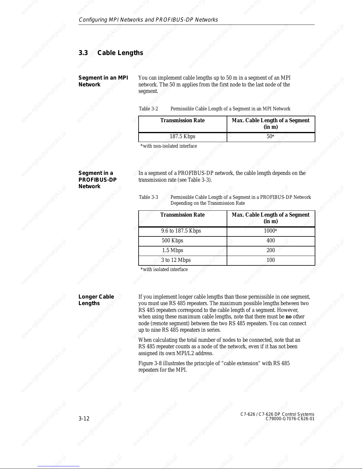
3.3 Cable Lengths
You can implement cable lengths up to 50 m in a segment of an MPI
network. The 50 m applies from the first node to the last node of the
segment.
Table 3-2 Permissible Cable Length of a Segment in an MPI Network
Transmission Rate Max. Cable Length of a Segment
(in m)
187.5 Kbps 50*
*with non-isolated interface
In a segment of a PROFIBUS-DP network, the cable length depends on the
transmission rate (see Table 3-3).
Table 3-3 Permissible Cable Length of a Segment in a PROFIBUS-DP Network
Depending on the Transmission Rate
Transmission Rate Max. Cable Length of a Segment
(in m)
9.6 to 187.5 Kbps 1000*
500 Kbps 400
1.5 Mbps 200
3 to 12 Mbps 100
*with isolated interface
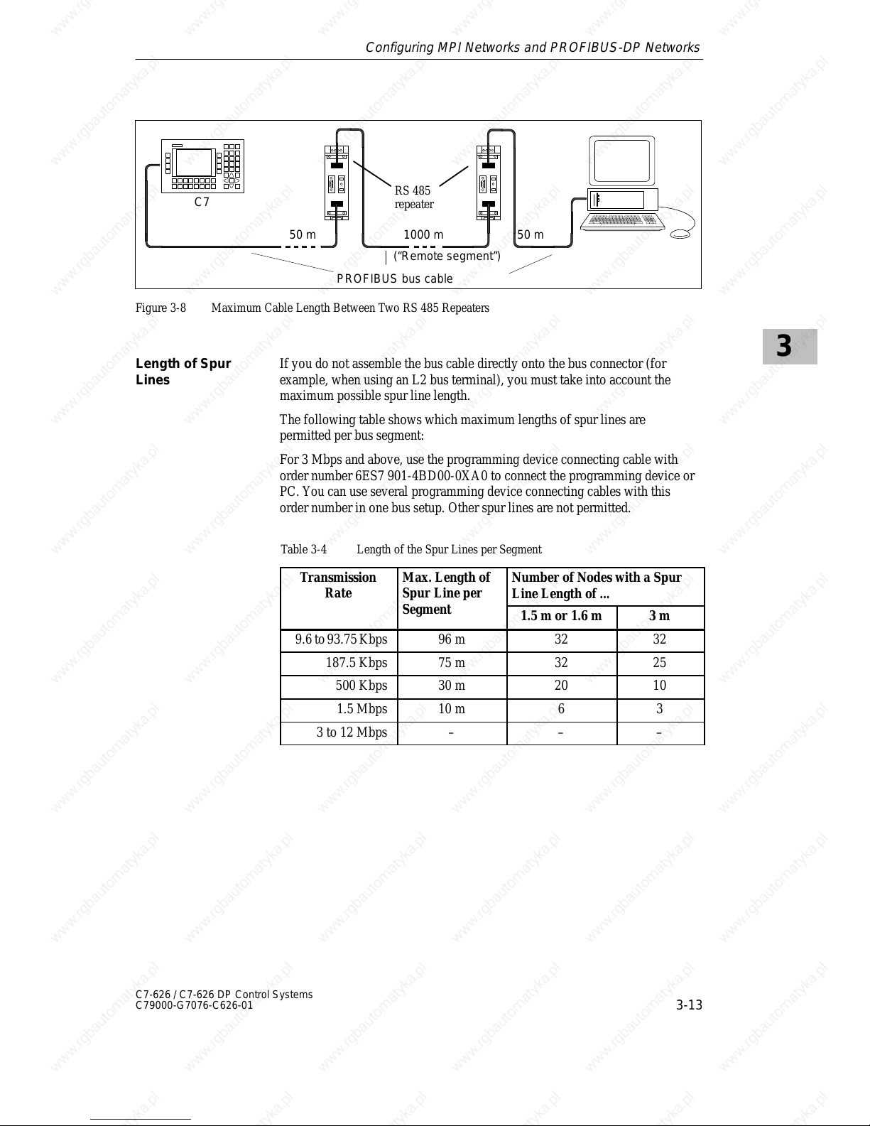
If you implement longer cable lengths than those permissible in one segment,
you must use RS 485 repeaters. The maximum possible lengths between two
RS 485 repeaters correspond to the cable length of a segment. However,
when using these maximum cable lengths, note that there must be no other
node (remote segment) between the two RS 485 repeaters. You can connect
up to nine RS 485 repeaters in series.
When calculating the total number of nodes to be connected, note that an
RS 485 repeater counts as a node of the network, even if it has not been
assigned its own MPI/L2 address.
Figure 3-8 illustrates the principle of “cable extension” with RS 485
repeaters for the MPI.
Segment in an MPI
Network
Segment in a
PROFIBUS-DP
Network
Longer Cable
Lengths
Configuring MPI Networks and PROFIBUS-DP Networks
Page 59
3
3-13
C7-626 / C7-626 DP Control Systems
C79000-G7076-C626-01
C7
50 m 1000 m 50 m
RS 485
repeater
PROFIBUS bus cable
(“Remote segment”)
Figure 3-8 Maximum Cable Length Between Two RS 485 Repeaters
If you do not assemble the bus cable directly onto the bus connector (for
example, when using an L2 bus terminal), you must take into account the
maximum possible spur line length.
The following table shows which maximum lengths of spur lines are
permitted per bus segment:
For 3 Mbps and above, use the programming device connecting cable with
order number 6ES7 901-4BD00-0XA0 to connect the programming device or
PC. You can use several programming device connecting cables with this
order number in one bus setup. Other spur lines are not permitted.
Table 3-4 Length of the Spur Lines per Segment
Transmission
Rate
Max. Length of
Spur Line per
Number of Nodes with a Spur
Line Length of ...
Segment
1.5 m or 1.6 m 3 m
9.6 to 93.75 Kbps 96 m 32 32
187.5 Kbps 75 m 32 25
500 Kbps 30 m 20 10
1.5 Mbps 10 m 6 3
3 to 12 Mbps – – –
Length of Spur
Lines
Configuring MPI Networks and PROFIBUS-DP Networks
Page 60
3
3-14
C7-626 / C7-626 DP Control Systems
C79000-G7076-C626-01
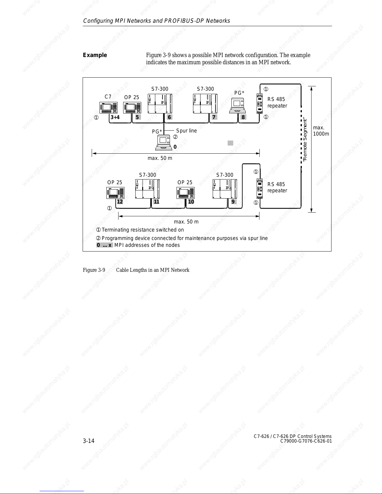
Figure 3-9 shows a possible MPI network configuration. The example
indicates the maximum possible distances in an MPI network.
RS 485
repeater
RS 485
repeater
max. 50 m
max. 50 m
max.
1000m
➀
➀
➀
➀
➀
➀
➀ Terminating resistance switched on
C7
S7-300 S7-300
S7-300 S7-300
Spur line
➁
➁ Programming device connected for maintenance purposes via spur line
0
12
0 ... x MPI addresses of the nodes
8
91011
3+4 5 6 7
OP 25
PG*
PG*
OP 25
OP 25
”Remote Segment”
Figure 3-9 Cable Lengths in an MPI Network
Example
Configuring MPI Networks and PROFIBUS-DP Networks
Page 61
3
3-15
C7-626 / C7-626 DP Control Systems
C79000-G7076-C626-01
3.4 Network Components
You require network components...
Table 3-5 Network Components
Purpose Component
... for setting up a network PROFIBUS bus cable
... for connecting a node to the
network
Bus connector
... for amplifying the signal
... for linking segments
RS 485 repeater
... for converting the signal to
fiber-optic transmission
(PROFIBUS DP network only)
Optical Link Module
... for connecting programming
devices/OPs to the network
Programming device cables
(spur lines)
We offer the following PROFIBUS bus cables:
Table 3-6 Bus Cables
PROFIBUS bus cable
PROFIBUS direct-buried cable
PROFIBUS drum cable
PROFIBUS bus cable with PE sheath (for food and drinks industry)
PROFIBUS bus cable for festooning
The PROFIBUS bus cable is a two-core, twisted and shielded cable with the
following characteristics:
Table 3-7 Characteristics of the PROFIBUS Bus Cable
Features Values
Surge impedance Approx. 135 to 160 Ω (f = 3 to 20
MHz)
Loop resistance x 115 Ω/km
Operating capacitance 30 nF/km
Attenuation 0.9 dB/100 m (f = 200 kHz)
Permissible core cross-section 0.3 mm2 to 0.5 mm
2
Permissible cable diameter 8 mm " 0.5 mm
Purpose
PROFIBUS Bus
Cable
Characteristics of
the PROFIBUS Bus
Cable
Configuring MPI Networks and PROFIBUS-DP Networks
Page 62
3
3-16
C7-626 / C7-626 DP Control Systems
C79000-G7076-C626-01
When laying the PROFIBUS bus cable, you must not
S twist it,
S stretch it or
S press it.
In addition, when laying the interior bus cable, you must observe the
following boundary conditions (d
A
= outer diameter of the cable):
Table 3-8 Boundary Conditions when Laying the Interior Bus Cable
Features Edge Conditions
Bending radius when bent once w 80 mm (10 dA)
Bending radius when bent several times w 160 mm (20 dA)
Permissible temperature range when laying – 5 _C to + 50 _C
Storage and stationary operating temperature – 30 _C to + 65 _C
Rules for Cable
Laying
Configuring MPI Networks and PROFIBUS-DP Networks
Page 63
3
3-17
C7-626 / C7-626 DP Control Systems
C79000-G7076-C626-01
3.5 Bus Connectors
The bus connector is used for connecting the PROFIBUS bus cable to the
MPI. This is how the connection to further nodes is established.
There are five different bus connectors:
S Up to 12 Mbps PROFIBUS bus connector (6GK1500-0EA00)
S Up to 12 Mbps
– Without PG-type connector (6ES7 972-0BA10-0XA0)
– With PG-type connector (6ES7 972-0BB10-0XA0)
S Up to 12 Mbps, optionally with vertical or angular outgoing cable
– Without PG-type connector (6ES7 972-0BA20-0XA0)
– With PG-type connector (6ES7 972-0BB20-0XA0)
The bus connectors are not required for the RS 485 repeater.
Purpose of the
Bus Connector
No Application
Configuring MPI Networks and PROFIBUS-DP Networks
Page 64
3
3-18
C7-626 / C7-626 DP Control Systems
C79000-G7076-C626-01
3.5.1 PROFIBUS Bus Connector
Figure 3-10 shows the PROFIBUS bus connector 6GK1500-0EA00.
Diagram II:
Bus connection for the first and last stations on the PROFIBUS BUS. The
cable can be connected on the left or the right.
① Switch position to “ON” for the first and last stations on the PROFIBUS:
“ON” (terminating resistance switched on).
② Cable shielding must lie bare on the metal guide.
Diagram III:
① Terminating resistance switched off.
② Cable shielding must lie bare on the metal guide.
①
②
②
①
Figure 3-11 PROFIBUS Bus Connector
Appearance
(6GK15000-0EA00)
Configuring MPI Networks and PROFIBUS-DP Networks
Page 65
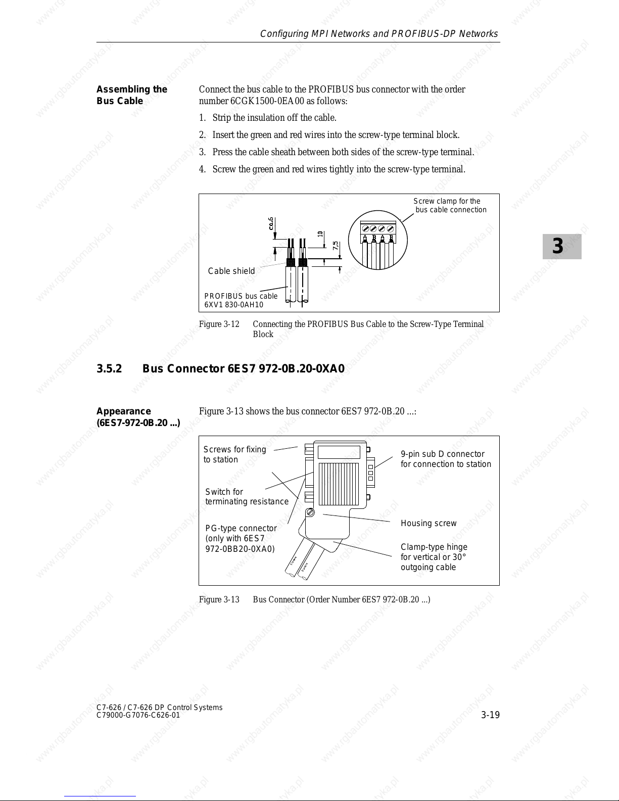
3
3-19
C7-626 / C7-626 DP Control Systems
C79000-G7076-C626-01
Connect the bus cable to the PROFIBUS bus connector with the order
number 6CGK1500-0EA00 as follows:
1. Strip the insulation off the cable.
2. Insert the green and red wires into the screw-type terminal block.
3. Press the cable sheath between both sides of the screw-type terminal.
4. Screw the green and red wires tightly into the screw-type terminal.
Cable shield
Screw clamp for the
bus cable connection
PROFIBUS bus cable
6XV1 830-0AH10
Figure 3-12 Connecting the PROFIBUS Bus Cable to the Screw-Type Terminal
Block
3.5.2 Bus Connector 6ES7 972-0B.20-0XA0
Figure 3-13 shows the bus connector 6ES7 972-0B.20 ...:
Screws for fixing
to station
PG-type connector
(only with 6ES7
972-0BB20-0XA0)
9-pin sub D connector
for connection to station
Housing screw
Switch for
terminating resistance
Clamp-type hinge
for vertical or 30°
outgoing cable
Figure 3-13 Bus Connector (Order Number 6ES7 972-0B.20 ...)
Assembling the
Bus Cable
Appearance
(6ES7-972-0B.20 ...)
Configuring MPI Networks and PROFIBUS-DP Networks
Page 66
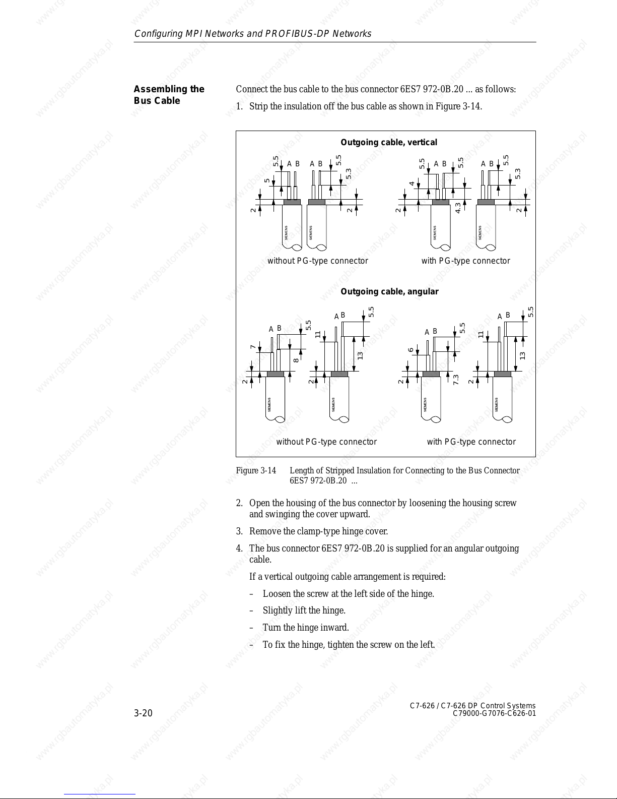
3
3-20
C7-626 / C7-626 DP Control Systems
C79000-G7076-C626-01
Connect the bus cable to the bus connector 6ES7 972-0B.20 ... as follows:
1. Strip the insulation off the bus cable as shown in Figure 3-14.
5.5
11
13
2
A
B
5.5
6
7.3
2
A
B
5.5
5.5
4
4.3
2
AB
5.5
5.3
2
AB
with PG-type connector
5.5
5
2
AB
5.5
5.3
2
AB
5.5
7
8
2
A
B
with PG-type connector
5.5
11
13
2
A
B
Outgoing cable, vertical
without PG-type connector
Outgoing cable, angular
without PG-type connector
Figure 3-14 Length of Stripped Insulation for Connecting to the Bus Connector
6ES7 972-0B.20 ...
2. Open the housing of the bus connector by loosening the housing screw
and swinging the cover upward.
3. Remove the clamp-type hinge cover.
4. The bus connector 6ES7 972-0B.20 is supplied for an angular outgoing
cable.
If a vertical outgoing cable arrangement is required:
– Loosen the screw at the left side of the hinge.
– Slightly lift the hinge.
– Turn the hinge inward.
– To fix the hinge, tighten the screw on the left.
Assembling the
Bus Cable
Configuring MPI Networks and PROFIBUS-DP Networks
Page 67
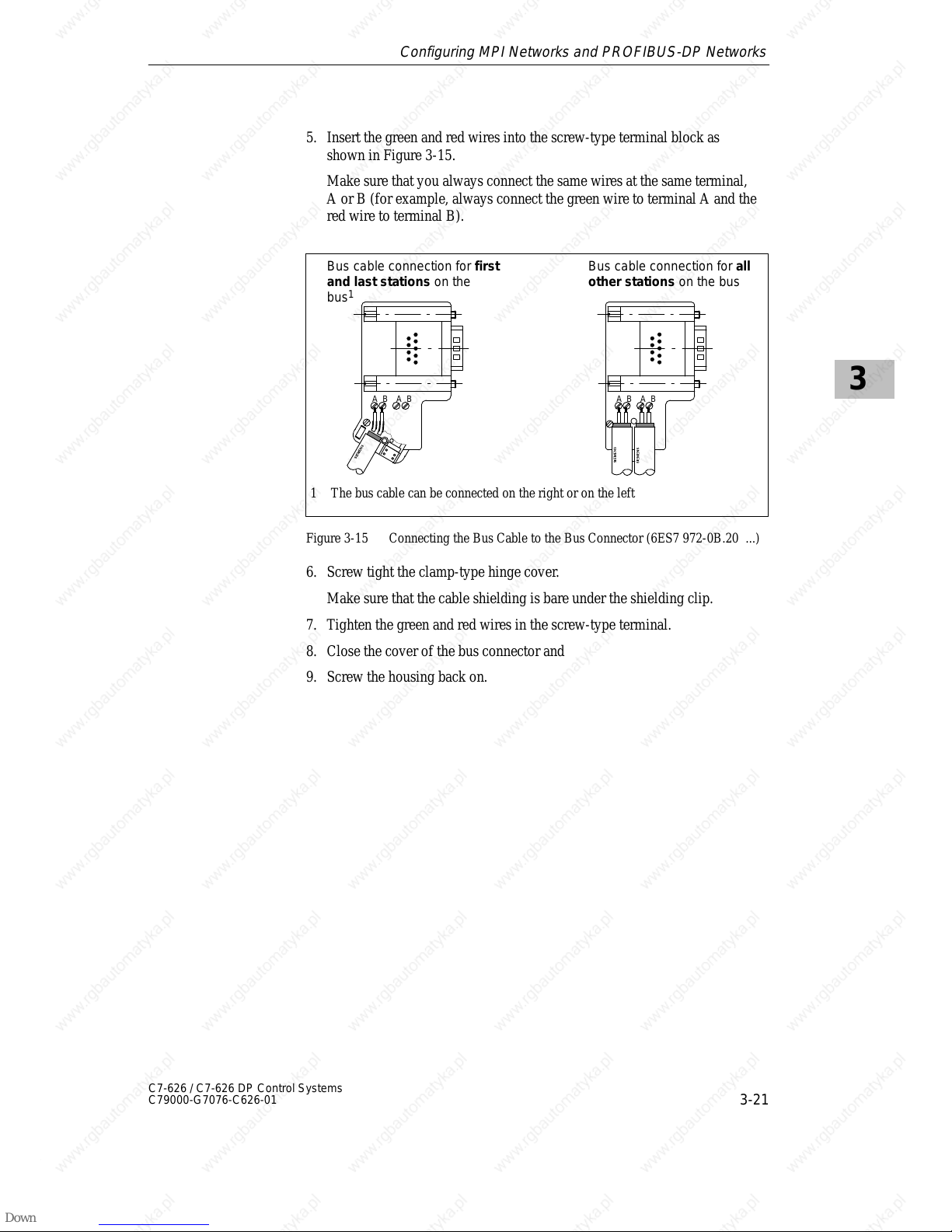
3
3-21
C7-626 / C7-626 DP Control Systems
C79000-G7076-C626-01
5. Insert the green and red wires into the screw-type terminal block as
shown in Figure 3-15.
Make sure that you always connect the same wires at the same terminal,
A or B (for example, always connect the green wire to terminal A and the
red wire to terminal B).
Bus cable connection for first
and last stations on the
bus
1
Bus cable connection for all
other stations on the bus
1 The bus cable can be connected on the right or on the left
A B A B A B A B
Figure 3-15 Connecting the Bus Cable to the Bus Connector (6ES7 972-0B.20 ...)
6. Screw tight the clamp-type hinge cover.
Make sure that the cable shielding is bare under the shielding clip.
7. Tighten the green and red wires in the screw-type terminal.
8. Close the cover of the bus connector and
9. Screw the housing back on.
Configuring MPI Networks and PROFIBUS-DP Networks
Page 68
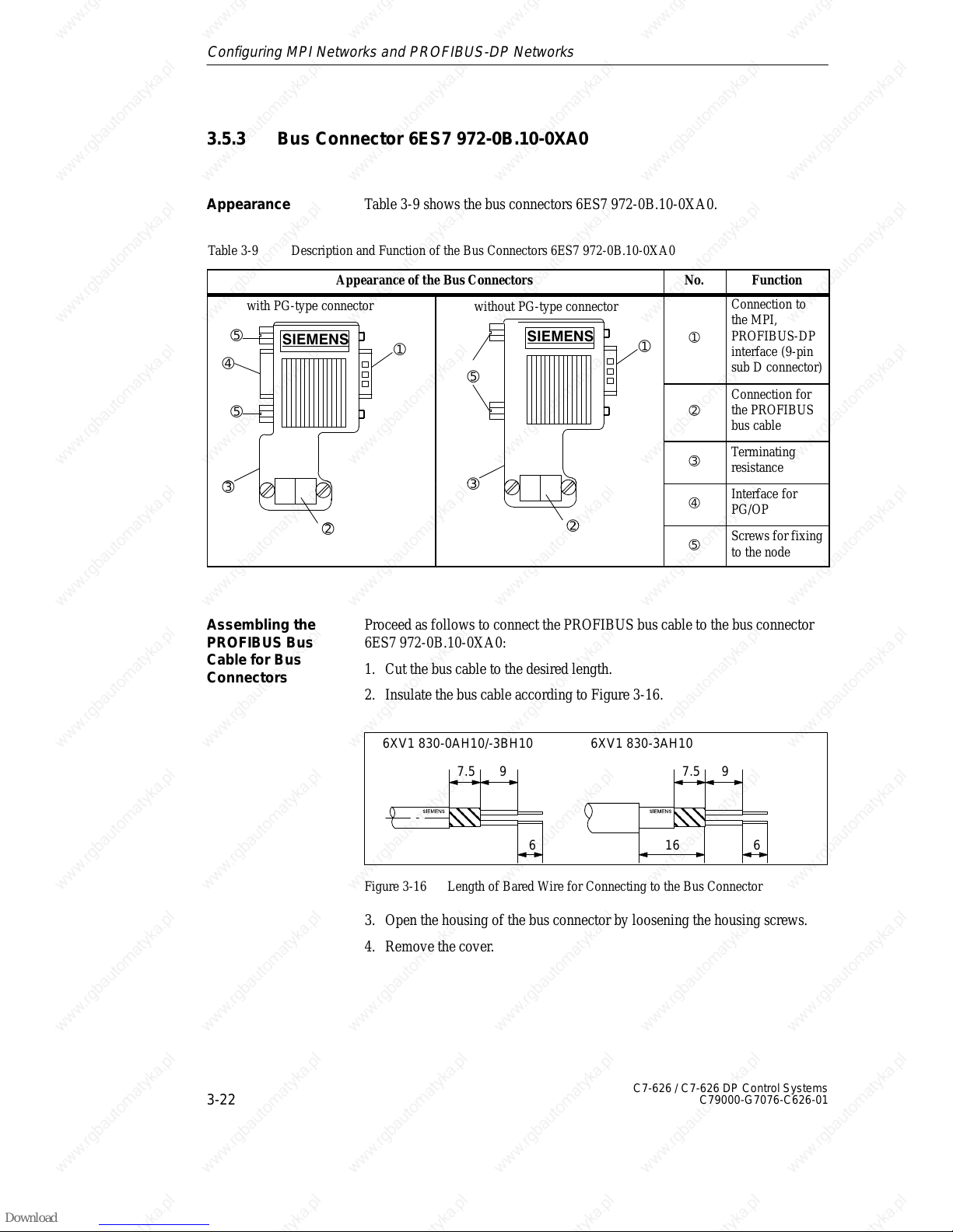
3
3-22
C7-626 / C7-626 DP Control Systems
C79000-G7076-C626-01
3.5.3 Bus Connector 6ES7 972-0B.10-0XA0
Table 3-9 shows the bus connectors 6ES7 972-0B.10-0XA0.
Table 3-9 Description and Function of the Bus Connectors 6ES7 972-0B.10-0XA0
Appearance of the Bus Connectors No. Function
with PG-type connector
➀
➃
➄
without PG-type connector
➀
➄
➀
Connection to
the MPI,
PROFIBUS-DP
interface (9-pin
sub D connector)
➄
➄
➁
Connection for
the PROFIBUS
bus cable
➂
Terminating
resistance
➂
➂
➃
Interface for
PG/OP
➁
➁
➄
Screws for fixing
to the node
Proceed as follows to connect the PROFIBUS bus cable to the bus connector
6ES7 972-0B.10-0XA0:
1. Cut the bus cable to the desired length.
2. Insulate the bus cable according to Figure 3-16.
7.5 9
6
7.5 9
6
6XV1 830-0AH10/-3BH10 6XV1 830-3AH10
16
Figure 3-16 Length of Bared Wire for Connecting to the Bus Connector
3. Open the housing of the bus connector by loosening the housing screws.
4. Remove the cover.
Appearance
Assembling the
PROFIBUS Bus
Cable for Bus
Connectors
Configuring MPI Networks and PROFIBUS-DP Networks
Page 69
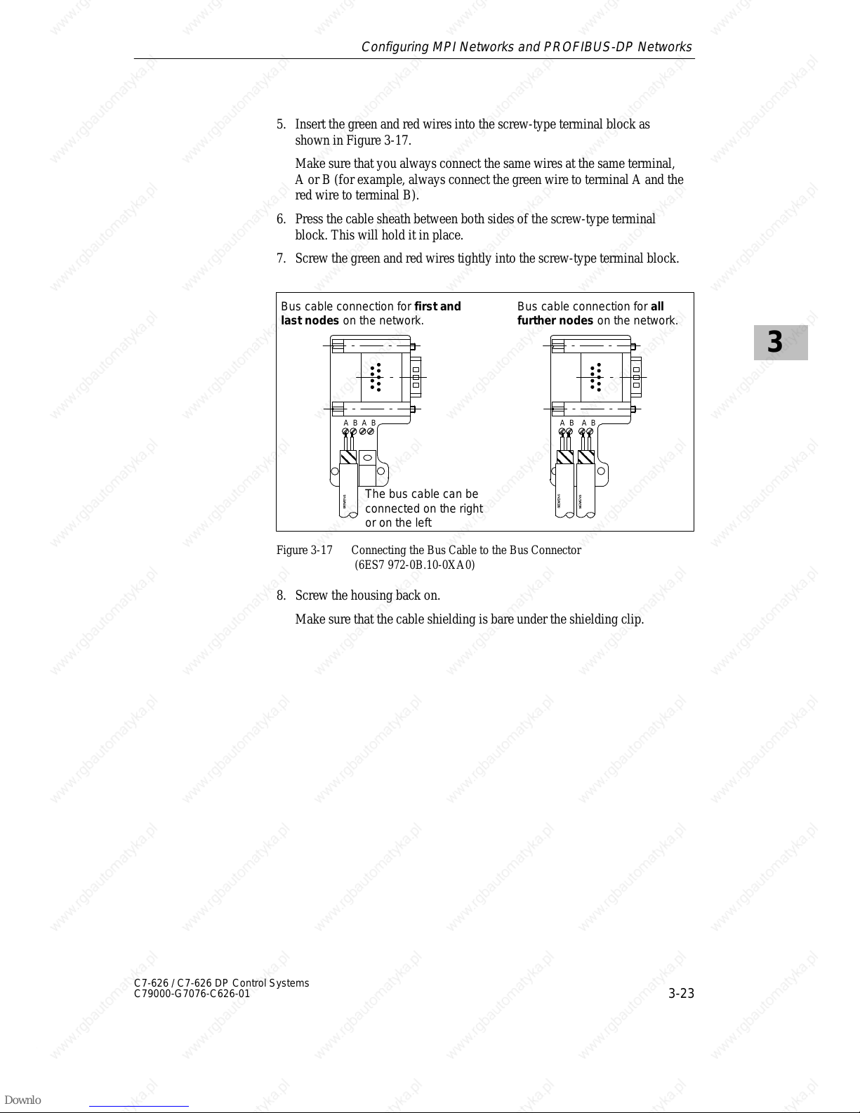
3
3-23
C7-626 / C7-626 DP Control Systems
C79000-G7076-C626-01
5. Insert the green and red wires into the screw-type terminal block as
shown in Figure 3-17.
Make sure that you always connect the same wires at the same terminal,
A or B (for example, always connect the green wire to terminal A and the
red wire to terminal B).
6. Press the cable sheath between both sides of the screw-type terminal
block. This will hold it in place.
7. Screw the green and red wires tightly into the screw-type terminal block.
A B A B
A B A B
Bus cable connection for first and
last nodes on the network.
Bus cable connection for all
further nodes on the network.
The bus cable can be
connected on the right
or on the left
Figure 3-17 Connecting the Bus Cable to the Bus Connector
(6ES7 972-0B.10-0XA0)
8. Screw the housing back on.
Make sure that the cable shielding is bare under the shielding clip.
Configuring MPI Networks and PROFIBUS-DP Networks
Page 70
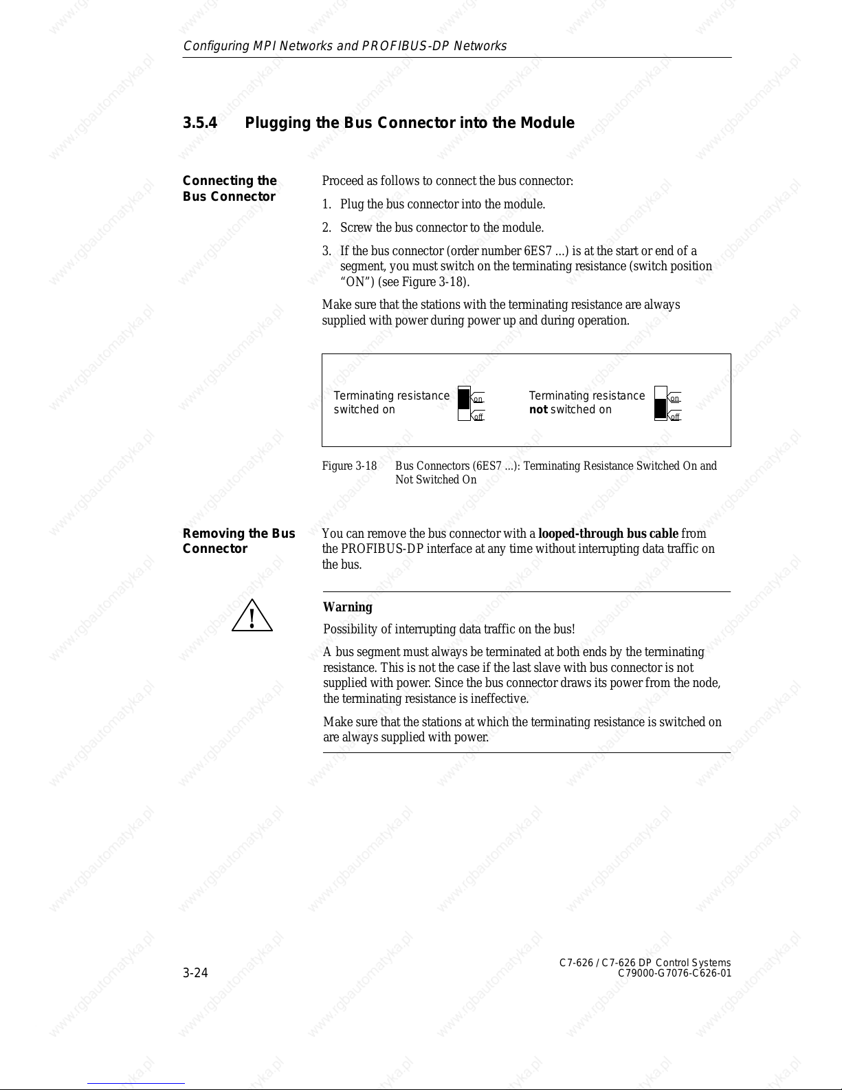
3
3-24
C7-626 / C7-626 DP Control Systems
C79000-G7076-C626-01
3.5.4 Plugging the Bus Connector into the Module
Proceed as follows to connect the bus connector:
1. Plug the bus connector into the module.
2. Screw the bus connector to the module.
3. If the bus connector (order number 6ES7 ...) is at the start or end of a
segment, you must switch on the terminating resistance (switch position
“ON”) (see Figure 3-18).
Make sure that the stations with the terminating resistance are always
supplied with power during power up and during operation.
Terminating resistance
switched on
Terminating resistance
not switched on
on
off
on
off
Figure 3-18 Bus Connectors (6ES7 ...): Terminating Resistance Switched On and
Not Switched On
You can remove the bus connector with a looped-through bus cable from
the PROFIBUS-DP interface at any time without interrupting data traffic on
the bus.
!
Warning
Possibility of interrupting data traffic on the bus!
A bus segment must always be terminated at both ends by the terminating
resistance. This is not the case if the last slave with bus connector is not
supplied with power. Since the bus connector draws its power from the node,
the terminating resistance is ineffective.
Make sure that the stations at which the terminating resistance is switched on
are always supplied with power.
Connecting the
Bus Connector
Removing the Bus
Connector
Configuring MPI Networks and PROFIBUS-DP Networks
Page 71
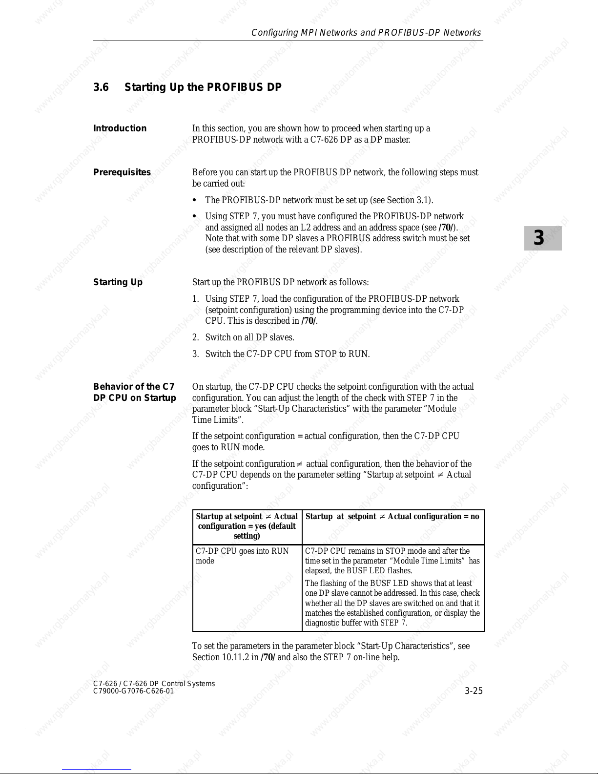
3
3-25
C7-626 / C7-626 DP Control Systems
C79000-G7076-C626-01
3.6 Starting Up the PROFIBUS DP
In this section, you are shown how to proceed when starting up a
PROFIBUS-DP network with a C7-626 DP as a DP master.
Before you can start up the PROFIBUS DP network, the following steps must
be carried out:
S The PROFIBUS-DP network must be set up (see Section 3.1).
S Using STEP 7, you must have configured the PROFIBUS-DP network
and assigned all nodes an L2 address and an address space (see /70/).
Note that with some DP slaves a PROFIBUS address switch must be set
(see description of the relevant DP slaves).
Start up the PROFIBUS DP network as follows:
1. Using STEP 7, load the configuration of the PROFIBUS-DP network
(setpoint configuration) using the programming device into the C7-DP
CPU. This is described in /70/.
2. Switch on all DP slaves.
3. Switch the C7-DP CPU from STOP to RUN.
On startup, the C7-DP CPU checks the setpoint configuration with the actual
configuration. You can adjust the length of the check with STEP 7 in the
parameter block “Start-Up Characteristics” with the parameter “Module
Time Limits”.
If the setpoint configuration = actual configuration, then the C7-DP CPU
goes to RUN mode.
If the setpoint configuration actual configuration, then the behavior of the
C7-DP CPU depends on the parameter setting “Startup at setpoint Actual
configuration”:
Startup at setpoint Actual
configuration = yes (default
setting)
Startup at setpoint Actual configuration = no
C7-DP CPU goes into RUN
mode
C7-DP CPU remains in STOP mode and after the
time set in the parameter “Module Time Limits” has
elapsed, the BUSF LED flashes.
The flashing of the BUSF LED shows that at least
one DP slave cannot be addressed. In this case, check
whether all the DP slaves are switched on and that it
matches the established configuration, or display the
diagnostic buffer with STEP 7.
To set the parameters in the parameter block “Start-Up Characteristics”, see
Section 10.11.2 in /70/ and also the STEP 7 on-line help.
Introduction
Prerequisites
Starting Up
Behavior of the C7
DP CPU on Startup
Configuring MPI Networks and PROFIBUS-DP Networks
Page 72

3
3-26
C7-626 / C7-626 DP Control Systems
C79000-G7076-C626-01
Configuring MPI Networks and PROFIBUS-DP Networks
Page 73
4-1
C7-626 / C7-626 DP Control Systems
C79000-G7076-C626-01
Connecting a Programming Device /
PC to a C7
In Section You Will Find On Page
4.1 Connecting a Programming Device/PC to a C7 4-2
4.2 Connecting a Programming Device/PC to
Several Nodes
4-3
Summary of
Sections
4
Page 74
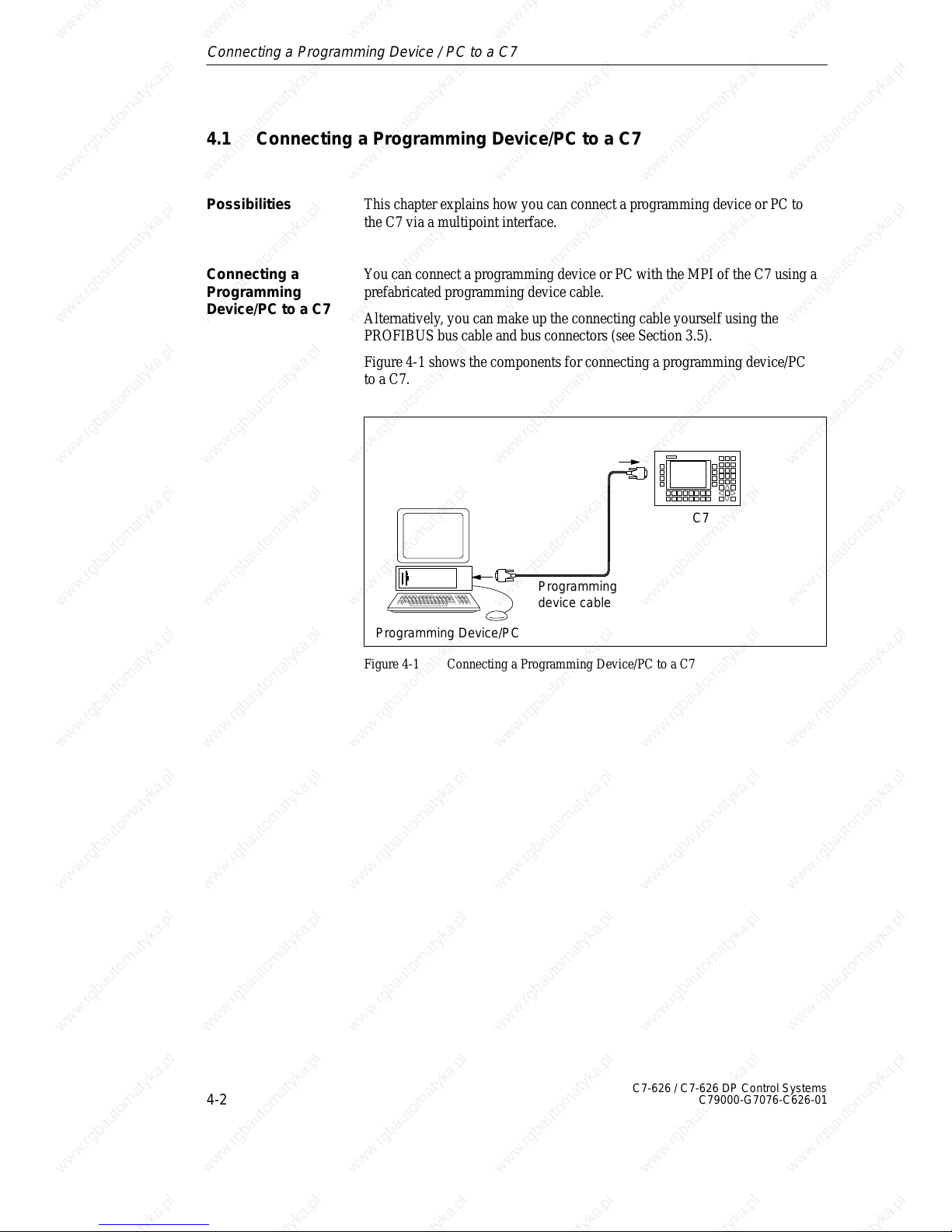
4
4-2
C7-626 / C7-626 DP Control Systems
C79000-G7076-C626-01
4.1 Connecting a Programming Device/PC to a C7
This chapter explains how you can connect a programming device or PC to
the C7 via a multipoint interface.
You can connect a programming device or PC with the MPI of the C7 using a
prefabricated programming device cable.
Alternatively , you can make up the connecting cable yourself using the
PROFIBUS bus cable and bus connectors (see Section 3.5).
Figure 4-1 shows the components for connecting a programming device/PC
to a C7.
Programming
device cable
Programming Device/PC
C7
Figure 4-1 Connecting a Programming Device/PC to a C7
Possibilities
Connecting a
Programming
Device/PC to a C7
Connecting a Programming Device / PC to a C7
Page 75
4
4-3
C7-626 / C7-626 DP Control Systems
C79000-G7076-C626-01
4.2 Connecting a Programming Device/PC to Several Nodes
This chapter shows you how to connect a programming device or PC to
several networked nodes via the MPI.
When you connect a programming device/PC to several nodes, you must
differentiate between two installation variants:
S Fixed installation of the programming device/PC in the MPI network
S Programming device/PC connected for startup and maintenance purposes.
Depending on this, you connect the programming device/PC with the other
nodes as follows (see also Section 3.2):
Installation Variant
Connection
Fixed installation of the
programming device/PC in the MPI
network
The programming device/PC is
linked directly into the MPI network
Programming device/PC connected
for startup and maintenance
purposes
The programming device/PC is
connected to one node via a spur
line
Possibilities
Two Installation
Variants
Connecting a Programming Device / PC to a C7
Page 76
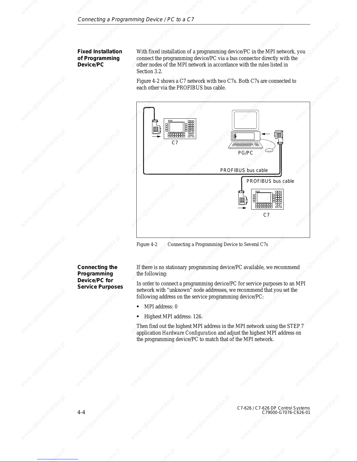
4
4-4
C7-626 / C7-626 DP Control Systems
C79000-G7076-C626-01
With fixed installation of a programming device/PC in the MPI network, you
connect the programming device/PC via a bus connector directly with the
other nodes of the MPI network in accordance with the rules listed in
Section 3.2.
Figure 4-2 shows a C7 network with two C7s. Both C7s are connected to
each other via the PROFIBUS bus cable.
PROFIBUS bus cable
C7
C7
PG/PC
PROFIBUS bus cable
Figure 4-2 Connecting a Programming Device to Several C7s
If there is no stationary programming device/PC available, we recommend
the following:
In order to connect a programming device/PC for service purposes to an MPI
network with “unknown” node addresses, we recommend that you set the
following address on the service programming device/PC:
S MPI address: 0
S Highest MPI address: 126.
Then find out the highest MPI address in the MPI network using the STEP 7
application Hardware Configuration and adjust the highest MPI address on
the programming device/PC to match that of the MPI network.
Fixed Installation
of Programming
Device/PC
Connecting the
Programming
Device/PC for
Service Purposes
Connecting a Programming Device / PC to a C7
Page 77
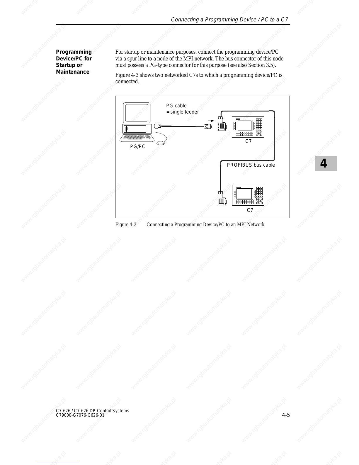
4
4-5
C7-626 / C7-626 DP Control Systems
C79000-G7076-C626-01
For startup or maintenance purposes, connect the programming device/PC
via a spur line to a node of the MPI network. The bus connector of this node
must possess a PG-type connector for this purpose (see also Section 3.5).
Figure 4-3 shows two networked C7s to which a programming device/PC is
connected.
PROFIBUS bus cable
PG cable
= single feeder
C7
PG/PC
C7
Figure 4-3 Connecting a Programming Device/PC to an MPI Network
Programming
Device/PC for
Startup or
Maintenance
Connecting a Programming Device / PC to a C7
Page 78

4
4-6
C7-626 / C7-626 DP Control Systems
C79000-G7076-C626-01
Connecting a Programming Device / PC to a C7
Page 79
5-1
C7-626 / C7-626 DP Control Systems
C79000-G7076-C626-01
C7 Digital Input/Output
In Section You Will Find On Page
5.1 Digital Input Function 5-2
5.2 Digital Output Function 5-4
5.3 Status Bits of the DI/DO 5-7
Summary of
Sections
5
Page 80
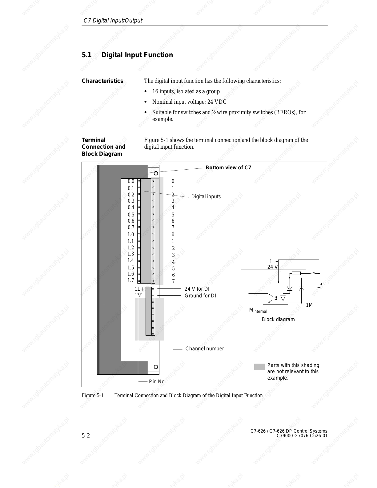
5
5-2
C7-626 / C7-626 DP Control Systems
C79000-G7076-C626-01
5.1 Digital Input Function
The digital input function has the following characteristics:
S 16 inputs, isolated as a group
S Nominal input voltage: 24 VDC
S Suitable for switches and 2-wire proximity switches (BEROs), for
example.
Figure 5-1 shows the terminal connection and the block diagram of the
digital input function.
Channel number
Pin No.
0.0
0.1
0.2
0.3
0.4
0.5
0.6
0.7
Parts with this shading
are not relevant to this
example.
0
1
2
3
4
5
6
7
0
1
2
3
4
5
6
7
Digital inputs
1L+
1M
24 V for DI
Ground for DI
1.0
1.1
1.2
1.3
1.4
1.5
1.6
1.7
Block diagram
24 V
1L+
M
internal
Bottom view of C7
1M
Figure 5-1 Terminal Connection and Block Diagram of the Digital Input Function
Characteristics
Terminal
Connection and
Block Diagram
C7 Digital Input/Output
Page 81
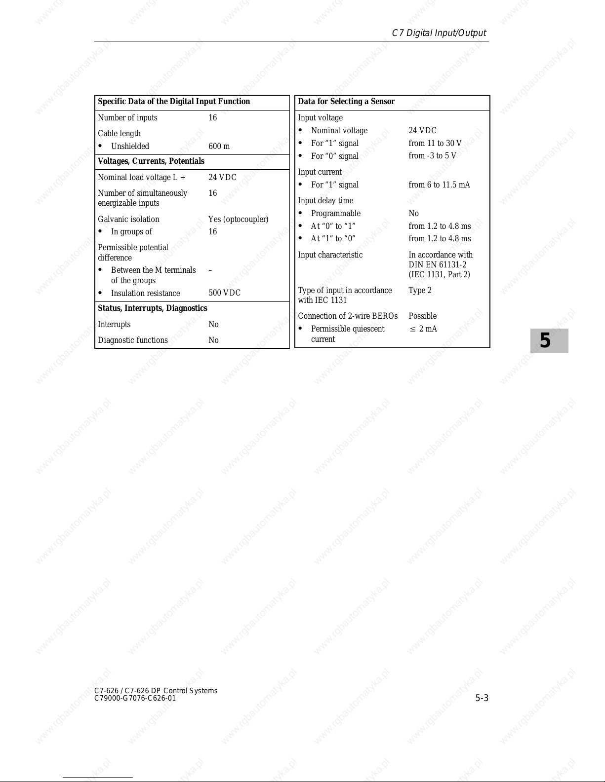
5
5-3
C7-626 / C7-626 DP Control Systems
C79000-G7076-C626-01
Specific Data of the Digital Input Function
Number of inputs 16
Cable length
S Unshielded 600 m
Voltages, Currents, Potentials
Nominal load voltage L + 24 VDC
Number of simultaneously
energizable inputs
16
Galvanic isolation
S In groups of
Yes (optocoupler)
16
Permissible potential
difference
S Between the M terminals
of the groups
S Insulation resistance
–
500 VDC
Status, Interrupts, Diagnostics
Interrupts No
Diagnostic functions No
Data for Selecting a Sensor
Input voltage
S Nominal voltage
S For “1” signal
S For “0” signal
24 VDC
from 11 to 30 V
from -3 to 5 V
Input current
S For “1” signal from 6 to 11.5 mA
Input delay time
S Programmable
S At “0” to “1”
S At “1” to “0”
No
from 1.2 to 4.8 ms
from 1.2 to 4.8 ms
Input characteristic In accordance with
DIN EN 61131-2
(IEC 1131, Part 2)
Type of input in accordance
with IEC 1131
Type 2
Connection of 2-wire BEROs
S Permissible quiescent
current
Possible
2 mA
C7 Digital Input/Output
Page 82
5
5-4
C7-626 / C7-626 DP Control Systems
C79000-G7076-C626-01
5.2 Digital Output Function
The digital output function has the following characteristics:
S 16 outputs, isolated.
S Output current: 0.5 A
S Nominal load voltage: 24 VDC
S Suitable for solenoid valves and d.c. contactors.
The digital outputs may be briefly activated under the following conditions:
S Applying the DI/DO power supply (independently of the 24V/GND
wiring)
S Applying the 24V/GND, if the DI/DO power supply is already wired.
A pulse can be approximately 50 µs within the permissible output voltage
range. You must observe this when using digital outputs in conjunction with
high speed counters.
Characteristics
Special Feature
C7 Digital Input/Output
Page 83
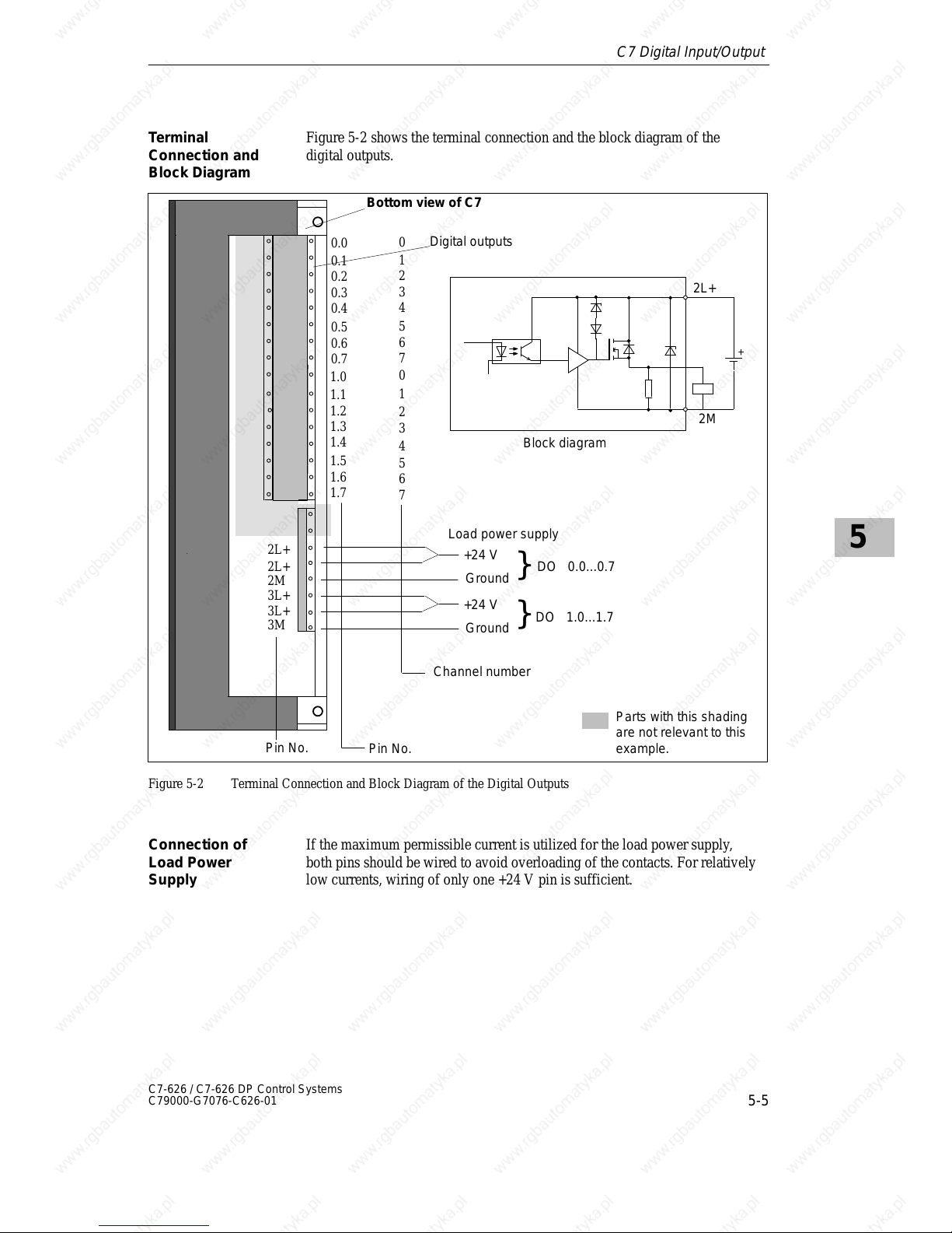
5
5-5
C7-626 / C7-626 DP Control Systems
C79000-G7076-C626-01
Figure 5-2 shows the terminal connection and the block diagram of the
digital outputs.
Channel number
Pin No.
Parts with this shading
are not relevant to this
example.
0
1
2
3
4
5
6
7
0
1
2
3
4
5
6
7
Digital outputs
2L+
2L+
2M
3L+
3L+
3M
Load power supply
Pin No.
0.0
0.1
0.2
0.3
0.4
0.5
0.6
0.7
1.0
1.1
1.2
1.3
1.4
1.5
1.6
1.7
Block diagram
2L+
2M
+24 V
Ground
+24 V
Ground
}
}
DO 0.0...0.7
DO 1.0...1.7
Bottom view of C7
Figure 5-2 Terminal Connection and Block Diagram of the Digital Outputs
If the maximum permissible current is utilized for the load power supply,
both pins should be wired to avoid overloading of the contacts. For relatively
low currents, wiring of only one +24 V pin is sufficient.
T erminal
Connection and
Block Diagram
Connection of
Load Power
Supply
C7 Digital Input/Output
Page 84
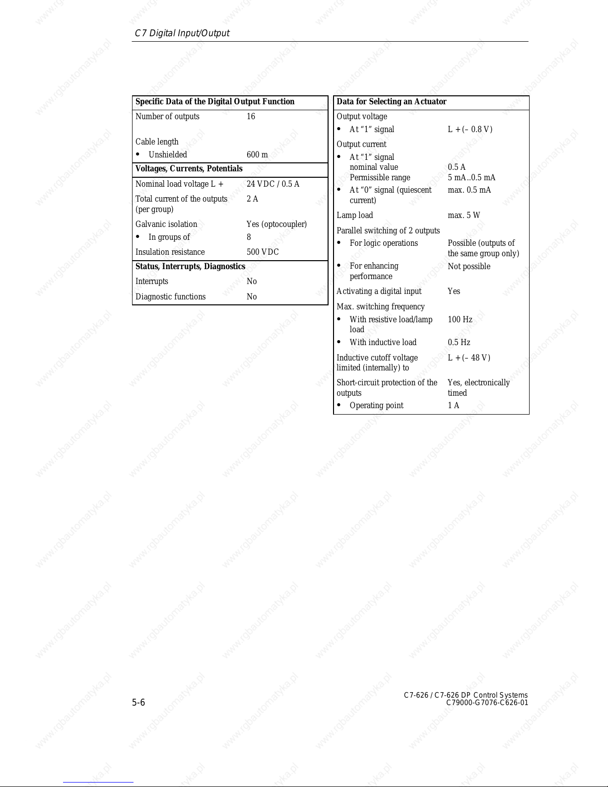
5
5-6
C7-626 / C7-626 DP Control Systems
C79000-G7076-C626-01
Specific Data of the Digital Output Function
Number of outputs 16
Cable length
S Unshielded 600 m
Voltages, Currents, Potentials
Nominal load voltage L + 24 VDC / 0.5 A
Total current of the outputs
(per group)
2 A
Galvanic isolation
S In groups of
Yes (optocoupler)
8
Insulation resistance 500 VDC
Status, Interrupts, Diagnostics
Interrupts No
Diagnostic functions No
Data for Selecting an Actuator
Output voltage
S At “1” signal L + (– 0.8 V)
Output current
S At “1” signal
nominal value
Permissible range
S At “0” signal (quiescent
current)
0.5 A
5 mA..0.5 mA
max. 0.5 mA
Lamp load max. 5 W
Parallel switching of 2 outputs
S For logic operations
S For enhancing
performance
Possible (outputs of
the same group only)
Not possible
Activating a digital input Yes
Max. switching frequency
S With resistive load/lamp
load
S With inductive load
100 Hz
0.5 Hz
Inductive cutoff voltage
limited (internally) to
L + (– 48 V)
Short-circuit protection of the
outputs
S Operating point
Yes, electronically
timed
1 A
C7 Digital Input/Output
Page 85
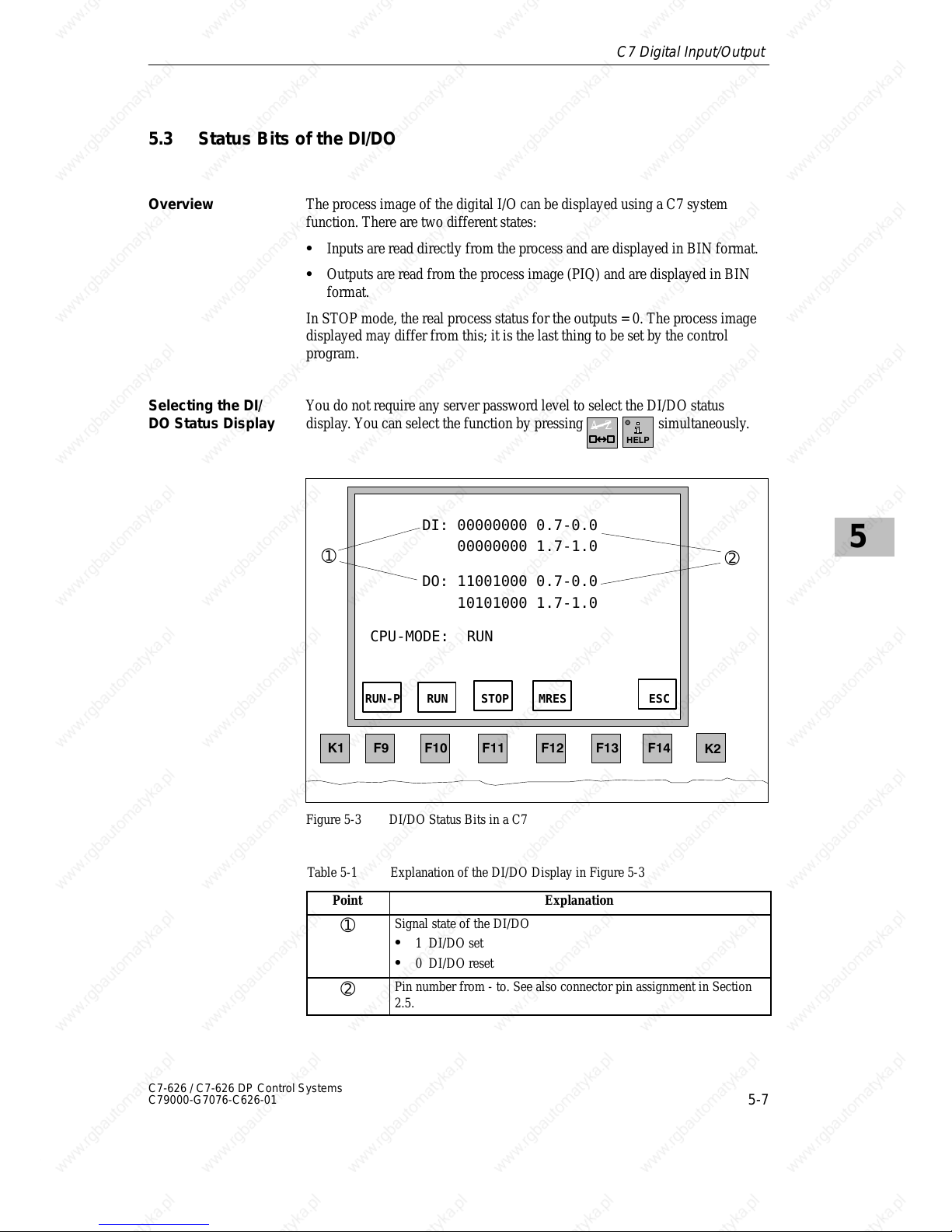
5
5-7
C7-626 / C7-626 DP Control Systems
C79000-G7076-C626-01
5.3 Status Bits of the DI/DO
The process image of the digital I/O can be displayed using a C7 system
function. There are two different states:
S Inputs are read directly from the process and are displayed in BIN format.
S Outputs are read from the process image (PIQ) and are displayed in BIN
format.
In STOP mode, the real process status for the outputs = 0. The process image
displayed may differ from this; it is the last thing to be set by the control
program.
You do not require any server password level to select the DI/DO status
display . You can select the function by pressing
A–Z
simultaneously.
DI: 00000000 0.7-0.0
00000000 1.7-1.0
DO: 11001000 0.7-0.0
10101000 1.7-1.0
CPU-MODE: RUN
RUN-P RUN STOP MRES ESC
➀
➁
Figure 5-3 DI/DO Status Bits in a C7
Table 5-1 Explanation of the DI/DO Display in Figure 5-3
Point
Explanation
➀
Signal state of the DI/DO
S 1 DI/DO set
S 0 DI/DO reset
➁
Pin number from - to. See also connector pin assignment in Section
2.5.
Overview
Selecting the DI/
DO Status Display
C7 Digital Input/Output
Page 86
5
5-8
C7-626 / C7-626 DP Control Systems
C79000-G7076-C626-01
Note
The values of the DI/DO are read and displayed every 500 ms (default
value). Changes which occur between these times are not displayed.
Exit the DI/DO status display by pressing
.Exiting the DI/DO
Status Display
C7 Digital Input/Output
Page 87
6-1
C7-626 / C7-626 DP Control Systems
C79000-G7076-C626-01
C7 Analog Input/Output
In Section You Will Find On Page
6.1 Connecting Transducers to Analog Inputs 6-2
6.1.1 Connecting Voltage and Current Transducers 6-5
6.2 Connecting Loads/Actuators to the Analog Output 6-6
6.3 Analog Input Function 6-9
6.3.1 Characteristics and Technical Specifications of the
Analog Input Module
6-10
6.4 Analog Output Function 6-15
The C7 cannot be installed in an ungrounded configuration.
Summary of
Sections
Ungrounded
Configuration
6
Page 88
6
6-2
C7-626 / C7-626 DP Control Systems
C79000-G7076-C626-01
6.1 Connecting Transducers to Analog Inputs
You can connect various types of transducers to the analog inputs:
S Voltage transducers
S Current transducers
To reduce electrical interference, you should use twisted-pair shielded cables
for the analog signals. The shield of the analog signal cables should be
grounded at both cable ends. If there are potential differences between the
cable ends, an equipotential bonding current can flow over the shield. This
can interfere with the analog signals. In such a case, you should ground the
shield at one end of the cable only.
The analog input is isolated and so there is no electrical connection between
the reference point of the measuring circuit M
ANA
and the M terminal of the
C7 power supply (see Figure 6-1).
A potential difference V
ISO
can occur between the reference point of the
measuring circuit M
ANA
and the M terminal of the C7. Make sure that V
ISO
does not exceed the permissible value. Where it is possible that the
permissible value might be exceeded (see technical specifications), establish
a connection between the M
ANA
terminal and the M terminal of the C7.
A potential difference V
CM
(common mode voltage) may occur between the
measuring line AIx-M of the input channels and the reference point of the
measuring circuit M
ANA
. However, this potential difference must not exceed
the permissible value. Where it is possible that the permissible value for V
CM
might be exceeded, or where you cannot determine the difference in potential
accurately , you must connect AIx-M to M
ANA
. Please observe this also for
the unused inputs.
The abbreviations used in Figures 6-1 to 6-3 have the following meanings:
AIx-X: Measuring line AIx-U or AIx-I
AIx-M: Reference potential of the measuring line
M
ANA
: Reference potential of the analog measuring circuit
M: Ground terminal of the C7
V
CM
: Potential difference between inputs and M
ANA
V
ISO
: Potential difference between M
ANA
and the M terminal of the
C7
Overview
Cables for Analog
Signals
Isolated Analog
Input
Connecting
Transducers to
Analog Inputs
Abbreviations
C7 Analog Input/Output
Page 89
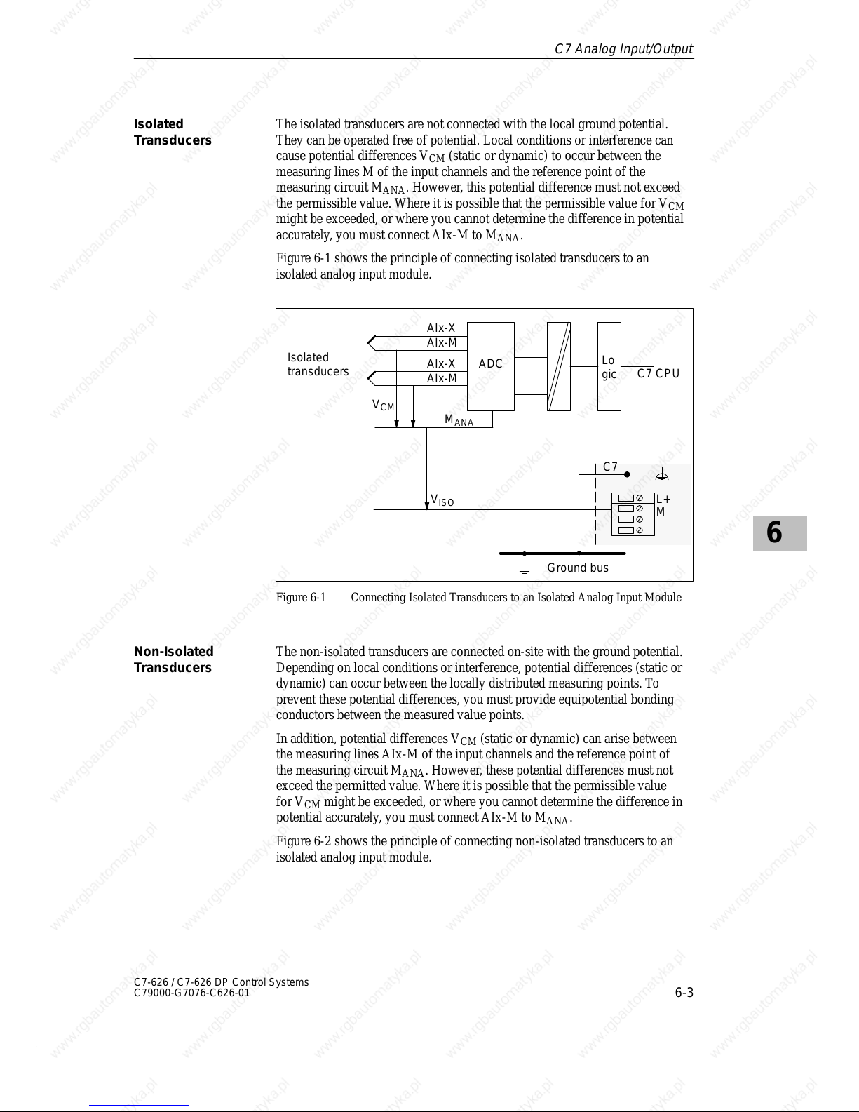
6
6-3
C7-626 / C7-626 DP Control Systems
C79000-G7076-C626-01
The isolated transducers are not connected with the local ground potential.
They can be operated free of potential. Local conditions or interference can
cause potential differences V
CM
(static or dynamic) to occur between the
measuring lines M of the input channels and the reference point of the
measuring circuit M
ANA
. However, this potential difference must not exceed
the permissible value. Where it is possible that the permissible value for V
CM
might be exceeded, or where you cannot determine the difference in potential
accurately , you must connect AIx-M to M
ANA
.
Figure 6-1 shows the principle of connecting isolated transducers to an
isolated analog input module.
Isolated
transducers
AIx-X
M
ANA
C7 CPU
V
CM
ADC
M
V
ISO
Lo
gic
AIx-M
AIx-X
AIx-M
L+
C7
Ground bus
Figure 6-1 Connecting Isolated Transducers to an Isolated Analog Input Module
The non-isolated transducers are connected on-site with the ground potential.
Depending on local conditions or interference, potential differences (static or
dynamic) can occur between the locally distributed measuring points. To
prevent these potential differences, you must provide equipotential bonding
conductors between the measured value points.
In addition, potential differences V
CM
(static or dynamic) can arise between
the measuring lines AIx-M of the input channels and the reference point of
the measuring circuit M
ANA
. However, these potential differences must not
exceed the permitted value. Where it is possible that the permissible value
for V
CM
might be exceeded, or where you cannot determine the difference in
potential accurately , you must connect AIx-M to M
ANA
.
Figure 6-2 shows the principle of connecting non-isolated transducers to an
isolated analog input module.
Isolated
Transducers
Non-Isolated
Transducers
C7 Analog Input/Output
Page 90
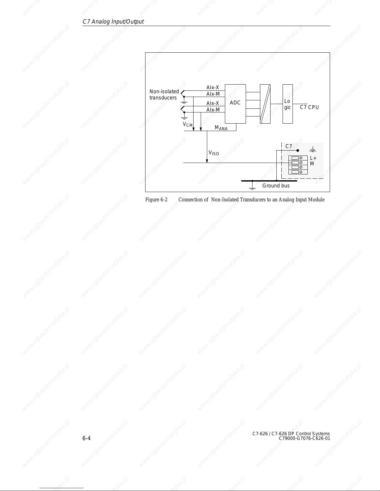
6
6-4
C7-626 / C7-626 DP Control Systems
C79000-G7076-C626-01
Non-isolated
transducers
M
ANA
C7 CPU
V
CM
ADC
Ground bus
V
ISO
Lo
gic
AIx-X
AIx-M
AIx-X
AIx-M
C7
M
L+
Figure 6-2 Connection of Non-Isolated Transducers to an Analog Input Module
C7 Analog Input/Output
Page 91
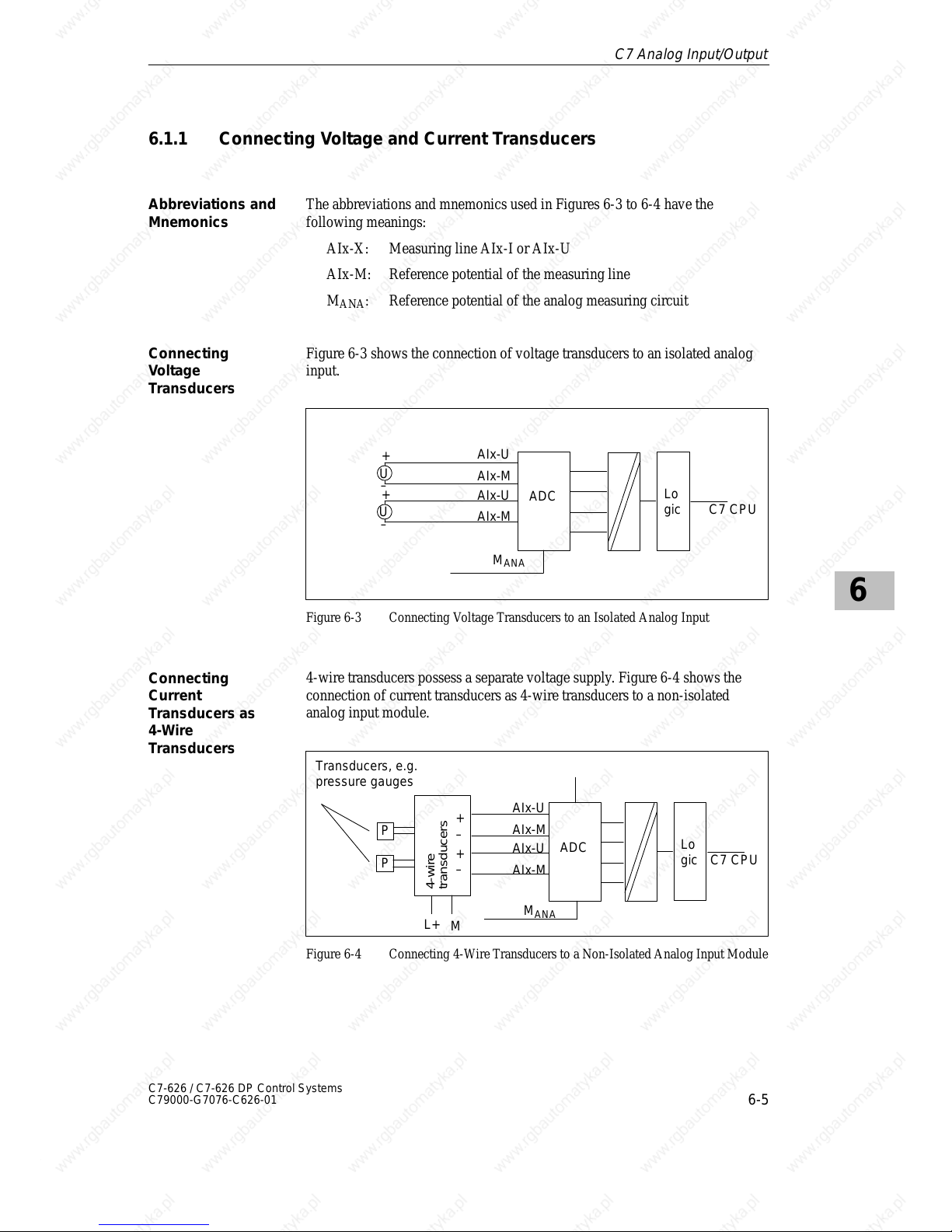
6
6-5
C7-626 / C7-626 DP Control Systems
C79000-G7076-C626-01
6.1.1 Connecting Voltage and Current Transducers
The abbreviations and mnemonics used in Figures 6-3 to 6-4 have the
following meanings:
AIx-X: Measuring line AIx-I or AIx-U
AIx-M: Reference potential of the measuring line
M
ANA
: Reference potential of the analog measuring circuit
Figure 6-3 shows the connection of voltage transducers to an isolated analog
input.
M
ANA
ADC
+
–
U
+
–
U
C7 CPU
Lo
gic
AIx-U
AIx-M
AIx-U
AIx-M
Figure 6-3 Connecting Voltage Transducers to an Isolated Analog Input
4-wire transducers possess a separate voltage supply. Figure 6-4 shows the
connection of current transducers as 4-wire transducers to a non-isolated
analog input module.
M
ANA
ADC
P
P
Transducers, e.g.
pressure gauges
transducers
4-wire
+
–
+
–
L+
M
C7 CPU
Lo
gic
AIx-U
AIx-M
AIx-U
AIx-M
Figure 6-4 Connecting 4-Wire Transducers to a Non-Isolated Analog Input Module
Abbreviations and
Mnemonics
Connecting
Voltage
Transducers
Connecting
Current
Transducers as
4-Wire
Transducers
C7 Analog Input/Output
Page 92
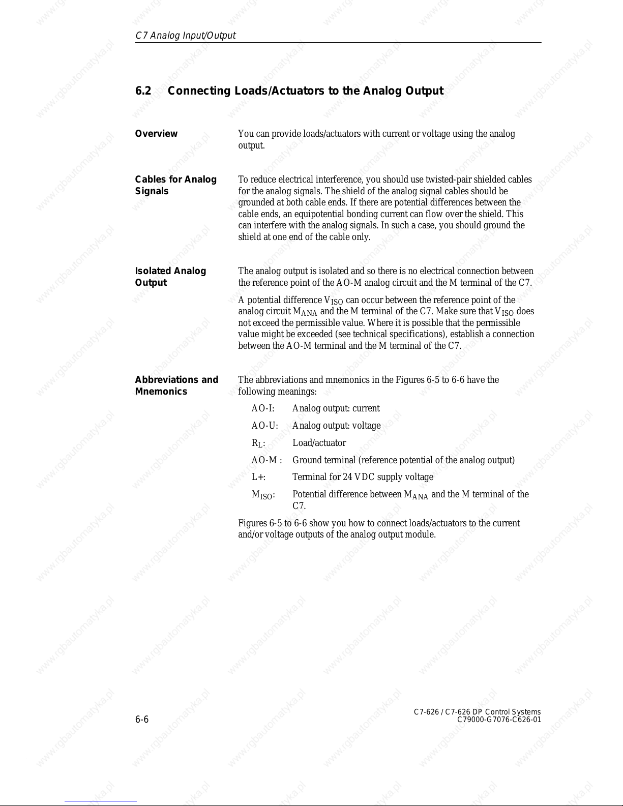
6
6-6
C7-626 / C7-626 DP Control Systems
C79000-G7076-C626-01
6.2 Connecting Loads/Actuators to the Analog Output
You can provide loads/actuators with current or voltage using the analog
output.
To reduce electrical interference, you should use twisted-pair shielded cables
for the analog signals. The shield of the analog signal cables should be
grounded at both cable ends. If there are potential differences between the
cable ends, an equipotential bonding current can flow over the shield. This
can interfere with the analog signals. In such a case, you should ground the
shield at one end of the cable only.
The analog output is isolated and so there is no electrical connection between
the reference point of the AO-M analog circuit and the M terminal of the C7.
A potential difference V
ISO
can occur between the reference point of the
analog circuit M
ANA
and the M terminal of the C7. Make sure that V
ISO
does
not exceed the permissible value. Where it is possible that the permissible
value might be exceeded (see technical specifications), establish a connection
between the AO-M terminal and the M terminal of the C7.
The abbreviations and mnemonics in the Figures 6-5 to 6-6 have the
following meanings:
AO-I: Analog output: current
AO-U: Analog output: voltage
R
L
: Load/actuator
AO-M : Ground terminal (reference potential of the analog output)
L+: Terminal for 24 VDC supply voltage
M
ISO
: Potential difference between M
ANA
and the M terminal of the
C7.
Figures 6-5 to 6-6 show you how to connect loads/actuators to the current
and/or voltage outputs of the analog output module.
Overview
Cables for Analog
Signals
Isolated Analog
Output
Abbreviations and
Mnemonics
C7 Analog Input/Output
Page 93
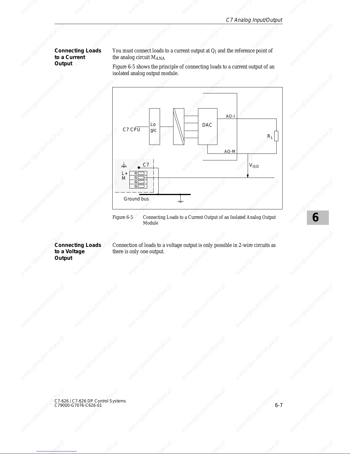
6
6-7
C7-626 / C7-626 DP Control Systems
C79000-G7076-C626-01
You must connect loads to a current output at QI and the reference point of
the analog circuit M
ANA
Figure 6-5 shows the principle of connecting loads to a current output of an
isolated analog output module.
C7 CPU
DAC
R
L
AO-I
Ground bus
V
ISO
Lo
gic
C7
M
L+
AO-M
Figure 6-5 Connecting Loads to a Current Output of an Isolated Analog Output
Module
Connection of loads to a voltage output is only possible in 2-wire circuits as
there is only one output.
Connecting Loads
to a Current
Output
Connecting Loads
to a Voltage
Output
C7 Analog Input/Output
Page 94
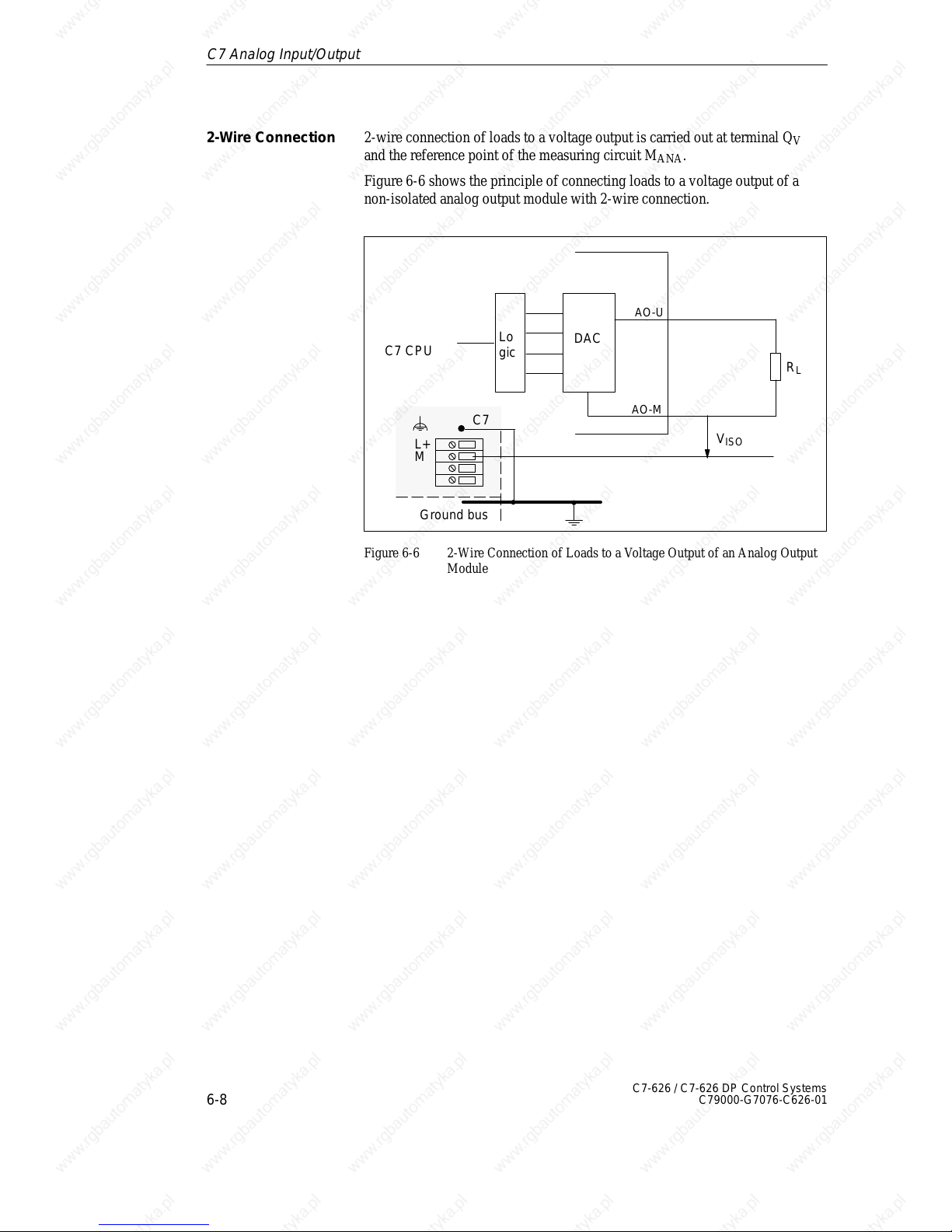
6
6-8
C7-626 / C7-626 DP Control Systems
C79000-G7076-C626-01
2-wire connection of loads to a voltage output is carried out at terminal Q
V
and the reference point of the measuring circuit M
ANA
.
Figure 6-6 shows the principle of connecting loads to a voltage output of a
non-isolated analog output module with 2-wire connection.
C7 CPU
DAC
Ground bus
Lo
gic
R
L
AO-U
C7
M
L+
V
ISO
AO-M
Figure 6-6 2-Wire Connection of Loads to a Voltage Output of an Analog Output
Module
2-Wire Connection
C7 Analog Input/Output
Page 95
6
6-9
C7-626 / C7-626 DP Control Systems
C79000-G7076-C626-01
6.3 Analog Input Function
This section contains
S The characteristics of the analog input module
S The technical specifications of the analog input module
You will learn
S How to start up the analog input module
S The measuring ranges provided by the analog input module
S The parameters you can use to influence the characteristics of the analog
input module.
The following measurement types are available on the analog input module:
S Voltage measurement
S Current measurement
The measuring ranges are:
S Voltage: 10 V
S Current: 20 mA, 4 to 20 mA
For the current range 4 to 20 mA, a current of < 1.6 mA is interpreted per
software as a wire break (see Volume 2, Section 5.2).
Measuring ranges for current measurement with 4-wire transducers:
S 20 mA
S 4 to 20 mA
Overview
Available
Measurement
T ypes
Measuring Ranges
Wire Break Check
Measuring Ranges
for 4-Wire
Transducers
C7 Analog Input/Output
Page 96
6
6-10
C7-626 / C7-626 DP Control Systems
C79000-G7076-C626-01
6.3.1 Characteristics and Technical Specifications of the Analog Input
Module
The analog input module has the following characteristics:
S 4 inputs
S Measured value resolution
– 12 bits including sign
S Measurement type selectable:
– Voltage
– Current
S Choice of measuring range per input
S Diagnostics which can be assigned parameters
S An interrupt which can be assigned parameters
S An interrupt cycle which can be assigned parameters
S Isolated
Characteristics
C7 Analog Input/Output
Page 97
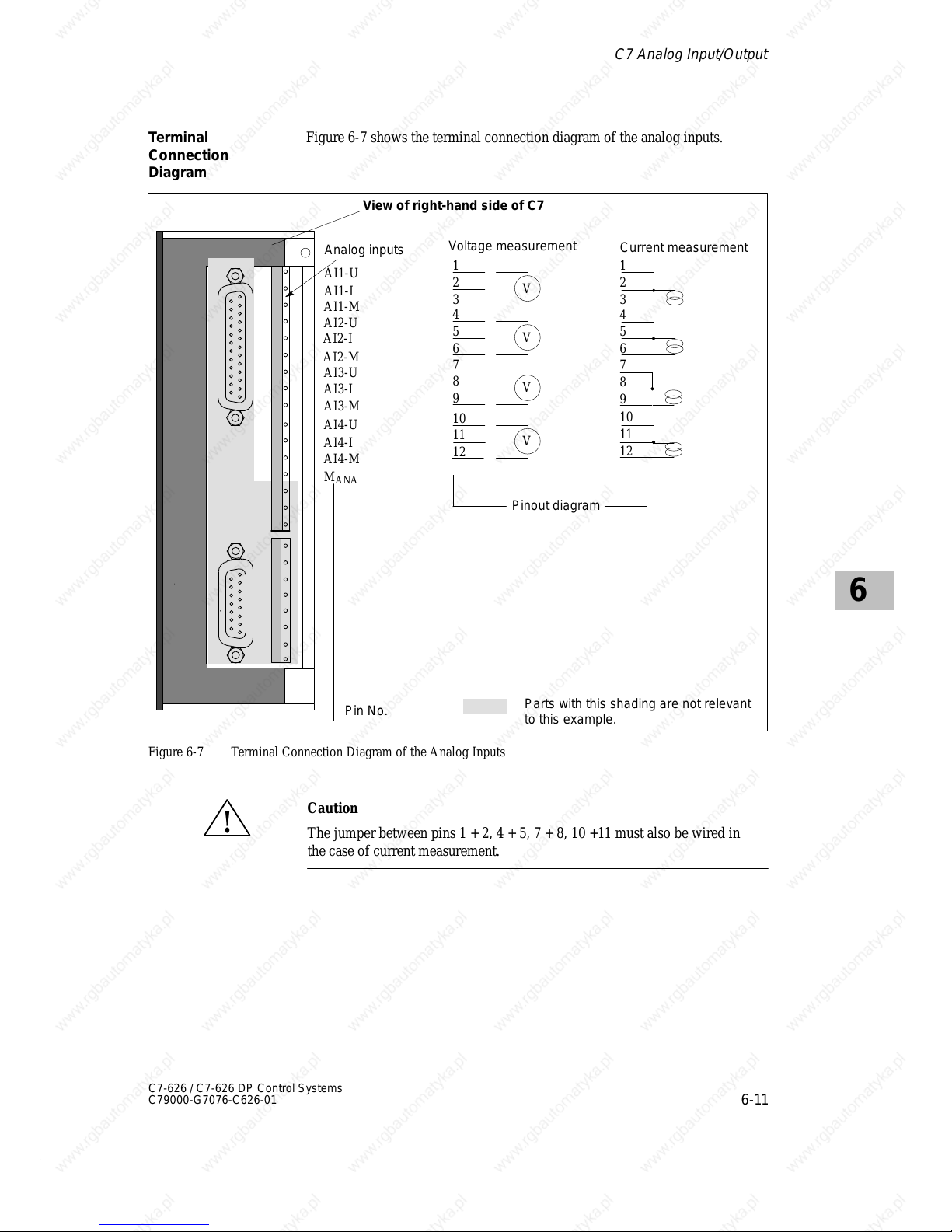
6
6-11
C7-626 / C7-626 DP Control Systems
C79000-G7076-C626-01
Figure 6-7 shows the terminal connection diagram of the analog inputs.
Pinout diagram
Voltage measurement
Analog inputs
Pin No.
AI1-U
AI1-I
AI1-M
AI2-U
AI2-I
AI2-M
AI3-U
AI3-I
AI3-M
AI4-U
AI4-I
2
1
3
V
5
4
6
V
8
7
9
V
11
10
12
V
Current measurement
2
1
3
5
4
6
8
7
9
11
10
12
AI4-M
M
ANA
Parts with this shading are not relevant
to this example.
View of right-hand side of C7
Figure 6-7 Terminal Connection Diagram of the Analog Inputs
!
Caution
The jumper between pins 1 + 2, 4 + 5, 7 + 8, 10 +11 must also be wired in
the case of current measurement.
T erminal
Connection
Diagram
C7 Analog Input/Output
Page 98
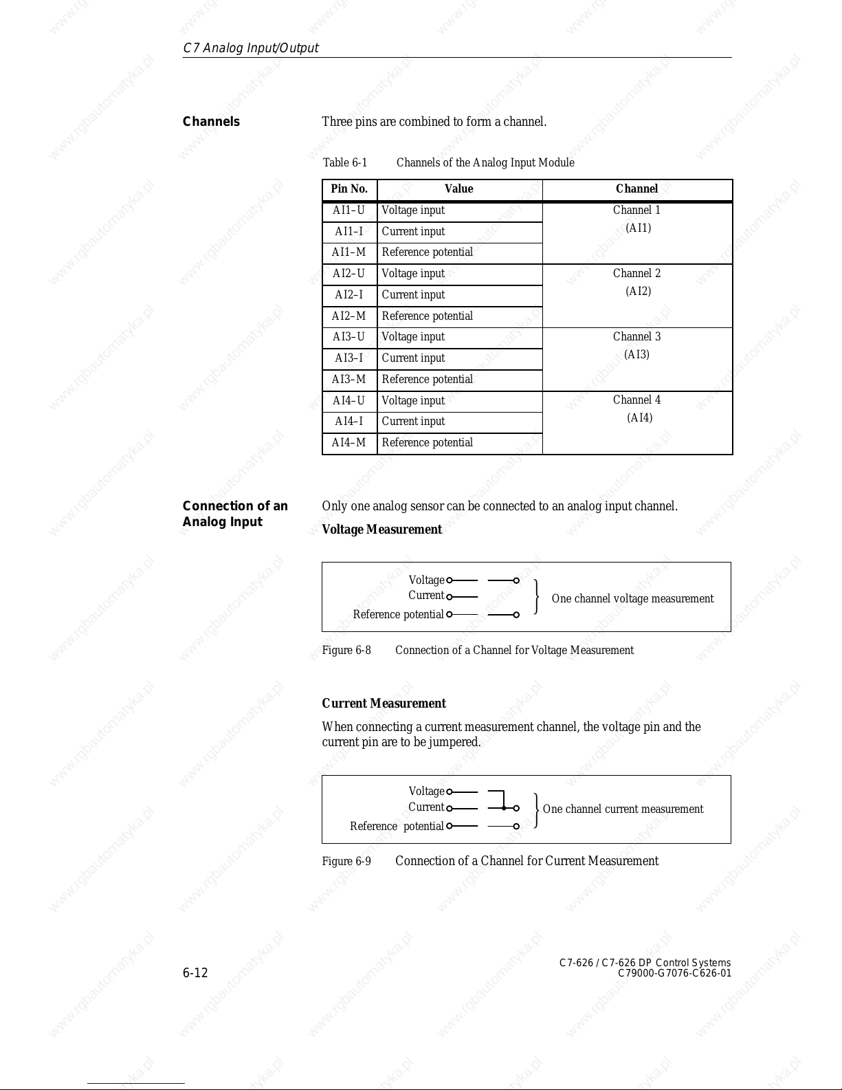
6
6-12
C7-626 / C7-626 DP Control Systems
C79000-G7076-C626-01
Three pins are combined to form a channel.
Table 6-1 Channels of the Analog Input Module
Pin No. Value Channel
AI1–U Voltage input
Channel 1
AI1–I Current input
(AI1)
AI1–M Reference potential
AI2–U Voltage input
Channel 2
AI2–I Current input
(AI2)
AI2–M Reference potential
AI3–U Voltage input
Channel 3
AI3–I Current input
(AI3)
AI3–M Reference potential
AI4–U Voltage input
Channel 4
AI4–I Current input
(AI4)
AI4–M Reference potential
Only one analog sensor can be connected to an analog input channel.
Voltage Measurement
Current
Voltage
Reference potential
One channel voltage measurement
Figure 6-8 Connection of a Channel for Voltage Measurement
Current Measurement
When connecting a current measurement channel, the voltage pin and the
current pin are to be jumpered.
Current
Voltage
Reference potential
One channel current measurement
Figure 6-9 Connection of a Channel for Current Measurement
Channels
Connection of an
Analog Input
C7 Analog Input/Output
Page 99
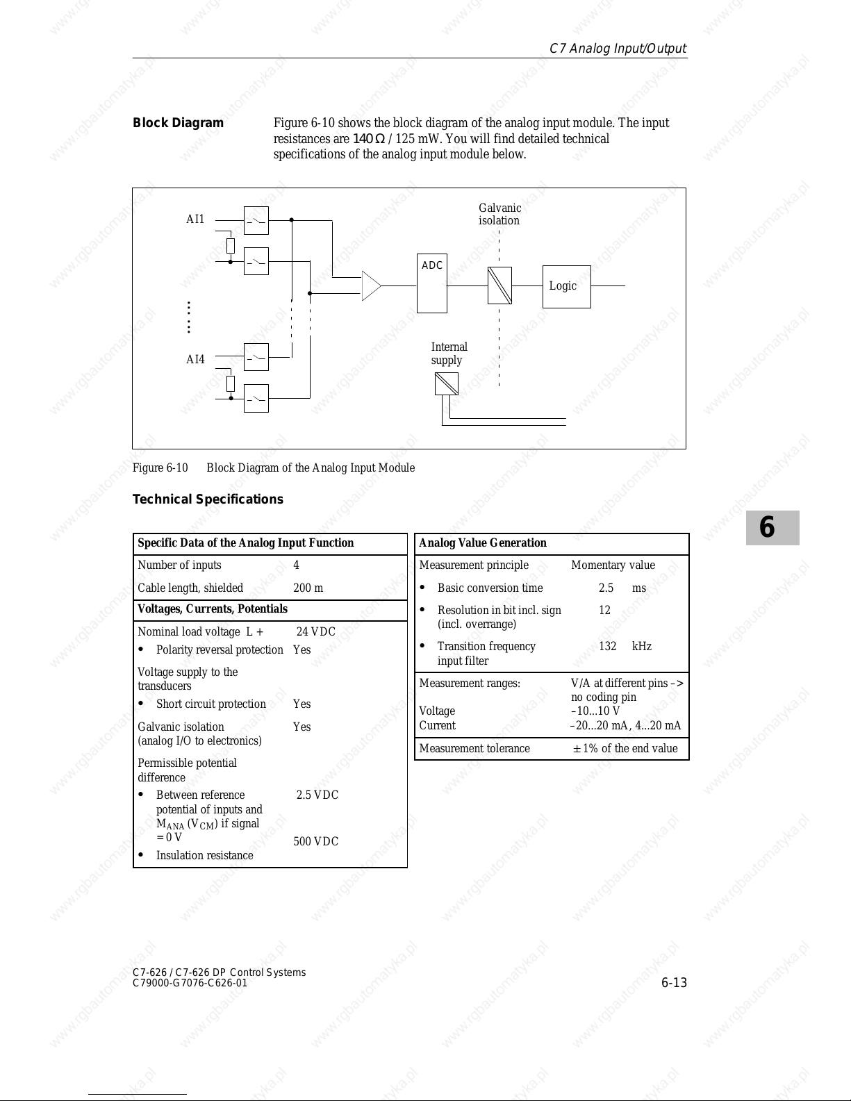
6
6-13
C7-626 / C7-626 DP Control Systems
C79000-G7076-C626-01
Figure 6-10 shows the block diagram of the analog input module. The input
resistances are 140 Ω / 125 mW. You will find detailed technical
specifications of the analog input module below.
Internal
supply
Logic
AI1
AI4
•
•
•
•
•
•
Galvanic
isolation
ADC
Figure 6-10 Block Diagram of the Analog Input Module
Technical Specifications
Specific Data of the Analog Input Function
Number of inputs 4
Cable length, shielded 200 m
Voltages, Currents, Potentials
Nominal load voltage L +
S Polarity reversal protection
24 VDC
Yes
Voltage supply to the
transducers
S Short circuit protection Yes
Galvanic isolation
(analog I/O to electronics)
Yes
Permissible potential
difference
S Between reference
potential of inputs and
M
ANA
(VCM) if signal
= 0 V
S Insulation resistance
2.5 VDC
500 VDC
Analog Value Generation
Measurement principle Momentary value
S Basic conversion time 2.5 ms
S Resolution in bit incl. sign
(incl. overrange)
12
S Transition frequency
input filter
132 kHz
Measurement ranges:
Voltage
Current
V/A at different pins –>
no coding pin
–10...10 V
–20...20 mA, 4...20 mA
Measurement tolerance 1% of the end value
Block Diagram
C7 Analog Input/Output
Page 100
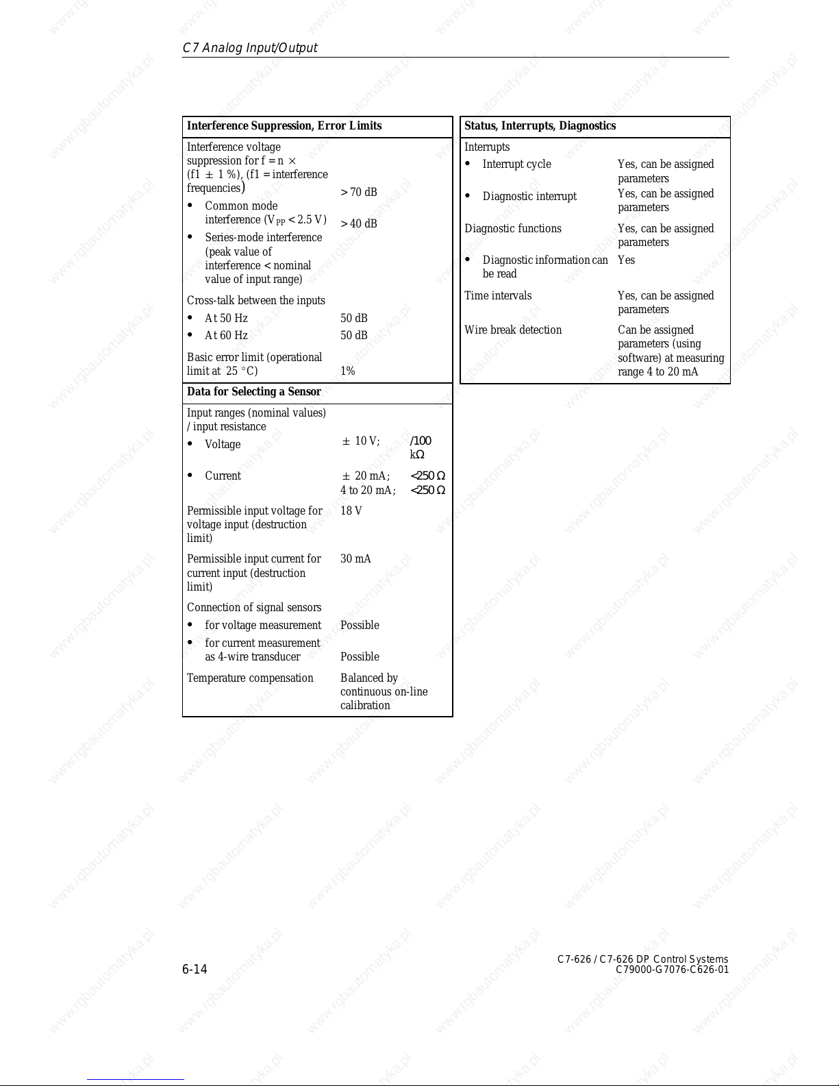
6
6-14
C7-626 / C7-626 DP Control Systems
C79000-G7076-C626-01
Interference Suppression, Error Limits
Interference voltage
suppression for f = n
(f1 " 1 %), (f1 = interference
frequencies
)
S Common mode
interference (V
PP
< 2.5 V)
S Series-mode interference
(peak value of
interference < nominal
value of input range)
> 70 dB
> 40 dB
Cross-talk between the inputs
S At 50 Hz
S At 60 Hz
50 dB
50 dB
Basic error limit (operational
limit at 25 _C)
1%
Data for Selecting a Sensor
Input ranges (nominal values)
/ input resistance
S Voltage
" 10 V; /100
kΩ
S Current " 20 mA;
4 to
20 mA;
<250 Ω
<250 Ω
Permissible input voltage for
voltage input (destruction
limit)
18 V
Permissible input current for
current input (destruction
limit)
30 mA
Connection of signal sensors
S for voltage measurement
S for current measurement
as 4-wire transducer
Possible
Possible
Temperature compensation Balanced by
continuous on-line
calibration
Status, Interrupts, Diagnostics
Interrupts
S Interrupt cycle
S Diagnostic interrupt
Yes, can be assigned
parameters
Yes, can be assigned
parameters
Diagnostic functions
S Diagnostic information can
be read
Yes, can be assigned
parameters
Yes
Time intervals Yes, can be assigned
parameters
Wire break detection Can be assigned
parameters (using
software) at measuring
range 4 to 20 mA
C7 Analog Input/Output
 Loading...